EP2246643B1 - Verfahren zum Betreiben einer Solaranlage mit Drain-Back-System - Google Patents
Verfahren zum Betreiben einer Solaranlage mit Drain-Back-System Download PDFInfo
- Publication number
- EP2246643B1 EP2246643B1 EP10004239.9A EP10004239A EP2246643B1 EP 2246643 B1 EP2246643 B1 EP 2246643B1 EP 10004239 A EP10004239 A EP 10004239A EP 2246643 B1 EP2246643 B1 EP 2246643B1
- Authority
- EP
- European Patent Office
- Prior art keywords
- solar
- shut
- valves
- operating
- absorbers
- Prior art date
- Legal status (The legal status is an assumption and is not a legal conclusion. Google has not performed a legal analysis and makes no representation as to the accuracy of the status listed.)
- Active
Links
Images
Classifications
-
- F—MECHANICAL ENGINEERING; LIGHTING; HEATING; WEAPONS; BLASTING
- F24—HEATING; RANGES; VENTILATING
- F24S—SOLAR HEAT COLLECTORS; SOLAR HEAT SYSTEMS
- F24S40/00—Safety or protection arrangements of solar heat collectors; Preventing malfunction of solar heat collectors
- F24S40/60—Arrangements for draining the working fluid
-
- F—MECHANICAL ENGINEERING; LIGHTING; HEATING; WEAPONS; BLASTING
- F24—HEATING; RANGES; VENTILATING
- F24S—SOLAR HEAT COLLECTORS; SOLAR HEAT SYSTEMS
- F24S40/00—Safety or protection arrangements of solar heat collectors; Preventing malfunction of solar heat collectors
- F24S40/70—Preventing freezing
-
- Y—GENERAL TAGGING OF NEW TECHNOLOGICAL DEVELOPMENTS; GENERAL TAGGING OF CROSS-SECTIONAL TECHNOLOGIES SPANNING OVER SEVERAL SECTIONS OF THE IPC; TECHNICAL SUBJECTS COVERED BY FORMER USPC CROSS-REFERENCE ART COLLECTIONS [XRACs] AND DIGESTS
- Y02—TECHNOLOGIES OR APPLICATIONS FOR MITIGATION OR ADAPTATION AGAINST CLIMATE CHANGE
- Y02E—REDUCTION OF GREENHOUSE GAS [GHG] EMISSIONS, RELATED TO ENERGY GENERATION, TRANSMISSION OR DISTRIBUTION
- Y02E10/00—Energy generation through renewable energy sources
- Y02E10/40—Solar thermal energy, e.g. solar towers
Definitions
- the invention relates to a method for operating a solar system with drain-back system.
- drain-back systems In solar systems with collecting containers (so-called drain-back systems, drain-back) are located in the solar circuit at a low point a relatively large container and a recirculation pump. If the circulation pump is out of operation, the fluid of the solar circuit flows by gravity into the collecting container; The solar absorber is then filled only with air and can not freeze at low temperatures or go into stagnation in the absence of heat loss. Stagnation is understood to mean the boiling of the fluid in the solar absorber.
- the drain-back system thus ensures automatic emptying of the solar absorber. Such a drain-back system avoids both the freezing and the overheating of the plant. The use of chemicals - e.g. Glycol - as frost protection is thus unnecessary.
- the pump is switched on to operate the solar absorber. The pump delivers the fluid against gravity to the collector; In this case, the pump must build up pressure and at the same time promote. If the highest point of the solar circuit is overflowed by fluid, the pump only has to provide delivery.
- US 4691692 A shows a solar system with two solar absorbers and a drainback container, in which upstream of the absorber valves are arranged.
- DE 19515580 A1 shows such a solar system, in which both upstream, and downstream shut-off valves of the absorber are arranged.
- a temperature sensor is also arranged at the absorber.
- EP 653596 A2 shows a thermal solar system with a thermal storage and a drainback container in which the deadline the connection between the memory and the solar collector is shut off, and then derive the fluid from the collector into the drainback container.
- the invention has for its object to provide a method for operating a solar system with multiple solar absorbers and a drain-back system, which is characterized by a low power consumption of the circulation pump at startup.
- shut-off valves are preferably all closed except for a shut-off valve upstream of the solar absorber, so that the circulation pump only has to promote the fluid for a solar absorber against gravity. If the first solar absorber is flooded, then only the hydraulic delivery must be applied for this. Only then will the other solar absorbers be switched on successively or simultaneously.
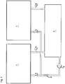
- FIG. 1 shows a solar system with several solar absorbers 1 in a circuit with a collecting container 2 (drain back) and a circulating pump 3, which is arranged in a connecting line 4 between the collecting container 2 and the solar absorbers 1.
- a circulating pump 3 Between the circulation pump 3 and the solar absorbers 1 1 shut-off valves 5 are arranged upstream of the solar absorber. Further, downstream of the solar absorber 1 at the output temperature sensors 6 or other sensors are arranged as a flow switch and shut-off valves 7.
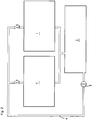
- FIG. 2 differs from FIG. 1 mainly in that the shut-off valves 5 are arranged above the solar absorber 1.
- the shut-off valves 5 of the other solar absorber 1 are closed. Then, the circulation pump 3 is put into operation, whereby against gravity, fluid is conveyed up to the solar absorbers. If the fluid has reached the highest point, this falls again due to gravity and sucks subsequent fluid while up, so that the required pump power goes back significantly. If a rapid temperature change is measured at the temperature sensor 6, which serves as a flow monitor in this case, the solar absorber 1 flows through, this is a signal that fluid has flowed through the solar absorber 1. Now, the shut-off valve 5 of the second Solar absorber 1 is opened, whereby this is flowed through. The process continues until all solar absorbers 1 are flooded.
- the shut-off valve 5 of the first solar absorber 1 is closed and the shut-off valve 5 of the next solar absorber 1 is opened. This process continues accordingly until all solar absorbers 1 have been flooded. Thereafter, all the shut-off valves 5 are opened one after the other at full pump power and the pump is regulated to nominal volume flow.
- the invention instead of the above-described temperature measurement (flow monitoring), it is also possible to wait only for a predetermined time until the next solar absorber is switched on. This time is to be determined in such a way that one can assume the full flow of a solar absorber 1. If relatively little heat is required, according to the invention only one solar absorber or a limited number of absorbers can be switched on.
- shut-off valves 5 are closed successively or jointly. Alternatively, it can also be concluded from a rapid change in the temperature of the temperature sensors 6 that no more fluid flows through the absorber; the solar absorbers must then be empty; the shut-off valves 5 can be closed, which is not mandatory. In addition, the shut-off valves 5 can be closed.
- a power-controllable solar system can be operated in which modules can be switched on or off successively depending on the power requirement or in the event of a fault.
Landscapes
- Engineering & Computer Science (AREA)
- Chemical & Material Sciences (AREA)
- Life Sciences & Earth Sciences (AREA)
- Sustainable Development (AREA)
- Sustainable Energy (AREA)
- Thermal Sciences (AREA)
- Physics & Mathematics (AREA)
- Combustion & Propulsion (AREA)
- Mechanical Engineering (AREA)
- General Engineering & Computer Science (AREA)
- Photovoltaic Devices (AREA)
- Sorption Type Refrigeration Machines (AREA)
- Electromagnetic Pumps, Or The Like (AREA)
Description
- Die Erfindung bezieht sich auf ein Verfahren zum Betreiben einer Solaranlage mit Drain-Back-System.
- Bei Solaranlagen mit Auffangbehältern (sogenannte Drain-Back-Systeme; drain-back, engl.: Rückentleerung) befinden sich im Solarkreislauf an einer niedrigen Stelle ein relativ großvolumiger Auffangbehälter und eine Umwälzpumpe. Ist die Umwälzpumpe außer Betrieb, so fließt durch die Schwerkraft das Fluid des Solarkreislaufs in den Auffangbehälter; der Solarabsorber ist dann nur mit Luft gefüllt und kann bei niedrigen Temperaturen nicht einfrieren oder bei fehlender Wärmeabnahme in Stagnation gehen. Unter Stagnation wird das Kochen des Fluids im Solarabsorber verstanden. Das Drain-Back-System sorgt somit für eine automatische Entleerung der Solarabsorber. Durch ein solches Drain-Back-System werden sowohl das Einfrieren als auch die Überhitzung der Anlage vermieden. Der Einsatz von Chemikalien - z.B. Glykol - als Frostschutz erübrigt sich somit. Zum Betrieb des Solarabsorbers wird die Pumpe eingeschaltet. Die Pumpe fördert das Fluid entgegen der Schwerkraft zum Kollektor; hierbei muss die Pumpe Druck aufbauen und zugleich fördern. Ist die höchste Stelle des Solarkreislaufs von Fluid überströmt, so muss die Pumpe nur noch Förderleistung erbringen.
-
US 4691692 A zeigt eine Solaranlage mit zwei Solarabsorbern und einem Drainbackbehälter, bei welchem stromauf der Absorber Ventile angeordnet sind. AuchDE 19515580 A1 zeigt eine derartige Solaranlage, bei welcher sowohl stromauf, als auch stromab Absperrventile der Absorber angeordnet sind. Am Absorber ist ferner ein Temperaturfühler angeordnet. -
EP 653596 A2 - Befinden sich in der Solaranlage mehrere Solarabsorber, so ist zum Start der Anlage eine sehr große Pumpenleistung erforderlich, die später im stationären Betrieb nicht mehr benötigt wird.
- Der Erfindung liegt die Aufgabe zugrunde, ein Verfahren zum Betreiben einer Solaranlage mit mehreren Solarabsorbern sowie einem Drain-Back-System zu schaffen, das sich durch einen geringen Leistungsbedarf der Umwälzpumpe beim Betriebsstart auszeichnet.
- Erfindungsgemäß wird dies gemäß den Merkmalen des unabhängigen Anspruchs 1 dadurch erreicht, dass beim Betriebsstart ein Teil der Absperrventile vorzugsweise alle bis auf ein Absperrventil stromauf der Solarabsorber geschlossen werden, so dass die Umwälzpumpe lediglich das Fluid für einen Solarabsorber entgegen der Schwerkraft fördern muss. Wird der erste Solarabsorber durchflutet, so muss für diesen nur noch die hydraulische Förderleistung aufgebracht werden. Erst dann werden die anderen Solarabsorber sukzessiv oder gleichzeitig zugeschaltet.
- Die Erfindung wird nun anhand der Figuren detailliert erläutert, wobei gleiche Bezugszeichen sich auf gleiche Bauteile beziehen. Hierbei zeigen:
- Figur 1
- eine Solaranlage für den erfindungsgemäßen Betrieb und
- Figur 2
- eine alternative Solaranlage hierfür.
-
Figur 1 zeigt eine Solaranlage mit mehreren Solarabsorbern 1 in einem Kreislauf mit einem Auffangbehälter 2 (Drain-Back) und einer Umwälzpumpe 3, welche in einer Verbindungsleitung 4 zwischen dem Auffangbehälter 2 und den Solarabsorbern 1 angeordnet ist. Zwischen der Umwälzpumpe 3 und den Solarabsorbern 1 sind stromauf der Solarabsorber 1 Absperrventile 5 angeordnet. Ferner sind stromab der Solarabsorber 1 am Ausgang Temperatursensoren 6 oder andere Sensoren als Strömungswächter und Absperrventile 7 angeordnet. -
Figur 2 unterscheidet sich vonFigur 1 hauptsächlich dadurch, dass die Absperrventile 5 oberhalb der Solarabsorber 1 angeordnet sind. - Zum Starten der Solaranlage werden bis auf das Absperrventil 5 eines einzigen Solarabsorbers 1 die Absperrventile 5 der anderen Solarabsorber 1 geschlossen. Dann wird die Umwälzpumpe 3 in Betrieb genommen, wodurch entgegen der Schwerkraft Fluid nach oben zu den Solarabsorbern gefördert wird. Hat das Fluid den höchsten Punkt erreicht, so fällt dieses aufgrund der Schwerkraft wieder und saugt nachfolgendes Fluid dabei nach oben, so dass die benötigte Pumpenleistung deutlich zurück geht. Wird an dem Temperatursensor 6, der in diesem Fall als Strömungswächter dient, des durchströmten Solarabsorbers 1 eine rasche Temperaturänderung gemessen, so ist dies ein Signal dafür, dass Fluid den Solarabsorber 1 durchströmt hat. Nun wird das Absperrventil 5 des zweiten Solarabsorbers 1 geöffnet, wodurch auch dieser durchströmt wird. Der Vorgang wird fortgesetzt, bis alle Solarabsorber 1 durchflutet sind.
- Alternativ kann, nachdem der Temperatursensor 6 des ersten Solarabsorbers 1 eine rasche Temperaturänderung gemessen, das Absperrventil 5 des ersten Solarabsorbers 1 geschlossen werden und das Absperrventil 5 des nächsten Solarabsorbers 1 geöffnet werden. Dieser Vorgang wird entsprechend fortgesetzt, bis alle Solarabsorber 1 durchflutet wurden. Danach werden bei voller Pumpenleistung alle Absperrventile 5 nacheinander geöffnet und die Pumpe auf Nennvolumenstrom geregelt.
- Erfindungsgemäß kann anstelle der oben geschilderten Temperaturmessung (Strömungsüberwachung) auch einfach nur eine vorbestimmte Zeit bis zum Zuschalten des nächsten Solarabsorbers gewartet werden. Diese Zeit ist derart zu bestimmen, dass man vom vollständigen Durchfluten eines Solarabsorbers 1 ausgehen kann. Wird relativ wenig Wärme benötigt, so kann erfindungsgemäß auch nur ein Solarabsorber oder eine begrenzte Anzahl Absorber zugeschaltet werden.
- Zum Abschalten der Solaranlage wird erst die Umwälzpumpe 3 abgeschaltet. Nach Ablauf einer vorbestimmten Zeit werden die Absperrventile 5 sukzessiv oder gemeinsam geschlossen. Alternativ kann auch aus einer raschen Veränderung der Temperatur der Temperatursensoren 6 darauf geschlossen werden, dass kein Fluid mehr durch die Absorber strömt; die Solarabsorber müssen dann leer sein; die Absperrventile 5 können geschlossen werden, was jedoch nicht zwingend ist. Zusätzlich können die Absperrventile 5 geschlossen werden.
- Weiterhin besteht die Möglichkeit aufgrund rascher Temperaturveränderungen nur einzelne Kollektoren durch Schließen der Absperrventile 5 und Öffnen eines (nicht dargestellte) Bypasses während des Betriebs außer Betrieb zu nehmen.
- Hierdruch ist eine leistungsregelbare Solaranlage betreibbar, bei der sukzessiv je nach Leistungsbedarf oder im Störungsfall Module zu- oder abgeschaltet werden können.
Claims (4)
- Verfahren zum Betreiben einer Solaranlage mit mehreren Solarabsorbern (1) sowie mindestens einem Auffangbehälter (2) (Drain-Back) und einer Umwälzpumpe (3), welche in einer Verbindungsleitung (4) zwischen dem mindestens einen Auffangbehälter (2) und den Solarabsorbern (1) angeordnet ist, wobei stromauf der Solarabsorber (1) Absperrventile (5) angeordnet sind, dadurch gekennzeichnet, dass zum Starten der Solaranlage ein Teil der Absperrventile (5) stromauf der Solarabsorber (1), vorzugsweise alle bis auf ein einzelnes Absperrventil (5), geschlossen werden, die Umwälzpumpe (3) in Betrieb genommen wird und erst nach Ablauf einer vorbestimmten Zeit oder beim Eintritt eines vorbestimmten Ereignisses die anderen Absperrventile (5) sukzessiv oder gemeinsam zugeschaltet werden.
- Verfahren zum Betreiben einer Solaranlage nach Anspruch 1, dadurch gekennzeichnet, dass das vorbestimmte Ereignis das vollständige Durchströmen eines Solarkollektors (1), was anhand eines großen Temperaturgradienten am Temperatursensor (6) am Ausgang des Solarkollektors (1) erkannt wird, ist.
- Verfahren zum Betreiben einer Solaranlage nach Anspruch 1 oder 2, dadurch gekennzeichnet, dass beim Abschalten erst die Umwälzpumpe (3) abgeschaltet wird und erst nach Ablauf einer vorbestimmten Zeit oder beim Eintritt eines vorbestimmten Ereignisses die Absperrventile (5) sukzessiv oder gemeinsam geschlossen werden.
- Verfahren zum Betreiben einer Solaranlage nach einem der Ansprüche 1 bis 3 mit einem Temperatursensor (6) stromab der Solarabsorber (1), dadurch gekennzeichnet, dass das vorbestimmte Ereignis das vollständige Entleeren eines Solarkollektors (1), was anhand eines großen Temperaturgradienten am Temperatursensor (6) oder einem sonstigen äquivalenten Signal eines anderen Strömungswächter am Ausgang eines Solarkollektors (1) oder einer Kollektoreneinheit erkannt wird, ist.
Applications Claiming Priority (1)
| Application Number | Priority Date | Filing Date | Title |
|---|---|---|---|
| DE102009019246 | 2009-04-30 |
Publications (3)
| Publication Number | Publication Date |
|---|---|
| EP2246643A2 EP2246643A2 (de) | 2010-11-03 |
| EP2246643A3 EP2246643A3 (de) | 2016-09-21 |
| EP2246643B1 true EP2246643B1 (de) | 2019-06-05 |
Family
ID=42579643
Family Applications (1)
| Application Number | Title | Priority Date | Filing Date |
|---|---|---|---|
| EP10004239.9A Active EP2246643B1 (de) | 2009-04-30 | 2010-04-21 | Verfahren zum Betreiben einer Solaranlage mit Drain-Back-System |
Country Status (1)
| Country | Link |
|---|---|
| EP (1) | EP2246643B1 (de) |
Families Citing this family (1)
| Publication number | Priority date | Publication date | Assignee | Title |
|---|---|---|---|---|
| CN106679200B (zh) * | 2015-11-10 | 2020-07-28 | 陈宇奇 | 一种太阳能集热器集热管热力切换系统 |
Family Cites Families (5)
| Publication number | Priority date | Publication date | Assignee | Title |
|---|---|---|---|---|
| US4691692A (en) * | 1985-12-05 | 1987-09-08 | Conner Jr Leo B | Solar energy system with delayed drain-back |
| DE4338604A1 (de) * | 1993-11-11 | 1995-05-18 | Sandler Energietechnik | Solarkollektor-Befüllung & Entleerung |
| DE19515580A1 (de) * | 1994-04-28 | 1995-11-02 | Hans Ing Thurner | Anlage zur Gewinnung von Sonnenenergie |
| DE19654037C1 (de) * | 1996-12-23 | 1998-07-02 | Solar Diamant Systemtechnik Gm | Anlage zur Gewinnung von Wärme aus Solarenergie |
| PL356349A1 (en) * | 2002-09-27 | 2004-04-05 | Adam Skorut | Method of safe transfer of solar energy and low-pressure system for transmission of solar energy |
-
2010
- 2010-04-21 EP EP10004239.9A patent/EP2246643B1/de active Active
Non-Patent Citations (1)
| Title |
|---|
| None * |
Also Published As
| Publication number | Publication date |
|---|---|
| EP2246643A2 (de) | 2010-11-03 |
| EP2246643A3 (de) | 2016-09-21 |
Similar Documents
| Publication | Publication Date | Title |
|---|---|---|
| DE102012004094B3 (de) | Vorrichtung, insbesondere Wärmepumpe, mit einem in einem Kreislauf geführten Kältemittel sowie Verfahren zum Betrieb einer derartigen Vorrichtung | |
| EP2806168B1 (de) | Umwälzpumpenaggregat und solarthermische Anlage damit | |
| EP2009359B1 (de) | Verfahren zum Betrieb einer solarthermischen Anlage | |
| DE102019006054A1 (de) | Solaranlage und ein Verfahren zum Betrieb der Solaranlage | |
| EP2524634A1 (de) | Getränkeautomat | |
| DE102008029654A1 (de) | Anordnung und Verfahren zur Bereitstellung von warmem Trinkwasser mit einem Wärmeübertrager | |
| DE102019200324A1 (de) | Vorrichtung und Verfahren zur Wärmerückgewinnung aus einem flüssigen Medium | |
| DE19654037C1 (de) | Anlage zur Gewinnung von Wärme aus Solarenergie | |
| EP1320663A1 (de) | Verfahren und vorrichtung zum warmziehen und entwässern von an dampfturbinen angeschlossene dampfzuleitungen | |
| EP2246643B1 (de) | Verfahren zum Betreiben einer Solaranlage mit Drain-Back-System | |
| DE102005035821B3 (de) | Thermische Solaranlage | |
| WO2012143226A2 (de) | Latentwärmespeichereinrichtung und betriebsverfahren für eine latentwärmespeichereinrichtung | |
| DE102009006722B4 (de) | Solarheizanlage, Verfahren und Vorrichtung zur Diagnose einer Luftmenge in einem mit einem Solarfluid befüllten Solarfluidkreis und zum Betreiben einer Solarheizanlage | |
| EP2213951B1 (de) | Solarheizanlage, Verfahren und Vorrichtung zur Verlängerung der Laufzeit einer Anlage mit einem geschlossenen Fluidkreislauf | |
| DE102008060973A1 (de) | Entlüftungsventil für solarthermische Anlagen und dazugehöriges Verfahren | |
| DE10341741C5 (de) | Solaranlage | |
| EP3914872B1 (de) | Wärmetauschermodul, wärmetauschersystem und verfahren zum herstellen des wärmetauschersystems | |
| DE102006054046B3 (de) | Heizungs-Wärmepumpen-Anlage mit zwei Wärmetauschern | |
| WO2012025389A9 (de) | Ausdehnungssystem des wärmeträgermedium-kreislaufes eines solarthermischen kraftwerks | |
| EP3179178A1 (de) | Solaranlage im drain-back verfahren und ein verfahren zu deren betriebnahme | |
| EP2208939B1 (de) | Solarthermische Anlage | |
| EP2405205B1 (de) | Gasabscheider in einer Solaranlage zur Wärmegewinnung | |
| DE102011119954B4 (de) | Vorrichtung zur Enteisung einer Photovoltaik- oder Solaranlage | |
| DE202009014744U1 (de) | Thermische Solaranlage | |
| EP2320148A2 (de) | Solarthermische Anlage mit wenigstens einem Kollektor für Sonnenwärme |
Legal Events
| Date | Code | Title | Description |
|---|---|---|---|
| PUAI | Public reference made under article 153(3) epc to a published international application that has entered the european phase |
Free format text: ORIGINAL CODE: 0009012 |
|
| AK | Designated contracting states |
Kind code of ref document: A2 Designated state(s): AT BE BG CH CY CZ DE DK EE ES FI FR GB GR HR HU IE IS IT LI LT LU LV MC MK MT NL NO PL PT RO SE SI SK SM TR |
|
| AX | Request for extension of the european patent |
Extension state: AL BA ME RS |
|
| PUAL | Search report despatched |
Free format text: ORIGINAL CODE: 0009013 |
|
| AK | Designated contracting states |
Kind code of ref document: A3 Designated state(s): AT BE BG CH CY CZ DE DK EE ES FI FR GB GR HR HU IE IS IT LI LT LU LV MC MK MT NL NO PL PT RO SE SI SK SM TR |
|
| AX | Request for extension of the european patent |
Extension state: AL BA ME RS |
|
| RIC1 | Information provided on ipc code assigned before grant |
Ipc: F24J 2/46 20060101AFI20160816BHEP |
|
| STAA | Information on the status of an ep patent application or granted ep patent |
Free format text: STATUS: REQUEST FOR EXAMINATION WAS MADE |
|
| 17P | Request for examination filed |
Effective date: 20170222 |
|
| RBV | Designated contracting states (corrected) |
Designated state(s): AT BE BG CH CY CZ DE DK EE ES FI FR GB GR HR HU IE IS IT LI LT LU LV MC MK MT NL NO PL PT RO SE SI SK SM TR |
|
| REG | Reference to a national code |
Ref country code: DE Ref legal event code: R079 Ref document number: 502010016029 Country of ref document: DE Free format text: PREVIOUS MAIN CLASS: F24J0002460000 Ipc: F24S0040700000 |
|
| GRAP | Despatch of communication of intention to grant a patent |
Free format text: ORIGINAL CODE: EPIDOSNIGR1 |
|
| STAA | Information on the status of an ep patent application or granted ep patent |
Free format text: STATUS: GRANT OF PATENT IS INTENDED |
|
| RIC1 | Information provided on ipc code assigned before grant |
Ipc: F24S 40/70 20180101AFI20181210BHEP |
|
| INTG | Intention to grant announced |
Effective date: 20190103 |
|
| RIC1 | Information provided on ipc code assigned before grant |
Ipc: F24S 40/70 20180101AFI20181210BHEP |
|
| GRAS | Grant fee paid |
Free format text: ORIGINAL CODE: EPIDOSNIGR3 |
|
| GRAA | (expected) grant |
Free format text: ORIGINAL CODE: 0009210 |
|
| STAA | Information on the status of an ep patent application or granted ep patent |
Free format text: STATUS: THE PATENT HAS BEEN GRANTED |
|
| AK | Designated contracting states |
Kind code of ref document: B1 Designated state(s): AT BE BG CH CY CZ DE DK EE ES FI FR GB GR HR HU IE IS IT LI LT LU LV MC MK MT NL NO PL PT RO SE SI SK SM TR |
|
| REG | Reference to a national code |
Ref country code: GB Ref legal event code: FG4D Free format text: NOT ENGLISH |
|
| REG | Reference to a national code |
Ref country code: CH Ref legal event code: EP |
|
| REG | Reference to a national code |
Ref country code: AT Ref legal event code: REF Ref document number: 1140424 Country of ref document: AT Kind code of ref document: T Effective date: 20190615 |
|
| REG | Reference to a national code |
Ref country code: IE Ref legal event code: FG4D Free format text: LANGUAGE OF EP DOCUMENT: GERMAN |
|
| REG | Reference to a national code |
Ref country code: DE Ref legal event code: R096 Ref document number: 502010016029 Country of ref document: DE |
|
| REG | Reference to a national code |
Ref country code: NL Ref legal event code: MP Effective date: 20190605 |
|
| REG | Reference to a national code |
Ref country code: LT Ref legal event code: MG4D |
|
| PG25 | Lapsed in a contracting state [announced via postgrant information from national office to epo] |
Ref country code: FI Free format text: LAPSE BECAUSE OF FAILURE TO SUBMIT A TRANSLATION OF THE DESCRIPTION OR TO PAY THE FEE WITHIN THE PRESCRIBED TIME-LIMIT Effective date: 20190605 Ref country code: LT Free format text: LAPSE BECAUSE OF FAILURE TO SUBMIT A TRANSLATION OF THE DESCRIPTION OR TO PAY THE FEE WITHIN THE PRESCRIBED TIME-LIMIT Effective date: 20190605 Ref country code: ES Free format text: LAPSE BECAUSE OF FAILURE TO SUBMIT A TRANSLATION OF THE DESCRIPTION OR TO PAY THE FEE WITHIN THE PRESCRIBED TIME-LIMIT Effective date: 20190605 Ref country code: SE Free format text: LAPSE BECAUSE OF FAILURE TO SUBMIT A TRANSLATION OF THE DESCRIPTION OR TO PAY THE FEE WITHIN THE PRESCRIBED TIME-LIMIT Effective date: 20190605 Ref country code: HR Free format text: LAPSE BECAUSE OF FAILURE TO SUBMIT A TRANSLATION OF THE DESCRIPTION OR TO PAY THE FEE WITHIN THE PRESCRIBED TIME-LIMIT Effective date: 20190605 Ref country code: NO Free format text: LAPSE BECAUSE OF FAILURE TO SUBMIT A TRANSLATION OF THE DESCRIPTION OR TO PAY THE FEE WITHIN THE PRESCRIBED TIME-LIMIT Effective date: 20190905 |
|
| PG25 | Lapsed in a contracting state [announced via postgrant information from national office to epo] |
Ref country code: GR Free format text: LAPSE BECAUSE OF FAILURE TO SUBMIT A TRANSLATION OF THE DESCRIPTION OR TO PAY THE FEE WITHIN THE PRESCRIBED TIME-LIMIT Effective date: 20190906 Ref country code: LV Free format text: LAPSE BECAUSE OF FAILURE TO SUBMIT A TRANSLATION OF THE DESCRIPTION OR TO PAY THE FEE WITHIN THE PRESCRIBED TIME-LIMIT Effective date: 20190605 Ref country code: BG Free format text: LAPSE BECAUSE OF FAILURE TO SUBMIT A TRANSLATION OF THE DESCRIPTION OR TO PAY THE FEE WITHIN THE PRESCRIBED TIME-LIMIT Effective date: 20190905 |
|
| PG25 | Lapsed in a contracting state [announced via postgrant information from national office to epo] |
Ref country code: SK Free format text: LAPSE BECAUSE OF FAILURE TO SUBMIT A TRANSLATION OF THE DESCRIPTION OR TO PAY THE FEE WITHIN THE PRESCRIBED TIME-LIMIT Effective date: 20190605 Ref country code: EE Free format text: LAPSE BECAUSE OF FAILURE TO SUBMIT A TRANSLATION OF THE DESCRIPTION OR TO PAY THE FEE WITHIN THE PRESCRIBED TIME-LIMIT Effective date: 20190605 Ref country code: CZ Free format text: LAPSE BECAUSE OF FAILURE TO SUBMIT A TRANSLATION OF THE DESCRIPTION OR TO PAY THE FEE WITHIN THE PRESCRIBED TIME-LIMIT Effective date: 20190605 Ref country code: NL Free format text: LAPSE BECAUSE OF FAILURE TO SUBMIT A TRANSLATION OF THE DESCRIPTION OR TO PAY THE FEE WITHIN THE PRESCRIBED TIME-LIMIT Effective date: 20190605 Ref country code: RO Free format text: LAPSE BECAUSE OF FAILURE TO SUBMIT A TRANSLATION OF THE DESCRIPTION OR TO PAY THE FEE WITHIN THE PRESCRIBED TIME-LIMIT Effective date: 20190605 Ref country code: PT Free format text: LAPSE BECAUSE OF FAILURE TO SUBMIT A TRANSLATION OF THE DESCRIPTION OR TO PAY THE FEE WITHIN THE PRESCRIBED TIME-LIMIT Effective date: 20191007 |
|
| PG25 | Lapsed in a contracting state [announced via postgrant information from national office to epo] |
Ref country code: SM Free format text: LAPSE BECAUSE OF FAILURE TO SUBMIT A TRANSLATION OF THE DESCRIPTION OR TO PAY THE FEE WITHIN THE PRESCRIBED TIME-LIMIT Effective date: 20190605 Ref country code: IS Free format text: LAPSE BECAUSE OF FAILURE TO SUBMIT A TRANSLATION OF THE DESCRIPTION OR TO PAY THE FEE WITHIN THE PRESCRIBED TIME-LIMIT Effective date: 20191005 Ref country code: IT Free format text: LAPSE BECAUSE OF FAILURE TO SUBMIT A TRANSLATION OF THE DESCRIPTION OR TO PAY THE FEE WITHIN THE PRESCRIBED TIME-LIMIT Effective date: 20190605 |
|
| REG | Reference to a national code |
Ref country code: DE Ref legal event code: R097 Ref document number: 502010016029 Country of ref document: DE |
|
| PG25 | Lapsed in a contracting state [announced via postgrant information from national office to epo] |
Ref country code: TR Free format text: LAPSE BECAUSE OF FAILURE TO SUBMIT A TRANSLATION OF THE DESCRIPTION OR TO PAY THE FEE WITHIN THE PRESCRIBED TIME-LIMIT Effective date: 20190605 |
|
| PLBE | No opposition filed within time limit |
Free format text: ORIGINAL CODE: 0009261 |
|
| STAA | Information on the status of an ep patent application or granted ep patent |
Free format text: STATUS: NO OPPOSITION FILED WITHIN TIME LIMIT |
|
| PG25 | Lapsed in a contracting state [announced via postgrant information from national office to epo] |
Ref country code: PL Free format text: LAPSE BECAUSE OF FAILURE TO SUBMIT A TRANSLATION OF THE DESCRIPTION OR TO PAY THE FEE WITHIN THE PRESCRIBED TIME-LIMIT Effective date: 20190605 Ref country code: DK Free format text: LAPSE BECAUSE OF FAILURE TO SUBMIT A TRANSLATION OF THE DESCRIPTION OR TO PAY THE FEE WITHIN THE PRESCRIBED TIME-LIMIT Effective date: 20190605 |
|
| 26N | No opposition filed |
Effective date: 20200306 |
|
| PG25 | Lapsed in a contracting state [announced via postgrant information from national office to epo] |
Ref country code: SI Free format text: LAPSE BECAUSE OF FAILURE TO SUBMIT A TRANSLATION OF THE DESCRIPTION OR TO PAY THE FEE WITHIN THE PRESCRIBED TIME-LIMIT Effective date: 20190605 |
|
| REG | Reference to a national code |
Ref country code: DE Ref legal event code: R119 Ref document number: 502010016029 Country of ref document: DE |
|
| PG25 | Lapsed in a contracting state [announced via postgrant information from national office to epo] |
Ref country code: MC Free format text: LAPSE BECAUSE OF FAILURE TO SUBMIT A TRANSLATION OF THE DESCRIPTION OR TO PAY THE FEE WITHIN THE PRESCRIBED TIME-LIMIT Effective date: 20190605 |
|
| REG | Reference to a national code |
Ref country code: CH Ref legal event code: PL |
|
| PG25 | Lapsed in a contracting state [announced via postgrant information from national office to epo] |
Ref country code: DE Free format text: LAPSE BECAUSE OF NON-PAYMENT OF DUE FEES Effective date: 20201103 Ref country code: LU Free format text: LAPSE BECAUSE OF NON-PAYMENT OF DUE FEES Effective date: 20200421 Ref country code: CH Free format text: LAPSE BECAUSE OF NON-PAYMENT OF DUE FEES Effective date: 20200430 Ref country code: LI Free format text: LAPSE BECAUSE OF NON-PAYMENT OF DUE FEES Effective date: 20200430 Ref country code: FR Free format text: LAPSE BECAUSE OF NON-PAYMENT OF DUE FEES Effective date: 20200430 |
|
| REG | Reference to a national code |
Ref country code: BE Ref legal event code: MM Effective date: 20200430 |
|
| PG25 | Lapsed in a contracting state [announced via postgrant information from national office to epo] |
Ref country code: BE Free format text: LAPSE BECAUSE OF NON-PAYMENT OF DUE FEES Effective date: 20200430 |
|
| GBPC | Gb: european patent ceased through non-payment of renewal fee |
Effective date: 20200421 |
|
| PG25 | Lapsed in a contracting state [announced via postgrant information from national office to epo] |
Ref country code: GB Free format text: LAPSE BECAUSE OF NON-PAYMENT OF DUE FEES Effective date: 20200421 Ref country code: IE Free format text: LAPSE BECAUSE OF NON-PAYMENT OF DUE FEES Effective date: 20200421 |
|
| REG | Reference to a national code |
Ref country code: AT Ref legal event code: MM01 Ref document number: 1140424 Country of ref document: AT Kind code of ref document: T Effective date: 20200421 |
|
| PG25 | Lapsed in a contracting state [announced via postgrant information from national office to epo] |
Ref country code: AT Free format text: LAPSE BECAUSE OF NON-PAYMENT OF DUE FEES Effective date: 20200421 |
|
| PG25 | Lapsed in a contracting state [announced via postgrant information from national office to epo] |
Ref country code: MT Free format text: LAPSE BECAUSE OF FAILURE TO SUBMIT A TRANSLATION OF THE DESCRIPTION OR TO PAY THE FEE WITHIN THE PRESCRIBED TIME-LIMIT Effective date: 20190605 Ref country code: CY Free format text: LAPSE BECAUSE OF FAILURE TO SUBMIT A TRANSLATION OF THE DESCRIPTION OR TO PAY THE FEE WITHIN THE PRESCRIBED TIME-LIMIT Effective date: 20190605 |
|
| PG25 | Lapsed in a contracting state [announced via postgrant information from national office to epo] |
Ref country code: MK Free format text: LAPSE BECAUSE OF FAILURE TO SUBMIT A TRANSLATION OF THE DESCRIPTION OR TO PAY THE FEE WITHIN THE PRESCRIBED TIME-LIMIT Effective date: 20190605 |