EP2246293B1 - Integriertes Verfahren zum Generieren von Energie und/oder Synthesegas durch Herstellung von Sauerstoff in situ, Verbrennung und Vergasung in einem chemischen Kreisprozess - Google Patents
Integriertes Verfahren zum Generieren von Energie und/oder Synthesegas durch Herstellung von Sauerstoff in situ, Verbrennung und Vergasung in einem chemischen Kreisprozess Download PDFInfo
- Publication number
- EP2246293B1 EP2246293B1 EP10290157A EP10290157A EP2246293B1 EP 2246293 B1 EP2246293 B1 EP 2246293B1 EP 10290157 A EP10290157 A EP 10290157A EP 10290157 A EP10290157 A EP 10290157A EP 2246293 B1 EP2246293 B1 EP 2246293B1
- Authority
- EP
- European Patent Office
- Prior art keywords
- oxygen
- zone
- reduction
- gasification
- oxidation
- Prior art date
- Legal status (The legal status is an assumption and is not a legal conclusion. Google has not performed a legal analysis and makes no representation as to the accuracy of the status listed.)
- Not-in-force
Links
Images
Classifications
-
- C—CHEMISTRY; METALLURGY
- C01—INORGANIC CHEMISTRY
- C01B—NON-METALLIC ELEMENTS; COMPOUNDS THEREOF; METALLOIDS OR COMPOUNDS THEREOF NOT COVERED BY SUBCLASS C01C
- C01B13/00—Oxygen; Ozone; Oxides or hydroxides in general
- C01B13/02—Preparation of oxygen
- C01B13/0203—Preparation of oxygen from inorganic compounds
-
- C—CHEMISTRY; METALLURGY
- C01—INORGANIC CHEMISTRY
- C01B—NON-METALLIC ELEMENTS; COMPOUNDS THEREOF; METALLOIDS OR COMPOUNDS THEREOF NOT COVERED BY SUBCLASS C01C
- C01B3/00—Hydrogen; Gaseous mixtures containing hydrogen; Separation of hydrogen from mixtures containing it; Purification of hydrogen; Reversible storage of hydrogen
- C01B3/02—Production of hydrogen; Production of gaseous mixtures containing hydrogen
- C01B3/32—Production of hydrogen; Production of gaseous mixtures containing hydrogen by reaction of gaseous or liquid organic compounds with gasifying agents, e.g. water, carbon dioxide or air
- C01B3/34—Production of hydrogen; Production of gaseous mixtures containing hydrogen by reaction of gaseous or liquid organic compounds with gasifying agents, e.g. water, carbon dioxide or air by reaction of hydrocarbons with gasifying agents
- C01B3/36—Production of hydrogen; Production of gaseous mixtures containing hydrogen by reaction of gaseous or liquid organic compounds with gasifying agents, e.g. water, carbon dioxide or air by reaction of hydrocarbons with gasifying agents using oxygen; using mixtures containing oxygen as gasifying agents
-
- C—CHEMISTRY; METALLURGY
- C01—INORGANIC CHEMISTRY
- C01B—NON-METALLIC ELEMENTS; COMPOUNDS THEREOF; METALLOIDS OR COMPOUNDS THEREOF NOT COVERED BY SUBCLASS C01C
- C01B3/00—Hydrogen; Gaseous mixtures containing hydrogen; Separation of hydrogen from mixtures containing it; Purification of hydrogen; Reversible storage of hydrogen
- C01B3/02—Production of hydrogen; Production of gaseous mixtures containing hydrogen
- C01B3/32—Production of hydrogen; Production of gaseous mixtures containing hydrogen by reaction of gaseous or liquid organic compounds with gasifying agents, e.g. water, carbon dioxide or air
- C01B3/34—Production of hydrogen; Production of gaseous mixtures containing hydrogen by reaction of gaseous or liquid organic compounds with gasifying agents, e.g. water, carbon dioxide or air by reaction of hydrocarbons with gasifying agents
- C01B3/46—Production of hydrogen; Production of gaseous mixtures containing hydrogen by reaction of gaseous or liquid organic compounds with gasifying agents, e.g. water, carbon dioxide or air by reaction of hydrocarbons with gasifying agents using discontinuously preheated non-moving solid materials, e.g. blast and run
-
- C—CHEMISTRY; METALLURGY
- C10—PETROLEUM, GAS OR COKE INDUSTRIES; TECHNICAL GASES CONTAINING CARBON MONOXIDE; FUELS; LUBRICANTS; PEAT
- C10J—PRODUCTION OF PRODUCER GAS, WATER-GAS, SYNTHESIS GAS FROM SOLID CARBONACEOUS MATERIAL, OR MIXTURES CONTAINING THESE GASES; CARBURETTING AIR OR OTHER GASES
- C10J3/00—Production of combustible gases containing carbon monoxide from solid carbonaceous fuels
- C10J3/72—Other features
- C10J3/725—Redox processes
-
- C—CHEMISTRY; METALLURGY
- C01—INORGANIC CHEMISTRY
- C01B—NON-METALLIC ELEMENTS; COMPOUNDS THEREOF; METALLOIDS OR COMPOUNDS THEREOF NOT COVERED BY SUBCLASS C01C
- C01B2203/00—Integrated processes for the production of hydrogen or synthesis gas
- C01B2203/02—Processes for making hydrogen or synthesis gas
- C01B2203/025—Processes for making hydrogen or synthesis gas containing a partial oxidation step
- C01B2203/0255—Processes for making hydrogen or synthesis gas containing a partial oxidation step containing a non-catalytic partial oxidation step
-
- C—CHEMISTRY; METALLURGY
- C10—PETROLEUM, GAS OR COKE INDUSTRIES; TECHNICAL GASES CONTAINING CARBON MONOXIDE; FUELS; LUBRICANTS; PEAT
- C10J—PRODUCTION OF PRODUCER GAS, WATER-GAS, SYNTHESIS GAS FROM SOLID CARBONACEOUS MATERIAL, OR MIXTURES CONTAINING THESE GASES; CARBURETTING AIR OR OTHER GASES
- C10J2300/00—Details of gasification processes
- C10J2300/09—Details of the feed, e.g. feeding of spent catalyst, inert gas or halogens
- C10J2300/0953—Gasifying agents
- C10J2300/0959—Oxygen
-
- C—CHEMISTRY; METALLURGY
- C10—PETROLEUM, GAS OR COKE INDUSTRIES; TECHNICAL GASES CONTAINING CARBON MONOXIDE; FUELS; LUBRICANTS; PEAT
- C10J—PRODUCTION OF PRODUCER GAS, WATER-GAS, SYNTHESIS GAS FROM SOLID CARBONACEOUS MATERIAL, OR MIXTURES CONTAINING THESE GASES; CARBURETTING AIR OR OTHER GASES
- C10J2300/00—Details of gasification processes
- C10J2300/18—Details of the gasification process, e.g. loops, autothermal operation
- C10J2300/1807—Recycle loops, e.g. gas, solids, heating medium, water
-
- Y—GENERAL TAGGING OF NEW TECHNOLOGICAL DEVELOPMENTS; GENERAL TAGGING OF CROSS-SECTIONAL TECHNOLOGIES SPANNING OVER SEVERAL SECTIONS OF THE IPC; TECHNICAL SUBJECTS COVERED BY FORMER USPC CROSS-REFERENCE ART COLLECTIONS [XRACs] AND DIGESTS
- Y02—TECHNOLOGIES OR APPLICATIONS FOR MITIGATION OR ADAPTATION AGAINST CLIMATE CHANGE
- Y02P—CLIMATE CHANGE MITIGATION TECHNOLOGIES IN THE PRODUCTION OR PROCESSING OF GOODS
- Y02P20/00—Technologies relating to chemical industry
- Y02P20/10—Process efficiency
Definitions
- the oxyfuel combustion units have the advantage of producing combustion fumes that are free of nitrogen from the combustion air since the combustion is made from pure oxygen.
- This oxygen is produced by an air separation unit (ASU).
- a disadvantage of this mode of combustion and ASUs in particular is their high energy consumption and their high investment cost which greatly increases the overall cost of capture.
- Chemical loop combustion has significant potential for energy efficiency and cost reduction. This process avoids the energy penalty related to the separation of oxygen from the air. It is based on the oxygen transfer capacity of certain materials such as metal oxides.
- An air reactor is used to oxidize the oxygen carriers prepared as fine particles which are then transferred to a fuel reactor where they are reduced by the combustion of the fuel. This process is generally carried out on a pilot scale in the form of two fluidized beds exchanging solids streams: the air reactor then being a fast fluidization type reactor at the top of which the flow of oxygen depleted air and the particles are separated.
- the document W02007082089A2 consists of a three-step process that highlights the use of metal oxide recirculation for hydrogen production.
- a first reactor a total combustion of the fuel makes it possible to produce CO2, H2O.
- the production of hydrogen is carried out by reoxidation of the metal oxide with steam.
- This embodiment imposes significant steam flows and therefore the need to heat and evaporate a large amount of water before introduction into the oxidation reactor, resulting in a limiting energy balance.
- Hydrogen production can also be carried out by gasification: the patent application WO2008036902A2 describes for example a hydrocarbon gasification process which is carried out in a conventional arrangement of two reaction zones.
- Some oxygen carriers have the ability to spontaneously release some of their oxygen in a low oxygen environment.
- an oxygen production reactor within a chemical loop makes it possible to gasify the fuel with a mixture enriched with oxygen avoiding direct contact solid - solid fuel. This avoids the need for solid-solid separation equipment.
- This particular configuration also has the advantage of improving the energy balance of the gasification step, which is very endothermic in the absence of oxygen, but also of accelerating the reactions since the reactions involved are reactions between solid and gas (and no longer between solid and solid).
- the process according to the invention is particularly advantageous for the gasification of heavy charges.
- the synthesis gas is produced under pressure in step b) and the expansion gas produced before the reduction of the oxygen-carrying solid in step c) is carried out.
- At least a portion of the synthesis gas produced can be used within the process, to provide the heat necessary for operation and possibly produce surplus heat that can be upgraded.
- At least a part of the synthesis gas is sent to the reduction reaction zone, or even the totality of the synthesis gas.
- At least a portion of the synthesis gas produced can be recovered at the outlet of the gasification reaction zone.
- the liquid and / or solid feed may be selected from coal, petroleum coke or liquid feeds of which less than 10% has a boiling point below 340 ° C.
- reaction zones of reduction, oxidation and oxygen production are separate reaction zones located in the same reactor.
- the reactor can then be a rotary reactor.
- reaction zones of reduction, oxidation and oxygen production are located in separate reactors.
- Exportable surplus energy can be recovered by heat exchange within the reaction zones or on the gaseous effluents.
- the invention relates to the use of the method described above for the production of heat.
- the invention also relates to the use of the method described above for the production of synthesis gas under pressure.
- oxygen carrier solid any metal oxide for which the degree of oxidation of the metal can vary, depending on its oxygen content. This variation can be exploited to transport oxygen between two reactive media.
- an oxidizing medium rich in oxygen O 2 the degree of oxidation of the metal is maximized, that is to say that the oxygen content of the solid is maximized.
- a medium low in oxygen O 2 the previously oxidized solid will spontaneously release some of its oxygen and see its oxidation state decrease with respect to its oxidation state when it was completely oxidized.
- oxygen carrier solid is also defined by its reversible oxygen transfer capacity, that is to say the amount of oxygen that this carrier can exchange. with the reaction medium between its most oxidized and the least oxidized state, and this reversibly.
- X is defined as the fraction of the total oxygen transfer capacity remaining in the oxide.
- ⁇ X is defined as a fraction of the total oxygen transfer capacity.
- reactor will be used simply to denote a reaction zone comprising one or more reactors in which reactions of the same type take place.
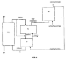
- a flow of metal oxides flows from the air reactor (oxidation reactor R1) in its most oxidized state (0.8 ⁇ X ⁇ 1 and preferably 0.95 ⁇ X ⁇ 1) to the oxygen production reactor (R2) where the material spontaneously releases its oxygen (0.01 ⁇ X 1 1, preferably 0.05 ⁇ X ⁇ ⁇ 0.5) in a carrier gas stream composed (at least partly) of the effluent of the reduction (R 3) (CO2 + H2O) low in oxygen .
- This gaseous effluent is transported to the gasification reactor R4 where it is contacted with a fuel to produce a synthesis gas. This is sent all or part into the reduction reactor (R3), the rest can be upgraded in applications such as Fischer-Tropsch or fuel cell.
- the synthesis gas reacts on contact with the oxygen carrier. This reaction is exothermic and produces a gas almost exclusively composed of carbon dioxide and water vapor.
- the oxygen-carrying solid is in its most reduced form (0 ⁇ x ⁇ 0.3, preferably 0 ⁇ x ⁇ 0.1) and is returned to the oxidation reactor (R1). It is reoxidized in its maximum oxidation state (0.8 ⁇ x ⁇ 1, preferentially 0.95 ⁇ x ⁇ 1) during an exothermic reaction with oxygen in the air.
- the process will also be completed by sulfur treatment units in H 2 S and / or SO 2 form if the fuel contains sulfur.
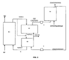
- An advantage of the process according to the invention is to be able to produce synthesis gas under pressure, in an embodiment illustrated by the figure 2 .
- a compressor (C) - turbine (T) to the device for implementing the method according to the invention.
- the flow of oxygen-rich carrier gas (CO2 + H2O + O2) is thus compressed before being introduced into the gasification reactor R4, up to pressures of the order of 40 bars.
- the gasification is then carried out at high pressure (40 bars) and high temperature (up to more than 1000 ° C.).
- the synthesis gas (CO + H2) resulting from the gasification reaction is then also under pressure.
- the synthesis gas returned to the reduction reactor is expanded in a turbine to recover energy.
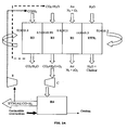
- the transport of the solid between the different reaction zones is carried out by means of a rotating reactor; it is a device usually consisting of a porous cylindrical matrix allowing the passage of gases along its axis of rotation.
- the active phase that is to say the oxygen carrier, is immobilized on this matrix.
- the rotation of the cylindrical reactor is opposite the arrivals of the reactants and the vents.
- the portion of the cylinder comprised between a reactive / vented inlet pair constitutes a reaction zone.
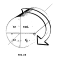
- This figure represents a proposal for spatial distribution of the reactive zones for the rotating reactor system described above. Each zone thus occupies a portion of cylinder contiguous to the next around the axis of rotation of the cylinder.
- the metal oxides that can be used in the process according to the invention can be chosen from the oxides of the transition elements of columns IIIB to IIB (for example Fe, Ti, Ni, Cu, Mo, Mn, Co, V) of the periodic table. singly or in combination, with or without a ceramic-type binder, giving them improved mechanical strength (the binders that may be used are, for example, alumina, spinel aluminates, silica, titanium dioxide, kaolin, ceria zirconia, bentonite or used catalysts.) and possibly a better oxygen transfer capacity (especially for ceria-zirconia type binders). It is also possible to use perovskite, spinel, olivine, hematite, ilmenite and pyrochlore oxides. These are families of simple or mixed oxides whose structure is well determined.
- the metal oxides can be in the form of natural ores (such as ilmenite, hematite for example) or in synthetic form optimized for better oxygen transfer capacity.
- these solids are packaged in the form of powder, Sauter diameter preferably between 30 and 500 microns, and grain density of between 1400 and 8000 kg / m3, preferably between 1400 and 5000 kg / m3.
- the residence time of the metal oxide in the air reactor (R1) depends on the oxidation state and / or reduction of these oxides and can be estimated between 1 and 20 minutes.
- the residence time of the metal oxide in the oxygen generating reactor (R2) depends on the nature of the oxygen-carrying solid and can be estimated between 1 second and 360 seconds.
- the residence time of the metal oxide in the fuel reactor (R3) depends on the nature of the fuel and can be estimated between 1 and 15 minutes.
- the residence time of the metal oxide in the gasification reactor (R4) depends on the nature of the fuel to be gasified and can be estimated between 1 and 20 minutes.
- the residence time of the oxide in the UTI portion of heat recovery depends on the amount of heat to be removed and the nature of the flow used to recover the heat produced.
- the residence time in the UTIL part can be estimated between 1 second and 600 seconds.
- the operating conditions considered at each stage are the following:
- the oxygen-carrying solid chosen is a mixed iron-manganese oxide for which it is considered that up to two percent by weight of the oxygen it contains can be extracted in its most oxidized form.
- oxidized form (Fe 0.6 Mn 0.4 ) 2 O 3
- Cp 1.018 kJ / kg / K (value calculated by the group contribution method - 1 Mostafa et al., Ind. Eng. Chem. Res., Vol. 35, No. 1, 1996 )
- M 158.96 g / mol
- the gasification reaction of the charge is modeled by a minimization of the Gibbs energy whose enthalpy is calculated as a function of the formation energies of the various species present.
- the charge selected in this example is a model C 18 H 30 liquid charge which represents the use of a medium fuel oil.
- the selected charge rate will determine the amount of solids to be circulated in the loop depending on the oxygen requirements of the gasification and combustion operations.
- the present invention makes it possible to modulate the production between the maximization of the thermal energy produced by the process or the maximization of the amount of synthesis gas (Syngaz) leaving the process with respect to the amount of hydrocarbon feedstock introduced.
- the oxygen-carrying solid is flushed with a gas to keep the oxygen partial pressure low.
- This gas also serves as a carrier gas for transporting oxygen in the gasifier. Hot gases from the combustion of synthesis gas on the solid are used here, which are recycled three-quarters.
- This gas is composed of water and carbon dioxide and reaches a temperature of 902 ° C and a flow rate of 11.4 kmol / h.
- the oxygen production reaction is endothermic and consumes 444 kW as heat.
- the exit temperature of the gases is also 897 ° C.
- ⁇ Hr 298 K -41 kJ mol -1 C +2.
- ⁇ Hr 298 K -74.87 kJ mol -1 4.C n H m ⁇ m.CH 4 + (4 n - m ).
- the equilibrium is set and the composition of the synthesis gas is determined by minimizing the Gibbs energy.
- the oxygen carrier gas is compressed before gasification so as to gasify under pressure and obtain a synthesis gas under pressure.
- the energy expenditure for compressing the oxygen carrier gas is estimated at 166 kWe.
- the compression of this gas requires cooling, which is done by water to produce steam in a tube-shell heat exchanger.
- the gasification is carried out at 40 bars, the reactants enter at 905 ° C. and leave at 1058 ° C. because of the exothermicity of the gasification in the presence of oxygen.
- the reaction thus produces a synthesis gas of which 75% is extracted from the process to be recovered, ie 980 kg / h of synthesis gas at 40 bar and 1058 ° C.
- the remaining part of the synthesis gas is intended both to produce the heat necessary for the operation of the process but also, after combustion, to serve as a carrier gas to bring oxygen back to the gasifier.
- This hot and pressurized gas is expanded to generate energy, which, supplemented by that produced by the steam loop upstream of the compressor, must feed the compressor and for the sake of autonomy of the process.
- the energy recovered at the turbine is estimated at 99 kWe plus 127 kWe of the steam loop.
- the energy recovered at the level of this combustion is 0.87 MWth.
- the fluids and solids leave the reduction reactor at a temperature of 902 ° C against a temperature of 897 ° C inlet.
- the heat produced by the process and transported by the solid is recoverable at the outlet of the reduction reactor. For the thermal balance is balanced, it does not value heat at this level.
- the energy supplied to this reactor by the oxidation reaction and to bring the compounds to 1100 ° C is 935 kW. Part of this energy is recoverable by recovering the heat on the depleted airflow, ie 0.17 MWth in the steam loop.
- the synthesis gas has the following composition: Compound mole fraction CO2 0.02 CO 0.53 H2 0.36 H2O 0.03 CH4 0.06
- the excess heat of the process ie 331kWth, is intended for reheating the load which requires 277 kWth.
- the oxygen-carrying solid is flushed with a gas to keep the oxygen partial pressure low.
- This gas also serves as a carrier gas for transporting oxygen in the gasifier. Hot gases from the combustion of synthesis gas on the solid are used here, which are recycled three-quarters.
- This gas is composed of water and carbon dioxide and reaches a temperature of 934 ° C and a flow rate of 169 kmol / h.
- the oxygen production reaction is endothermic and consumes 444 kW as heat.
- the exit temperature of the gases is also 897 ° C.
- ⁇ Hr 298 K -41kJ.mo l -1 C +2 .H 2 ⁇ CH 2
- ⁇ Hr 298 K -74.87kJ.mol -1 4.C n H m ⁇ m.CH 4 + (4 n-m ).
- the equilibrium is set and the composition of the synthesis gas is determined by minimizing the Gibbs energy.
- the oxygen carrier gas is compressed before gasification so as to gasify under pressure and obtain a synthesis gas under pressure.
- the energy expenditure for compressing the oxygen carrier gas is estimated at 1392 kWe.
- the compression of this gas requires cooling, which is done by water to produce steam in a tube-shell type exchanger or 1.69 MWth.
- the gasification takes place at 40 bars, the reactants enter at 827 ° C. and leave at 745 ° C. because of the exothermicity of the gasification in the presence of oxygen.
- the reaction thus produces a synthesis gas from which 0% is extracted from the process to be recovered, namely 6.44 T / h of synthesis gas at 40 bar and 745 ° C which are intended both to produce the heat required for operation of the process but also, after combustion, to serve as carrier gas to bring oxygen back to the gasifier.
- This hot gas and pressure is expanded to generate energy, which must feed the compressor and for the sake of autonomy of the process.
- the energy recovered at the turbine is estimated at 1407 kWe.
- the energy recovered at the level of this combustion is 8.21 MWth.
- the fluids and solids leave the reduction reactor at a temperature of 934 ° C against a temperature of 886 ° C input.
- the heat produced by the process and transported by the solid is recoverable at the outlet of the reduction reactor. Up to 3.6 MWth can be used here.
- the solid is at a temperature of 911 ° C. after heat recovery.
- the oxygen-carrying solid At the outlet of the reduction reactor, the oxygen-carrying solid is in its most reduced state. In the oxidation reactor, it is reoxidized in its most oxidized form in contact with a stream of air.
- Compound Reactor inlet Reactor outlet N2 324 kmol / h at 25 ° C 324 kmol / h at 900 ° C O2 86.2 kmol / h at 25 ° C 1.02 kmol / h (Fe 0.6 Mn 0.4 ) 2 O 3 3390 kmol / h at 911 ° C 3816 kmol / h at 900 ° C ⁇ MnO + 3.Fe 2 MnO 4 ⁇ 85.2 kmol / h at 911 ° C 0 kmol / h
- the energy supplied to this reactor by the oxidation reaction and to bring the compounds to 900 ° C is 0.99 MWth. Part of this energy is recoverable by recovering the heat on the depleted airflow, ie 2.27 MWth.
- This heat includes reheating the load.
Landscapes
- Chemical & Material Sciences (AREA)
- Organic Chemistry (AREA)
- Chemical Kinetics & Catalysis (AREA)
- Inorganic Chemistry (AREA)
- Engineering & Computer Science (AREA)
- Combustion & Propulsion (AREA)
- General Health & Medical Sciences (AREA)
- Health & Medical Sciences (AREA)
- Oil, Petroleum & Natural Gas (AREA)
- Organic Low-Molecular-Weight Compounds And Preparation Thereof (AREA)
- Industrial Gases (AREA)
- Hydrogen, Water And Hydrids (AREA)
- Oxygen, Ozone, And Oxides In General (AREA)
- Carbon And Carbon Compounds (AREA)
Claims (15)
- Verfahren zur Erzeugung von Energie und/oder Synthesegas durch Vergasen mindestens einer flüssigen und/oder festen Charge in einem chemischen Schleifenreaktor, der mindestens vier verschiedene Reaktionsbereiche zur Oxidation. Reduktion, Vergasung und Sauerstofferzeugung umfasst, wobeia) Sauerstoff in einem Reaktionsbereich zur Sauerstofierzeugung R2 erzeugt wird, indem ein Metalloxid in seinem maximalen Oxidationszustand einer Gasatmosphäre mit geringem Sauerstoffpartialdruck ausgesetzt wird, welche aus einem Trägergas besteht, das die Stoffströme aus dem Reduktionsvorgang umfasst;b) der Sauerstoff, welcher in Schritt a) erzeugt wurde, mittels des Trägergases in einem Vergasungsreaktionsbereich R4 befördert wird und die flüssige und/oder feste Charge vergast wird, indem sie mit dem Trägergas, welches mit Sauerstoff angereichert ist, bei hohen Temperaturen in Kontakt gebracht wird, um das Synthesegas CO + H2 zu erzeugen;c) der feste Sauerstoffträger in einem Reduktionsreaktionsbereich R3 reduziert wird, um Sauerstoff freizusetzen, welcher es ermöglicht, das Synthesegas zu oxidieren, wobei die Reduktionsreaktion in dem Reduktionsreaktionsbereich exotherm ist.d) der feste Sauerstoffträger, welcher mindestens teilweise reduziert wurde, um dem System Sauerstoff zu liefern, in einem Oxidationsreaktionsbereich R1 durch Luftkontakt oxidiert wird, um ihn wieder in seinen maximalen Oxidationszustand zu versetzen,und wobei die Wärme, die von den Reaktionen geliefert wird, welche in dem Oxidationsreaktionsbereich R1 und in dem Reduktionsreaktionsbereich R3 ablaufen, dazu genutzt wird, den betrieblichen Energiebedarf des Verfahrens zu decken.
- Verfahren nach Anspruch 1, wobei das Synthesegas in Schritt b) unter Druck erzeugt wird und das erzeugte Synthesegas vor der Reduktion des festen Sauerstoffträgers in Schritt c) entspannt wird.
- Verfahren nach einem der Ansprüche 1 oder 2, wobei mindestens ein Teil des erzeugten Synthesegases innerhalb des Verfahrens verwendet wird, um die Wärme zu liefern, welche für den Betrieb erforderlich ist, und möglicherweise überschüssige Wärme zu erzeugen, die genutzt werden kann.
- Verfahren nach Anspruch 3, wobei mindestens ein Teil des Synthesegases in den Reduktionsreaktionsbereich geleitet wird.
- Verfahren nach Anspruch 4, wobei die Gesamtheit des Synthesegases in den Reduktionsreaktionsbereich geleitet wird.
- Verfahren nach Anspruch 1 bis 4, wobei mindestens ein Teil des erzeugten Synthesegases genutzt wird, wenn es aus dem Vergasungsreaktionsbereich austritt.
- Verfahren nach einem der vorhergehenden Ansprüche, wobei die flüssige und/oder feste Charge aus Kohle, Petrolkoks oder flüssigen Chargen, von denen weniger als 10 % einen Siedepunkt von weniger als 340 °C hat, ausgewählt ist.
- Verfahren nach einem der vorhergehenden Ansprüche, wobei es sich bei den Reaktionsbereichen zur Reduktion, Oxidation und Sauerstofferzeugung um verschiedene Reaktionsbereiche handelt, die in ein und demselben Reaktor gelegen sind.
- Verfahren nach Anspruch 8, wobei es sich bei dem Reaktor um einen Drehreaktor handelt.
- Verfahren nach einem der Ansprüche 1 bis 7, wobei die Reaktionsbereiche zur Reduktion, Oxidation und Sauerstofferzeugung in verschiedenen Reaktoren gelegen sind.
- Verfahren nach einem der vorhergehenden Ansprüche, wobei die anfallende überschüssige Energie durch Wärmeaustausch im Inneren der Reaktionsbereiche oder an den gasförmigen Stoffströmen gewonnen wird.
- Verfahren nach einem der vorhergehenden Ansprüche, wobei- der verbleibende Anteil der Übertragungskapazität X der Metalloxide im Bereich von 0,8 bis 1 liegt, wenn sie aus dem Oxidationsreaktionsbereich R1 austreten;- der verbleibende Anteil der Übertragungskapazität X beim Austritt aus dem Reduktionsreaktionsbereich R3 im Bereich von 0 bis 0,3 liegt;- der Gesamtanteil der Übertragungskapazität ΔX im Sauerstofferzeugungsbereich R2 im Bereich von 0,01 bis 1 liegt.
- Verfahren nach dem Anspruch 12, wobei- der verbleibende Anteil der Übertragungskapazität X der Metalloxide im Bereich von 0,95 bis 1 liegt, wenn sie aus dem Oxidationsreaktionsbereich R1 austreten;- der verbleibende Anteil der Übertragungskapazität X beim Austritt aus dem Reduktionsreaktionsbereich R3 im Bereich von 0 bis 0,1 liegt;- der Gesamtanteil der Übertragungskapazität ΔX im Sauerstofferzeugungsbereich R2 im Bereich von 0,05 bis 0,5 liegt.
- Verwendung des Verfahrens nach einem der vorhergehenden Ansprüche zur Erzeugung von Wärme.
- Verwendung des Verfahrens nach einem der Ansprüche 1 bis 13 zur Erzeugung von Synthesegas, das unter Druck steht.
Priority Applications (1)
| Application Number | Priority Date | Filing Date | Title |
|---|---|---|---|
| PL10290157T PL2246293T3 (pl) | 2009-04-29 | 2010-03-24 | Zintegrowany sposób produkcji energii i/lub gazu syntezowego przez wytwarzanie tlenu in-situ, spalanie i zgazowanie w pętli chemicznej |
Applications Claiming Priority (1)
| Application Number | Priority Date | Filing Date | Title |
|---|---|---|---|
| FR0902096A FR2945034B1 (fr) | 2009-04-29 | 2009-04-29 | Procede integre de production d'energie et/ou de gaz de synthese par production d'oxygene in situ, combustion et gazeification en boucle chimique |
Publications (2)
| Publication Number | Publication Date |
|---|---|
| EP2246293A1 EP2246293A1 (de) | 2010-11-03 |
| EP2246293B1 true EP2246293B1 (de) | 2012-02-08 |
Family
ID=41461886
Family Applications (1)
| Application Number | Title | Priority Date | Filing Date |
|---|---|---|---|
| EP10290157A Not-in-force EP2246293B1 (de) | 2009-04-29 | 2010-03-24 | Integriertes Verfahren zum Generieren von Energie und/oder Synthesegas durch Herstellung von Sauerstoff in situ, Verbrennung und Vergasung in einem chemischen Kreisprozess |
Country Status (7)
| Country | Link |
|---|---|
| US (1) | US8419813B2 (de) |
| EP (1) | EP2246293B1 (de) |
| CN (1) | CN101875483B (de) |
| AT (1) | ATE544727T1 (de) |
| ES (1) | ES2382189T3 (de) |
| FR (1) | FR2945034B1 (de) |
| PL (1) | PL2246293T3 (de) |
Families Citing this family (34)
| Publication number | Priority date | Publication date | Assignee | Title |
|---|---|---|---|---|
| US8877147B2 (en) | 2008-09-26 | 2014-11-04 | The Ohio State University | Conversion of carbonaceous fuels into carbon free energy carriers |
| AU2010292313B2 (en) | 2009-09-08 | 2015-08-20 | The Ohio State University Research Foundation | Integration of reforming/water splitting and electrochemical systems for power generation with integrated carbon capture |
| CA3011693C (en) | 2009-09-08 | 2021-03-09 | The Ohio State University Research Foundation | Synthetic fuels and chemicals production with in-situ co2 capture |
| AU2011326127B2 (en) | 2010-11-08 | 2017-04-20 | Particulate Solid Research, Inc. | Circulating fluidized bed with moving bed downcomers and gas sealing between reactors |
| EP2484971A1 (de) * | 2011-02-04 | 2012-08-08 | Paul Scherrer Institut | Verfahren und System zur Gasifizierung und/oder Verbrennung von Biomasse und/oder Kohle mit mindestens teilweiser Kohlendioxidtrennung |
| CN103635449B (zh) | 2011-05-11 | 2016-09-07 | 俄亥俄州国家创新基金会 | 用来转化燃料的系统 |
| EP2707583B1 (de) | 2011-05-11 | 2019-07-10 | Ohio State Innovation Foundation | Sauerstoffträgermaterialien |
| US20120291351A1 (en) * | 2011-05-16 | 2012-11-22 | Lawrence Bool | Reforming methane and higher hydrocarbons in syngas streams |
| AU2012313348B2 (en) * | 2011-09-23 | 2016-06-02 | The University Of Newcastle | Integrated chemical looping air separation in large-scale oxy-fuel plants |
| RU2602857C2 (ru) * | 2011-12-21 | 2016-11-20 | Линк Энерджи Лтд | Обсадной хвостовик для подземной газификации угля |
| FR2985517B1 (fr) * | 2012-01-11 | 2018-05-18 | Ifp Energies Now | Procede integre de gazeification et combustion indirecte de charges hydrocarbonees solides en boucle chimique |
| US9435184B2 (en) | 2012-06-28 | 2016-09-06 | Carbon Energy Limited | Sacrificial liner linkages for auto-shortening an injection pipe for underground coal gasification |
| US9428978B2 (en) | 2012-06-28 | 2016-08-30 | Carbon Energy Limited | Method for shortening an injection pipe for underground coal gasification |
| JP6048951B2 (ja) * | 2012-08-01 | 2016-12-21 | 国立大学法人 東京大学 | ケミカルループ法における高活性酸素キャリア材料 |
| WO2014085243A1 (en) * | 2012-11-30 | 2014-06-05 | Saudi Arabian Oil Company | Staged chemical looping process with integrated oxygen generation |
| CN103062787B (zh) * | 2012-12-15 | 2015-07-22 | 华中科技大学 | 一种具有自热制氧功能的煤粉燃烧方法和装置 |
| AU2014214982B2 (en) | 2013-02-05 | 2017-11-16 | Ohio State Innovation Foundation | Methods for fuel conversion |
| DE102013202713A1 (de) | 2013-02-20 | 2014-08-21 | Technische Universität Dresden | Vergasungsverfahren zur Erzeugung von Synthesegas mit integrierter Bereitstellung des Vergasungsmittels |
| US9616403B2 (en) | 2013-03-14 | 2017-04-11 | Ohio State Innovation Foundation | Systems and methods for converting carbonaceous fuels |
| US20150238915A1 (en) | 2014-02-27 | 2015-08-27 | Ohio State Innovation Foundation | Systems and methods for partial or complete oxidation of fuels |
| CN105056955B (zh) * | 2015-07-16 | 2017-10-31 | 西北大学 | 一种用于化学循环干气重整的氧载体及其制备方法和应用 |
| EP3429738B1 (de) | 2016-04-12 | 2024-07-17 | Ohio State Innovation Foundation | Chemical-looping-verfahren zur herstellung von synthesegas aus kohlenstoffhaltigen brennstoffen |
| CN106190195B (zh) * | 2016-06-29 | 2019-01-25 | 清华大学 | 一种生物质热解-化学链燃烧制备高纯氢气的装置及方法 |
| AU2018312361B2 (en) | 2017-07-31 | 2021-11-18 | Ohio State Innovation Foundation | Reactor system with unequal reactor assembly operating pressures |
| US10549236B2 (en) | 2018-01-29 | 2020-02-04 | Ohio State Innovation Foundation | Systems, methods and materials for NOx decomposition with metal oxide materials |
| WO2020033500A1 (en) | 2018-08-09 | 2020-02-13 | Ohio State Innovation Foundation | Systems, methods and materials for hydrogen sulfide conversion |
| CN109054900B (zh) * | 2018-08-17 | 2020-12-29 | 新奥科技发展有限公司 | 一种煤气化方法及系统 |
| US10730749B2 (en) * | 2018-11-07 | 2020-08-04 | L'Air Liquide, Société Anonyme pour l'Etude et l'Exploitation des Procédés Georges Claude | Process for integrating a partial oxidation plant with an oxy-combustion plant utilizing a steam turbine |
| CN109745991A (zh) * | 2018-12-13 | 2019-05-14 | 大连海事大学 | 用于煤气化的复合金属氧化物催化剂的制备方法及应用 |
| CA3125491A1 (en) | 2019-01-17 | 2020-07-23 | Ohio State Innovation Foundation | Systems, methods and materials for stable phase syngas generation |
| US11453626B2 (en) | 2019-04-09 | 2022-09-27 | Ohio State Innovation Foundation | Alkene generation using metal sulfide particles |
| WO2021034888A1 (en) | 2019-08-19 | 2021-02-25 | Ohio State Innovation Foundation | Mesoporous support-immobilized metal oxide-based nanoparticles |
| AU2020340961A1 (en) | 2019-09-03 | 2022-03-24 | Ohio State Innovation Foundation | Redox reaction facilitated carbon dioxide capture from flue gas and conversion to carbon monoxide |
| US11286832B1 (en) * | 2021-04-07 | 2022-03-29 | Scuderi Group, Inc. | Bottoming cycle power system |
Family Cites Families (10)
| Publication number | Priority date | Publication date | Assignee | Title |
|---|---|---|---|---|
| JPH1162622A (ja) * | 1997-08-22 | 1999-03-05 | Toshiba Corp | 石炭ガス化複合発電設備およびその運転方法 |
| CA2340822C (en) * | 2000-03-17 | 2010-08-03 | Snamprogetti S.P.A. | Process for the production of hydrogen |
| US6682714B2 (en) * | 2001-03-06 | 2004-01-27 | Alchemix Corporation | Method for the production of hydrogen gas |
| FR2850156B1 (fr) | 2003-01-16 | 2005-12-30 | Alstom Switzerland Ltd | Installation de combustion avec recuperation de co2 |
| US7767191B2 (en) * | 2003-12-11 | 2010-08-03 | The Ohio State University | Combustion looping using composite oxygen carriers |
| FR2891609B1 (fr) | 2005-10-04 | 2007-11-23 | Inst Francais Du Petrole | Procede d'oxy-combustion permettant la capture de la totalite du dioxyde de carbone produit. |
| CA2636325C (en) * | 2006-01-12 | 2015-04-28 | The Ohio State University | Systems and methods of converting fuel |
| US7824574B2 (en) * | 2006-09-21 | 2010-11-02 | Eltron Research & Development | Cyclic catalytic upgrading of chemical species using metal oxide materials |
| US20090020405A1 (en) * | 2007-07-20 | 2009-01-22 | Foster Wheeler Energy Corporation | Method of and a plant for combusting carbonaceous fuel by using a solid oxygen carrier |
| US9122260B2 (en) * | 2008-03-03 | 2015-09-01 | Alstom Technology Ltd | Integrated controls design optimization |
-
2009
- 2009-04-29 FR FR0902096A patent/FR2945034B1/fr not_active Expired - Fee Related
-
2010
- 2010-03-24 PL PL10290157T patent/PL2246293T3/pl unknown
- 2010-03-24 EP EP10290157A patent/EP2246293B1/de not_active Not-in-force
- 2010-03-24 ES ES10290157T patent/ES2382189T3/es active Active
- 2010-03-24 AT AT10290157T patent/ATE544727T1/de active
- 2010-04-28 CN CN201010174654.8A patent/CN101875483B/zh not_active Expired - Fee Related
- 2010-04-29 US US12/769,855 patent/US8419813B2/en not_active Expired - Fee Related
Also Published As
| Publication number | Publication date |
|---|---|
| CN101875483B (zh) | 2014-01-01 |
| CN101875483A (zh) | 2010-11-03 |
| PL2246293T3 (pl) | 2012-07-31 |
| FR2945034A1 (fr) | 2010-11-05 |
| US8419813B2 (en) | 2013-04-16 |
| ES2382189T3 (es) | 2012-06-06 |
| US20100299997A1 (en) | 2010-12-02 |
| FR2945034B1 (fr) | 2012-06-08 |
| ATE544727T1 (de) | 2012-02-15 |
| EP2246293A1 (de) | 2010-11-03 |
Similar Documents
| Publication | Publication Date | Title |
|---|---|---|
| EP2246293B1 (de) | Integriertes Verfahren zum Generieren von Energie und/oder Synthesegas durch Herstellung von Sauerstoff in situ, Verbrennung und Vergasung in einem chemischen Kreisprozess | |
| EP2391695B1 (de) | Integriertes oxidations-, reduktions- und vergasungsverfahren zur herstellung von synthesegas und energie in einem chemischen kreislauf | |
| EP2802638B1 (de) | Integriertes gasifizierungsverfahren in einem chemischen kreislauf und indirekte verbrennung fester kohlenwasserstoffeinsätze | |
| EP3097051B1 (de) | Sauergasverbrennung unter verwendung von in-situ-sauerstoffproduktion und chemical-looping-verbrennung | |
| EP2142622B1 (de) | Verfahren zur erzeugung eines gereinigten synthesegases aus einer biomasse mit einem der partiellen oxidierung vorgelagerten reinigungsschritt | |
| EP2392545A1 (de) | Verfahren und Anlage für die Sauerstofferzeugung in einem chemischen Kreislauf im Wirbelbett | |
| CA2737663A1 (fr) | Procede de production d'energie et capture du co2 | |
| EP3169756B1 (de) | Calciumsulfatschleifungszyklen zur sauergasverbrennung und elektrizitätserzeugung | |
| WO2022229838A1 (en) | Process for producing hydrogen from a hydrocarbon feedstock | |
| CN1969150B (zh) | 最小化消耗氧的能量转换方法 | |
| EP3230414B1 (de) | Verfahren und anlage für einen chemischen redoxkreislauf eines kohlenwasserstoffgases mit einer katalytischen dampfreformierung als zwischenschritt | |
| WO2014068205A1 (fr) | Procédé de combustion en boucle chimique utilisant une masse oxydo-reductrice comprenant de la pyrolusite enrichie avec de l'oxyde de nickel | |
| EP2491306A1 (de) | Verfahren und vorrichtung zur stromerzeugung anhand der oxidation von kraftstoff in einem chemischen kreislauf | |
| FR2960943A1 (fr) | Procede integre d'oxycombustion et de production d'oxygene par boucle chimique | |
| EP4374109A1 (de) | Clc-anlage und verfahren mit rückgewinnung von durch einen sauerstoffträger erzeugtem gasförmigem sauerstoff | |
| FR2956656A1 (fr) | Procede de production de gaz de synthese | |
| WO2014044940A1 (fr) | Procédé de reduction du dioxyde de carbone en monoxyde de carbone par des oxydes de vanadium | |
| WO2014118453A1 (fr) | Masse active d'oxydo-reduction comprenant de la pyrolusite enrichie en nickel et un compose a structure spinelle et utilisation dans un procédé de combustion en boucle chimique | |
| EP3230416B1 (de) | Anlage und verfahren zur chemical-looping-oxidation-combustion mit oxidationsreduktion eines gasförmigen kohlenwasserstoffeinsatzstoffes mit katalytischer vorreformierung des einsatzstoffes | |
| EP4700100A1 (de) | Verfahren und system zur herstellung von synthetischem öl | |
| CA2861050A1 (fr) | Procede integre de gazeification et combustion indirecte de charges hydrocarbonees solides en boucle chimique |
Legal Events
| Date | Code | Title | Description |
|---|---|---|---|
| PUAI | Public reference made under article 153(3) epc to a published international application that has entered the european phase |
Free format text: ORIGINAL CODE: 0009012 |
|
| AK | Designated contracting states |
Kind code of ref document: A1 Designated state(s): AT BE BG CH CY CZ DE DK EE ES FI FR GB GR HR HU IE IS IT LI LT LU LV MC MK MT NL NO PL PT RO SE SI SK SM TR |
|
| AX | Request for extension of the european patent |
Extension state: AL BA ME RS |
|
| 17P | Request for examination filed |
Effective date: 20110503 |
|
| GRAP | Despatch of communication of intention to grant a patent |
Free format text: ORIGINAL CODE: EPIDOSNIGR1 |
|
| RIC1 | Information provided on ipc code assigned before grant |
Ipc: C01B 13/02 20060101ALI20110825BHEP Ipc: C10J 3/00 20060101ALI20110825BHEP Ipc: C01B 3/46 20060101ALI20110825BHEP Ipc: C01B 3/36 20060101AFI20110825BHEP |
|
| GRAJ | Information related to disapproval of communication of intention to grant by the applicant or resumption of examination proceedings by the epo deleted |
Free format text: ORIGINAL CODE: EPIDOSDIGR1 |
|
| GRAP | Despatch of communication of intention to grant a patent |
Free format text: ORIGINAL CODE: EPIDOSNIGR1 |
|
| GRAS | Grant fee paid |
Free format text: ORIGINAL CODE: EPIDOSNIGR3 |
|
| GRAA | (expected) grant |
Free format text: ORIGINAL CODE: 0009210 |
|
| AK | Designated contracting states |
Kind code of ref document: B1 Designated state(s): AT BE BG CH CY CZ DE DK EE ES FI FR GB GR HR HU IE IS IT LI LT LU LV MC MK MT NL NO PL PT RO SE SI SK SM TR |
|
| REG | Reference to a national code |
Ref country code: GB Ref legal event code: FG4D Free format text: NOT ENGLISH |
|
| REG | Reference to a national code |
Ref country code: AT Ref legal event code: REF Ref document number: 544727 Country of ref document: AT Kind code of ref document: T Effective date: 20120215 Ref country code: CH Ref legal event code: EP |
|
| REG | Reference to a national code |
Ref country code: DE Ref legal event code: R096 Ref document number: 602010000833 Country of ref document: DE Effective date: 20120405 |
|
| REG | Reference to a national code |
Ref country code: NL Ref legal event code: T3 |
|
| REG | Reference to a national code |
Ref country code: ES Ref legal event code: FG2A Ref document number: 2382189 Country of ref document: ES Kind code of ref document: T3 Effective date: 20120606 |
|
| LTIE | Lt: invalidation of european patent or patent extension |
Effective date: 20120208 |
|
| PG25 | Lapsed in a contracting state [announced via postgrant information from national office to epo] |
Ref country code: NO Free format text: LAPSE BECAUSE OF FAILURE TO SUBMIT A TRANSLATION OF THE DESCRIPTION OR TO PAY THE FEE WITHIN THE PRESCRIBED TIME-LIMIT Effective date: 20120508 Ref country code: IS Free format text: LAPSE BECAUSE OF FAILURE TO SUBMIT A TRANSLATION OF THE DESCRIPTION OR TO PAY THE FEE WITHIN THE PRESCRIBED TIME-LIMIT Effective date: 20120608 Ref country code: HR Free format text: LAPSE BECAUSE OF FAILURE TO SUBMIT A TRANSLATION OF THE DESCRIPTION OR TO PAY THE FEE WITHIN THE PRESCRIBED TIME-LIMIT Effective date: 20120208 Ref country code: LT Free format text: LAPSE BECAUSE OF FAILURE TO SUBMIT A TRANSLATION OF THE DESCRIPTION OR TO PAY THE FEE WITHIN THE PRESCRIBED TIME-LIMIT Effective date: 20120208 |
|
| REG | Reference to a national code |
Ref country code: PL Ref legal event code: T3 |
|
| REG | Reference to a national code |
Ref country code: IE Ref legal event code: FD4D |
|
| PG25 | Lapsed in a contracting state [announced via postgrant information from national office to epo] |
Ref country code: FI Free format text: LAPSE BECAUSE OF FAILURE TO SUBMIT A TRANSLATION OF THE DESCRIPTION OR TO PAY THE FEE WITHIN THE PRESCRIBED TIME-LIMIT Effective date: 20120208 Ref country code: PT Free format text: LAPSE BECAUSE OF FAILURE TO SUBMIT A TRANSLATION OF THE DESCRIPTION OR TO PAY THE FEE WITHIN THE PRESCRIBED TIME-LIMIT Effective date: 20120608 Ref country code: LV Free format text: LAPSE BECAUSE OF FAILURE TO SUBMIT A TRANSLATION OF THE DESCRIPTION OR TO PAY THE FEE WITHIN THE PRESCRIBED TIME-LIMIT Effective date: 20120208 Ref country code: GR Free format text: LAPSE BECAUSE OF FAILURE TO SUBMIT A TRANSLATION OF THE DESCRIPTION OR TO PAY THE FEE WITHIN THE PRESCRIBED TIME-LIMIT Effective date: 20120509 |
|
| REG | Reference to a national code |
Ref country code: AT Ref legal event code: MK05 Ref document number: 544727 Country of ref document: AT Kind code of ref document: T Effective date: 20120208 |
|
| PG25 | Lapsed in a contracting state [announced via postgrant information from national office to epo] |
Ref country code: CY Free format text: LAPSE BECAUSE OF FAILURE TO SUBMIT A TRANSLATION OF THE DESCRIPTION OR TO PAY THE FEE WITHIN THE PRESCRIBED TIME-LIMIT Effective date: 20120208 |
|
| BERE | Be: lapsed |
Owner name: IFP ENERGIES NOUVELLES Effective date: 20120331 |
|
| PG25 | Lapsed in a contracting state [announced via postgrant information from national office to epo] |
Ref country code: IE Free format text: LAPSE BECAUSE OF FAILURE TO SUBMIT A TRANSLATION OF THE DESCRIPTION OR TO PAY THE FEE WITHIN THE PRESCRIBED TIME-LIMIT Effective date: 20120208 Ref country code: SI Free format text: LAPSE BECAUSE OF FAILURE TO SUBMIT A TRANSLATION OF THE DESCRIPTION OR TO PAY THE FEE WITHIN THE PRESCRIBED TIME-LIMIT Effective date: 20120208 Ref country code: SE Free format text: LAPSE BECAUSE OF FAILURE TO SUBMIT A TRANSLATION OF THE DESCRIPTION OR TO PAY THE FEE WITHIN THE PRESCRIBED TIME-LIMIT Effective date: 20120208 Ref country code: EE Free format text: LAPSE BECAUSE OF FAILURE TO SUBMIT A TRANSLATION OF THE DESCRIPTION OR TO PAY THE FEE WITHIN THE PRESCRIBED TIME-LIMIT Effective date: 20120208 Ref country code: RO Free format text: LAPSE BECAUSE OF FAILURE TO SUBMIT A TRANSLATION OF THE DESCRIPTION OR TO PAY THE FEE WITHIN THE PRESCRIBED TIME-LIMIT Effective date: 20120208 Ref country code: CZ Free format text: LAPSE BECAUSE OF FAILURE TO SUBMIT A TRANSLATION OF THE DESCRIPTION OR TO PAY THE FEE WITHIN THE PRESCRIBED TIME-LIMIT Effective date: 20120208 Ref country code: MC Free format text: LAPSE BECAUSE OF NON-PAYMENT OF DUE FEES Effective date: 20120331 Ref country code: DK Free format text: LAPSE BECAUSE OF FAILURE TO SUBMIT A TRANSLATION OF THE DESCRIPTION OR TO PAY THE FEE WITHIN THE PRESCRIBED TIME-LIMIT Effective date: 20120208 |
|
| PG25 | Lapsed in a contracting state [announced via postgrant information from national office to epo] |
Ref country code: SK Free format text: LAPSE BECAUSE OF FAILURE TO SUBMIT A TRANSLATION OF THE DESCRIPTION OR TO PAY THE FEE WITHIN THE PRESCRIBED TIME-LIMIT Effective date: 20120208 |
|
| PLBE | No opposition filed within time limit |
Free format text: ORIGINAL CODE: 0009261 |
|
| STAA | Information on the status of an ep patent application or granted ep patent |
Free format text: STATUS: NO OPPOSITION FILED WITHIN TIME LIMIT |
|
| 26N | No opposition filed |
Effective date: 20121109 |
|
| PG25 | Lapsed in a contracting state [announced via postgrant information from national office to epo] |
Ref country code: BE Free format text: LAPSE BECAUSE OF NON-PAYMENT OF DUE FEES Effective date: 20120331 Ref country code: AT Free format text: LAPSE BECAUSE OF FAILURE TO SUBMIT A TRANSLATION OF THE DESCRIPTION OR TO PAY THE FEE WITHIN THE PRESCRIBED TIME-LIMIT Effective date: 20120208 |
|
| PG25 | Lapsed in a contracting state [announced via postgrant information from national office to epo] |
Ref country code: MK Free format text: LAPSE BECAUSE OF FAILURE TO SUBMIT A TRANSLATION OF THE DESCRIPTION OR TO PAY THE FEE WITHIN THE PRESCRIBED TIME-LIMIT Effective date: 20120208 |
|
| REG | Reference to a national code |
Ref country code: DE Ref legal event code: R097 Ref document number: 602010000833 Country of ref document: DE Effective date: 20121109 |
|
| PG25 | Lapsed in a contracting state [announced via postgrant information from national office to epo] |
Ref country code: MT Free format text: LAPSE BECAUSE OF FAILURE TO SUBMIT A TRANSLATION OF THE DESCRIPTION OR TO PAY THE FEE WITHIN THE PRESCRIBED TIME-LIMIT Effective date: 20120208 Ref country code: BG Free format text: LAPSE BECAUSE OF FAILURE TO SUBMIT A TRANSLATION OF THE DESCRIPTION OR TO PAY THE FEE WITHIN THE PRESCRIBED TIME-LIMIT Effective date: 20120508 |
|
| PG25 | Lapsed in a contracting state [announced via postgrant information from national office to epo] |
Ref country code: TR Free format text: LAPSE BECAUSE OF FAILURE TO SUBMIT A TRANSLATION OF THE DESCRIPTION OR TO PAY THE FEE WITHIN THE PRESCRIBED TIME-LIMIT Effective date: 20120208 |
|
| PG25 | Lapsed in a contracting state [announced via postgrant information from national office to epo] |
Ref country code: LU Free format text: LAPSE BECAUSE OF NON-PAYMENT OF DUE FEES Effective date: 20120324 Ref country code: SM Free format text: LAPSE BECAUSE OF FAILURE TO SUBMIT A TRANSLATION OF THE DESCRIPTION OR TO PAY THE FEE WITHIN THE PRESCRIBED TIME-LIMIT Effective date: 20120208 |
|
| PG25 | Lapsed in a contracting state [announced via postgrant information from national office to epo] |
Ref country code: HU Free format text: LAPSE BECAUSE OF FAILURE TO SUBMIT A TRANSLATION OF THE DESCRIPTION OR TO PAY THE FEE WITHIN THE PRESCRIBED TIME-LIMIT Effective date: 20100324 |
|
| REG | Reference to a national code |
Ref country code: CH Ref legal event code: PL |
|
| PG25 | Lapsed in a contracting state [announced via postgrant information from national office to epo] |
Ref country code: LI Free format text: LAPSE BECAUSE OF NON-PAYMENT OF DUE FEES Effective date: 20140331 Ref country code: CH Free format text: LAPSE BECAUSE OF NON-PAYMENT OF DUE FEES Effective date: 20140331 |
|
| REG | Reference to a national code |
Ref country code: FR Ref legal event code: PLFP Year of fee payment: 7 |
|
| REG | Reference to a national code |
Ref country code: FR Ref legal event code: PLFP Year of fee payment: 8 |
|
| PGFP | Annual fee paid to national office [announced via postgrant information from national office to epo] |
Ref country code: FR Payment date: 20170327 Year of fee payment: 8 Ref country code: NL Payment date: 20170323 Year of fee payment: 8 |
|
| PGFP | Annual fee paid to national office [announced via postgrant information from national office to epo] |
Ref country code: GB Payment date: 20170323 Year of fee payment: 8 |
|
| PGFP | Annual fee paid to national office [announced via postgrant information from national office to epo] |
Ref country code: IT Payment date: 20170331 Year of fee payment: 8 |
|
| PGFP | Annual fee paid to national office [announced via postgrant information from national office to epo] |
Ref country code: DE Payment date: 20170403 Year of fee payment: 8 |
|
| PGFP | Annual fee paid to national office [announced via postgrant information from national office to epo] |
Ref country code: ES Payment date: 20170328 Year of fee payment: 8 |
|
| PGFP | Annual fee paid to national office [announced via postgrant information from national office to epo] |
Ref country code: PL Payment date: 20180221 Year of fee payment: 9 |
|
| REG | Reference to a national code |
Ref country code: DE Ref legal event code: R119 Ref document number: 602010000833 Country of ref document: DE |
|
| REG | Reference to a national code |
Ref country code: NL Ref legal event code: MM Effective date: 20180401 |
|
| GBPC | Gb: european patent ceased through non-payment of renewal fee |
Effective date: 20180324 |
|
| PG25 | Lapsed in a contracting state [announced via postgrant information from national office to epo] |
Ref country code: NL Free format text: LAPSE BECAUSE OF NON-PAYMENT OF DUE FEES Effective date: 20180401 |
|
| PG25 | Lapsed in a contracting state [announced via postgrant information from national office to epo] |
Ref country code: DE Free format text: LAPSE BECAUSE OF NON-PAYMENT OF DUE FEES Effective date: 20181002 |
|
| PG25 | Lapsed in a contracting state [announced via postgrant information from national office to epo] |
Ref country code: GB Free format text: LAPSE BECAUSE OF NON-PAYMENT OF DUE FEES Effective date: 20180324 Ref country code: IT Free format text: LAPSE BECAUSE OF NON-PAYMENT OF DUE FEES Effective date: 20180324 |
|
| PG25 | Lapsed in a contracting state [announced via postgrant information from national office to epo] |
Ref country code: FR Free format text: LAPSE BECAUSE OF NON-PAYMENT OF DUE FEES Effective date: 20180331 |
|
| REG | Reference to a national code |
Ref country code: ES Ref legal event code: FD2A Effective date: 20190911 |
|
| PG25 | Lapsed in a contracting state [announced via postgrant information from national office to epo] |
Ref country code: ES Free format text: LAPSE BECAUSE OF NON-PAYMENT OF DUE FEES Effective date: 20180325 |
|
| PG25 | Lapsed in a contracting state [announced via postgrant information from national office to epo] |
Ref country code: PL Free format text: LAPSE BECAUSE OF NON-PAYMENT OF DUE FEES Effective date: 20190324 |