EP2246293B1 - Integrated process for production of energy and/or synthesis gas by production of oxygen in situ, combustion and gasification in a chemical cycle - Google Patents
Integrated process for production of energy and/or synthesis gas by production of oxygen in situ, combustion and gasification in a chemical cycle Download PDFInfo
- Publication number
- EP2246293B1 EP2246293B1 EP10290157A EP10290157A EP2246293B1 EP 2246293 B1 EP2246293 B1 EP 2246293B1 EP 10290157 A EP10290157 A EP 10290157A EP 10290157 A EP10290157 A EP 10290157A EP 2246293 B1 EP2246293 B1 EP 2246293B1
- Authority
- EP
- European Patent Office
- Prior art keywords
- oxygen
- zone
- reduction
- gasification
- oxidation
- Prior art date
- Legal status (The legal status is an assumption and is not a legal conclusion. Google has not performed a legal analysis and makes no representation as to the accuracy of the status listed.)
- Not-in-force
Links
Images
Classifications
-
- C—CHEMISTRY; METALLURGY
- C01—INORGANIC CHEMISTRY
- C01B—NON-METALLIC ELEMENTS; COMPOUNDS THEREOF; METALLOIDS OR COMPOUNDS THEREOF NOT COVERED BY SUBCLASS C01C
- C01B13/00—Oxygen; Ozone; Oxides or hydroxides in general
- C01B13/02—Preparation of oxygen
- C01B13/0203—Preparation of oxygen from inorganic compounds
-
- C—CHEMISTRY; METALLURGY
- C01—INORGANIC CHEMISTRY
- C01B—NON-METALLIC ELEMENTS; COMPOUNDS THEREOF; METALLOIDS OR COMPOUNDS THEREOF NOT COVERED BY SUBCLASS C01C
- C01B3/00—Hydrogen; Gaseous mixtures containing hydrogen; Separation of hydrogen from mixtures containing it; Purification of hydrogen
- C01B3/02—Production of hydrogen or of gaseous mixtures containing a substantial proportion of hydrogen
- C01B3/32—Production of hydrogen or of gaseous mixtures containing a substantial proportion of hydrogen by reaction of gaseous or liquid organic compounds with gasifying agents, e.g. water, carbon dioxide, air
- C01B3/34—Production of hydrogen or of gaseous mixtures containing a substantial proportion of hydrogen by reaction of gaseous or liquid organic compounds with gasifying agents, e.g. water, carbon dioxide, air by reaction of hydrocarbons with gasifying agents
- C01B3/36—Production of hydrogen or of gaseous mixtures containing a substantial proportion of hydrogen by reaction of gaseous or liquid organic compounds with gasifying agents, e.g. water, carbon dioxide, air by reaction of hydrocarbons with gasifying agents using oxygen or mixtures containing oxygen as gasifying agents
-
- C—CHEMISTRY; METALLURGY
- C01—INORGANIC CHEMISTRY
- C01B—NON-METALLIC ELEMENTS; COMPOUNDS THEREOF; METALLOIDS OR COMPOUNDS THEREOF NOT COVERED BY SUBCLASS C01C
- C01B3/00—Hydrogen; Gaseous mixtures containing hydrogen; Separation of hydrogen from mixtures containing it; Purification of hydrogen
- C01B3/02—Production of hydrogen or of gaseous mixtures containing a substantial proportion of hydrogen
- C01B3/32—Production of hydrogen or of gaseous mixtures containing a substantial proportion of hydrogen by reaction of gaseous or liquid organic compounds with gasifying agents, e.g. water, carbon dioxide, air
- C01B3/34—Production of hydrogen or of gaseous mixtures containing a substantial proportion of hydrogen by reaction of gaseous or liquid organic compounds with gasifying agents, e.g. water, carbon dioxide, air by reaction of hydrocarbons with gasifying agents
- C01B3/46—Production of hydrogen or of gaseous mixtures containing a substantial proportion of hydrogen by reaction of gaseous or liquid organic compounds with gasifying agents, e.g. water, carbon dioxide, air by reaction of hydrocarbons with gasifying agents using discontinuously preheated non-moving solid materials, e.g. blast and run
-
- C—CHEMISTRY; METALLURGY
- C10—PETROLEUM, GAS OR COKE INDUSTRIES; TECHNICAL GASES CONTAINING CARBON MONOXIDE; FUELS; LUBRICANTS; PEAT
- C10J—PRODUCTION OF PRODUCER GAS, WATER-GAS, SYNTHESIS GAS FROM SOLID CARBONACEOUS MATERIAL, OR MIXTURES CONTAINING THESE GASES; CARBURETTING AIR OR OTHER GASES
- C10J3/00—Production of combustible gases containing carbon monoxide from solid carbonaceous fuels
- C10J3/72—Other features
- C10J3/725—Redox processes
-
- C—CHEMISTRY; METALLURGY
- C01—INORGANIC CHEMISTRY
- C01B—NON-METALLIC ELEMENTS; COMPOUNDS THEREOF; METALLOIDS OR COMPOUNDS THEREOF NOT COVERED BY SUBCLASS C01C
- C01B2203/00—Integrated processes for the production of hydrogen or synthesis gas
- C01B2203/02—Processes for making hydrogen or synthesis gas
- C01B2203/025—Processes for making hydrogen or synthesis gas containing a partial oxidation step
- C01B2203/0255—Processes for making hydrogen or synthesis gas containing a partial oxidation step containing a non-catalytic partial oxidation step
-
- C—CHEMISTRY; METALLURGY
- C10—PETROLEUM, GAS OR COKE INDUSTRIES; TECHNICAL GASES CONTAINING CARBON MONOXIDE; FUELS; LUBRICANTS; PEAT
- C10J—PRODUCTION OF PRODUCER GAS, WATER-GAS, SYNTHESIS GAS FROM SOLID CARBONACEOUS MATERIAL, OR MIXTURES CONTAINING THESE GASES; CARBURETTING AIR OR OTHER GASES
- C10J2300/00—Details of gasification processes
- C10J2300/09—Details of the feed, e.g. feeding of spent catalyst, inert gas or halogens
- C10J2300/0953—Gasifying agents
- C10J2300/0959—Oxygen
-
- C—CHEMISTRY; METALLURGY
- C10—PETROLEUM, GAS OR COKE INDUSTRIES; TECHNICAL GASES CONTAINING CARBON MONOXIDE; FUELS; LUBRICANTS; PEAT
- C10J—PRODUCTION OF PRODUCER GAS, WATER-GAS, SYNTHESIS GAS FROM SOLID CARBONACEOUS MATERIAL, OR MIXTURES CONTAINING THESE GASES; CARBURETTING AIR OR OTHER GASES
- C10J2300/00—Details of gasification processes
- C10J2300/18—Details of the gasification process, e.g. loops, autothermal operation
- C10J2300/1807—Recycle loops, e.g. gas, solids, heating medium, water
-
- Y—GENERAL TAGGING OF NEW TECHNOLOGICAL DEVELOPMENTS; GENERAL TAGGING OF CROSS-SECTIONAL TECHNOLOGIES SPANNING OVER SEVERAL SECTIONS OF THE IPC; TECHNICAL SUBJECTS COVERED BY FORMER USPC CROSS-REFERENCE ART COLLECTIONS [XRACs] AND DIGESTS
- Y02—TECHNOLOGIES OR APPLICATIONS FOR MITIGATION OR ADAPTATION AGAINST CLIMATE CHANGE
- Y02P—CLIMATE CHANGE MITIGATION TECHNOLOGIES IN THE PRODUCTION OR PROCESSING OF GOODS
- Y02P20/00—Technologies relating to chemical industry
- Y02P20/10—Process efficiency
Definitions
- the oxyfuel combustion units have the advantage of producing combustion fumes that are free of nitrogen from the combustion air since the combustion is made from pure oxygen.
- This oxygen is produced by an air separation unit (ASU).
- a disadvantage of this mode of combustion and ASUs in particular is their high energy consumption and their high investment cost which greatly increases the overall cost of capture.
- Chemical loop combustion has significant potential for energy efficiency and cost reduction. This process avoids the energy penalty related to the separation of oxygen from the air. It is based on the oxygen transfer capacity of certain materials such as metal oxides.
- An air reactor is used to oxidize the oxygen carriers prepared as fine particles which are then transferred to a fuel reactor where they are reduced by the combustion of the fuel. This process is generally carried out on a pilot scale in the form of two fluidized beds exchanging solids streams: the air reactor then being a fast fluidization type reactor at the top of which the flow of oxygen depleted air and the particles are separated.
- the document W02007082089A2 consists of a three-step process that highlights the use of metal oxide recirculation for hydrogen production.
- a first reactor a total combustion of the fuel makes it possible to produce CO2, H2O.
- the production of hydrogen is carried out by reoxidation of the metal oxide with steam.
- This embodiment imposes significant steam flows and therefore the need to heat and evaporate a large amount of water before introduction into the oxidation reactor, resulting in a limiting energy balance.
- Hydrogen production can also be carried out by gasification: the patent application WO2008036902A2 describes for example a hydrocarbon gasification process which is carried out in a conventional arrangement of two reaction zones.
- Some oxygen carriers have the ability to spontaneously release some of their oxygen in a low oxygen environment.
- an oxygen production reactor within a chemical loop makes it possible to gasify the fuel with a mixture enriched with oxygen avoiding direct contact solid - solid fuel. This avoids the need for solid-solid separation equipment.
- This particular configuration also has the advantage of improving the energy balance of the gasification step, which is very endothermic in the absence of oxygen, but also of accelerating the reactions since the reactions involved are reactions between solid and gas (and no longer between solid and solid).
- the process according to the invention is particularly advantageous for the gasification of heavy charges.
- the synthesis gas is produced under pressure in step b) and the expansion gas produced before the reduction of the oxygen-carrying solid in step c) is carried out.
- At least a portion of the synthesis gas produced can be used within the process, to provide the heat necessary for operation and possibly produce surplus heat that can be upgraded.
- At least a part of the synthesis gas is sent to the reduction reaction zone, or even the totality of the synthesis gas.
- At least a portion of the synthesis gas produced can be recovered at the outlet of the gasification reaction zone.
- the liquid and / or solid feed may be selected from coal, petroleum coke or liquid feeds of which less than 10% has a boiling point below 340 ° C.
- reaction zones of reduction, oxidation and oxygen production are separate reaction zones located in the same reactor.
- the reactor can then be a rotary reactor.
- reaction zones of reduction, oxidation and oxygen production are located in separate reactors.
- Exportable surplus energy can be recovered by heat exchange within the reaction zones or on the gaseous effluents.
- the invention relates to the use of the method described above for the production of heat.
- the invention also relates to the use of the method described above for the production of synthesis gas under pressure.
- oxygen carrier solid any metal oxide for which the degree of oxidation of the metal can vary, depending on its oxygen content. This variation can be exploited to transport oxygen between two reactive media.
- an oxidizing medium rich in oxygen O 2 the degree of oxidation of the metal is maximized, that is to say that the oxygen content of the solid is maximized.
- a medium low in oxygen O 2 the previously oxidized solid will spontaneously release some of its oxygen and see its oxidation state decrease with respect to its oxidation state when it was completely oxidized.
- oxygen carrier solid is also defined by its reversible oxygen transfer capacity, that is to say the amount of oxygen that this carrier can exchange. with the reaction medium between its most oxidized and the least oxidized state, and this reversibly.
- X is defined as the fraction of the total oxygen transfer capacity remaining in the oxide.
- ⁇ X is defined as a fraction of the total oxygen transfer capacity.
- reactor will be used simply to denote a reaction zone comprising one or more reactors in which reactions of the same type take place.
- a flow of metal oxides flows from the air reactor (oxidation reactor R1) in its most oxidized state (0.8 ⁇ X ⁇ 1 and preferably 0.95 ⁇ X ⁇ 1) to the oxygen production reactor (R2) where the material spontaneously releases its oxygen (0.01 ⁇ X 1 1, preferably 0.05 ⁇ X ⁇ ⁇ 0.5) in a carrier gas stream composed (at least partly) of the effluent of the reduction (R 3) (CO2 + H2O) low in oxygen .
- This gaseous effluent is transported to the gasification reactor R4 where it is contacted with a fuel to produce a synthesis gas. This is sent all or part into the reduction reactor (R3), the rest can be upgraded in applications such as Fischer-Tropsch or fuel cell.
- the synthesis gas reacts on contact with the oxygen carrier. This reaction is exothermic and produces a gas almost exclusively composed of carbon dioxide and water vapor.
- the oxygen-carrying solid is in its most reduced form (0 ⁇ x ⁇ 0.3, preferably 0 ⁇ x ⁇ 0.1) and is returned to the oxidation reactor (R1). It is reoxidized in its maximum oxidation state (0.8 ⁇ x ⁇ 1, preferentially 0.95 ⁇ x ⁇ 1) during an exothermic reaction with oxygen in the air.
- the process will also be completed by sulfur treatment units in H 2 S and / or SO 2 form if the fuel contains sulfur.
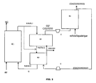
- An advantage of the process according to the invention is to be able to produce synthesis gas under pressure, in an embodiment illustrated by the figure 2 .
- a compressor (C) - turbine (T) to the device for implementing the method according to the invention.
- the flow of oxygen-rich carrier gas (CO2 + H2O + O2) is thus compressed before being introduced into the gasification reactor R4, up to pressures of the order of 40 bars.
- the gasification is then carried out at high pressure (40 bars) and high temperature (up to more than 1000 ° C.).
- the synthesis gas (CO + H2) resulting from the gasification reaction is then also under pressure.
- the synthesis gas returned to the reduction reactor is expanded in a turbine to recover energy.
- the transport of the solid between the different reaction zones is carried out by means of a rotating reactor; it is a device usually consisting of a porous cylindrical matrix allowing the passage of gases along its axis of rotation.
- the active phase that is to say the oxygen carrier, is immobilized on this matrix.
- the rotation of the cylindrical reactor is opposite the arrivals of the reactants and the vents.
- the portion of the cylinder comprised between a reactive / vented inlet pair constitutes a reaction zone.
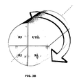
- This figure represents a proposal for spatial distribution of the reactive zones for the rotating reactor system described above. Each zone thus occupies a portion of cylinder contiguous to the next around the axis of rotation of the cylinder.
- the metal oxides that can be used in the process according to the invention can be chosen from the oxides of the transition elements of columns IIIB to IIB (for example Fe, Ti, Ni, Cu, Mo, Mn, Co, V) of the periodic table. singly or in combination, with or without a ceramic-type binder, giving them improved mechanical strength (the binders that may be used are, for example, alumina, spinel aluminates, silica, titanium dioxide, kaolin, ceria zirconia, bentonite or used catalysts.) and possibly a better oxygen transfer capacity (especially for ceria-zirconia type binders). It is also possible to use perovskite, spinel, olivine, hematite, ilmenite and pyrochlore oxides. These are families of simple or mixed oxides whose structure is well determined.
- the metal oxides can be in the form of natural ores (such as ilmenite, hematite for example) or in synthetic form optimized for better oxygen transfer capacity.
- these solids are packaged in the form of powder, Sauter diameter preferably between 30 and 500 microns, and grain density of between 1400 and 8000 kg / m3, preferably between 1400 and 5000 kg / m3.
- the residence time of the metal oxide in the air reactor (R1) depends on the oxidation state and / or reduction of these oxides and can be estimated between 1 and 20 minutes.
- the residence time of the metal oxide in the oxygen generating reactor (R2) depends on the nature of the oxygen-carrying solid and can be estimated between 1 second and 360 seconds.
- the residence time of the metal oxide in the fuel reactor (R3) depends on the nature of the fuel and can be estimated between 1 and 15 minutes.
- the residence time of the metal oxide in the gasification reactor (R4) depends on the nature of the fuel to be gasified and can be estimated between 1 and 20 minutes.
- the residence time of the oxide in the UTI portion of heat recovery depends on the amount of heat to be removed and the nature of the flow used to recover the heat produced.
- the residence time in the UTIL part can be estimated between 1 second and 600 seconds.
- the operating conditions considered at each stage are the following:
- the oxygen-carrying solid chosen is a mixed iron-manganese oxide for which it is considered that up to two percent by weight of the oxygen it contains can be extracted in its most oxidized form.
- oxidized form (Fe 0.6 Mn 0.4 ) 2 O 3
- Cp 1.018 kJ / kg / K (value calculated by the group contribution method - 1 Mostafa et al., Ind. Eng. Chem. Res., Vol. 35, No. 1, 1996 )
- M 158.96 g / mol
- the gasification reaction of the charge is modeled by a minimization of the Gibbs energy whose enthalpy is calculated as a function of the formation energies of the various species present.
- the charge selected in this example is a model C 18 H 30 liquid charge which represents the use of a medium fuel oil.
- the selected charge rate will determine the amount of solids to be circulated in the loop depending on the oxygen requirements of the gasification and combustion operations.
- the present invention makes it possible to modulate the production between the maximization of the thermal energy produced by the process or the maximization of the amount of synthesis gas (Syngaz) leaving the process with respect to the amount of hydrocarbon feedstock introduced.
- the oxygen-carrying solid is flushed with a gas to keep the oxygen partial pressure low.
- This gas also serves as a carrier gas for transporting oxygen in the gasifier. Hot gases from the combustion of synthesis gas on the solid are used here, which are recycled three-quarters.
- This gas is composed of water and carbon dioxide and reaches a temperature of 902 ° C and a flow rate of 11.4 kmol / h.
- the oxygen production reaction is endothermic and consumes 444 kW as heat.
- the exit temperature of the gases is also 897 ° C.
- ⁇ Hr 298 K -41 kJ mol -1 C +2.
- ⁇ Hr 298 K -74.87 kJ mol -1 4.C n H m ⁇ m.CH 4 + (4 n - m ).
- the equilibrium is set and the composition of the synthesis gas is determined by minimizing the Gibbs energy.
- the oxygen carrier gas is compressed before gasification so as to gasify under pressure and obtain a synthesis gas under pressure.
- the energy expenditure for compressing the oxygen carrier gas is estimated at 166 kWe.
- the compression of this gas requires cooling, which is done by water to produce steam in a tube-shell heat exchanger.
- the gasification is carried out at 40 bars, the reactants enter at 905 ° C. and leave at 1058 ° C. because of the exothermicity of the gasification in the presence of oxygen.
- the reaction thus produces a synthesis gas of which 75% is extracted from the process to be recovered, ie 980 kg / h of synthesis gas at 40 bar and 1058 ° C.
- the remaining part of the synthesis gas is intended both to produce the heat necessary for the operation of the process but also, after combustion, to serve as a carrier gas to bring oxygen back to the gasifier.
- This hot and pressurized gas is expanded to generate energy, which, supplemented by that produced by the steam loop upstream of the compressor, must feed the compressor and for the sake of autonomy of the process.
- the energy recovered at the turbine is estimated at 99 kWe plus 127 kWe of the steam loop.
- the energy recovered at the level of this combustion is 0.87 MWth.
- the fluids and solids leave the reduction reactor at a temperature of 902 ° C against a temperature of 897 ° C inlet.
- the heat produced by the process and transported by the solid is recoverable at the outlet of the reduction reactor. For the thermal balance is balanced, it does not value heat at this level.
- the energy supplied to this reactor by the oxidation reaction and to bring the compounds to 1100 ° C is 935 kW. Part of this energy is recoverable by recovering the heat on the depleted airflow, ie 0.17 MWth in the steam loop.
- the synthesis gas has the following composition: Compound mole fraction CO2 0.02 CO 0.53 H2 0.36 H2O 0.03 CH4 0.06
- the excess heat of the process ie 331kWth, is intended for reheating the load which requires 277 kWth.
- the oxygen-carrying solid is flushed with a gas to keep the oxygen partial pressure low.
- This gas also serves as a carrier gas for transporting oxygen in the gasifier. Hot gases from the combustion of synthesis gas on the solid are used here, which are recycled three-quarters.
- This gas is composed of water and carbon dioxide and reaches a temperature of 934 ° C and a flow rate of 169 kmol / h.
- the oxygen production reaction is endothermic and consumes 444 kW as heat.
- the exit temperature of the gases is also 897 ° C.
- ⁇ Hr 298 K -41kJ.mo l -1 C +2 .H 2 ⁇ CH 2
- ⁇ Hr 298 K -74.87kJ.mol -1 4.C n H m ⁇ m.CH 4 + (4 n-m ).
- the equilibrium is set and the composition of the synthesis gas is determined by minimizing the Gibbs energy.
- the oxygen carrier gas is compressed before gasification so as to gasify under pressure and obtain a synthesis gas under pressure.
- the energy expenditure for compressing the oxygen carrier gas is estimated at 1392 kWe.
- the compression of this gas requires cooling, which is done by water to produce steam in a tube-shell type exchanger or 1.69 MWth.
- the gasification takes place at 40 bars, the reactants enter at 827 ° C. and leave at 745 ° C. because of the exothermicity of the gasification in the presence of oxygen.
- the reaction thus produces a synthesis gas from which 0% is extracted from the process to be recovered, namely 6.44 T / h of synthesis gas at 40 bar and 745 ° C which are intended both to produce the heat required for operation of the process but also, after combustion, to serve as carrier gas to bring oxygen back to the gasifier.
- This hot gas and pressure is expanded to generate energy, which must feed the compressor and for the sake of autonomy of the process.
- the energy recovered at the turbine is estimated at 1407 kWe.
- the energy recovered at the level of this combustion is 8.21 MWth.
- the fluids and solids leave the reduction reactor at a temperature of 934 ° C against a temperature of 886 ° C input.
- the heat produced by the process and transported by the solid is recoverable at the outlet of the reduction reactor. Up to 3.6 MWth can be used here.
- the solid is at a temperature of 911 ° C. after heat recovery.
- the oxygen-carrying solid At the outlet of the reduction reactor, the oxygen-carrying solid is in its most reduced state. In the oxidation reactor, it is reoxidized in its most oxidized form in contact with a stream of air.
- Compound Reactor inlet Reactor outlet N2 324 kmol / h at 25 ° C 324 kmol / h at 900 ° C O2 86.2 kmol / h at 25 ° C 1.02 kmol / h (Fe 0.6 Mn 0.4 ) 2 O 3 3390 kmol / h at 911 ° C 3816 kmol / h at 900 ° C ⁇ MnO + 3.Fe 2 MnO 4 ⁇ 85.2 kmol / h at 911 ° C 0 kmol / h
- the energy supplied to this reactor by the oxidation reaction and to bring the compounds to 900 ° C is 0.99 MWth. Part of this energy is recoverable by recovering the heat on the depleted airflow, ie 2.27 MWth.
- This heat includes reheating the load.
Abstract
Description
Compte tenu des évolutions climatiques observées ces dernières décennies et de celles prévisibles à long terme, la maîtrise des émissions de gaz à effet de serre devient une exigence de plus en plus forte pour tous les secteurs économiques, et en particulier ceux concernant la production d'énergie. Une des différentes voies possibles pour maîtriser les rejets de gaz à effet de serre à l'atmosphère est le captage et la séquestration du carbone. Cette option est spécialement adaptée dans le cas de l'utilisation centralisée d'énergies fossiles. La plupart des solutions envisagées induisent une pénalité énergétique importante, avec une autoconsommation de l'ordre de 20 à 30%.Given the climatic changes observed over the last decades and those foreseeable in the long term, the control of greenhouse gas emissions is becoming an increasingly demanding requirement for all economic sectors, and in particular those concerning the production of greenhouse gases. energy. One of the possible ways to control greenhouse gas emissions to the atmosphere is carbon capture and sequestration. This option is especially adapted in the case of the centralized use of fossil energies. Most of the solutions envisaged induce a significant energy penalty, with a self-consumption of the order of 20 to 30%.
Parmi les moyens de combustion permettant la capture du CO2, les unités d'oxycombustion présentent l'avantage de produire des fumées de combustion exemptes d'azote venant de l'air de combustion puisque la combustion se fait à partir d'oxygène pur. Un tel procédé est décrit, par exemple, dans le brevet
Une solution est donc d'utiliser un procédé de combustion en boucle chimique. La combustion en boucle chimique présente un potentiel important en termes d'efficacité énergétique et de réduction des coûts. Ce procédé évite la pénalité énergétique liée à la séparation de l'oxygène de l'air. Il repose sur la capacité de transfert d'oxygène de certains matériaux tels que les oxydes métalliques. Un réacteur à air sert à oxyder les transporteurs d'oxygène préparés sous forme de fines particules qui sont alors transférées dans un réacteur à combustible où elles sont réduites par la combustion du combustible. Ce procédé est généralement réalisé à l'échelle pilote sous forme de deux lits fluidisés échangeant des flux de solides : le réacteur à air étant alors un réacteur de type fluidisation rapide au sommet duquel le flux d'air appauvri en oxygène et les particules sont séparés par un cyclone, les particules descendant par gravité dans le réacteur à combustible constitué par un lit fluidisé dense, où un débordement réalise la réinjection des solides au bas du riser, tandis que les gaz de combustion (essentiellement CO2 et H2O) sont évacués par le ciel de ce lit fluidisé dense. Le brevet
Dans le cas des combustibles solides, en sortie du réacteur de réduction il subsiste des imbrûlés. Ceux-ci sont emmenés avec le porteur d'oxygène dans le réacteur air où ils vont être brûlés, mais cela produit alors du CO2 mélangé avec l'azote, ce qui affecte le taux de captage de l'unité. Pour éviter cela, il est nécessaire de disposer d'un équipement spécifique de séparation entre particules de nature différente, mais de taille comparable, d'où la complexité du système, en particulier dans le cas d'extrapolation industrielle, à grande échelle.In the case of solid fuels, at the outlet of the reduction reactor there are still unburnt. These are taken with the oxygen carrier into the air reactor where they will be burned, but this then produces CO2 mixed with nitrogen, which affects the capture rate of the unit. To avoid this, it is necessary to have a specific separation equipment between particles of different nature, but of comparable size, hence the complexity of the system, especially in the case of industrial extrapolation, large scale.
Des essais d'intégration de la boucle chimique dans des installations de conversion d'hydrocarbures ont été mis en oeuvre.Chemical loop integration tests in hydrocarbon conversion plants have been implemented.
Par exemple, le document
La production d'hydrogène peut également être effectuée par gazéification : la demande de brevet
Cependant, un problème auquel est confronté l'homme du métier voulant produire du gaz de synthèse (donc de l'hydrogène) par gazéification est la cinétique des réactions qui ont lieu dans le réacteur gazéification ainsi que les températures élevées de réactions dans le réacteur gazéification. Le temps de séjour nécessaire des réactifs est donc important. Ceci affecte directement les tailles des installations et plus spécifiquement les tailles des réacteurs mis en jeu, ce qui entraîne des coûts d'investissement élevés.However, a problem faced by a person skilled in the art wanting to produce synthesis gas (therefore hydrogen) by gasification is the kinetics of the reactions that take place in the gasification reactor as well as the high reaction temperatures in the gasification reactor. . The required residence time of the reagents is therefore important. This directly affects the sizes of the installations and more specifically the sizes of the reactors involved, which entails high investment costs.
Certains porteurs d'oxygène ont la capacité de relarguer spontanément une partie de leur oxygène dans un milieu pauvre en oxygène. Ainsi, nous avons découvert que la présence d'un réacteur de production d'oxygène au sein d'une boucle chimique permet de gazéifier le combustible avec un mélange enrichi à l'oxygène en évitant le contact direct solide - combustible solide. On peut ainsi éviter de recourir à des équipements de séparation solide - solide. Cette configuration particulière présente en outre l'avantage d'améliorer le bilan énergétique de l'étape de gazéification, très endothermique en l'absence d'oxygène, mais aussi d'accélérer les réactions puisque les réactions qui interviennent sont des réactions entre solide et gaz (et non plus entre solide et solide). Le procédé selon l'invention est particulièrement avantageux pour la gazéification des charges lourdes.Some oxygen carriers have the ability to spontaneously release some of their oxygen in a low oxygen environment. Thus, we have discovered that the presence of an oxygen production reactor within a chemical loop makes it possible to gasify the fuel with a mixture enriched with oxygen avoiding direct contact solid - solid fuel. This avoids the need for solid-solid separation equipment. This particular configuration also has the advantage of improving the energy balance of the gasification step, which is very endothermic in the absence of oxygen, but also of accelerating the reactions since the reactions involved are reactions between solid and gas (and no longer between solid and solid). The process according to the invention is particularly advantageous for the gasification of heavy charges.
L'invention concerne un procédé de production d'énergie et/ou de gaz de synthèse par gazéification d'au moins une charge liquide et/ou solide dans au moins une boucle chimique comprenant au moins quatre zones réactionnelles distinctes d'oxydation, réduction, gazéification et production d'oxygène, dans lequel :
- a) on produit de l'oxygène dans une zone réactionnelle de production d'oxygène R2 en exposant un oxyde métallique dans son état d'oxydation maximal à une atmosphère gazeuse à faible pression partielle d'oxygène constituée d'un gaz vecteur comprenant les effluents de réduction;
- b) on transporte l'oxygène produit à l'étape a) au moyen du gaz vecteur éventuellement sous pression dans une zone réactionnelle de gazéification R4 et on effectue la gazéification de la charge liquide et/ou solide par mise au contact dudit gaz vecteur enrichi en oxygène à haute température avec ladite charge pour produire le gaz de synthèse CO + H2;
- c) on effectue la réduction du solide porteur d'oxygène pour libérer de l'oxygène permettant d'oxyder le gaz de synthèse, dans une zone réactionnelle de réduction R3, la réaction de réduction dans ladite zone réactionnelle de réduction étant exothermique.
- d) on oxyde le solide porteur d'oxygène, qui a été au moins en partie réduit pour fournir de l'oxygène au système, au contact de l'air afin de lui rendre son état d'oxydation maximal, dans une zone réactionnelle d'oxydation R1, et dans lequel on utilise la chaleur fournie par les réactions intervenant dans ladite zone réactionnelle d'oxydation R1 et dans ladite zone réactionnelle de réduction R3 pour permettre le fonctionnement énergétique du procédé.
- a) oxygen is produced in an oxygen production reaction zone R2 by exposing a metal oxide in its maximum oxidation state to a gaseous atmosphere with a low oxygen partial pressure consisting of a carrier gas comprising the effluents; reduction;
- b) the oxygen produced in step a) is transported by means of the carrier gas possibly under pressure in a gasification reaction zone R4 and the gasification of the liquid and / or solid filler is carried out by contacting said enriched carrier gas; oxygen at high temperature with said charge to produce the CO + H2 synthesis gas;
- c) reducing the oxygen carrier solid to release oxygen to oxidize the synthesis gas, in a reduction reaction zone R3, the reduction reaction in said reduction reaction zone being exothermic.
- d) oxidizing the oxygen-carrying solid, which has been at least partially reduced to supply oxygen to the system, in contact with the air to return it to its maximum oxidation state, in a reaction zone of in which the heat provided by the reactions occurring in said oxidation reaction zone R1 and in said reduction reaction zone R3 is used to enable the energy operation of the process.
Dans un mode de réalisation, le gaz de synthèse est produit sous pression à l'étape b) et on effectue la détente du gaz de synthèse produit avant la réduction du solide porteur d'oxygène à l'étape c).In one embodiment, the synthesis gas is produced under pressure in step b) and the expansion gas produced before the reduction of the oxygen-carrying solid in step c) is carried out.
Au moins une partie du gaz de synthèse produit peut être utilisée au sein du procédé, pour apporter la chaleur nécessaire au fonctionnement et éventuellement produire de la chaleur excédentaire qui pourra être valorisée.At least a portion of the synthesis gas produced can be used within the process, to provide the heat necessary for operation and possibly produce surplus heat that can be upgraded.
De préférence, au moins une partie du gaz de synthèse est envoyée dans la zone réactionnelle de réduction, voire la totalité du gaz de synthèse.Preferably, at least a part of the synthesis gas is sent to the reduction reaction zone, or even the totality of the synthesis gas.
Au moins une partie du gaz de synthèse produit peut être valorisée en sortie de la zone réactionnelle de gazéification.At least a portion of the synthesis gas produced can be recovered at the outlet of the gasification reaction zone.
La charge liquide et/ ou solide peut être choisie parmi le charbon, le coke de pétrole ou les charges liquides dont moins de 10% a un point d'ébullition inférieur à 340°C.The liquid and / or solid feed may be selected from coal, petroleum coke or liquid feeds of which less than 10% has a boiling point below 340 ° C.
Dans un mode de réalisation, les zones réactionnelles de réduction, oxydation et production d'oxygène sont des zones réactionnelles distinctes situées dans un même réacteur. Le réacteur peut alors être un réacteur rotatif.In one embodiment, the reaction zones of reduction, oxidation and oxygen production are separate reaction zones located in the same reactor. The reactor can then be a rotary reactor.
Dans un autre mode de réalisation, les zones réactionnelles de réduction, oxydation et production d'oxygène sont situées dans des réacteurs distincts.In another embodiment, the reaction zones of reduction, oxidation and oxygen production are located in separate reactors.
De l'énergie excédentaire exportable peut être récupérée par échange de chaleur à l'intérieur des zones réactionnelles ou sur les effluents gazeux.Exportable surplus energy can be recovered by heat exchange within the reaction zones or on the gaseous effluents.
Avantageusement :
- la fraction de capacité de transfert restante X des oxydes métalliques est comprise entre 0.8 et 1 en sortie de la zone réactionnelle d'oxydation R1 ;
- la fraction de capacité de transfert restante X est comprise entre 0 et 0,3 en sortie de la zone réactionnelle de réduction R3 ;
- la fraction de capacité de transfert totale ΔX est comprise entre 0,01 et 1 dans la zone de production d'oxygène R2.
- the fraction of the remaining transfer capacity X of the metal oxides is between 0.8 and 1 at the outlet of the oxidation reaction zone R1;
- the remaining transfer capacity fraction X is between 0 and 0.3 at the outlet of the reduction reaction zone R3;
- the fraction of total transfer capacity ΔX is between 0.01 and 1 in the oxygen production zone R2.
De manière très préférée :
- la fraction de capacité de transfert restante X des oxydes métalliques est comprise entre 0,95 et 1 en sortie de la zone réactionnelle d'oxydation R1 ;
- la fraction de capacité de transfert restante X est comprise entre 0 et 0,1 en sortie de la zone réactionnelle de réduction R3 ;
- la fraction de capacité de transfert totale ΔX est comprise entre 0,05 et 0,5 dans la zone de production d'oxygène R2.
- the fraction of the remaining transfer capacity X of the metal oxides is between 0.95 and 1 at the outlet of the oxidation reaction zone R1;
- the remaining transfer capacity fraction X is between 0 and 0.1 at the outlet of the reduction reaction zone R3;
- the fraction of total transfer capacity ΔX is between 0.05 and 0.5 in the oxygen production zone R2.
L'invention concerne l'utilisation du procédé décrit ci-dessus pour la production de chaleur.The invention relates to the use of the method described above for the production of heat.
L'invention concerne également l'utilisation du procédé décrit ci-dessus pour la production de gaz de synthèse sous pression.The invention also relates to the use of the method described above for the production of synthesis gas under pressure.
-
La
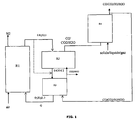
figure 1 est un schéma de principe de l'invention. Lafigure 1 illustre les flux des oxydes métalliques, et des charges solides, liquides et/ou gazeuses dans la configuration de base du procédé selon l'invention.Thefigure 1 is a block diagram of the invention. Thefigure 1 illustrates the flows of metal oxides, and solid, liquid and / or gaseous charges in the basic configuration of the process according to the invention. -
La
figure 2 illustre un mode de réalisation de l'invention concernant la production de gaz de synthèse sous pression.Thefigure 2 illustrates an embodiment of the invention concerning the production of synthesis gas under pressure. -
Les
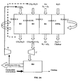
figures 3a et3b illustrent un mode de réalisation de l'invention dans lequel le procédé est mis en oeuvre en réacteur rotatif.Thefigures 3a and3b illustrate an embodiment of the invention in which the process is carried out in a rotary reactor.
Dans la description qui suit, on appelle "solide porteur d'oxygène" tout oxyde métallique pour lequel le degré d'oxydation du métal peut varier, en fonction de sa teneur en oxygène. Cette variation peut être exploitée pour transporter l'oxygène entre deux milieux réactifs. Dans un milieu oxydant riche en oxygène O2, on maximise le degré d'oxydation du métal, c'est-à-dire que l'on maximise la teneur en oxygène du solide. Dans un milieu pauvre en oxygène O2, le solide précédemment oxydé va relarguer spontanément une partie de son oxygène et voir son état d'oxydation diminuer par rapport à son degré d'oxydation lorsqu'il était complètement oxydé.In the following description, the term "oxygen carrier solid" any metal oxide for which the degree of oxidation of the metal can vary, depending on its oxygen content. This variation can be exploited to transport oxygen between two reactive media. In an oxidizing medium rich in oxygen O 2 , the degree of oxidation of the metal is maximized, that is to say that the oxygen content of the solid is maximized. In a medium low in oxygen O 2 , the previously oxidized solid will spontaneously release some of its oxygen and see its oxidation state decrease with respect to its oxidation state when it was completely oxidized.
On définit également un "solide porteur d'oxygène" par sa capacité de transfert d'oxygène réversible, c'est-à-dire la quantité d'oxygène que ce porteur peut échanger avec le milieu réactionnel entre son état le plus oxydé et le moins oxydé, et ce de façon réversible.An "oxygen carrier solid" is also defined by its reversible oxygen transfer capacity, that is to say the amount of oxygen that this carrier can exchange. with the reaction medium between its most oxidized and the least oxidized state, and this reversibly.
On définit X comme la fraction de la capacité totale de transfert d'oxygène restante dans l'oxyde.X is defined as the fraction of the total oxygen transfer capacity remaining in the oxide.
On définit enfin ΔX comme une fraction de la capacité de transfert d'oxygène totale.Finally, ΔX is defined as a fraction of the total oxygen transfer capacity.
Le fonctionnement du procédé selon l'invention se fait dans quatre zones réactives ou zones réactionnelles, qui peuvent être composées de réacteurs communs ou séparés et qui se distinguent par les réactions qui s'y produisent. Par esprit de simplification, dans les exemples suivants, chaque zone réactive ou zone réactionnelle sera associée à un réacteur. On les définit comme suit :
- réacteur de production d'oxygène (zone réactionnelle R2) : le solide porteur d'oxygène (oxyde métallique dans son état d'oxydation maximal) est exposé à une pression d'oxygène maintenue basse par le balayage d'un gaz vecteur ou au moyen d'une dépression. Cela a pour effet de faire sortir une partie de l'oxygène contenu dans le solide.
- réacteur de gazéification (zone réactionnelle R4) : l'oxygène extrait du solide est comprimé et amené au moyen du gaz vecteur au contact de la charge liquide ou solide à haute température de façon à la gazéifier. C'est ici qu'est produit le gaz de synthèse, (avantageusement) sous pression. Une partie du gaz produit peut être envoyée hors du procédé pour valorisation éventuelle, la partie restante (qui peut être la totalité) est utilisée au sein du procédé, d'une part pour apporter la chaleur nécessaire au fonctionnement et d'autre part pour éventuellement produire de la chaleur qui pourra être valorisée.
- réacteur de réduction (dit également "réacteur fuel", zone réactionnelle R3) : le gaz de synthèse produit est tout d'abord détendu (source possible d'énergie) puis amené au contact du solide porteur d'oxygène. En passant sous une forme plus réduite, le porteur d'oxygène libère de l'oxygène qui sera utilisé pour oxyder le gaz de synthèse. Cette réaction est globalement exothermique et constitue une source de chaleur du procédé.
- réacteur d'oxydation (dit également "réacteur air", zone réactionnelle R1) : le solide porteur d'oxygène, qui a été au moins en partie réduit pour fournir de l'oxygène au système, est réoxydé au contact de l'air dans ce réacteur sous sa forme la plus oxydée. Cette étape est exothermique et constitue l'autre source de chaleur du procédé.
- oxygen production reactor (reaction zone R2) : the oxygen-carrying solid (metal oxide in its maximum oxidation state) is exposed to a low oxygen pressure maintained by the scanning of a carrier gas or by means of of a depression. This has the effect of removing some of the oxygen contained in the solid.
- gasification reactor (reaction zone R4) : the oxygen extracted from the solid is compressed and brought by means of the carrier gas in contact with the liquid or solid charge at high temperature so as to gasify it. It is here that the synthesis gas (advantageously) is produced under pressure. Part of the product gas can be sent out of the process for possible recovery, the remaining part (which can be all) is used within the process, on the one hand to provide the necessary heat for operation and on the other hand for possible produce heat that can be valued.
- reduction reactor (also called "reactor fuel" reaction zone R3) : the synthesis gas produced is first relaxed (possible source of energy) and then brought into contact with the oxygen-carrying solid. By passing in a smaller form, the oxygen carrier releases oxygen which will be used to oxidize the synthesis gas. This reaction is generally exothermic and constitutes a heat source of the process.
- oxidation reactor (also called "air reactor", reaction zone R1): the oxygen-carrying solid, which has been at least partially reduced to supply oxygen to the system, is reoxidized in contact with the air in this reactor in its most oxidized form. This step is exothermic and is the other heat source of the process.
-
Le concept de base (
Figure 1 ) du procédé selon l'invention repose sur une configuration qui comprend :- 1. un réacteur "air" (zone réactionnelle R1) où se déroule la réaction d'oxydation des oxydes métalliques après réduction ;
- 2. un réacteur de "production d'oxygène" (zone réactionnelle R2) où le solide porteur d'oxygène relargue spontanément une partie de son oxygène dans un gaz vecteur composé des effluents de réduction, pauvres en oxygène. L'oxygène produit est ainsi transporté par le gaz vecteur vers le réacteur de gazéification ;
- 3. un réacteur de "gazéification" (zone réactionnelle R4) des charges solides et/ou liquides pour produire un gaz de synthèse au moyen d'un gaz oxydant enrichi en oxygène issu de R2 ;
- 4. un réacteur de "réduction" (zone réactionnelle R3) où se déroule la réaction de combustion de la charge gazéifiée en présence de l'oxygène présent dans les oxydes métalliques ;
- 5. des organes de séparations particules - gaz (cyclone) ;
- 6. des organes d'étanchéité et de liaison entre les réacteurs (siphon).
Figure 1 of the process according to the invention is based on a configuration which comprises:- 1. an "air" reactor (reaction zone R1) where the oxidation reaction of the metal oxides takes place after reduction;
- 2. an "oxygen production" reactor (reaction zone R2) in which the oxygen-carrying solid spontaneously releases part of its oxygen in a carrier gas composed of the oxygen-reducing reduction effluents. The oxygen produced is thus transported by the carrier gas to the gasification reactor;
- 3. a "gasification" reactor (reaction zone R4) of the solid and / or liquid charges to produce a synthesis gas by means of an oxygen-enriched oxidizing gas from R2;
- 4. a "reduction" reactor (reaction zone R3) in which the combustion reaction of the gasified feedstock takes place in the presence of the oxygen present in the metal oxides;
- 5. Particle-gas separation devices (cyclone);
- 6. Sealing and connecting elements between the reactors (siphon).
Dans le procédé selon l'invention, la fraction de capacité de transfert des oxydes métalliques est généralement fonction de la zone réactionnelle. Avantageusement :
- la fraction de capacité de transfert restante X est comprise entre 0,8
et 1, préférentiellement entre 0,95et 1 ce qui correspond à l'état le plus oxydé, en sortie de zone réactionnelle R1 ; - la fraction de capacité de transfert d'oxygène totale ΔX est comprise entre 0,01
et 1, préférentiellement entre 0.05 et 0.5, ce qui correspond à la quantité d'oxygène relargué spontanément par le matériau, dans la zone de production d'oxygène R2 ; - la fraction de capacité de transfert restante X est comprise entre 0 et 0,3, préférentiellement entre 0
et 0,1, ce qui correspond à l'état le plus réduit, en sortie de zone réactionnelle R3.
- the fraction of remaining transfer capacity X is between 0.8 and 1, preferably between 0.95 and 1, which corresponds to the most oxidized state, at the outlet of reaction zone R1;
- the fraction of total oxygen transfer capacity ΔX is between 0.01 and 1, preferably between 0.05 and 0.5, which corresponds to the quantity of oxygen released spontaneously by the material, in the oxygen production zone R2. ;
- the fraction of remaining transfer capacity X is between 0 and 0.3, preferably between 0 and 0.1, which corresponds to the smallest state, at the outlet of reaction zone R3.
Dans la description des figures qui suit, on désignera par simplification par le terme "réacteur" une zone réactionnelle comprenant un ou plusieurs réacteurs dans lesquels se déroulent des réactions de même nature.In the following description of the figures, the term "reactor" will be used simply to denote a reaction zone comprising one or more reactors in which reactions of the same type take place.
Un débit d'oxydes métalliques circule du réacteur air (réacteur d'oxydation R1) dans son état le plus oxydé (0.8≤X≤1 et préférentiellement 0.95≤X≤1) vers le réacteur de production d'oxygène (R2) où le matériau relargue spontanément son oxygène (0.01≤ΔX≤1, préférentiellement 0.05≤ΔX≤0.5) dans un flux de gaz vecteur composé (au moins en partie) d'effluent de la réduction (R3) (CO2+H2O) pauvre en oxygène. Cet effluent gazeux est transporté vers le réacteur de gazéification R4 où il est mis en contact d'un combustible pour produire un gaz de synthèse. Celui-ci est envoyé tout ou partie dans le réacteur de réduction (R3), le reste pouvant être valorisé dans des applications telles que Fischer-Tropsch ou pile à combustible. Dans le réacteur de réduction (R3), le gaz de synthèse réagit au contact du porteur d'oxygène. Cette réaction est exothermique et produit un gaz quasiment exclusivement composé de dioxyde de carbone et de vapeur d'eau. A l'issue de cette réaction, le solide porteur d'oxygène est dans sa forme la plus réduite (0≤x≤0.3, préférentiellement 0≤x≤0.1) et est renvoyé vers le réacteur d'oxydation (R1). Il y est réoxydé dans son état d'oxydation maximal (0.8≤x≤1, préférentiellement 0.95≤x≤1) au cours d'une réaction exothermique avec l'oxygène de l'air. Le procédé sera complété aussi par des unités de traitement de soufre sous forme H2S et/ou SO2 si le combustible contient du soufre.A flow of metal oxides flows from the air reactor (oxidation reactor R1) in its most oxidized state (0.8≤X≤1 and preferably 0.95≤X≤1) to the oxygen production reactor (R2) where the material spontaneously releases its oxygen (0.01
Un avantage du procédé selon l'invention est de pouvoir produire du gaz de synthèse sous pression, dans un mode de réalisation illustré par la
Les principes exposés au travers des
Dans ce mode de réalisation particulier, le transport du solide entre les différentes zones réactionnelles est opéré au moyen d'un réacteur tournant; il s'agit d'un dispositif le plus souvent constitué d'une matrice poreuse cylindrique autorisant le passage des gaz le long de son axe de rotation. La phase active, c'est-à-dire le porteur d'oxygène, est immobilisé sur cette matrice. La rotation du réacteur cylindrique se fait en face des arrivées des réactifs et des évents. La portion de cylindre comprise entre un couple entrée de réactifs/évent constitue une zone réactionnelle.In this particular embodiment, the transport of the solid between the different reaction zones is carried out by means of a rotating reactor; it is a device usually consisting of a porous cylindrical matrix allowing the passage of gases along its axis of rotation. The active phase, that is to say the oxygen carrier, is immobilized on this matrix. The rotation of the cylindrical reactor is opposite the arrivals of the reactants and the vents. The portion of the cylinder comprised between a reactive / vented inlet pair constitutes a reaction zone.
Par analogie avec les dispositifs décrits précédemment on définit quatre zones réactionnelles :
- R1 : zone réactionnelle alimentée en air "N2+O2", la rotation du cylindre fait que la section de cylindre qui entre dans la zone réactionnelle supporte le solide porteur d'oxygène partiellement réduit (0≤X≤0.3) et que la section de cylindre qui sort de la zone réactionnelle supporte le solide porteur d'oxygène dans son état le plus oxydé (0.8≤X≤1, préférentiellement 0.95≤X≤1). La sortie des gaz de la zone réactionnelle R1 se fait par un évent, conduisant l'air appauvri en oxygène "N2" à l'extérieur de l'unité. La zone réactionnelle R1 correspond à ce qui a été défini précédemment comme le réacteur air.
- R2 : zone réactionnelle alimentée en CO2 et en H2O qui suit la zone R1 dans la séquence de rotation du cylindre. La portion de cylindre qui entre dans cette zone porte ainsi le porteur d'oxygène dans son état le plus oxydé (0.8≤X≤1, préférentiellement 0.95≤X≤1). Cette zone réactionnelle correspond à ce qui a été défini précédemment comme le réacteur de production d'oxygène, les gaz qui sortent de cette zone par l'évent sont constitués de CO2, d'H2O, mais aussi d'O2 destinés à la gazéification de la charge. Cet effluent est compressé. La portion de cylindre qui sort de la zone réactionnelle porte le solide partiellement réduit (0.01≤ΔX≤0.99 et préférentiellement 0.05≤ΔX≤0.50).
- R4 : cette zone n'est pas comprise dans le cycle réactionnel du réacteur tournant. Il s'agit d'un réacteur de gazéification d'hydrocarbure, externe au réacteur tournant, alimenté en gaz oxydants sous pression par les effluents de la zone réactionnelle R3 et alimenté en charge hydrocarbure solide ou liquide. L'effluent gazeux est constitué majoritairement et de façon préférentielle de gaz de synthèse H2 + CO sous pression. Selon le mode de fonctionnement choisi, tout ou partie du gaz de synthèse est envoyé en zone de combustion R3 selon que l'on veut respectivement favoriser la production de chaleur ou de gaz de synthèse. Le gaz de synthèse étant sous pression, il est détendu dans une turbine avant d'être envoyé vers la zone réactionnelle R3.
- R3 : zone réactionnelle alimentée en gaz de synthèse H2 + CO détendu par le gazéifieur externe (zone réactionnelle R4). La zone réactionnelle R3 suit la zone réactionnelle R2 dans la séquence de rotation du cylindre. Cette zone réactionnelle correspond à ce qui a été défini précédemment comme le "réacteur fuel". La portion de cylindre qui entre dans la zone R3 porte le solide dans un état oxydé au degré d'oxydation correspondant à la sortie de la zone "réacteur de production d'oxygène" (0.01≤X≤1 et préférentiellement 0.50≤X≤0.95). Le porteur est réduit au contact du gaz de synthèse. L'effluent gazeux qui sort de la zone réactionnelle R3 est quasi exclusivement constitué de CO2 et H2O. Le solide porteur d'oxygène qui sort de la zone réactionnelle R3 est dans son état le plus réduit de tout le cycle réactionnel (0≤X≤0.3 préférentiellement 0≤X≤0.1).
- UTIL : cette zone réactionnelle correspond à l'utilisation de la chaleur. Les réactions qui ont lieu sur le cylindre sont globalement exothermiques. Dans la zone UTIL on va surchauffer de la vapeur au contact du solide pour équilibrer le bilan thermique du cycle. C'est ce qui permet de fournir de la chaleur à l'utilisateur. Au cours de cette étape, une réoxydation partielle est possible (0≤X≤0.9 et préférentiellement 0≤X≤0.1).
- R1: reaction zone supplied with air "N 2 + O 2 ", the rotation of the cylinder causes the cylinder section which enters the reaction zone to support the partially reduced oxygen carrier solid (0≤X≤0.3) and the section of the cylinder that leaves the reaction zone supports the oxygen-carrying solid in its most oxidized state (0.8≤X≤1, preferably 0.95≤X≤1). The exit of the gases from the reaction zone R1 is carried out by a vent, bringing oxygen-depleted air "N 2 " to the outside of the unit. The reaction zone R1 corresponds to what has been defined previously as the air reactor.
- R2: reaction zone supplied with CO 2 and H 2 O which follows the
zone R 1 in the rotation sequence of the cylinder. The portion of the cylinder that enters this zone thus carries the oxygen carrier in its most oxidized state (0.8≤X≤1, preferentially 0.95≤X≤1). This reaction zone corresponds to what has been defined previously as the oxygen production reactor, the gases leaving this zone through the vent consist of CO 2 , H 2 O, but also O 2 intended the gasification of the charge. This effluent is compressed. The portion of the cylinder that leaves the reaction zone carries the partially reduced solid (0.01 Δ Δ x 0 0.99 and preferably 0.05 Δ X ≤ 0.0). - R4: this zone is not included in the reaction cycle of the rotating reactor. It is a hydrocarbon gasification reactor, external to the rotating reactor, fed with oxidizing gases under pressure by the effluents of the reaction zone R3 and fed with solid or liquid hydrocarbon feedstock. The gaseous effluent consists mainly and preferably of H 2 + CO synthesis gas under pressure. Depending on the mode of operation chosen, all or part of the synthesis gas is sent to the combustion zone R3 according to whether it is desired respectively to promote the production of heat or synthesis gas. The synthesis gas being under pressure, it is expanded in a turbine before being sent to the reaction zone R3.
- R3: reaction zone supplied with synthesis gas H 2 + CO expanded by the external gasifier (reaction zone R4). The reaction zone R3 follows the reaction zone R2 in the rotation sequence of the cylinder. This reaction zone corresponds to what has been defined previously as the "fuel reactor". The portion of the cylinder that enters the zone R3 carries the solid in an oxidized state at the oxidation state corresponding to the output of the zone "oxygen production reactor" (0.01≤X≤1 and preferably 0.50≤X≤0.95 ). The carrier is reduced in contact with the synthesis gas. The gaseous effluent leaving the reaction zone R3 consists almost exclusively of CO 2 and H 2 O. The oxygen-carrying solid leaving the reaction zone R 3 is in its most reduced state of the entire reaction cycle (0). ≤X≤0.3 preferably 0≤X≤0.1).
- UTIL: This reaction zone corresponds to the use of heat. The reactions taking place on the cylinder are generally exothermic. In the UTIL area, steam will be superheated in contact with the solid to balance the thermal balance of the cycle. This is to provide heat to the user. During this step, a partial reoxidation is possible (0≤X≤0.9 and preferably 0≤X≤0.1).
Cette figure représente une proposition de répartition spatiale des zones réactives pour le système à réacteur tournant décrit précédemment. Chaque zone occupe ainsi une portion de cylindre contiguë à la suivante autour l'axe de rotation du cylindre.This figure represents a proposal for spatial distribution of the reactive zones for the rotating reactor system described above. Each zone thus occupies a portion of cylinder contiguous to the next around the axis of rotation of the cylinder.
Les oxydes métalliques utilisables dans le procédé selon l'invention peuvent être choisis parmi les oxydes des éléments de transition des colonnes IIIB à IIB (par exemple Fe, Ti, Ni, Cu, Mo, Mn, Co, V) de la classification périodique, seuls ou en mélange, associés ou non à un liant de type céramique leur conférant une résistance mécanique améliorée (les liants susceptibles d'être utilisés sont par exemple l'alumine, les aluminates de type spinelle, la silice, le dioxyde de titane, le kaolin, la cérine zircone, la bentonite ou des catalyseurs usagés.) et éventuellement une meilleure capacité de transfert d'oxygène (notamment pour les liants de type cérine-zircone). Sont utilisables également les oxydes de type perovskite, spinelle, olivine, hematite, ilmenite, pyrochlore. Il s'agit de familles d'oxydes simples ou mixtes dont la structure est bien déterminée.The metal oxides that can be used in the process according to the invention can be chosen from the oxides of the transition elements of columns IIIB to IIB (for example Fe, Ti, Ni, Cu, Mo, Mn, Co, V) of the periodic table. singly or in combination, with or without a ceramic-type binder, giving them improved mechanical strength (the binders that may be used are, for example, alumina, spinel aluminates, silica, titanium dioxide, kaolin, ceria zirconia, bentonite or used catalysts.) and possibly a better oxygen transfer capacity (especially for ceria-zirconia type binders). It is also possible to use perovskite, spinel, olivine, hematite, ilmenite and pyrochlore oxides. These are families of simple or mixed oxides whose structure is well determined.
Les oxydes métalliques peuvent être sous la forme de minerais naturels (comme l'ilménite, l'hématite par exemple) ou sous une forme synthétique optimisée pour obtenir une meilleure capacité de transfert d'oxygène.The metal oxides can be in the form of natural ores (such as ilmenite, hematite for example) or in synthetic form optimized for better oxygen transfer capacity.
De préférence, ces solides sont conditionnés sous la forme de poudre, de diamètre de Sauter compris préférentiellement entre 30 et 500 microns, et de masse volumique de grain comprise entre 1400 et 8000 kg/m3, préférentiellement entre 1400 et 5000 kg/m3.Preferably, these solids are packaged in the form of powder, Sauter diameter preferably between 30 and 500 microns, and grain density of between 1400 and 8000 kg / m3, preferably between 1400 and 5000 kg / m3.
On s'assure d'avoir un design adapté pour que les réactions dans les réacteurs "air" (R1), production d'oxygène (R2), fuel (R3) et gazéification (R4) se déroulent à une température comprise entre 700 °C et 1200 °C.It is ensured to have a design adapted so that the reactions in the "air" (R1), oxygen production (R2), fuel (R3) and gasification (R4) reactors take place at a temperature of between 700 ° C. C and 1200 ° C.
Le temps de résidence de l'oxyde métallique dans le réacteur air (R1) dépend de l'état d'oxydation et/ou réduction de ces oxydes et peut être estimé entre 1 et 20 minutes.The residence time of the metal oxide in the air reactor (R1) depends on the oxidation state and / or reduction of these oxides and can be estimated between 1 and 20 minutes.
Le temps de résidence de l'oxyde métallique dans le réacteur de production d'oxygène (R2) dépend de la nature du solide porteur d'oxygène et peut être estimé entre 1 seconde et 360 secondes.The residence time of the metal oxide in the oxygen generating reactor (R2) depends on the nature of the oxygen-carrying solid and can be estimated between 1 second and 360 seconds.
Le temps de résidence de l'oxyde métallique dans le réacteur fuel (R3) dépend de la nature du combustible et peut être estimé entre 1 et 15 minutes.The residence time of the metal oxide in the fuel reactor (R3) depends on the nature of the fuel and can be estimated between 1 and 15 minutes.
Le temps de résidence de l'oxyde métallique dans le réacteur de gazéification (R4) dépend de la nature du combustible à gazéifier et peut être estimé entre 1 et 20 minutes.The residence time of the metal oxide in the gasification reactor (R4) depends on the nature of the fuel to be gasified and can be estimated between 1 and 20 minutes.
Dans le cas du réacteur tournant, le temps de résidence de l'oxyde dans la partie UTIL de récupération de chaleur dépend de la quantité de chaleur à évacuer et de la nature du flux utilisé pour récupérer la chaleur produite. Le temps de résidence dans la partie UTIL peut être estimé entre 1 seconde et 600 secondes.In the case of the rotating reactor, the residence time of the oxide in the UTI portion of heat recovery depends on the amount of heat to be removed and the nature of the flow used to recover the heat produced. The residence time in the UTIL part can be estimated between 1 second and 600 seconds.
Les avantages de l'invention énumérés ci-dessous sont décrits à titre non limitatif.
- 1. L'invention permet le couplage entre le procédé de combustion en boucle chimique "chemical looping combustion", le procédé de gazéification et la production d'oxygène.
- 2. L'invention permet d'injecter directement du charbon, du coke de pétrole ou des charges lourdes dans le réacteur de gazéification en contact avec l'oxygène fourni par le transporteur d'oxygène dans le réacteur de production d'oxygène. On désigne par charges lourdes des charges dont moins de 10% en masse a un point d'ébullition inférieur à 340°C.
- 3. L'invention permet de produire du gaz de synthèse sous pression dans le réacteur de gazéification par compression du gaz vecteur riche en oxygène de façon à économiser l'énergie, plus importante, qu'il faudrait pour gazéifier le gaz de synthèse (CO+H2) chaud en sortie d'unité.
- 4. L'invention permet d'appauvrir le gaz vecteur en eau par condensation pour en améliorer la compressibilité.
- 5. L'invention permet de récupérer la chaleur du gaz vecteur d'oxygène avant compression et l'énergie de détente du gaz de synthèse pour alimenter le compresseur du gaz vecteur d'oxygène.
- 6. L'invention permet l'utilisation de l'intégralité du gaz de synthèse, si nécessaire, pour produire de la chaleur au sein du procédé dans le réacteur de réduction.
- 7. L'invention permet la production de gaz de synthèse par le présent procédé en valorisant un maximum de gaz de synthèse en sortie du réacteur de gazéification et en recyclant le minimum nécessaire au bon fonctionnement du procédé.
- 8. L'invention permet de fournir l'énergie nécessaire pour la production de gaz de synthèse sous pression ainsi que la production de l'énergie et/ou de l'électricité dans le cas de la boucle chimique de combustion couplée à un réacteur de production d'oxygène.
- 9. Dans le procédé selon l'invention, la charge, de préférence une charge lourde, est gazéifiée avec un mélange enrichi à l'oxygène, ce qui rend le processus de gazéification exothermique (zone réactionnelle R4). De plus la combustion de gaz de synthèse dans le réacteur fuel est exothermique et conduit à augmenter l'efficacité énergétique du procédé en évitant d'avoir des étapes endothermiques qui nécessiteraient un apport externe d'énergie.
- 1. The invention allows coupling between the chemical looping combustion process, the gasification process and the production of oxygen.
- 2. The invention makes it possible to directly inject coal, petroleum coke or heavy charges into the gasification reactor in contact with the oxygen supplied by the oxygen carrier in the oxygen production reactor. Heavy loads are charges of which less than 10% by mass has a boiling point below 340 ° C.
- 3. The invention makes it possible to produce pressurized synthesis gas in the gasification reactor by compression of the oxygen-rich carrier gas so as to save the higher energy required to gasify the synthesis gas (CO 2). + H2) hot at the end of the unit.
- 4. The invention makes it possible to deplete the carrier gas in water by condensation to improve compressibility.
- 5. The invention makes it possible to recover the heat of the oxygen carrier gas before compression and the expansion energy of the synthesis gas for supplying the compressor with the oxygen carrier gas.
- 6. The invention allows the use of all of the synthesis gas, if necessary, to produce heat within the process in the reduction reactor.
- 7. The invention allows the production of synthesis gas by the present method by upgrading a maximum of synthesis gas output of the gasification reactor and recycling the minimum necessary for the proper operation of the process.
- 8. The invention makes it possible to supply the energy necessary for the production of synthesis gas under pressure as well as the production of energy and / or electricity in the case of the chemical combustion loop coupled to a reactor of oxygen production.
- In the process according to the invention, the filler, preferably a heavy filler, is gasified with an oxygen-enriched mixture, which makes the exothermic gasification process (reaction zone R4). In addition, the combustion of synthesis gas in the fuel reactor is exothermic and leads to increase the energy efficiency of the process by avoiding having endothermic stages that would require an external supply of energy.
Les exemples ci-après montrent l'avantage par rapport aux autres technologies du procédé selon la présente invention, qui permet de produire du gaz de synthèse et/ou de la chaleur au moyen d'un dispositif incluant une boucle chimique avec un solide porteur d'oxygène et un gazéifieur de charge liquide ou solide sans qu'il y ait contact entre le solide porteur d'oxygène et la charge liquide ou solide, pour éviter le recours à des organes spécifiques de séparation solide-solide.The following examples show the advantage over other technologies of the process according to the present invention, which makes it possible to produce synthesis gas and / or heat by means of a device including a chemical loop with a solid which carries oxygen and a liquid or solid charge gasifier without contact between the solid carrier of oxygen and the liquid or solid charge, to avoid the use of specific solid-solid separation organs.
Dans les exemples, deux modes de réalisation possibles de l'invention sont illustrés : dans le premier on cherche à maximiser la production de gaz de synthèse, dans le second on cherche à valoriser la charge sous la forme de production de chaleur. Dans chaque cas, les bilans matière et énergie sont présentés. Un cas général sera tout d'abord exposé pour expliciter les données utilisées dans ces exemples.In the examples, two possible embodiments of the invention are illustrated: in the first one seeks to maximize the production of synthesis gas, in the second it seeks to enhance the load in the form of heat production. In each case, the material and energy balances are presented. A general case will first be explained to explain the data used in these examples.
Les conditions opératoires considérées à chaque étape sont les suivantes :The operating conditions considered at each stage are the following:
- 1) la réaction de gazéification est opérée de façon autotherme à une température qui est fonction de l'exothermicité de la réaction, donc de la quantité d'oxygène introduite;1) the gasification reaction is operated autothermally at a temperature which is a function of the exothermicity of the reaction, therefore the amount of oxygen introduced;
- 2) les paramètres de fluidisation ne sont pas pris en compte;2) the fluidization parameters are not taken into account;
- 3) les réactifs sont la charge solide ou liquide;3) the reagents are the solid or liquid charge;
- 4) la réaction est endothermique en absence d'oxygène.4) the reaction is endothermic in the absence of oxygen.
- 1) la réaction de réduction est complète. Les produits de la réaction sont du CO2 et de H2O;1) The reduction reaction is complete. The products of the reaction are CO 2 and H 2 O;
- 2) l'échange est idéal entre le transporteur d'oxygène et le combustible gazeux : il n'y a pas de limitation diffusionnelle, pas de formation de carbone, pas de perte de réactivité;2) the exchange is ideal between the oxygen carrier and the gaseous fuel: there is no diffusion limitation, no carbon formation, no loss of reactivity;
- 3) la réaction est exothermique.3) the reaction is exothermic.
- 1) la réaction d'oxydation est complète ;1) the oxidation reaction is complete;
- 2) l'échange est idéal entre le transporteur d'oxygène et l'air ;2) the exchange is ideal between the oxygen carrier and the air;
- 3) la réaction est exothermique.3) the reaction is exothermic.
- 1) l'avancement de la réaction est limité à 2% maximum ;1) the progress of the reaction is limited to 2% maximum;
- 2) la réaction est endothermique.2) the reaction is endothermic.
Le solide porteur d'oxygène choisi est un oxyde mixte fer - manganèse pour lequel on considère que l'on peut extraire jusqu'à deux pourcents en poids de l'oxygène qu'il contient dans sa forme la plus oxydée. La réaction réversible d'oxydation considérée est la suivante, pour T > 1000 K :
{MnO + 3.Fe2MnO4} + O2 --> 5.(Fe0,6Mn0,4)2O3 ΔHr = -85,76 kJ/mol(O2) à 1000 KThe oxygen-carrying solid chosen is a mixed iron-manganese oxide for which it is considered that up to two percent by weight of the oxygen it contains can be extracted in its most oxidized form. The reversible reaction of oxidation considered is the following, for T> 1000 K:
{MnO + 3.Fe 2 MnO 4 } + O 2 -> 5. (Fe 0.6 Mn 0.4 ) 2 O 3 ΔH r = -85.76 kJ / mol (O 2 ) at 1000 K
Les caractéristiques des formes oxydées et réduites sont les suivantes : forme oxydée : (Fe0,6Mn0,4)2O3
Cp = 1,018 kJ/kg/K (valeur calculée par la méthode des contributions de groupe - 1
M = 158,96 g/molThe characteristics of the oxidized and reduced forms are as follows: oxidized form: (Fe 0.6 Mn 0.4 ) 2 O 3
Cp = 1.018 kJ / kg / K (value calculated by the group contribution method - 1
M = 158.96 g / mol
Les caractéristiques des formes oxydées et réduites sont les suivantes :
forme oxydée : {MnO + 3.Fe2MnO4}
Cp = 0,905 kJ/kg/K (valeur calculée par la méthode des contributions de groupe -1
M = 762.81 g/molThe characteristics of the oxidized and reduced forms are as follows:
oxidized form: {MnO + 3.Fe 2 MnO 4 }
Cp = 0.905 kJ / kg / K (value calculated by the method of group contributions -1
M = 762.81 g / mol
Pour les réactions de réduction, cela correspond à la combustion des différents composés du gaz de synthèse sur le solide :
- Dihydrogène :
- H2 + 5/2(Fe0,6Mn0,4)2O3 --> 1/2{MnO + 3.Fe2MnO4} +H2O ΔHr = -206,48 kJ/mol(H2) à 1000 K
- Dihydrogen:
- H 2 + 5/2 (Fe 0.6 Mn 0.4 ) 2 O 3 -> 1/2 {MnO + 3.Fe 2 MnO 4 } + H 2 O ΔH r = -206.48 kJ / mol ( H 2 ) to 1000 K
Monoxyde de carbone :
CO + 5/2(Fe0,6Mn0,4)2O3 --> 1/2{MnO + 3.Fe2MnO4} +CO2 ΔHr = -238,55 kJ/mol(CO) à 1000 KCarbon monoxide :
CO + 5/2 (Fe 0.6 Mn 0.4 ) 2 O 3 -> 1/2 {MnO + 3.Fe 2 MnO 4 } + CO 2 ΔH r = -238.55 kJ / mol (CO) at 1000 K
Méthane :
CH4 + 10.(Fe0,6Mn0,4)2O3 --> 2{MnO + 3.Fe2MnO4} +2.H2O + CO2 ΔHr = -630,38 kJ/mol(CH4) à 1000 KMethane:
CH 4 + 10. (Fe 0.6 Mn 0.4 ) 2 O 3 -> 2 {MnO + 3.Fe 2 MnO 4 } + 2.H 2 O + CO 2 ΔH r = -630.38 kJ / mol (CH 4 ) to 1000 K
La réaction de gazéification de la charge est modélisée par une minimisation de l'énergie de Gibbs dont l'enthalpie est calculée en fonction des énergies de formation des différentes espèces présentes.The gasification reaction of the charge is modeled by a minimization of the Gibbs energy whose enthalpy is calculated as a function of the formation energies of the various species present.
La charge choisie dans cet exemple est une charge liquide modèle C18H30 qui représente l'utilisation d'un fioul moyen.The charge selected in this example is a model C 18 H 30 liquid charge which represents the use of a medium fuel oil.
Le débit de charge choisi va déterminer la quantité de solide à mettre en circulation dans la boucle en fonction des besoins en oxygène des opérations de gazéification et de combustion.The selected charge rate will determine the amount of solids to be circulated in the loop depending on the oxygen requirements of the gasification and combustion operations.
La présente invention permet de moduler la production entre la maximisation de l'énergie thermique produite par le procédé ou la maximisation de la quantité de gaz de synthèse (Syngaz) sortant du procédé par rapport à la quantité de charge hydrocarbonée introduite.The present invention makes it possible to modulate the production between the maximization of the thermal energy produced by the process or the maximization of the amount of synthesis gas (Syngaz) leaving the process with respect to the amount of hydrocarbon feedstock introduced.
Dans le présent exemple on cherche à maximiser la quantité de gaz de synthèse produite.In the present example, it is sought to maximize the amount of synthesis gas produced.
Le solide porteur d'oxygène est balayé avec un gaz pour maintenir basse la pression partielle d'oxygène. Ce gaz sert aussi de gaz vecteur pour transporter l'oxygène dans le gazéifieur. On utilise ici les gaz chauds issus de la combustion du gaz de synthèse sur le solide, qui sont recyclés aux trois quarts. Ce gaz est composé d'eau et de dioxyde de carbone et arrive à une température de 902 °C et un débit de 11,4 kmol/h. La réaction de production d'oxygène est endothermique et consomme 444 kW sous forme de chaleur.The oxygen-carrying solid is flushed with a gas to keep the oxygen partial pressure low. This gas also serves as a carrier gas for transporting oxygen in the gasifier. Hot gases from the combustion of synthesis gas on the solid are used here, which are recycled three-quarters. This gas is composed of water and carbon dioxide and reaches a temperature of 902 ° C and a flow rate of 11.4 kmol / h. The oxygen production reaction is endothermic and consumes 444 kW as heat.
La température de sortie des gaz est aussi de 897 °C.The exit temperature of the gases is also 897 ° C.
Dans ce réacteur, de multiples réactions ont lieu, on considère les réactions suivantes :
C+H 2 O↔CO+H 2 , ΔHr 298 K =131kJ.mol -1
C+CO 2↔2CO, ΔHr 298 K =173kJ.mol -1

C+O 2↔CO 2, ΔHr 298 K =-395kJ.mol -1


CO+H 2 O↔CO 2 +H 2, ΔHr 298 K =-41kJ.mol -1
C+2.H 2↔CH 2, ΔHr 298K =-74.87kJ.mol -1
4.CnHm ↔m.CH 4+(4n-m).C, ΔHr 298K <0
In this reactor, multiple reactions take place, consider the following reactions:
C + H 2 O + CO + H 2 , ΔHr 298 K = 131 kJ.mol -1
C + CO 2 CO ↔2, Δ Hr 298 K = 173 kJ mol -1
C + O 2 ↔ CO 2, ΔHr 298 K = -395 kJ mol -1
CO + H 2 O ↔ CO 2 + H 2, Δ Hr 298 K = -41 kJ mol -1
C +2. H 2 ↔ CH 2, Δ Hr 298 K = -74.87 kJ mol -1
4.C n H m ↔ m.CH 4 + (4 n - m ). C , ΔHr 298 K <0
Dans notre cas, on se place à l'équilibre et la détermination de la composition du gaz de synthèse se fait par minimisation de l'énergie de Gibbs.In our case, the equilibrium is set and the composition of the synthesis gas is determined by minimizing the Gibbs energy.
Dans le procédé selon la présente invention, le gaz vecteur d'oxygène est comprimé avant gazéification de façon à gazéifier sous pression et obtenir un gaz de synthèse sous pression. Ici la dépense d'énergie pour comprimer le gaz vecteur d'oxygène est estimée à 166 kWe. La compression de ce gaz nécessite de le refroidir, ce qui est fait par de l'eau pour produire de la vapeur dans un échangeur type tube - calandre.In the process according to the present invention, the oxygen carrier gas is compressed before gasification so as to gasify under pressure and obtain a synthesis gas under pressure. Here the energy expenditure for compressing the oxygen carrier gas is estimated at 166 kWe. The compression of this gas requires cooling, which is done by water to produce steam in a tube-shell heat exchanger.
La gazéification s'opère à 40 bars, les réactifs entrent à 905 °C et sortent à 1058 °C du fait de l'exothermicité de la gazéification en présence d'oxygène.The gasification is carried out at 40 bars, the reactants enter at 905 ° C. and leave at 1058 ° C. because of the exothermicity of the gasification in the presence of oxygen.
La réaction produit ainsi un gaz de synthèse dont 75 % sont extraits du procédé pour être valorisés, soit 980 kg/h de gaz de synthèse à 40 bars et 1058 °C.The reaction thus produces a synthesis gas of which 75% is extracted from the process to be recovered, ie 980 kg / h of synthesis gas at 40 bar and 1058 ° C.
Dans ce réacteur, le gaz de synthèse est oxydé au contact du solide porteur d'oxygène selon les réactions et les enthalpies de réaction citées précédemment.
L'énergie récupérée au niveau de cette combustion est de 0,87 MWth.The energy recovered at the level of this combustion is 0.87 MWth.
75 % des fumées sont recyclées, le reste est extrait de l'unité. Il s'agit d'un flux composé uniquement d'eau et de dioxyde de carbone destiné à être récupéré, transporté et stocké. L'énergie potentiellement récupérable sur ce flux est estimée à 39 kWth.75% of the fumes are recycled, the rest is extracted from the unit. It is a stream composed solely of water and carbon dioxide to be recovered, transported and stored. The potentially recoverable energy on this flow is estimated at 39 kWth.
Les fluides et solides sortent du réacteur de réduction à une température de 902 °C contre une température de 897 °C en entrée.The fluids and solids leave the reduction reactor at a temperature of 902 ° C against a temperature of 897 ° C inlet.
La chaleur produite par le procédé et transportée par le solide est valorisable en sortie de réacteur de réduction. Pour que le bilan thermique soit équilibré, on ne valorise pas de chaleur à ce niveau.The heat produced by the process and transported by the solid is recoverable at the outlet of the reduction reactor. For the thermal balance is balanced, it does not value heat at this level.
En sortie du réacteur de réduction, le solide est dans son état le plus réduit. Dans le réacteur d'oxydation, il est réoxydé dans sa forme la plus oxydée au contact d'un flux d'air.
L'énergie fournie dans ce réacteur par la réaction d'oxydation et pour amener les composés à 1100 °C est de 935 kW. Une partie de cette énergie est valorisable en récupérant la chaleur sur le flux d'air appauvri, soit 0,17 MWth dans la boucle vapeur.The energy supplied to this reactor by the oxidation reaction and to bring the compounds to 1100 ° C is 935 kW. Part of this energy is recoverable by recovering the heat on the depleted airflow, ie 0.17 MWth in the steam loop.
Au final ce procédé produit :In the end this process produces:
0,74 T/h de gaz de synthèse à 40 bar et 1058 °C et 5,13 MWth pour 0,37 T/h de charge C18H30.0.74 T / h of syngas at 40 bar and 1058 ° C and 5.13 MWth at 0.37 T / h of C18H30 feedstock.
Le gaz de synthèse a la composition suivante :
L'excédent de chaleur du procédé, soit 331kWth, est destiné au réchauffage de la charge qui nécessite 277 kWth.The excess heat of the process, ie 331kWth, is intended for reheating the load which requires 277 kWth.
La présente invention permet de moduler la production entre :
- la maximisation de l'énergie thermique produite par le procédé;
- ou la maximisation de la quantité de gaz de synthèse (Syngaz) sortant du procédé par rapport à la quantité de charge hydrocarbonée introduite.
- maximizing the thermal energy produced by the process;
- or maximizing the amount of synthesis gas (Syngaz) leaving the process relative to the amount of hydrocarbon feedstock introduced.
Dans le présent exemple on cherche à maximiser la quantité de chaleur produite par le procédé.In the present example, it is sought to maximize the amount of heat produced by the process.
Le solide porteur d'oxygène est balayé avec un gaz pour maintenir basse la pression partielle d'oxygène. Ce gaz sert aussi de gaz vecteur pour transporter l'oxygène dans le gazéifieur. On utilise ici les gaz chauds issus de la combustion du gaz de synthèse sur le solide qui sont recyclés aux trois quarts. Ce gaz est composé d'eau et de dioxyde de carbone et arrive à une température de 934 °C et un débit de 169 kmol/h. La réaction de production d'oxygène est endothermique et consomme 444 kW sous forme de chaleur.The oxygen-carrying solid is flushed with a gas to keep the oxygen partial pressure low. This gas also serves as a carrier gas for transporting oxygen in the gasifier. Hot gases from the combustion of synthesis gas on the solid are used here, which are recycled three-quarters. This gas is composed of water and carbon dioxide and reaches a temperature of 934 ° C and a flow rate of 169 kmol / h. The oxygen production reaction is endothermic and consumes 444 kW as heat.
La température de sortie des gaz est aussi de 897 °C.The exit temperature of the gases is also 897 ° C.
Dans ce réacteur, de multiples réactions ont lieu, on considère les réactions suivantes :
C+H 2 O ↔ CO+H 2 , ΔHr 298 K =131kJ.mol -1
C+CO 2 ↔ 2CO, ΔHr 298 K =173kJ.mol -1

C+O 2 ↔ CO 2 , ΔHr 298 K =-395kJ.mol -1

![]()
CO+H 2 O ↔ CO 2 +H 2 , ΔHr 298 K =-41kJ.mol-1
C+2.H 2 ↔ CH 2 , ΔHr 298 K =-74.87kJ.mol -1
4.CnHm ↔ m.CH 4 +(4n-m).C, ΔHr 298K <0
In this reactor, multiple reactions take place, consider the following reactions:
C + H 2 O + CO + H 2 , ΔHr 298 K = 131 kJ.mol -1
C + CO 2 ↔ 2 CO, ΔHr 298 K = 173 kJ.mol -1
C + O 2 ↔ CO 2, ΔHr 298 K = -395 kJ mol -1
![]()
CO + H 2 O ↔CO 2 + H 2 , ΔHr 298 K = -41kJ.mo l -1
C +2 .H 2 ↔ CH 2 , ΔHr 298 K = -74.87kJ.mol -1
4.C n H m ↔ m.CH 4 + (4 n-m ). C, ΔHr 298 K <0
Dans notre cas, on se place à l'équilibre et la détermination de la composition du gaz de synthèse se fait par minimisation de l'énergie de Gibbs.In our case, the equilibrium is set and the composition of the synthesis gas is determined by minimizing the Gibbs energy.
Dans le procédé selon la présente invention, le gaz vecteur d'oxygène est comprimé avant gazéification de façon à gazéifier sous pression et obtenir un gaz de synthèse sous pression. Ici la dépense d'énergie pour comprimer le gaz vecteur d'oxygène est estimée à 1392 kWe. La compression de ce gaz nécessite de le refroidir, ce qui est fait par de l'eau pour produire de la vapeur dans un échangeur type tube - calandre soit 1,69 MWth.In the process according to the present invention, the oxygen carrier gas is compressed before gasification so as to gasify under pressure and obtain a synthesis gas under pressure. Here the energy expenditure for compressing the oxygen carrier gas is estimated at 1392 kWe. The compression of this gas requires cooling, which is done by water to produce steam in a tube-shell type exchanger or 1.69 MWth.
La gazéification s'opère à 40 bars, les réactifs entrent à 827 °C et sortent à 745 °C du fait de l'exothermicité de la gazéification en présence d'oxygène.The gasification takes place at 40 bars, the reactants enter at 827 ° C. and leave at 745 ° C. because of the exothermicity of the gasification in the presence of oxygen.
La réaction produit ainsi un gaz de synthèse dont 0 % sont extraits du procédé pour être valorisés, soit 6,44 T/h de gaz de synthèse à 40 bar et 745 °C qui sont est destinées à la fois à produire la chaleur nécessaire au fonctionnement du procédé mais aussi, après combustion, à servir de gaz vecteur pour rapporter de l'oxygène au gazéifieur. Ce gaz chaud et sous pression est détendu pour générer de l'énergie, qui doit alimenter le compresseur et ce dans un souci d'autonomie du procédé. L'énergie récupérée au niveau de la turbine est estimée à 1407 kWe.The reaction thus produces a synthesis gas from which 0% is extracted from the process to be recovered, namely 6.44 T / h of synthesis gas at 40 bar and 745 ° C which are intended both to produce the heat required for operation of the process but also, after combustion, to serve as carrier gas to bring oxygen back to the gasifier. This hot gas and pressure is expanded to generate energy, which must feed the compressor and for the sake of autonomy of the process. The energy recovered at the turbine is estimated at 1407 kWe.
Dans ce réacteur, le gaz de synthèse est oxydé au contact du solide porteur d'oxygène selon les réactions et les enthalpies de réaction citées précédemment.
L'énergie récupérée au niveau de cette combustion est de 8,21 MWth.The energy recovered at the level of this combustion is 8.21 MWth.
60 % des fumées sont recyclés, le reste est extrait de l'unité. Il s'agit d'un flux composé uniquement d'eau et de dioxyde de carbone destiné à être récupéré, transporté et stocké. L'énergie potentiellement récupérable sur ce flux est estimée à 1,15 MWth.60% of the fumes are recycled, the rest is extracted from the unit. It is a stream composed solely of water and carbon dioxide to be recovered, transported and stored. The potentially recoverable energy on this flow is estimated at 1.15 MWth.
Les fluides et solides sortent du réacteur de réduction à une température de 934 °C contre une température de 886 °C en entrée.The fluids and solids leave the reduction reactor at a temperature of 934 ° C against a temperature of 886 ° C input.
La chaleur produite par le procédé et transportée par le solide est valorisable en sortie de réacteur de réduction. On peut valoriser ici jusqu'à 3,6 MWth. Le solide est à une température de 911 °C après valorisation de la chaleur.The heat produced by the process and transported by the solid is recoverable at the outlet of the reduction reactor. Up to 3.6 MWth can be used here. The solid is at a temperature of 911 ° C. after heat recovery.
En sortie du réacteur de réduction, le solide porteur d'oxygène est dans son état le plus réduit. Dans le réacteur d'oxydation, il est réoxydé dans sa forme la plus oxydée au contact d'un flux d'air.
L'énergie fournie dans ce réacteur par la réaction d'oxydation et pour amener les composés à 900 °C est de 0,99 MWth. Une partie de cette énergie est valorisable en récupérant la chaleur sur le flux d'air appauvri, soit 2,27 MWth.The energy supplied to this reactor by the oxidation reaction and to bring the compounds to 900 ° C is 0.99 MWth. Part of this energy is recoverable by recovering the heat on the depleted airflow, ie 2.27 MWth.
Au final ce procédé produit :In the end this process produces:
8,09 MWth pour 0,82 T/h de charge C18H30. Cette chaleur comprend le réchauffage de la charge.8.09 MWth for 0.82 T / h of charge C18H30. This heat includes reheating the load.
Claims (15)
- A method of producing energy and/or synthesis gas through gasification of at least one liquid and/or solid feed in at least one chemical loop comprising at least four distinct oxidation, reduction, gasification and oxygen production reaction zones, wherein :a) oxygen is produced in an oxygen production reaction zone R2 by exposing a metallic oxide in its state of maximum oxidation to a gaseous atmosphere with a low oxygen partial pressure consisting of a carrier gas comprising the reduction effluents ;b) the oxygen produced In stage a) is transported by means of the carrier gas to a gasification reaction zone R4 and gasification of the liquid and/or solid feed is carried out by contacting said oxygen-enriched carrier gas at high temperature with said feed so as to produce synthesis gas CO + H2 ;c) reduction of the oxygen carrier solid is carried out so as to release oxygen allowing to oxidize the synthesis gas, in a reduction reaction zone R3, the reduction reaction in said reduction reaction zone being exothermic ;d) the oxygen carrier solid that has been at least partly reduced to provide the system with oxygen is oxidized on contact with air so as to recover its maximum oxidation state, in an oxidation reaction zone R1,
and wherein the heat provided by the reactions involved in said oxidation reaction zone R1 and in said reduction reaction zone R3 is used to allow energetic operation of the method. - A method as claimed in claim 1, wherein the synthesis gas is produced under pressure In stage b) and expansion of the gas produced is carried out prior to reduction of the oxygen carrier solid in stage c).
- A method as claimed in any one of claims 1 or 2, wherein at least part of the synthesis gas produced is used In the method to provide the heat required for operation and possibly to produce excess heat that can be upgraded.
- A method as claimed in claim 3, wherein at least part of the synthesis gas is sent to the reduction reaction zone.
- A method as claimed in claim 4, wherein all of the synthesis gas Is sent to the reduction reaction zone.
- A method as claimed in claim 1 to 4, wherein at least part of the synthesis gas produced is upgraded at the outlet of the gasification reaction zone.
- A method as claimed in any one of the previous claims, wherein the liquid and/or solid feed is selected from among coal, petroleum coke or liquid feeds less than 10% of which has a boiling point temperature below 340°C.
- A method as claimed in any one of the previous claims, wherein the reduction, oxidation and oxygen production reaction zones are distinct reaction zones located in a single reactor.
- A method as claimed In claim 8, wherein the reactor is a rotary reactor.
- A method as claimed in any one of claims 1 to 7, wherein the reduction, oxidation and oxygen production reaction zones are located in distinct reactors.
- A method as claimed in any one of the previous claims, wherein the exportable excess energy is recovered by heat exchange inside the reaction zones or on the gaseous effluents.
- A method as claimed In any one of the previous claims, wherein:- the metallic oxide remaining transfer capacity fraction X ranges between 0.8 and 1 at the outlet of oxidation reaction zone R1;- the remaining transfer capacity fraction X ranges between 0 and 0.3 at the outlet of reduction reaction zone R3 ;- the total transfer capacity fraction ΔX ranges between 0.01 and 1 in oxygen production zone R2.
- A method as claimed in claim 12, wherein:- the metallic oxide remaining transfer capacity fraction X ranges between 0.95 and 1 at the outlet of oxidation reaction zone R1 ;- the remaining transfer capacity fraction X ranges between 0 and 0.1 at the outlet of reduction reaction zone R3 ;- the total transfer capacity fraction ΔX ranges between 0.05 and 0.5 in oxygen production zone R2.
- Use of the method as claimed In any one of the previous claims for the production of heat.
- Use of the method as claimed in any one of claims 1 to 13 for the production of synthesis gas under pressure.
Priority Applications (1)
| Application Number | Priority Date | Filing Date | Title |
|---|---|---|---|
| PL10290157T PL2246293T3 (en) | 2009-04-29 | 2010-03-24 | Integrated process for production of energy and/or synthesis gas by production of oxygen in situ, combustion and gasification in a chemical cycle |
Applications Claiming Priority (1)
| Application Number | Priority Date | Filing Date | Title |
|---|---|---|---|
| FR0902096A FR2945034B1 (en) | 2009-04-29 | 2009-04-29 | INTEGRATED METHOD OF GENERATING ENERGY AND / OR SYNTHESIS GAS BY IN SITU OXYGEN PRODUCTION, CHEMICAL LOOP COMBUSTION AND GASIFICATION |
Publications (2)
| Publication Number | Publication Date |
|---|---|
| EP2246293A1 EP2246293A1 (en) | 2010-11-03 |
| EP2246293B1 true EP2246293B1 (en) | 2012-02-08 |
Family
ID=41461886
Family Applications (1)
| Application Number | Title | Priority Date | Filing Date |
|---|---|---|---|
| EP10290157A Not-in-force EP2246293B1 (en) | 2009-04-29 | 2010-03-24 | Integrated process for production of energy and/or synthesis gas by production of oxygen in situ, combustion and gasification in a chemical cycle |
Country Status (7)
| Country | Link |
|---|---|
| US (1) | US8419813B2 (en) |
| EP (1) | EP2246293B1 (en) |
| CN (1) | CN101875483B (en) |
| AT (1) | ATE544727T1 (en) |
| ES (1) | ES2382189T3 (en) |
| FR (1) | FR2945034B1 (en) |
| PL (1) | PL2246293T3 (en) |
Families Citing this family (30)
| Publication number | Priority date | Publication date | Assignee | Title |
|---|---|---|---|---|
| EP2406545B1 (en) | 2008-09-26 | 2019-05-29 | The Ohio State University | Conversion of carbonaceous fuels into carbon free energy carriers |
| ES2630217T3 (en) | 2009-09-08 | 2017-08-18 | The Ohio State University Research Foundation | Integration of water reform and division and electromagnetic systems for power generation with integrated carbon capture |
| CN102597173A (en) | 2009-09-08 | 2012-07-18 | 俄亥俄州立大学研究基金会 | Synthetic fuels and chemicals production with in-situ CO2 capture |
| EP2637777A1 (en) | 2010-11-08 | 2013-09-18 | The Ohio State University | Circulating fluidized bed with moving bed downcomers and gas sealing between reactors |
| EP2484971A1 (en) * | 2011-02-04 | 2012-08-08 | Paul Scherrer Institut | A process and a system for the gasification and/or combustion of biomass and/or coal with an at least partial carbon dioxide separation |
| CA2835419C (en) | 2011-05-11 | 2020-06-02 | Ohio State Innovation Foundation | Systems for converting fuel |
| ES2880629T3 (en) | 2011-05-11 | 2021-11-25 | Ohio State Innovation Foundation | Oxygen Carrier Materials |
| US20120291351A1 (en) * | 2011-05-16 | 2012-11-22 | Lawrence Bool | Reforming methane and higher hydrocarbons in syngas streams |
| PL2758339T3 (en) | 2011-09-23 | 2018-05-30 | Newcastle Innovation Limited | Integrated chemical looping air separation in large-scale oxy-fuel plants |
| CN104024569B (en) * | 2011-12-21 | 2017-10-27 | 领潮能源有限公司 | Underground coal gasification(UCG) well bushing pipe |
| FR2985517B1 (en) * | 2012-01-11 | 2018-05-18 | Ifp Energies Now | INTEGRATED METHOD OF GASIFYING AND INDIRECT COMBUSTION OF HYDROCARBON FILLERS SOLID IN CHEMICAL LOOP |
| US9428978B2 (en) | 2012-06-28 | 2016-08-30 | Carbon Energy Limited | Method for shortening an injection pipe for underground coal gasification |
| US9435184B2 (en) | 2012-06-28 | 2016-09-06 | Carbon Energy Limited | Sacrificial liner linkages for auto-shortening an injection pipe for underground coal gasification |
| JP6048951B2 (en) * | 2012-08-01 | 2016-12-21 | 国立大学法人 東京大学 | Highly active oxygen carrier material in chemical loop process |
| EP2926053B1 (en) | 2012-11-30 | 2020-05-06 | Saudi Arabian Oil Company | Staged chemical looping process with integrated oxygen generation |
| CN103062787B (en) * | 2012-12-15 | 2015-07-22 | 华中科技大学 | Method and device for burning pulverized coal with self-heating oxygen generation function |
| US10144640B2 (en) | 2013-02-05 | 2018-12-04 | Ohio State Innovation Foundation | Methods for fuel conversion |
| US9616403B2 (en) | 2013-03-14 | 2017-04-11 | Ohio State Innovation Foundation | Systems and methods for converting carbonaceous fuels |
| US20150238915A1 (en) | 2014-02-27 | 2015-08-27 | Ohio State Innovation Foundation | Systems and methods for partial or complete oxidation of fuels |
| CN105056955B (en) * | 2015-07-16 | 2017-10-31 | 西北大学 | A kind of carrier of oxygen reformed for chemical cycle dry gas and its preparation method and application |
| EP3429738A4 (en) | 2016-04-12 | 2019-09-18 | Ohio State Innovation Foundation | Chemical looping syngas production from carbonaceous fuels |
| CN106190195B (en) * | 2016-06-29 | 2019-01-25 | 清华大学 | A kind of biomass pyrolytic-burning chemistry chains prepare the device and method of high-purity hydrogen |
| WO2019027972A1 (en) | 2017-07-31 | 2019-02-07 | Ohio State Innovation Foundation | Reactor system with unequal reactor assembly operating pressures |
| US10549236B2 (en) | 2018-01-29 | 2020-02-04 | Ohio State Innovation Foundation | Systems, methods and materials for NOx decomposition with metal oxide materials |
| US11413574B2 (en) | 2018-08-09 | 2022-08-16 | Ohio State Innovation Foundation | Systems, methods and materials for hydrogen sulfide conversion |
| CN109054900B (en) * | 2018-08-17 | 2020-12-29 | 新奥科技发展有限公司 | Coal gasification method and system |
| US10730749B2 (en) * | 2018-11-07 | 2020-08-04 | L'Air Liquide, Société Anonyme pour l'Etude et l'Exploitation des Procédés Georges Claude | Process for integrating a partial oxidation plant with an oxy-combustion plant utilizing a steam turbine |
| CN109745991A (en) * | 2018-12-13 | 2019-05-14 | 大连海事大学 | The preparation method and application of O composite metallic oxide catalyst for coal gasification |
| EP3947356A4 (en) | 2019-04-09 | 2023-01-25 | Ohio State Innovation Foundation | Alkene generation using metal sulfide particles |
| US11286832B1 (en) * | 2021-04-07 | 2022-03-29 | Scuderi Group, Inc. | Bottoming cycle power system |
Family Cites Families (10)
| Publication number | Priority date | Publication date | Assignee | Title |
|---|---|---|---|---|
| JPH1162622A (en) * | 1997-08-22 | 1999-03-05 | Toshiba Corp | Integrated coal gasification combined cycle power plant and operation method |
| CA2340822C (en) * | 2000-03-17 | 2010-08-03 | Snamprogetti S.P.A. | Process for the production of hydrogen |
| US6682714B2 (en) * | 2001-03-06 | 2004-01-27 | Alchemix Corporation | Method for the production of hydrogen gas |
| FR2850156B1 (en) | 2003-01-16 | 2005-12-30 | Alstom Switzerland Ltd | COMBUSTION INSTALLATION WITH CO2 RECOVERY |
| US7767191B2 (en) * | 2003-12-11 | 2010-08-03 | The Ohio State University | Combustion looping using composite oxygen carriers |
| FR2891609B1 (en) | 2005-10-04 | 2007-11-23 | Inst Francais Du Petrole | OXY-COMBUSTION PROCESS FOR CAPTURING THE ENTIRE CARBON DIOXIDE PRODUCT |
| CN102390979A (en) * | 2006-01-12 | 2012-03-28 | 俄亥俄州立大学 | Systems and methods of converting fuel |
| US7824574B2 (en) * | 2006-09-21 | 2010-11-02 | Eltron Research & Development | Cyclic catalytic upgrading of chemical species using metal oxide materials |
| US20090020405A1 (en) * | 2007-07-20 | 2009-01-22 | Foster Wheeler Energy Corporation | Method of and a plant for combusting carbonaceous fuel by using a solid oxygen carrier |
| US9122260B2 (en) * | 2008-03-03 | 2015-09-01 | Alstom Technology Ltd | Integrated controls design optimization |
-
2009
- 2009-04-29 FR FR0902096A patent/FR2945034B1/en not_active Expired - Fee Related
-
2010
- 2010-03-24 AT AT10290157T patent/ATE544727T1/en active
- 2010-03-24 PL PL10290157T patent/PL2246293T3/en unknown
- 2010-03-24 EP EP10290157A patent/EP2246293B1/en not_active Not-in-force
- 2010-03-24 ES ES10290157T patent/ES2382189T3/en active Active
- 2010-04-28 CN CN201010174654.8A patent/CN101875483B/en not_active Expired - Fee Related
- 2010-04-29 US US12/769,855 patent/US8419813B2/en not_active Expired - Fee Related
Also Published As
| Publication number | Publication date |
|---|---|
| ATE544727T1 (en) | 2012-02-15 |
| FR2945034B1 (en) | 2012-06-08 |
| ES2382189T3 (en) | 2012-06-06 |
| EP2246293A1 (en) | 2010-11-03 |
| PL2246293T3 (en) | 2012-07-31 |
| FR2945034A1 (en) | 2010-11-05 |
| US20100299997A1 (en) | 2010-12-02 |
| CN101875483A (en) | 2010-11-03 |
| US8419813B2 (en) | 2013-04-16 |
| CN101875483B (en) | 2014-01-01 |
Similar Documents
| Publication | Publication Date | Title |
|---|---|---|
| EP2246293B1 (en) | Integrated process for production of energy and/or synthesis gas by production of oxygen in situ, combustion and gasification in a chemical cycle | |
| EP2391695B1 (en) | Integrated oxidation, reduction, and gasification method for producing a synthetic gas and energy in a chemical loop | |
| Mattisson et al. | Chemical-looping technologies using circulating fluidized bed systems: Status of development | |
| CN102639213B (en) | Method and system for capturing carbon dioxide in an oxyfiring process where oxygen is supplied by regenerable metal oxide sorbents | |
| Samprón et al. | Biomass Chemical Looping Gasification of pine wood using a synthetic Fe2O3/Al2O3 oxygen carrier in a continuous unit | |
| EP2802638B1 (en) | Integrated method for the chemical-looping gasification and indirect combustion of solid hydrocarbon feedstocks | |
| EP3097051B1 (en) | Sour gas combustion using in-situ oxygen production and chemical looping combustion | |
| EP3169756B1 (en) | Calcium sulfate looping cycles for sour gas combustion and electricity production | |
| EP2142622B1 (en) | Method for producing a purified synthesis gas from a biomass including a purification step upstream from the partial oxidation | |
| EP2392545A1 (en) | Method and facility for producing oxygen by a chemical loop in a fluidised bed | |
| CA2737663A1 (en) | Method for producing energy and capturing co2 | |
| EP4330187A1 (en) | Process for producing hydrogen from a hydrocarbon feedstock | |
| WO2014068205A1 (en) | Chemical looping combustion process using an oxidation/reduction mass comprising pyrolusite enriched with nickel oxide | |
| EP3230414B1 (en) | Method and installation for combustion via redox chemical loop of a hydrocarbon gas with intermediate catalytic steam reforming | |
| WO2011048299A1 (en) | Method and device for producing power by means of oxidation of fuel in a chemical loop | |
| FR2960943A1 (en) | Oxycombustion of solids, liquids and/or gaseous fuels comprises oxidizing solid oxygen carrier, transporting solid into fluidized bed, releasing oxygen from solid, recycling solid, producing gas effluent and introducing fuel charge | |
| EP2539273A1 (en) | Method for producing synthesis gases | |
| WO2014118453A1 (en) | Oxidation-reduction active mass comprising nickel-enriched pyrolusite and a compound with a spinel structure, and use thereof in a chemical-looping combustion method | |
| EP3230416B1 (en) | Plant and process for chemical looping oxidation-reduction combustion of a gaseous hydrocarbon feedstock with catalytic pre-reforming of the feedstock | |
| WO2014044940A1 (en) | Process for reducing carbon dioxide to carbon monoxide via vanadium oxides | |
| WO2023001535A1 (en) | Clc plant and method with recovery of gaseous oxygen produced by an oxygen carrier | |
| CA2861050A1 (en) | Integrated method for the chemical-looping gasification and indirect combustion of solid hydrocarbon feedstocks |
Legal Events
| Date | Code | Title | Description |
|---|---|---|---|
| PUAI | Public reference made under article 153(3) epc to a published international application that has entered the european phase |
Free format text: ORIGINAL CODE: 0009012 |
|
| AK | Designated contracting states |
Kind code of ref document: A1 Designated state(s): AT BE BG CH CY CZ DE DK EE ES FI FR GB GR HR HU IE IS IT LI LT LU LV MC MK MT NL NO PL PT RO SE SI SK SM TR |
|
| AX | Request for extension of the european patent |
Extension state: AL BA ME RS |
|
| 17P | Request for examination filed |
Effective date: 20110503 |
|
| GRAP | Despatch of communication of intention to grant a patent |
Free format text: ORIGINAL CODE: EPIDOSNIGR1 |
|
| RIC1 | Information provided on ipc code assigned before grant |
Ipc: C01B 13/02 20060101ALI20110825BHEP Ipc: C10J 3/00 20060101ALI20110825BHEP Ipc: C01B 3/46 20060101ALI20110825BHEP Ipc: C01B 3/36 20060101AFI20110825BHEP |
|
| GRAJ | Information related to disapproval of communication of intention to grant by the applicant or resumption of examination proceedings by the epo deleted |
Free format text: ORIGINAL CODE: EPIDOSDIGR1 |
|
| GRAP | Despatch of communication of intention to grant a patent |
Free format text: ORIGINAL CODE: EPIDOSNIGR1 |
|
| GRAS | Grant fee paid |
Free format text: ORIGINAL CODE: EPIDOSNIGR3 |
|
| GRAA | (expected) grant |
Free format text: ORIGINAL CODE: 0009210 |
|
| AK | Designated contracting states |
Kind code of ref document: B1 Designated state(s): AT BE BG CH CY CZ DE DK EE ES FI FR GB GR HR HU IE IS IT LI LT LU LV MC MK MT NL NO PL PT RO SE SI SK SM TR |
|
| REG | Reference to a national code |
Ref country code: GB Ref legal event code: FG4D Free format text: NOT ENGLISH |
|
| REG | Reference to a national code |
Ref country code: AT Ref legal event code: REF Ref document number: 544727 Country of ref document: AT Kind code of ref document: T Effective date: 20120215 Ref country code: CH Ref legal event code: EP |
|
| REG | Reference to a national code |
Ref country code: DE Ref legal event code: R096 Ref document number: 602010000833 Country of ref document: DE Effective date: 20120405 |
|
| REG | Reference to a national code |
Ref country code: NL Ref legal event code: T3 |
|
| REG | Reference to a national code |
Ref country code: ES Ref legal event code: FG2A Ref document number: 2382189 Country of ref document: ES Kind code of ref document: T3 Effective date: 20120606 |
|
| LTIE | Lt: invalidation of european patent or patent extension |
Effective date: 20120208 |
|
| PG25 | Lapsed in a contracting state [announced via postgrant information from national office to epo] |
Ref country code: NO Free format text: LAPSE BECAUSE OF FAILURE TO SUBMIT A TRANSLATION OF THE DESCRIPTION OR TO PAY THE FEE WITHIN THE PRESCRIBED TIME-LIMIT Effective date: 20120508 Ref country code: IS Free format text: LAPSE BECAUSE OF FAILURE TO SUBMIT A TRANSLATION OF THE DESCRIPTION OR TO PAY THE FEE WITHIN THE PRESCRIBED TIME-LIMIT Effective date: 20120608 Ref country code: HR Free format text: LAPSE BECAUSE OF FAILURE TO SUBMIT A TRANSLATION OF THE DESCRIPTION OR TO PAY THE FEE WITHIN THE PRESCRIBED TIME-LIMIT Effective date: 20120208 Ref country code: LT Free format text: LAPSE BECAUSE OF FAILURE TO SUBMIT A TRANSLATION OF THE DESCRIPTION OR TO PAY THE FEE WITHIN THE PRESCRIBED TIME-LIMIT Effective date: 20120208 |
|
| REG | Reference to a national code |
Ref country code: PL Ref legal event code: T3 |
|
| REG | Reference to a national code |
Ref country code: IE Ref legal event code: FD4D |
|
| PG25 | Lapsed in a contracting state [announced via postgrant information from national office to epo] |
Ref country code: FI Free format text: LAPSE BECAUSE OF FAILURE TO SUBMIT A TRANSLATION OF THE DESCRIPTION OR TO PAY THE FEE WITHIN THE PRESCRIBED TIME-LIMIT Effective date: 20120208 Ref country code: PT Free format text: LAPSE BECAUSE OF FAILURE TO SUBMIT A TRANSLATION OF THE DESCRIPTION OR TO PAY THE FEE WITHIN THE PRESCRIBED TIME-LIMIT Effective date: 20120608 Ref country code: LV Free format text: LAPSE BECAUSE OF FAILURE TO SUBMIT A TRANSLATION OF THE DESCRIPTION OR TO PAY THE FEE WITHIN THE PRESCRIBED TIME-LIMIT Effective date: 20120208 Ref country code: GR Free format text: LAPSE BECAUSE OF FAILURE TO SUBMIT A TRANSLATION OF THE DESCRIPTION OR TO PAY THE FEE WITHIN THE PRESCRIBED TIME-LIMIT Effective date: 20120509 |
|
| REG | Reference to a national code |
Ref country code: AT Ref legal event code: MK05 Ref document number: 544727 Country of ref document: AT Kind code of ref document: T Effective date: 20120208 |
|
| PG25 | Lapsed in a contracting state [announced via postgrant information from national office to epo] |
Ref country code: CY Free format text: LAPSE BECAUSE OF FAILURE TO SUBMIT A TRANSLATION OF THE DESCRIPTION OR TO PAY THE FEE WITHIN THE PRESCRIBED TIME-LIMIT Effective date: 20120208 |
|
| BERE | Be: lapsed |
Owner name: IFP ENERGIES NOUVELLES Effective date: 20120331 |
|
| PG25 | Lapsed in a contracting state [announced via postgrant information from national office to epo] |
Ref country code: IE Free format text: LAPSE BECAUSE OF FAILURE TO SUBMIT A TRANSLATION OF THE DESCRIPTION OR TO PAY THE FEE WITHIN THE PRESCRIBED TIME-LIMIT Effective date: 20120208 Ref country code: SI Free format text: LAPSE BECAUSE OF FAILURE TO SUBMIT A TRANSLATION OF THE DESCRIPTION OR TO PAY THE FEE WITHIN THE PRESCRIBED TIME-LIMIT Effective date: 20120208 Ref country code: SE Free format text: LAPSE BECAUSE OF FAILURE TO SUBMIT A TRANSLATION OF THE DESCRIPTION OR TO PAY THE FEE WITHIN THE PRESCRIBED TIME-LIMIT Effective date: 20120208 Ref country code: EE Free format text: LAPSE BECAUSE OF FAILURE TO SUBMIT A TRANSLATION OF THE DESCRIPTION OR TO PAY THE FEE WITHIN THE PRESCRIBED TIME-LIMIT Effective date: 20120208 Ref country code: RO Free format text: LAPSE BECAUSE OF FAILURE TO SUBMIT A TRANSLATION OF THE DESCRIPTION OR TO PAY THE FEE WITHIN THE PRESCRIBED TIME-LIMIT Effective date: 20120208 Ref country code: CZ Free format text: LAPSE BECAUSE OF FAILURE TO SUBMIT A TRANSLATION OF THE DESCRIPTION OR TO PAY THE FEE WITHIN THE PRESCRIBED TIME-LIMIT Effective date: 20120208 Ref country code: MC Free format text: LAPSE BECAUSE OF NON-PAYMENT OF DUE FEES Effective date: 20120331 Ref country code: DK Free format text: LAPSE BECAUSE OF FAILURE TO SUBMIT A TRANSLATION OF THE DESCRIPTION OR TO PAY THE FEE WITHIN THE PRESCRIBED TIME-LIMIT Effective date: 20120208 |
|
| PG25 | Lapsed in a contracting state [announced via postgrant information from national office to epo] |
Ref country code: SK Free format text: LAPSE BECAUSE OF FAILURE TO SUBMIT A TRANSLATION OF THE DESCRIPTION OR TO PAY THE FEE WITHIN THE PRESCRIBED TIME-LIMIT Effective date: 20120208 |
|
| PLBE | No opposition filed within time limit |
Free format text: ORIGINAL CODE: 0009261 |
|
| STAA | Information on the status of an ep patent application or granted ep patent |
Free format text: STATUS: NO OPPOSITION FILED WITHIN TIME LIMIT |
|
| 26N | No opposition filed |
Effective date: 20121109 |
|
| PG25 | Lapsed in a contracting state [announced via postgrant information from national office to epo] |
Ref country code: BE Free format text: LAPSE BECAUSE OF NON-PAYMENT OF DUE FEES Effective date: 20120331 Ref country code: AT Free format text: LAPSE BECAUSE OF FAILURE TO SUBMIT A TRANSLATION OF THE DESCRIPTION OR TO PAY THE FEE WITHIN THE PRESCRIBED TIME-LIMIT Effective date: 20120208 |
|
| PG25 | Lapsed in a contracting state [announced via postgrant information from national office to epo] |
Ref country code: MK Free format text: LAPSE BECAUSE OF FAILURE TO SUBMIT A TRANSLATION OF THE DESCRIPTION OR TO PAY THE FEE WITHIN THE PRESCRIBED TIME-LIMIT Effective date: 20120208 |
|
| REG | Reference to a national code |
Ref country code: DE Ref legal event code: R097 Ref document number: 602010000833 Country of ref document: DE Effective date: 20121109 |
|
| PG25 | Lapsed in a contracting state [announced via postgrant information from national office to epo] |
Ref country code: MT Free format text: LAPSE BECAUSE OF FAILURE TO SUBMIT A TRANSLATION OF THE DESCRIPTION OR TO PAY THE FEE WITHIN THE PRESCRIBED TIME-LIMIT Effective date: 20120208 Ref country code: BG Free format text: LAPSE BECAUSE OF FAILURE TO SUBMIT A TRANSLATION OF THE DESCRIPTION OR TO PAY THE FEE WITHIN THE PRESCRIBED TIME-LIMIT Effective date: 20120508 |
|
| PG25 | Lapsed in a contracting state [announced via postgrant information from national office to epo] |
Ref country code: TR Free format text: LAPSE BECAUSE OF FAILURE TO SUBMIT A TRANSLATION OF THE DESCRIPTION OR TO PAY THE FEE WITHIN THE PRESCRIBED TIME-LIMIT Effective date: 20120208 |
|
| PG25 | Lapsed in a contracting state [announced via postgrant information from national office to epo] |
Ref country code: LU Free format text: LAPSE BECAUSE OF NON-PAYMENT OF DUE FEES Effective date: 20120324 Ref country code: SM Free format text: LAPSE BECAUSE OF FAILURE TO SUBMIT A TRANSLATION OF THE DESCRIPTION OR TO PAY THE FEE WITHIN THE PRESCRIBED TIME-LIMIT Effective date: 20120208 |
|
| PG25 | Lapsed in a contracting state [announced via postgrant information from national office to epo] |
Ref country code: HU Free format text: LAPSE BECAUSE OF FAILURE TO SUBMIT A TRANSLATION OF THE DESCRIPTION OR TO PAY THE FEE WITHIN THE PRESCRIBED TIME-LIMIT Effective date: 20100324 |
|
| REG | Reference to a national code |
Ref country code: CH Ref legal event code: PL |
|
| PG25 | Lapsed in a contracting state [announced via postgrant information from national office to epo] |
Ref country code: LI Free format text: LAPSE BECAUSE OF NON-PAYMENT OF DUE FEES Effective date: 20140331 Ref country code: CH Free format text: LAPSE BECAUSE OF NON-PAYMENT OF DUE FEES Effective date: 20140331 |
|
| REG | Reference to a national code |
Ref country code: FR Ref legal event code: PLFP Year of fee payment: 7 |
|
| REG | Reference to a national code |
Ref country code: FR Ref legal event code: PLFP Year of fee payment: 8 |
|
| PGFP | Annual fee paid to national office [announced via postgrant information from national office to epo] |
Ref country code: FR Payment date: 20170327 Year of fee payment: 8 Ref country code: NL Payment date: 20170323 Year of fee payment: 8 |
|
| PGFP | Annual fee paid to national office [announced via postgrant information from national office to epo] |
Ref country code: GB Payment date: 20170323 Year of fee payment: 8 |
|
| PGFP | Annual fee paid to national office [announced via postgrant information from national office to epo] |
Ref country code: IT Payment date: 20170331 Year of fee payment: 8 |
|
| PGFP | Annual fee paid to national office [announced via postgrant information from national office to epo] |
Ref country code: DE Payment date: 20170403 Year of fee payment: 8 |
|
| PGFP | Annual fee paid to national office [announced via postgrant information from national office to epo] |
Ref country code: ES Payment date: 20170328 Year of fee payment: 8 |
|
| PGFP | Annual fee paid to national office [announced via postgrant information from national office to epo] |
Ref country code: PL Payment date: 20180221 Year of fee payment: 9 |
|
| REG | Reference to a national code |
Ref country code: DE Ref legal event code: R119 Ref document number: 602010000833 Country of ref document: DE |
|
| REG | Reference to a national code |
Ref country code: NL Ref legal event code: MM Effective date: 20180401 |
|
| GBPC | Gb: european patent ceased through non-payment of renewal fee |
Effective date: 20180324 |
|
| PG25 | Lapsed in a contracting state [announced via postgrant information from national office to epo] |
Ref country code: NL Free format text: LAPSE BECAUSE OF NON-PAYMENT OF DUE FEES Effective date: 20180401 |
|
| PG25 | Lapsed in a contracting state [announced via postgrant information from national office to epo] |
Ref country code: DE Free format text: LAPSE BECAUSE OF NON-PAYMENT OF DUE FEES Effective date: 20181002 |
|
| PG25 | Lapsed in a contracting state [announced via postgrant information from national office to epo] |
Ref country code: GB Free format text: LAPSE BECAUSE OF NON-PAYMENT OF DUE FEES Effective date: 20180324 Ref country code: IT Free format text: LAPSE BECAUSE OF NON-PAYMENT OF DUE FEES Effective date: 20180324 |
|
| PG25 | Lapsed in a contracting state [announced via postgrant information from national office to epo] |
Ref country code: FR Free format text: LAPSE BECAUSE OF NON-PAYMENT OF DUE FEES Effective date: 20180331 |
|
| REG | Reference to a national code |
Ref country code: ES Ref legal event code: FD2A Effective date: 20190911 |
|
| PG25 | Lapsed in a contracting state [announced via postgrant information from national office to epo] |
Ref country code: ES Free format text: LAPSE BECAUSE OF NON-PAYMENT OF DUE FEES Effective date: 20180325 |
|
| PG25 | Lapsed in a contracting state [announced via postgrant information from national office to epo] |
Ref country code: PL Free format text: LAPSE BECAUSE OF NON-PAYMENT OF DUE FEES Effective date: 20190324 |