EP2391695B1 - Integrated oxidation, reduction, and gasification method for producing a synthetic gas and energy in a chemical loop - Google Patents
Integrated oxidation, reduction, and gasification method for producing a synthetic gas and energy in a chemical loop Download PDFInfo
- Publication number
- EP2391695B1 EP2391695B1 EP10705901.6A EP10705901A EP2391695B1 EP 2391695 B1 EP2391695 B1 EP 2391695B1 EP 10705901 A EP10705901 A EP 10705901A EP 2391695 B1 EP2391695 B1 EP 2391695B1
- Authority
- EP
- European Patent Office
- Prior art keywords
- gasification
- reduction
- zone
- reactor
- oxidation
- Prior art date
- Legal status (The legal status is an assumption and is not a legal conclusion. Google has not performed a legal analysis and makes no representation as to the accuracy of the status listed.)
- Not-in-force
Links
Images


Classifications
-
- C—CHEMISTRY; METALLURGY
- C01—INORGANIC CHEMISTRY
- C01B—NON-METALLIC ELEMENTS; COMPOUNDS THEREOF; METALLOIDS OR COMPOUNDS THEREOF NOT COVERED BY SUBCLASS C01C
- C01B3/00—Hydrogen; Gaseous mixtures containing hydrogen; Separation of hydrogen from mixtures containing it; Purification of hydrogen
- C01B3/02—Production of hydrogen or of gaseous mixtures containing a substantial proportion of hydrogen
- C01B3/32—Production of hydrogen or of gaseous mixtures containing a substantial proportion of hydrogen by reaction of gaseous or liquid organic compounds with gasifying agents, e.g. water, carbon dioxide, air
- C01B3/34—Production of hydrogen or of gaseous mixtures containing a substantial proportion of hydrogen by reaction of gaseous or liquid organic compounds with gasifying agents, e.g. water, carbon dioxide, air by reaction of hydrocarbons with gasifying agents
- C01B3/38—Production of hydrogen or of gaseous mixtures containing a substantial proportion of hydrogen by reaction of gaseous or liquid organic compounds with gasifying agents, e.g. water, carbon dioxide, air by reaction of hydrocarbons with gasifying agents using catalysts
- C01B3/42—Production of hydrogen or of gaseous mixtures containing a substantial proportion of hydrogen by reaction of gaseous or liquid organic compounds with gasifying agents, e.g. water, carbon dioxide, air by reaction of hydrocarbons with gasifying agents using catalysts using moving solid particles
-
- C—CHEMISTRY; METALLURGY
- C01—INORGANIC CHEMISTRY
- C01B—NON-METALLIC ELEMENTS; COMPOUNDS THEREOF; METALLOIDS OR COMPOUNDS THEREOF NOT COVERED BY SUBCLASS C01C
- C01B3/00—Hydrogen; Gaseous mixtures containing hydrogen; Separation of hydrogen from mixtures containing it; Purification of hydrogen
- C01B3/02—Production of hydrogen or of gaseous mixtures containing a substantial proportion of hydrogen
- C01B3/32—Production of hydrogen or of gaseous mixtures containing a substantial proportion of hydrogen by reaction of gaseous or liquid organic compounds with gasifying agents, e.g. water, carbon dioxide, air
- C01B3/34—Production of hydrogen or of gaseous mixtures containing a substantial proportion of hydrogen by reaction of gaseous or liquid organic compounds with gasifying agents, e.g. water, carbon dioxide, air by reaction of hydrocarbons with gasifying agents
- C01B3/48—Production of hydrogen or of gaseous mixtures containing a substantial proportion of hydrogen by reaction of gaseous or liquid organic compounds with gasifying agents, e.g. water, carbon dioxide, air by reaction of hydrocarbons with gasifying agents followed by reaction of water vapour with carbon monoxide
-
- C—CHEMISTRY; METALLURGY
- C10—PETROLEUM, GAS OR COKE INDUSTRIES; TECHNICAL GASES CONTAINING CARBON MONOXIDE; FUELS; LUBRICANTS; PEAT
- C10J—PRODUCTION OF PRODUCER GAS, WATER-GAS, SYNTHESIS GAS FROM SOLID CARBONACEOUS MATERIAL, OR MIXTURES CONTAINING THESE GASES; CARBURETTING AIR OR OTHER GASES
- C10J3/00—Production of combustible gases containing carbon monoxide from solid carbonaceous fuels
- C10J3/72—Other features
- C10J3/725—Redox processes
-
- C—CHEMISTRY; METALLURGY
- C10—PETROLEUM, GAS OR COKE INDUSTRIES; TECHNICAL GASES CONTAINING CARBON MONOXIDE; FUELS; LUBRICANTS; PEAT
- C10K—PURIFYING OR MODIFYING THE CHEMICAL COMPOSITION OF COMBUSTIBLE GASES CONTAINING CARBON MONOXIDE
- C10K3/00—Modifying the chemical composition of combustible gases containing carbon monoxide to produce an improved fuel, e.g. one of different calorific value, which may be free from carbon monoxide
- C10K3/02—Modifying the chemical composition of combustible gases containing carbon monoxide to produce an improved fuel, e.g. one of different calorific value, which may be free from carbon monoxide by catalytic treatment
- C10K3/04—Modifying the chemical composition of combustible gases containing carbon monoxide to produce an improved fuel, e.g. one of different calorific value, which may be free from carbon monoxide by catalytic treatment reducing the carbon monoxide content, e.g. water-gas shift [WGS]
-
- C—CHEMISTRY; METALLURGY
- C01—INORGANIC CHEMISTRY
- C01B—NON-METALLIC ELEMENTS; COMPOUNDS THEREOF; METALLOIDS OR COMPOUNDS THEREOF NOT COVERED BY SUBCLASS C01C
- C01B2203/00—Integrated processes for the production of hydrogen or synthesis gas
- C01B2203/02—Processes for making hydrogen or synthesis gas
- C01B2203/0205—Processes for making hydrogen or synthesis gas containing a reforming step
- C01B2203/0227—Processes for making hydrogen or synthesis gas containing a reforming step containing a catalytic reforming step
- C01B2203/0233—Processes for making hydrogen or synthesis gas containing a reforming step containing a catalytic reforming step the reforming step being a steam reforming step
-
- C—CHEMISTRY; METALLURGY
- C01—INORGANIC CHEMISTRY
- C01B—NON-METALLIC ELEMENTS; COMPOUNDS THEREOF; METALLOIDS OR COMPOUNDS THEREOF NOT COVERED BY SUBCLASS C01C
- C01B2203/00—Integrated processes for the production of hydrogen or synthesis gas
- C01B2203/02—Processes for making hydrogen or synthesis gas
- C01B2203/0283—Processes for making hydrogen or synthesis gas containing a CO-shift step, i.e. a water gas shift step
-
- C—CHEMISTRY; METALLURGY
- C01—INORGANIC CHEMISTRY
- C01B—NON-METALLIC ELEMENTS; COMPOUNDS THEREOF; METALLOIDS OR COMPOUNDS THEREOF NOT COVERED BY SUBCLASS C01C
- C01B2203/00—Integrated processes for the production of hydrogen or synthesis gas
- C01B2203/10—Catalysts for performing the hydrogen forming reactions
- C01B2203/1041—Composition of the catalyst
- C01B2203/1047—Group VIII metal catalysts
- C01B2203/1052—Nickel or cobalt catalysts
- C01B2203/1058—Nickel catalysts
-
- C—CHEMISTRY; METALLURGY
- C01—INORGANIC CHEMISTRY
- C01B—NON-METALLIC ELEMENTS; COMPOUNDS THEREOF; METALLOIDS OR COMPOUNDS THEREOF NOT COVERED BY SUBCLASS C01C
- C01B2203/00—Integrated processes for the production of hydrogen or synthesis gas
- C01B2203/10—Catalysts for performing the hydrogen forming reactions
- C01B2203/1041—Composition of the catalyst
- C01B2203/1076—Copper or zinc-based catalysts
-
- C—CHEMISTRY; METALLURGY
- C01—INORGANIC CHEMISTRY
- C01B—NON-METALLIC ELEMENTS; COMPOUNDS THEREOF; METALLOIDS OR COMPOUNDS THEREOF NOT COVERED BY SUBCLASS C01C
- C01B2203/00—Integrated processes for the production of hydrogen or synthesis gas
- C01B2203/12—Feeding the process for making hydrogen or synthesis gas
- C01B2203/1205—Composition of the feed
- C01B2203/1211—Organic compounds or organic mixtures used in the process for making hydrogen or synthesis gas
- C01B2203/1235—Hydrocarbons
- C01B2203/1247—Higher hydrocarbons
-
- C—CHEMISTRY; METALLURGY
- C01—INORGANIC CHEMISTRY
- C01B—NON-METALLIC ELEMENTS; COMPOUNDS THEREOF; METALLOIDS OR COMPOUNDS THEREOF NOT COVERED BY SUBCLASS C01C
- C01B2203/00—Integrated processes for the production of hydrogen or synthesis gas
- C01B2203/80—Aspect of integrated processes for the production of hydrogen or synthesis gas not covered by groups C01B2203/02 - C01B2203/1695
- C01B2203/84—Energy production
-
- C—CHEMISTRY; METALLURGY
- C01—INORGANIC CHEMISTRY
- C01B—NON-METALLIC ELEMENTS; COMPOUNDS THEREOF; METALLOIDS OR COMPOUNDS THEREOF NOT COVERED BY SUBCLASS C01C
- C01B2203/00—Integrated processes for the production of hydrogen or synthesis gas
- C01B2203/80—Aspect of integrated processes for the production of hydrogen or synthesis gas not covered by groups C01B2203/02 - C01B2203/1695
- C01B2203/86—Carbon dioxide sequestration
-
- C—CHEMISTRY; METALLURGY
- C10—PETROLEUM, GAS OR COKE INDUSTRIES; TECHNICAL GASES CONTAINING CARBON MONOXIDE; FUELS; LUBRICANTS; PEAT
- C10J—PRODUCTION OF PRODUCER GAS, WATER-GAS, SYNTHESIS GAS FROM SOLID CARBONACEOUS MATERIAL, OR MIXTURES CONTAINING THESE GASES; CARBURETTING AIR OR OTHER GASES
- C10J2300/00—Details of gasification processes
- C10J2300/16—Integration of gasification processes with another plant or parts within the plant
- C10J2300/164—Integration of gasification processes with another plant or parts within the plant with conversion of synthesis gas
- C10J2300/1656—Conversion of synthesis gas to chemicals
- C10J2300/1659—Conversion of synthesis gas to chemicals to liquid hydrocarbons
-
- Y—GENERAL TAGGING OF NEW TECHNOLOGICAL DEVELOPMENTS; GENERAL TAGGING OF CROSS-SECTIONAL TECHNOLOGIES SPANNING OVER SEVERAL SECTIONS OF THE IPC; TECHNICAL SUBJECTS COVERED BY FORMER USPC CROSS-REFERENCE ART COLLECTIONS [XRACs] AND DIGESTS
- Y02—TECHNOLOGIES OR APPLICATIONS FOR MITIGATION OR ADAPTATION AGAINST CLIMATE CHANGE
- Y02P—CLIMATE CHANGE MITIGATION TECHNOLOGIES IN THE PRODUCTION OR PROCESSING OF GOODS
- Y02P30/00—Technologies relating to oil refining and petrochemical industry
Definitions
- the chemical loop which is under development and which can be classified in the oxyfuel combustion category, has the advantage of producing combustion fumes. free of nitrogen from combustion air.
- the fumes would consist only of CO 2 and water vapor, which, once cooled, below 100 ° C and free of condensed water, would consist of pure CO 2 that can be sequestered.
- Chemical Looping Combustion offers significant potential for energy efficiency and cost reduction. This process avoids the energy penalty related to the separation of oxygen from the air. It is based on the oxygen transfer capacity of certain materials such as metal oxides.
- An air reactor is used to oxidize the oxygen carriers prepared in the form of fine particles which are then transferred into a fuel reactor where they are reduced by fuel combustion.
- the air reactor then being a fast fluidization type reactor at the top of which the flow of oxygen-depleted air and the particles are separated by a cyclone, the particles descending by gravity in the fuel reactor consists of a dense fluidized bed, where an overflow performs the reinjection of the solids at the bottom of the riser, while the combustion gases composed mainly of CO 2 and H 2 O are evacuated by the sky from this dense fluidized bed.
- the chemical loop allows for a total combustion of the fuel and produce fumes containing mainly CO 2 while maximizing the energy produced.
- Patent FR 2,850,156 describes the principle of chemical loop combustion in a process dedicated to coal combustion.
- the document US 2007/703526 discloses an improvement of the chemical loop in an integrated combustion oil hydrocarbon conversion facility for CO2 capture, comprising a catalytic cracking reactor in the presence of fluidized catalysts and a regenerator of the coke combustion catalysts deposited thereon.
- the regenerator is an oxygen carrier reduction reactor, and is fed with solid fuel and / or also petroleum residues comprising catalysts provided with coke.
- the reduction reactor is associated with an oxidation reactor.
- the oxygen carrier circulates between the two reactors.
- the reduction reactor is a circulating fluidized bed, which is fluidized with water vapor and / or recycled CO 2 and / or SO 2. This patent describes a process with an arrangement of three reactors. However, the oxidizing masses only circulate between two reactors and the objective is the total combustion of the fuel.
- the document W02007 / 082089A2 consists of a three-step process that highlights the use of metal oxide recirculation for hydrogen production.
- a first reactor a total combustion of the fuel makes it possible to produce CO2, H2O.
- the production of hydrogen is carried out by reoxidation of the metal oxide with steam. This embodiment imposes significant steam flows and therefore the need to heat and evaporate a large amount of water before introduction into the oxidation reactor, resulting in limits in the energy balance.
- the production of hydrogen can be carried out by gasification: the patent application W02008 / 036902 describes, for example, a hydrocarbon gasification process, which is carried out in a conventional arrangement of two reaction zones.
- synthesis gas synthesis gas
- the required residence time of the reagents is therefore important. This directly affects the sizes of the installations and more specifically the sizes of the reactors involved, which entails high investment costs.
- the present invention makes it possible to solve most of the disadvantages mentioned above and proposes an optimized integrated process in terms of energy cost and equipment, for the simultaneous production of synthesis gas and energy.
- the invention is based on the production of the synthesis gas in a gasification reaction zone situated between the air reactor (or oxidation reaction zone) and the fuel reactor (or reduction reaction zone), by using the catalytic capacity of the metal oxides to lower the temperature as well as the endothermicity of the gasification and increase the rate of reactions favoring the production of a concentrated H2 / CO mixture at the outlet.
- the air reactor R1 is used here to oxidize the reduced metal oxides and provide energy in an amount at least equal to the energy required for the activation of the reduction and gasification reactions. no production of synthesis gas or hydrogen is produced in this reactor.
- the reduction and gasification reactions take place in two distinct reaction zones of the chemical loop of the process according to the invention, respectively R2 and R3.
- the use of the catalytic capacity of the oxygen carriers and, more specifically, the metals they contain makes it possible to accelerate the kinetics of the reactions that take place in the gasification reactor and to reduce the reaction temperatures in the reactor. the gasification reactor, by decreasing the activation energy. The necessary residence time of the reagents is reduced. This directly affects the size of the plants and more specifically the reactor sizes involved. The reduction of the operating temperatures in the gasification reactor induces a better energy balance and a reduction of the investment costs due to the lowering of the constraints. thermo-mechanical on materials.
- the two reaction zones R2 and R3 may be located in two separate reactors, or be two separate reaction zones in the same reactor.
- the oxygen O 2 necessary for the gasification can be provided at least partly by the metal oxides when they are partially reduced and / or by supplying the gaseous CO 2 / H 2 O mixture coming from the reduction reaction zone R2.
- exportable surplus energy is recovered by heat exchange within the reaction zones or on the gaseous effluents.
- the feedstock supplying the gasification zone R3 is a solid feedstock
- separation between the ashes and the metal oxide particles from the gasification zone R3 is advantageously effected and the reduction zone R1 is fed with the particles. of separate metal oxides.
- At least a portion of the CO + H2 synthesis gas produced in the gasification zone R3 is introduced into the reduction reactor.
- the gases produced in the gasification zone are, after purification, intended to feed at least partly a fuel cell.
- the gases produced in the gasification zone are, after purification, intended to feed at least in part a Fischer Tropsch type hydrocarbon synthesis unit or a methanol synthesis unit or a dimethyl ether synthesis unit. .
- the invention relates to an integrated oxidation, reduction and gasification process for the production of synthesis gas in a chemical loop.
- This optimized method of chemical looping combustion (or CLC: Chemical Looping Combustion) is suitable for the combustion of liquid hydrocarbons and especially heavy and / or extra-heavy residues or bituminous and includes a gasification of liquid or solid fuels, which allows the production, simultaneous or not, of hydrogen (or synthesis gas) and energy in the same chemical loop.
- Energy production may be limited to the energy needs of the chemical loop (energy self-sufficiency), or exceed these needs and allow external valorization of the excess energy produced.
- Chemical loop combustion involves contacting a hydrocarbon feedstock with a metal oxide at a high temperature.
- the metal oxide then gives up some of the oxygen it contains, which participates in the combustion of hydrocarbons.
- the fumes mainly contain carbon oxides, water and possibly hydrogen. Indeed, it is not necessary to put the air in contact with the hydrocarbon and the smoke is therefore mainly composed of combustion gases and possibly a dilution gas used for the transport and fluidization of the particles (by example of water vapor). It is thus possible to produce fumes that are mostly free of nitrogen and contain high CO 2 contents (greater than 90% by volume), making it possible to envisage capture and then storage of CO 2 .
- the metal oxide that participated in the combustion is then transported to another reaction chamber where it is brought into contact with air to be reoxidized. If the particles returning from the combustion zone are fuel-free, the gases coming from this reaction zone are predominantly free of CO 2 -which is then only present in trace amounts, for example at concentrations below 1 to 2% by volume - and consists essentially of oxygen-depleted air, following the oxidation of the metal particles.
- the charges that can be used for the chemical loop combustion are generally hydrocarbons (natural gas, liquid petroleum charges, preferably petroleum residues characterized by the fact that less than 10% of these residues have their boiling point under the conditions atmospheric concentrations above 350 ° C, or conversion residues, generally from hydroconversion processes or asphalts, residues of the deasphalting process, or solid charges such as coal or coke from coking processes).
- hydrocarbons natural gas, liquid petroleum charges, preferably petroleum residues characterized by the fact that less than 10% of these residues have their boiling point under the conditions atmospheric concentrations above 350 ° C, or conversion residues, generally from hydroconversion processes or asphalts, residues of the deasphalting process, or solid charges such as coal or coke from coking processes).
- metal oxides in contact with the fuel. These metal oxides are generally either contained in ore particles or in particles resulting from industrial processes (residues of the iron and steel or mining industry, catalysts of the used chemical or refining industry). It is also possible to use synthetic materials such as, for example, alumina or silica-alumina supports on which metals which can be oxidized (nickel oxide, for example) have been deposited.
- the metal oxides that can be used to carry out the chemical loop combustion are generally oxides of Fe, Ti, Ni, Cu, Mg, Mn, Co, V, used alone or as a mixture. These metals may be in the form of natural ores (such as ilmenite) or deposited on a synthetic support or spent catalyst. Preferably, these solids are packaged in the form of powder, Sauter diameter preferably between 30 and 500 microns, and grain density of between 1400 and 8000 kg / m3, preferably between 1400 and 5000 kg / m3.
- the quantity of oxygen theoretically available varies considerably and can reach high values close to 30%.
- the maximum oxygen capacity actually available generally does not exceed more than 20% of the oxygen present.
- the ability of these materials to yield oxygen thus does not exceed globally not more than a few percent by weight of the particles and varies considerably from one oxide to another, generally from 0.1 to 15%, and often from 0 to 15%. , 3 and 13% by weight.
- the use of a fluidized bed is therefore particularly advantageous for conducting combustion.
- the finely divided oxide particles circulate more easily in the combustion and oxidation reaction chambers, and between these enclosures, if the particles are given the properties of a fluid (fluidization).
- An oxygen carrier is characterized by its oxygen transport capacity, that is to say the amount of oxygen that this carrier will be able to exchange with the reaction medium between its most oxidized state and the least reversibly oxidized state.
- X is defined as the fraction of the total oxygen transfer capacity remaining in the oxide and ⁇ X as a fraction of the total oxygen transfer capacity.
- An oxygen carrier is a solid which, in addition to its capacity to transport oxygen, will be able to spontaneously release its oxygen in gaseous form into the reaction medium without the latter being necessarily reducing.
- Chemical loop combustion is used to produce energy, in the form of steam or electricity, for example.
- the heat of combustion of the load is similar to that encountered in conventional combustion. This corresponds to the sum of the heats of reduction and oxidation in the chemical loop.
- the distribution between the heats of reduction and oxidation strongly depends on the metal oxides used to drive the combustion by chemical loop. In some cases, exothermicity is distributed between oxidation and metal reduction. In other cases, the oxidation is highly exothermic and the reduction is endothermic. In all cases, the sum of the oxidation and reduction heats is equal to the heat of combustion of the fuel.
- the heat is extracted by exchangers located inside, on the wall or in the appendix of the combustion and / or oxidation chambers, on the flue gas lines, or on the metal oxide transfer lines.
- the integrated process according to the invention allows the simultaneous production of synthesis gas and energy in the same chemical loop.
- the process according to the invention is carried out in at least one chemical loop comprising at least three distinct reaction zones of oxidation R1, reduction R2 and gasification R3.
- the energy released by the oxidation of the metal oxides in the oxidation reaction zone R1 is greater than the sum of the energies required for the gasification and reduction reactions which occur respectively in the zone.
- the energy released by the oxidation of the oxygen carrier in the "air reactor” R1 is at least equal to the sums of the energies required for the gasification and reduction reactions: thus, the energy released by the oxidation of the oxygen carrier in the "air reactor” R1 can provide the energy required for the activation of the gasification reactions (R3) and reduction (R2), but also to possibly provide a usable energy both in the process and from the point of view of energy production to the outside (heat and / or electricity).
- the figure 1 represents the sequence of circulation of solids between the reaction zones (in this case constituted by reactors).
- a flow rate of metal oxides flows from the oxidation reactor (or “air reactor”) (R1) supplied with air via a line (1) to the reduction reactor (or “oil reactor”) (R2) where the reaction takes place. combustion of the charge by reduction of the MeO oxygen-carrying materials in their maximum oxidation state, that is to say 0.8 ⁇ X ⁇ 1 and preferably 0.95 ⁇ X ⁇ 1, for a specific duration generally from 1 to 15 minutes.
- the metal oxides at the outlet of the reduction reactor R2 are partially in metallic form, with 0 ⁇ X ⁇ 0.5 and preferably 0 ⁇ X ⁇ 0.1, after reaction between the oxygen existing in their structure and the solid and / or liquid and / or gaseous fuel arriving via a line (2).
- These reduced forms MeO 1-x metal oxides circulate through a line (3) of the fuel reactor (R2) to the gasification reactor (R3) where a gasification reaction of a solid and / or liquid fuel arriving via a line ( 4) takes place.
- This gasification step is catalyzed by the reduced metal oxides MeO 1-x ' for which 0 ⁇ X ⁇ 0.5, and preferably 0 ⁇ X ⁇ 0.1.
- the gasification reactor is fed with an oxidizing gas such as CO 2 or H 2 O and / or a mixture H 2 O, CO 2 originating at least in part from the combustion reaction taking place in the reactor R2.
- the gasification reactor (R3) is thus supplied by a line (5) with at least a portion of the CO 2 , H 2 O and / or the CO 2 / H 2 O mixture coming from the stack of the reduction reactor (R2) .
- the remaining portion of the CO 2 , H 2 O and / or CO 2 / H 2 O mixture is sent via a line (6) to a condenser C to separate the CO 2 from the water.
- the water thus separated can thus supply a line (7) with a WGS water gas shift unit which makes it possible to produce a CO2 / H2 mixture from the synthesis gas arriving via a line (8) from the reactor R3.
- the solid particles are sent via a line (10) to a separator S in order to separate the ashes from the metal oxides MeO 1 -x which are sent to the reactor R1.
- the device can also be completed by sulfur treatment units in H 2 S and / or SO 2 form if the fuel contains sulfur as well as a CO 2 - H 2 separation unit. These devices are not shown in the figures.
- the gases will be purified to desulphurize the fumes using the methods known to those skilled in the art to achieve the specifications required for downstream applications of the process described in the invention.
- reactor fuel reactor R2 is carried out the reduction of materials known as “oxygen-carrying materials” by contact between the materials and the liquid fuel and / or gas and / or solid arriving via line (2).
- gasification reactor R3 the gasification of a liquid or solid residue (for example) which is recovered in the form of synthesis gas is carried out.
- CO / H2 at conditions (temperature, pressure, number of moles of water per mole of fuel) required for gasification and in the presence of reduced MeO 1-x materials which have catalytic properties.
- the reduced MeO 1-x materials are oxidized by air, so as to return to their most oxidized state for which 0.8 ⁇ X ⁇ 1.0, and preferably 0, 95 ⁇ X ⁇ 1.
- the figure 2 represents a use of the process according to the invention in which the stream (8) from R3 is sent to a Fischer-Tropsch FT unit in order to produce an HC hydrocarbon stream.
- the water from the condenser C is evacuated by the line (7).
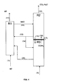
- the figure 3 represents a variant of the process described on the figure 1 wherein a portion of the stream from the WGS water gas shift unit feeds a PC fuel cell. Possibly part of the synthesis gas from reactor R3 via line (8) also feeds the fuel cell to produce electricity and / or heat.
- the figure 4 represents the configuration in which the gasification reaction and the reduction reaction are carried out in the same reactor, in two separate reaction zones R3 and R2.
- the oxidizing mass in its most oxidized form (12) enters the reduction zone R2 where it is brought into contact with the gases (19) coming from the zone R3 containing at least partly a mixture (CO, H2 ) which will be oxidized to CO2, H2O.
- the oxidizing masses will also complete the combustion of hydrocarbons from the zone R3 present in the gas phase (19).
- the fumes of R2 are discharged through a conduit (16) and essentially contain water and CO2. The water can then be condensed and the CO 2 sent transported to a storage place after a possible post-treatment allowing for example to purify the CO 2 by desulfurizing the fumes.
- the oxidizing masses of the zone R2 are then directed to the zone R3 in which the combustion of the fuel (4) is carried out by the lines (15) or (14). Part of the oxidizing masses may optionally be returned to the air reactor (R1).
- One of the features of the invention consists in arranging the zones R2 and R3 one above the other. It is then possible thanks to particular devices to allow all the gases from R3 to pass into R2 and the solids from R2 to flow into R3 so that the fuel contacts the counter-current oxidizing mass as represented on the figure 4 .
- These particular devices well known to those skilled in the art are for example internal such as perforated plates or baffles.
- the figure 5 represents the process according to the invention in the same configuration as the figure 1 , in the case of the example given below.
- the reactions in the "air” (R1), fuel (R2) and gasification (R3) reactors take place at a temperature of between 700 ° C. and 1200 ° C., very preferably between 750 and 950 ° C.
- the residence time of the metal oxides in the fuel reactor (R2) depends on the nature of the fuel and can be estimated generally between 30 s and 10 minutes, preferably between 1 and 8 minutes.
- the residence time of the metal oxides in the air reactor (R1) depends on the oxidation state and / or reduction of these oxides and can be estimated generally between 30 seconds and 10 minutes, preferably between 1 and 3 minutes. .
- the residence time of the metal oxides in the gasification reactor depends on the nature of the fuel to be gasified and can be estimated generally between 1 and 20 minutes, preferably between 1.5 minutes and 10 minutes.
- the invention makes it possible, by using chemical looping oxidizing masses, to combine the production of energy and the production of hydrogen (or more generally of synthesis gas) in the same chemical loop.
- the chemical loop of the process according to the invention makes it possible not only to produce the energy necessary for the production of synthesis gas, but possibly also to produce exploitable energy in the form of heat and / or electricity.
- the optional addition of a portion of the synthesis gas produced in the gasification reactor to the reduction reactor induces exothermic reactions in this reactor, further promoting the balance. overall energy efficiency of the invention ( Figure 1 , (11)).
- the process according to the invention allows the use of the catalytic capacity of the reduced metal oxides at the outlet of the reduction reactor (R2) in the gasification reaction (R3).
- the gasification reaction is thus catalyzed by the metal oxides, without external catalyst supply.
- the process according to the invention makes it possible to inject heavy charges directly into contact with the oxygen carrier in the reduction reactor ("fuel reactor" R2).
- the integrated method according to the invention finally makes it possible to avoid residence times of the solid fuels / metal oxides important in the reduction reactor ("reactor fuel”) which are generally of the order of 15 to 20 minutes. Indeed, these residence times are important and usually involve large size reactors.
- the operating conditions considered at each stage are the following:
- the system is considered to be in energy equilibrium, however the system has a dynamic character since the solid oxygen carrier circulates continuously between the different reactors of the system.
- This value does not take into account the catalytic activity of the solid and represents a high estimate of the energy required for gasification.
Description
Compte tenu des évolutions climatiques observées ces dernières décennies et de celles prévisibles à long terme, la maîtrise des émissions de gaz à effet de serre devient une exigence de plus en plus forte pour tous les secteurs économiques, et en particulier ceux concernant la production d'énergie. Une des différentes voies possibles pour maîtriser les rejets de gaz à effet de serre à l'atmosphère est le captage et la séquestration du carbone. Cette option est spécialement adaptée dans le cas de l'utilisation centralisée d'énergies fossiles. La plupart des solutions envisagées induisent une pénalité énergétique importante, avec une autoconsommation de l'ordre de 20 à 30%.Given the climatic changes observed over the last decades and those foreseeable in the long term, the control of greenhouse gas emissions is becoming an increasingly demanding requirement for all economic sectors, and in particular those concerning the production of greenhouse gases. energy. One of the possible ways to control greenhouse gas emissions to the atmosphere is carbon capture and sequestration. This option is especially adapted in the case of the centralized use of fossil energies. Most of the solutions envisaged induce a significant energy penalty, with a self-consumption of the order of 20 to 30%.
Parmi les moyens permettant la capture du CO2 dans les unités de combustion, la boucle chimique, en cours de développement, et que l'on peut classer dans la catégorie des techniques d'oxycombustion, présente l'avantage de produire des fumées de combustion exemptes d'azote venant de l'air de combustion.Among the means for capturing CO 2 in combustion units, the chemical loop, which is under development and which can be classified in the oxyfuel combustion category, has the advantage of producing combustion fumes. free of nitrogen from combustion air.
Ainsi dans l'hypothèse où le gaz, le solide et le liquide brûlent complètement avec de l'oxygène apporté par des particules comme des oxydes métalliques, les fumées seraient seulement composées de CO2 et de vapeur d'eau, qui, une fois refroidies en dessous de 100°C et débarrassées de l'eau condensée, consisteraient en CO2 pur pouvant être séquestré.Thus, assuming that the gas, the solid and the liquid burn completely with oxygen supplied by particles such as metal oxides, the fumes would consist only of CO 2 and water vapor, which, once cooled, below 100 ° C and free of condensed water, would consist of pure CO 2 that can be sequestered.
La combustion en boucle chimique (ou en anglais CLC pour Chemical Looping Combustion), présente un potentiel important en terme d'efficacité énergétique et de réduction des coûts. Ce procédé évite la pénalité énergétique liée à la séparation de l'oxygène de l'air. Il repose sur la capacité de transfert d'oxygène de certains matériaux tels que les oxydes métalliques. Un réacteur à air sert à oxyder les transporteurs d'oxygène préparés sous forme de fines particules qui sont alors transférées dans un réacteur à combustible où elles sont réduites par la combustion du combustible. Ce procédé est généralement imaginé et réalisé à l'échelle pilote sous forme de deux lits fluidisés échangeant des flux de solides : le réacteur à air étant alors un réacteur de type fluidisation rapide au sommet duquel le flux d'air appauvri en oxygène et les particules sont séparés par un cyclone, les particules descendant par gravité dans le réacteur à combustible constitué par un lit fluidisé dense, où un débordement réalise la réinjection des solides au bas du riser, tandis que les gaz de combustion composés essentiellement de CO2 et H2O sont évacués par le ciel de ce lit fluidisé dense. Lorsque la stoechiométrie d'oxygène est en excès par rapport aux besoins requis pour conduire la combustion, la boucle chimique permet d'effectuer une combustion totale du combustible et de produire des fumées contenant essentiellement du CO2 tout en maximisant l'énergie produite. En limitant l'apport d'oxygène, par exemple grâce à un contrôle de la circulation des masses oxydantes, il est également possible de réaliser une combustion partielle du carburant et de produire des fumées constituées au moins en partie d'un mélange CO, H2 qui, après traitement et purification en aval peut servir de charge à des procédés de transformation ou de production d'énergie. Cette combustion partielle limite la production énergétique, mais permet ensuite de valoriser les fumées produites contenant l'hydrogène.Chemical Looping Combustion (CLC) offers significant potential for energy efficiency and cost reduction. This process avoids the energy penalty related to the separation of oxygen from the air. It is based on the oxygen transfer capacity of certain materials such as metal oxides. An air reactor is used to oxidize the oxygen carriers prepared in the form of fine particles which are then transferred into a fuel reactor where they are reduced by fuel combustion. This process is generally imagined and carried out on a pilot scale in the form of two fluidized beds exchanging solids streams: the air reactor then being a fast fluidization type reactor at the top of which the flow of oxygen-depleted air and the particles are separated by a cyclone, the particles descending by gravity in the fuel reactor consists of a dense fluidized bed, where an overflow performs the reinjection of the solids at the bottom of the riser, while the combustion gases composed mainly of CO 2 and H 2 O are evacuated by the sky from this dense fluidized bed. When the oxygen stoichiometry is in excess of the requirements required to drive the combustion, the chemical loop allows for a total combustion of the fuel and produce fumes containing mainly CO 2 while maximizing the energy produced. By limiting the supply of oxygen, for example by controlling the circulation of the oxidizing masses, it is also possible to achieve a partial combustion of the fuel and to produce fumes consisting at least in part of a mixture CO, H2 which, after treatment and downstream purification, can be used as a load for processes of transformation or energy production. This partial combustion limits energy production, but then makes it possible to recover the fumes produced containing hydrogen.
Des essais d'intégration de la boucle chimique dans des installations de conversion d'hydrocarbures ont été mis en oeuvre.Chemical loop integration tests in hydrocarbon conversion plants have been implemented.
Le
Le document
Le document
La production d'hydrogène peut être effectuée par gazéification : la demande de brevet
La présente invention permet de résoudre la plupart des inconvénients évoqués ci-dessus et propose un procédé intégré optimisé en termes de coût énergétique et d'équipements, pour la production simultanée de gaz de synthèse et d'énergie.The present invention makes it possible to solve most of the disadvantages mentioned above and proposes an optimized integrated process in terms of energy cost and equipment, for the simultaneous production of synthesis gas and energy.
L'invention s'appuie sur la production du gaz de synthèse dans une zone réactionnelle de gazéification située entre le réacteur air (ou zone réactionnelle d'oxydation) et le réacteur fioul (ou zone réactionnelle de réduction), en utilisant la capacité catalytique des oxydes métalliques pour abaisser la température ainsi que l'endothermicité de la gazéification et augmenter la vitesse des réactions favorisant la production d'un mélange H2/CO concentré à la sortie.The invention is based on the production of the synthesis gas in a gasification reaction zone situated between the air reactor (or oxidation reaction zone) and the fuel reactor (or reduction reaction zone), by using the catalytic capacity of the metal oxides to lower the temperature as well as the endothermicity of the gasification and increase the rate of reactions favoring the production of a concentrated H2 / CO mixture at the outlet.
Le réacteur air R1 est ici utilisé pour oxyder les oxydes métalliques réduits et fournir de l'énergie, en quantité au moins égale à l'énergie nécessaire à l'activation des réactions de réduction et de gazéification. aucune production de gaz de synthèse ou d'hydrogène n'est réalisée dans ce réacteur.The air reactor R1 is used here to oxidize the reduced metal oxides and provide energy in an amount at least equal to the energy required for the activation of the reduction and gasification reactions. no production of synthesis gas or hydrogen is produced in this reactor.
Les réactions de réduction et de gazéification ont lieu dans deux zones réactionnelles distinctes de la boucle chimique du procédé selon l'invention, respectivement R2 et R3The reduction and gasification reactions take place in two distinct reaction zones of the chemical loop of the process according to the invention, respectively R2 and R3.
Par ailleurs, l'utilisation de la capacité catalytique des transporteurs d'oxygène et, plus spécifiquement, des métaux qu'ils contiennent permet d'accélérer la cinétique des réactions qui ont lieu dans le réacteur de gazéification et de réduire les températures de réactions dans le réacteur de gazéification, en diminuant l'énergie d'activation. Le temps de résidence nécessaire des réactifs s'en trouve réduit. Ceci affecte directement les tailles des installations et plus spécifiquement les tailles des réacteurs mis en jeu. La réduction des températures de fonctionnement dans le réacteur de gazéification induit un meilleur bilan énergétique et une réduction des coûts d'investissement du fait de l'abaissement des contraintes thermo-mécaniques sur les matériaux.Furthermore, the use of the catalytic capacity of the oxygen carriers and, more specifically, the metals they contain makes it possible to accelerate the kinetics of the reactions that take place in the gasification reactor and to reduce the reaction temperatures in the reactor. the gasification reactor, by decreasing the activation energy. The necessary residence time of the reagents is reduced. This directly affects the size of the plants and more specifically the reactor sizes involved. The reduction of the operating temperatures in the gasification reactor induces a better energy balance and a reduction of the investment costs due to the lowering of the constraints. thermo-mechanical on materials.
L'invention concerne un procédé de production de gaz de synthèse dans au moins une boucle chimique comprenant au moins trois zones réactionnelles distinctes d'oxydation, réduction, gazéification, dans lequel :
- a) on effectue l'oxydation des oxydes métalliques réduits MeO1-x dans une zone réactionnelle d'oxydation R1 alimentée par de l'air ;
- b) on effectue la combustion d'une charge hydrocarbonée solide et/ou liquide et/ou gazeuse par réduction au moins partielle des oxydes métalliques MeO dans une zone réactionnelle de réduction R2 pour produire un mélange gazeux CO2/H2O ;
- c) on effectue la gazéification catalytique d'une charge hydrocarbonée solide et/ou liquide au moyen des oxydes métalliques au moins partiellement réduits issus de R2 dans une zone réactionnelle de gazéification R3 pour produire un gaz de synthèse CO+H2;
- a) the oxidation of the reduced metal oxides MeO1-x is carried out in an oxidation reaction zone R1 supplied with air;
- b) the combustion of a solid and / or liquid and / or gaseous hydrocarbon feedstock is carried out by at least partial reduction of the metal oxides MeO in a reduction reaction zone R2 to produce a
gaseous CO 2 / H 2 O mixture; - c) the catalytic gasification of a solid hydrocarbon feedstock and / or liquid by means of the at least partially reduced metal oxides from R2 in a gasification reaction zone R3 to produce a CO + H2 synthesis gas;
Les deux zones réactionnelles R2 et R3 peuvent être situées dans deux réacteurs distincts, ou être deux zones réactionnelles distinctes dans un même réacteur. L'oxygène 02 nécessaire à la gazéification peut être apporté au moins en partie par les oxydes métalliques lorsqu'ils sont partiellement réduits et/ou par apport du mélange gazeux CO2/H2O venant de la zone réactionnelle de réduction R2.The two reaction zones R2 and R3 may be located in two separate reactors, or be two separate reaction zones in the same reactor. The
Dans un mode de réalisation, de l'énergie excédentaire exportable est récupérée par échange de chaleur à l'intérieur des zones réactionnelles ou sur les effluents gazeux.In one embodiment, exportable surplus energy is recovered by heat exchange within the reaction zones or on the gaseous effluents.
Dans le cas où la charge alimentant la zone de gazéification R3 est une charge solide, on effectue avantageusement une séparation entre les cendres et les particules d'oxyde métallique issues de la zone de gazéification R3 et on alimente la zone de réduction R1 avec les particules d'oxydes métalliques séparées.In the case where the feedstock supplying the gasification zone R3 is a solid feedstock, separation between the ashes and the metal oxide particles from the gasification zone R3 is advantageously effected and the reduction zone R1 is fed with the particles. of separate metal oxides.
Dans un mode de réalisation, au moins une partie du gaz de synthèse CO+H2 produit dans la zone de gazéification R3 est introduite dans le réacteur de réduction.In one embodiment, at least a portion of the CO + H2 synthesis gas produced in the gasification zone R3 is introduced into the reduction reactor.
Dans une variante du procédé, au moins une partie du gaz de synthèse CO+H2 produit dans la zone de gazéification R3 et au moins une partie de l'eau provenant de la condensation du flux CO2+H2O issu de la zone de combustion R2 alimentent une unité de water gas shift WGS pour produire CO2 + H2.In a variant of the process, at least a portion of the CO + H2 synthesis gas produced in the gasification zone R3 and at least a portion of the water coming from the condensation of the CO2 + H2O stream from the combustion zone R2 feed a WGS water gas shift unit to produce CO 2 + H2.
Dans une autre variante, les gaz produits dans la zone de gazéification sont, après purification, destinés à alimenter au moins en partie une pile à combustible.In another variant, the gases produced in the gasification zone are, after purification, intended to feed at least partly a fuel cell.
Dans une dernière variante, les gaz produits dans la zone de gazéification sont, après purification, destinés à alimenter au moins en partie une unité de synthèse d'hydrocarbures de type Fischer Tropsch ou une unité de synthèse du méthanol ou une unité de synthèse du diméthyléther.In a last variant, the gases produced in the gasification zone are, after purification, intended to feed at least in part a Fischer Tropsch type hydrocarbon synthesis unit or a methanol synthesis unit or a dimethyl ether synthesis unit. .
L'invention concerne un procédé intégré d'oxydation, réduction et gazéification pour production de gaz de synthèse en boucle chimique.The invention relates to an integrated oxidation, reduction and gasification process for the production of synthesis gas in a chemical loop.
Ce procédé optimisé de combustion en boucle chimique (ou CLC : Chemical Looping Combustion) est adapté à la combustion des hydrocarbures liquides et surtout les résidus lourds et/ou extra-lourds ou bitumeux et intègre une gazéification des combustibles liquides ou solides, ce qui permet la production, simultanée ou non, d'hydrogène (ou de gaz de synthèse) et d'énergie dans la même boucle chimique. La production d'énergie peut être limitée aux besoins énergétiques de la boucle chimique (autosuffisance énergétique), ou excéder ces besoins et permettre une valorisation externe de l'énergie excédentaire produite.This optimized method of chemical looping combustion (or CLC: Chemical Looping Combustion) is suitable for the combustion of liquid hydrocarbons and especially heavy and / or extra-heavy residues or bituminous and includes a gasification of liquid or solid fuels, which allows the production, simultaneous or not, of hydrogen (or synthesis gas) and energy in the same chemical loop. Energy production may be limited to the energy needs of the chemical loop (energy self-sufficiency), or exceed these needs and allow external valorization of the excess energy produced.
La combustion par boucle chimique consiste à mettre en contact une charge hydrocarbonée avec un oxyde métallique à haute température. L'oxyde métallique cède alors une partie de l'oxygène qu'il renferme, qui participe à la combustion des hydrocarbures. A l'issue de cette combustion, les fumées contiennent majoritairement des oxydes de carbone, de l'eau et éventuellement de l'hydrogène. En effet, il n'est pas nécessaire de mettre en contact l'air avec l'hydrocarbure et les fumées sont donc majoritairement composées des gaz de combustion et éventuellement d'un gaz de dilution servant au transport et à la fluidisation des particules (par exemple de la vapeur d'eau). Il est donc possible ainsi de produire des fumées exemptes majoritairement d'azote et contenant des teneurs en CO2 élevées (supérieures à 90% en volume) permettant d'envisager le captage, puis le stockage de CO2. L'oxyde métallique ayant participé à la combustion est ensuite transporté vers une autre enceinte réactionnelle où il est mis en contact avec de l'air pour être réoxydé. Si les particules revenant de la zone de combustion sont exemptes de combustible, les gaz issus de cette zone réactionnelle sont majoritairement exempts de CO2 -qui n'est alors présent qu'à l'état de traces, par exemple à des concentrations inférieures à 1 à 2% en volume- et consistent essentiellement en de l'air appauvri en oxygène, suite à l'oxydation des particules métalliques.Chemical loop combustion involves contacting a hydrocarbon feedstock with a metal oxide at a high temperature. The metal oxide then gives up some of the oxygen it contains, which participates in the combustion of hydrocarbons. At the end of this combustion, the fumes mainly contain carbon oxides, water and possibly hydrogen. Indeed, it is not necessary to put the air in contact with the hydrocarbon and the smoke is therefore mainly composed of combustion gases and possibly a dilution gas used for the transport and fluidization of the particles (by example of water vapor). It is thus possible to produce fumes that are mostly free of nitrogen and contain high CO 2 contents (greater than 90% by volume), making it possible to envisage capture and then storage of CO 2 . The metal oxide that participated in the combustion is then transported to another reaction chamber where it is brought into contact with air to be reoxidized. If the particles returning from the combustion zone are fuel-free, the gases coming from this reaction zone are predominantly free of CO 2 -which is then only present in trace amounts, for example at concentrations below 1 to 2% by volume - and consists essentially of oxygen-depleted air, following the oxidation of the metal particles.
Les charges utilisables pour la combustion en boucle chimique sont d'une manière générale les hydrocarbures (gaz naturel, charges pétrolières liquides, préférentiellement les résidus pétroliers caractérisés par le fait que moins de 10% de ces résidus ont leur point d'ébullition dans les conditions atmosphériques au delà de 350°C, ou encore des résidus de conversion, généralement issus des procédés d'hydroconversion ou les asphaltes, résidus du procédé de désasphaltage, ou des charges solides telles que le charbon ou le coke issu des procédés de cokéfaction).The charges that can be used for the chemical loop combustion are generally hydrocarbons (natural gas, liquid petroleum charges, preferably petroleum residues characterized by the fact that less than 10% of these residues have their boiling point under the conditions atmospheric concentrations above 350 ° C, or conversion residues, generally from hydroconversion processes or asphalts, residues of the deasphalting process, or solid charges such as coal or coke from coking processes).
La mise en oeuvre d'un procédé de combustion en boucle chimique requiert des quantités d'oxydes métalliques importantes au contact du combustible. Ces oxydes métalliques sont généralement soit contenus dans des particules de minerai, soit dans des particules résultant de traitements industriels (résidus de l'industrie sidérurgique ou minière, catalyseurs de l'industrie chimique ou du raffinage usagés). On peut également utiliser des matériaux synthétiques tels que par exemple des supports d'alumine ou de silice alumine sur lesquels on aura déposé des métaux qui peuvent être oxydés (oxyde de nickel par exemple).The implementation of a chemical loop combustion process requires large quantities of metal oxides in contact with the fuel. These metal oxides are generally either contained in ore particles or in particles resulting from industrial processes (residues of the iron and steel or mining industry, catalysts of the used chemical or refining industry). It is also possible to use synthetic materials such as, for example, alumina or silica-alumina supports on which metals which can be oxidized (nickel oxide, for example) have been deposited.
Les oxydes métalliques utilisables pour réaliser la combustion en boucle chimique sont généralement des oxydes du Fe, Ti, Ni, Cu, Mg, Mn, Co, V, utilisés seuls ou en mélange. Ces métaux peuvent être sous la forme de minerais naturels (comme l'ilménite) ou déposés sur un support synthétique ou sur un catalyseur usagé. De préférence, ces solides sont conditionnés sous la forme de poudre, de diamètre de Sauter compris préférentiellement entre 30 et 500 microns, et de masse volumique de grain comprise entre 1400 et 8000 kg/m3, préférentiellement entre 1400 et 5000 kg/m3.The metal oxides that can be used to carry out the chemical loop combustion are generally oxides of Fe, Ti, Ni, Cu, Mg, Mn, Co, V, used alone or as a mixture. These metals may be in the form of natural ores (such as ilmenite) or deposited on a synthetic support or spent catalyst. Preferably, these solids are packaged in the form of powder, Sauter diameter preferably between 30 and 500 microns, and grain density of between 1400 and 8000 kg / m3, preferably between 1400 and 5000 kg / m3.
D'un oxyde métallique à l'autre, la quantité d'oxygène théoriquement disponible varie considérablement et peut atteindre des valeurs élevées voisines de 30%. Selon les matériaux cependant, la capacité maximale d'oxygène réellement disponible n'excède en général pas plus de 20% de l'oxygène présent. La capacité de ces matériaux à céder de l'oxygène n'excède donc au global pas plus de quelques pourcents en poids des particules et varie considérablement d'un oxyde à un autre, généralement de 0,1 à 15%, et souvent entre 0,3 et 13% poids. La mise en oeuvre en lit fluidisé est de ce fait particulièrement avantageuse pour conduire la combustion. En effet, les particules d'oxydes finement divisées circulent plus facilement dans les enceintes réactionnelles de combustion et d'oxydation, et entre ces enceintes, si l'on confère aux particules les propriétés d'un fluide (fluidisation).From one metal oxide to another, the quantity of oxygen theoretically available varies considerably and can reach high values close to 30%. Depending on the materials however, the maximum oxygen capacity actually available generally does not exceed more than 20% of the oxygen present. The ability of these materials to yield oxygen thus does not exceed globally not more than a few percent by weight of the particles and varies considerably from one oxide to another, generally from 0.1 to 15%, and often from 0 to 15%. , 3 and 13% by weight. The use of a fluidized bed is therefore particularly advantageous for conducting combustion. In fact, the finely divided oxide particles circulate more easily in the combustion and oxidation reaction chambers, and between these enclosures, if the particles are given the properties of a fluid (fluidization).
Un porteur d'oxygène est caractérisé par sa capacité de transport d'oxygène, c'est à dire la quantité d'oxygène que ce porteur pourra échanger avec le milieu réactionnel entre son état le plus oxydé et celui le moins oxydé de façon réversible. On définit X comme la fraction de la capacité totale de transfert d'oxygène restante dans l'oxyde et ΔX comme une fraction de la capacité totale de transfert d'oxygène. Un transporteur d'oxygène est un solide qui, en plus de sa capacité de transporter de l'oxygène, va pouvoir relarguer spontanément son oxygène sous forme gazeuse dans le milieu réactionnel sans que ce dernier soit nécessairement réducteur.An oxygen carrier is characterized by its oxygen transport capacity, that is to say the amount of oxygen that this carrier will be able to exchange with the reaction medium between its most oxidized state and the least reversibly oxidized state. X is defined as the fraction of the total oxygen transfer capacity remaining in the oxide and ΔX as a fraction of the total oxygen transfer capacity. An oxygen carrier is a solid which, in addition to its capacity to transport oxygen, will be able to spontaneously release its oxygen in gaseous form into the reaction medium without the latter being necessarily reducing.
La combustion par boucle chimique permet de produire de l'énergie, sous la forme de vapeur ou d'électricité par exemple. La chaleur de combustion de la charge est similaire à celle rencontrée dans la combustion classique. Celle-ci correspond à la somme des chaleurs de réduction et d'oxydation dans la boucle chimique. La répartition entre les chaleurs de réduction et d'oxydation dépend fortement des oxydes métalliques utilisés pour conduire la combustion par boucle chimique. Dans certains cas, l'exothermicité est répartie entre l'oxydation et la réduction du métal. Dans d'autres cas, l'oxydation est fortement exothermique et la réduction est endothermique. Dans tous les cas, la somme des chaleurs d'oxydation et de réduction est égale à la chaleur de combustion du combustible. La chaleur est extraite par des échangeurs situés à l'intérieur, en paroi ou en appendice des enceintes de combustion et/ou d'oxydation, sur les lignes de fumées, ou sur les lignes de transfert d'oxydes métalliques.Chemical loop combustion is used to produce energy, in the form of steam or electricity, for example. The heat of combustion of the load is similar to that encountered in conventional combustion. This corresponds to the sum of the heats of reduction and oxidation in the chemical loop. The distribution between the heats of reduction and oxidation strongly depends on the metal oxides used to drive the combustion by chemical loop. In some cases, exothermicity is distributed between oxidation and metal reduction. In other cases, the oxidation is highly exothermic and the reduction is endothermic. In all cases, the sum of the oxidation and reduction heats is equal to the heat of combustion of the fuel. The heat is extracted by exchangers located inside, on the wall or in the appendix of the combustion and / or oxidation chambers, on the flue gas lines, or on the metal oxide transfer lines.
Le procédé intégré selon l'invention permet la production simultanée de gaz de synthèse et d'énergie dans la même boucle chimique.The integrated process according to the invention allows the simultaneous production of synthesis gas and energy in the same chemical loop.
Le procédé selon l'invention est mis en oeuvre dans au moins une boucle chimique comprenant au moins trois zones réactionnelles distinctes d'oxydation R1, de réduction R2, de gazéification R3.The process according to the invention is carried out in at least one chemical loop comprising at least three distinct reaction zones of oxidation R1, reduction R2 and gasification R3.
De manière avantageuse, pour permettre une valorisation énergétique externe, l'énergie dégagée par l'oxydation des oxydes métalliques dans la zone réactionnelle d'oxydation R1 est supérieure aux sommes des énergies nécessaires aux réactions de gazéification et de réduction qui interviennent respectivement dans la zone de gazéification R3 et la zone de réduction R2.Advantageously, to allow external energy recovery, the energy released by the oxidation of the metal oxides in the oxidation reaction zone R1 is greater than the sum of the energies required for the gasification and reduction reactions which occur respectively in the zone. R3 gasification and the reduction zone R2.
La boucle chimique permettant la mise en oeuvre du procédé selon l'invention comprend trois zones réactionnelles distinctes :
- 1. au moins une zone réactionnelle d'oxydation R1, alimentée par de l'air, dite réacteur "air", où se déroule la réaction d'oxydation des oxydes métalliques après réduction,
- 2. au moins une zone réactionnelle de réduction par combustion R2, dite réacteur "fioul" où se déroule la réaction de combustion des charges en présence de l'oxygène présent dans les oxydes métalliques,
- 3. au moins une zone réactionnelle de gazéification R3, dite "réacteur de gazéification", des charges solides et/ou liquides pour un produire un gaz de synthèse, ladite gazéification étant catalysée par les oxydes métalliques au moins partiellement réduits issus de R2.
- 1. at least one air-supplied oxidation reaction zone R1, called the "air" reactor, where the oxidation reaction of the metal oxides takes place after reduction,
- 2. at least one combustion reduction reaction zone R2, called "fuel" reactor, where the combustion reaction of the charges takes place in the presence of the oxygen present in the metal oxides,
- 3. at least one gasification reaction zone R3, called a "gasification reactor", solid and / or liquid charges for producing a synthesis gas, said gasification being catalyzed by the at least partially reduced metal oxides from R2.
Le dispositif de boucle chimique peut comprendre également :
- 4. un ou plusieurs organes de séparations particules - gaz (cyclone)
- 5. un ou plusieurs organes d'étanchéité dans les conduits de liaison entre chacun des réacteurs permettant la circulation des oxydes métalliques (tel que par exemple des dispositifs tels que des siphons)
- 6. dans le cas de la gazéification des combustibles solides au moins un organe de séparation entre les particules d'oxyde métalliques et les particules de nature différente (cendres, imbrûlés) nécessaire entre le réacteur de gazéification et le réacteur air pour éviter un mélange possible de CO2 avec l'azote dans le réacteur air.
- 4. one or more particle-gas separation members (cyclone)
- 5. one or more sealing members in the connecting ducts between each of the reactors allowing the circulation of the metal oxides (such as for example devices such as siphons)
- 6. in the case of gasification of solid fuels at least one separating member between the metal oxide particles and the particles of different nature (ash, unburnt) required between the gasification reactor and the air reactor to avoid possible mixing of CO 2 with the nitrogen in the air reactor.
Dans une variante du procédé, il est possible d'effectuer la réaction de gazéification et la réaction de réduction dans le même réacteur, dans deux zones réactionnelles distinctes.In a variant of the process, it is possible to carry out the gasification reaction and the reduction reaction in the same reactor in two separate reaction zones.
Dans le procédé selon l'invention, l'énergie dégagée par l'oxydation du transporteur d'oxygène dans le "réacteur air" R1 est au moins égale aux sommes des énergies nécessaires aux réactions de gazéification et de réduction : ainsi, l'énergie dégagée par l'oxydation du transporteur d'oxygène dans le "réacteur air" R1 permet de fournir l'énergie nécessaire à l'activation des réactions de gazéification (R3) et de réduction (R2), mais également de fournir éventuellement une énergie exploitable tant au niveau du procédé que d'un point de vue production d'énergie vers l'extérieur (chaleur et/ ou électricité).In the process according to the invention, the energy released by the oxidation of the oxygen carrier in the "air reactor" R1 is at least equal to the sums of the energies required for the gasification and reduction reactions: thus, the energy released by the oxidation of the oxygen carrier in the "air reactor" R1 can provide the energy required for the activation of the gasification reactions (R3) and reduction (R2), but also to possibly provide a usable energy both in the process and from the point of view of energy production to the outside (heat and / or electricity).
Dans le cas particulier où l'on apporte du gaz de synthèse dans le réacteur de réduction les réactions dans ce réacteur deviennent exothermiques, favorisant ainsi le bilan énergétique global de la boucle chimique.In the particular case in which synthesis gas is supplied to the reduction reactor, the reactions in this reactor become exothermic, thus favoring the overall energy balance of the chemical loop.
Le procédé de l'invention est illustré à titre non limitatif par les
La
Un débit d'oxydes métalliques circule du réacteur d'oxydation (ou "réacteur air") (R1) alimenté en air par une ligne (1) vers le réacteur de réduction (ou "réacteur fioul") (R2) où se déroule la combustion de la charge par réduction des matériaux transporteurs d'oxygène MeO dans leur état d'oxydation maximal, c'est à dire 0,8 ≤ X ≤ 1 et de préférence 0,95 ≤ X ≤ 1, durant une durée précise allant généralement de 1 à 15 minutes. Les oxydes métalliques en sortie du réacteur de réduction R2 (MeO1-x) sont en partie sous forme métallique, avec 0 ≤ X ≤ 0,5 et de préférence 0 ≤ X ≤ 0,1, après réaction entre l'oxygène existant dans leur structure et le combustible solide et/ou liquide et/ou gazeux arrivant par une ligne (2). Ces formes réduites MeO1-x des oxydes métalliques circulent par une ligne (3) du réacteur fuel (R2) vers le réacteur de gazéification (R3) où une réaction de gazéification d'un combustible solide et/ou liquide arrivant par une ligne (4) a lieu. Cette étape de gazéification est catalysée par les oxydes métalliques sous forme réduite MeO1-x' pour lesquels 0 ≤ X ≤ 0,5, et de préférence 0 ≤ X ≤ 0,1. Le réacteur de gazéification est alimenté par un gaz oxydant tel que CO2 ou H2O et/ou un mélange H2O,CO2 provenant au moins en partie de la réaction de combustion ayant lieu dans le réacteur R2. Le réacteur de gazéification (R3) est ainsi alimenté par une ligne (5) par au moins une partie du CO2, H2O et/ou du mélange CO2/H2O provenant de la cheminée du réacteur de réduction (R2). La partie restante du CO2, H2O et/ou du mélange CO2/H2O est envoyée par une ligne (6) vers un condenseur C afin de séparer le CO2 de l'eau. L'eau ainsi séparée peut ainsi alimenter par une ligne (7) une unité de water gas shift WGS qui permet de produire un mélange CO2/H2 à partir du gaz de synthèse arrivant par une ligne (8) depuis le réacteur R3. A la sortie du réacteur R3, les particules solides sont envoyées par une ligne (10) vers un séparateur S afin de séparer les cendres des oxydes métalliques MeO1-x qui sont envoyés vers le réacteur R1.A flow rate of metal oxides flows from the oxidation reactor (or "air reactor") (R1) supplied with air via a line (1) to the reduction reactor (or "oil reactor") (R2) where the reaction takes place. combustion of the charge by reduction of the MeO oxygen-carrying materials in their maximum oxidation state, that is to say 0.8 ≤ X ≤ 1 and preferably 0.95 ≤ X ≤ 1, for a specific duration generally from 1 to 15 minutes. The metal oxides at the outlet of the reduction reactor R2 (MeO 1-x ) are partially in metallic form, with 0 ≤ X ≤ 0.5 and preferably 0 ≤ X ≤ 0.1, after reaction between the oxygen existing in their structure and the solid and / or liquid and / or gaseous fuel arriving via a line (2). These reduced forms MeO 1-x metal oxides circulate through a line (3) of the fuel reactor (R2) to the gasification reactor (R3) where a gasification reaction of a solid and / or liquid fuel arriving via a line ( 4) takes place. This gasification step is catalyzed by the reduced metal oxides MeO 1-x ' for which 0 ≤ X ≤ 0.5, and preferably 0 ≤ X ≤ 0.1. The gasification reactor is fed with an oxidizing gas such as CO 2 or H 2 O and / or a mixture H 2 O, CO 2 originating at least in part from the combustion reaction taking place in the reactor R2. The gasification reactor (R3) is thus supplied by a line (5) with at least a portion of the CO 2 , H 2 O and / or the CO 2 / H 2 O mixture coming from the stack of the reduction reactor (R2) . The remaining portion of the CO 2 , H 2 O and / or CO 2 / H 2 O mixture is sent via a line (6) to a condenser C to separate the CO 2 from the water. The water thus separated can thus supply a line (7) with a WGS water gas shift unit which makes it possible to produce a CO2 / H2 mixture from the synthesis gas arriving via a line (8) from the reactor R3. At the outlet of the reactor R3, the solid particles are sent via a line (10) to a separator S in order to separate the ashes from the metal oxides MeO 1 -x which are sent to the reactor R1.
Le dispositif peut être complété également par des unités de traitement de soufre sous forme H2S et/ou SO2 si le combustible contient du soufre ainsi que d'une unité de séparation CO2 - H2. Ces dispositifs ne sont pas représentés sur les figures. En fonction de la destination des gaz issus du procédé, on purifiera les gaz pour désulfurer les fumées en utilisant les procédés connus de l'homme du métier pour atteindre les spécifications requises pour les applications en aval du procédé décrit dans l'invention.The device can also be completed by sulfur treatment units in H 2 S and / or SO 2 form if the fuel contains sulfur as well as a CO 2 - H 2 separation unit. These devices are not shown in the figures. Depending on the destination of the gases from the process, the gases will be purified to desulphurize the fumes using the methods known to those skilled in the art to achieve the specifications required for downstream applications of the process described in the invention.
Dans le réacteur dit "réacteur fuel" R2, s'effectue la réduction des matériaux dits "matériaux transporteur d'oxygène" par contact entre les matériaux et le combustible liquide et/ou gaz et/ou solide arrivant par la ligne (2).In the so-called "reactor fuel" reactor R2, is carried out the reduction of materials known as "oxygen-carrying materials" by contact between the materials and the liquid fuel and / or gas and / or solid arriving via line (2).
Dans le réacteur dit "réacteur de gazéification" R3, s'effectue la gazéification d'un résidu liquide ou solide (à titre d'exemple) qui est valorisé sous forme de gaz de synthèse CO/H2 aux conditions (température, pression, nombre de moles d'eau par mole de combustible) nécessaires à la gazéification et en présence des matériaux MeO1-x réduits qui ont des propriétés catalytiques.In the so-called "gasification reactor" R3, the gasification of a liquid or solid residue (for example) which is recovered in the form of synthesis gas is carried out. CO / H2 at conditions (temperature, pressure, number of moles of water per mole of fuel) required for gasification and in the presence of reduced MeO 1-x materials which have catalytic properties.
Dans le réacteur dit "réacteur air" R1, les matériaux MeO1-x réduits sont oxydés par l'air, de façon à retrouver leur état le plus oxydé pour lequel 0,8 ≤ X ≤ 1,0, et de préférence 0,95 ≤ X ≤ 1.In the so-called "air reactor" reactor R1, the reduced MeO 1-x materials are oxidized by air, so as to return to their most oxidized state for which 0.8 ≤ X ≤ 1.0, and preferably 0, 95 ≤ X ≤ 1.
La
La
La
Dans cette configuration, la masse oxydante dans sa forme la plus oxydée (12) entre dans la zone de réduction R2 où elle est mise au contact des gaz (19) provenant de la zone R3 contenant au moins en partie un mélange (CO, H2) qui va être oxydé en CO2, H2O. Les masses oxydantes vont par ailleurs parachever la combustion des hydrocarbures issus de la zone R3 présents dans la phase gazeuse (19). Les fumées de R2 sont évacuées par un conduit (16) et contiennent essentiellement de l'eau et du CO2. L'eau peut ensuite être condensée et le CO2 envoyé transporté vers un lieu de stockage après un post-traitement éventuel permettant par exemple de purifier le CO2 en désulfurant les fumées.In this configuration, the oxidizing mass in its most oxidized form (12) enters the reduction zone R2 where it is brought into contact with the gases (19) coming from the zone R3 containing at least partly a mixture (CO, H2 ) which will be oxidized to CO2, H2O. The oxidizing masses will also complete the combustion of hydrocarbons from the zone R3 present in the gas phase (19). The fumes of R2 are discharged through a conduit (16) and essentially contain water and CO2. The water can then be condensed and the CO 2 sent transported to a storage place after a possible post-treatment allowing for example to purify the CO 2 by desulfurizing the fumes.
Les masses oxydantes de la zone R2 sont alors dirigées vers la zone R3 dans laquelle on effectue la combustion partielle du combustible (4) par les lignes (15) ou (14). Une partie des masses oxydantes peut optionnellement être renvoyée dans le réacteur air (R1).The oxidizing masses of the zone R2 are then directed to the zone R3 in which the combustion of the fuel (4) is carried out by the lines (15) or (14). Part of the oxidizing masses may optionally be returned to the air reactor (R1).
Une des caractéristiques de l'invention consiste à agencer les zones R2 et R3 l'une au-dessus de l'autre. Il est alors possible grâce à des dispositifs particuliers de permettre à tous les gaz issus de R3 de passer dans R2 et aux solides issus de R2 de couler dans R3 pour que le combustible contacte la masse oxydante à contre courant comme représenté sur la
Le solide issu de R3 est recyclé vers R1 par la ligne (20).The solid from R3 is recycled to R1 by the line (20).
La
Avantageusement, les réactions dans les réacteurs "air" (R1), fuel (R2) et gazéification (R3) ont lieu à une température comprise entre 700°C et 1200°C, de manière très préférée entre 750 et 950°C.Advantageously, the reactions in the "air" (R1), fuel (R2) and gasification (R3) reactors take place at a temperature of between 700 ° C. and 1200 ° C., very preferably between 750 and 950 ° C.
Le temps de séjour des oxydes métalliques dans le réacteur fuel (R2) dépend de la nature du combustible et peut être estimé de manière générale entre 30 s et 10 minutes, préférentiellement compris entre 1 et 8 minutes.The residence time of the metal oxides in the fuel reactor (R2) depends on the nature of the fuel and can be estimated generally between 30 s and 10 minutes, preferably between 1 and 8 minutes.
Le temps de séjour des oxydes métalliques dans le réacteur air (R1) dépend de l'état d'oxydation et/ou réduction de ces oxydes et peut être estimé de manière générale entre 30 s et 10 minutes, préférentiellement compris entre 1 et 3 min.The residence time of the metal oxides in the air reactor (R1) depends on the oxidation state and / or reduction of these oxides and can be estimated generally between 30 seconds and 10 minutes, preferably between 1 and 3 minutes. .
Le temps de séjour des oxydes métalliques dans le réacteur de gazéification dépend de la nature du combustible à gazéifier et peut être estimé de manière générale entre 1 et 20 minutes, préférentiellement compris entre 1,5 minutes et 10 minutes.The residence time of the metal oxides in the gasification reactor depends on the nature of the fuel to be gasified and can be estimated generally between 1 and 20 minutes, preferably between 1.5 minutes and 10 minutes.
Plusieurs avantages spécifiques du procédé selon l'invention sont cités ci-dessous, à titre non limitatif.Several specific advantages of the method according to the invention are cited below, without limitation.
L'invention permet, grâce à l'utilisation de masses oxydantes en boucle chimique de combiner la production d'énergie et la production d'hydrogène (ou plus généralement de gaz de synthèse) dans la même boucle chimique.The invention makes it possible, by using chemical looping oxidizing masses, to combine the production of energy and the production of hydrogen (or more generally of synthesis gas) in the same chemical loop.
La boucle chimique du procédé selon l'invention permet non seulement de produire l'énergie nécessaire pour la production de gaz de synthèse, mais éventuellement de produire également de l'énergie exploitable sous forme de chaleur et/ou d'électricité.The chemical loop of the process according to the invention makes it possible not only to produce the energy necessary for the production of synthesis gas, but possibly also to produce exploitable energy in the form of heat and / or electricity.
Par ailleurs, dans un mode de réalisation particulier de l'invention, l'apport optionnel d'une partie du gaz de synthèse produit dans le réacteur de gazéification vers le réacteur de réduction, induit des réactions exothermiques dans ce réacteur, favorisant encore le bilan énergétique global de l'invention (
Le procédé selon l'invention permet l'utilisation de la capacité catalytique des oxydes métalliques réduits en sortie du réacteur de réduction (R2) dans la réaction de gazéification (R3). La réaction de gazéification est donc catalysée par les oxydes métalliques, sans apport externe de catalyseur.The process according to the invention allows the use of the catalytic capacity of the reduced metal oxides at the outlet of the reduction reactor (R2) in the gasification reaction (R3). The gasification reaction is thus catalyzed by the metal oxides, without external catalyst supply.
Par ailleurs, le procédé selon l'invention permet d'injecter directement des charges lourdes en contact avec le transporteur d'oxygène dans le réacteur de réduction ("réacteur fuel" R2).Moreover, the process according to the invention makes it possible to inject heavy charges directly into contact with the oxygen carrier in the reduction reactor ("fuel reactor" R2).
Le procédé intégré selon l'invention permet enfin d'éviter des temps de séjour des combustibles solides/oxydes métalliques importants dans le réacteur de réduction ("réacteur fuel") qui sont généralement de l'ordre de 15 à 20 minutes. En effet, ces temps de séjour sont importants et impliquent usuellement des réacteurs de tailles importantes.The integrated method according to the invention finally makes it possible to avoid residence times of the solid fuels / metal oxides important in the reduction reactor ("reactor fuel") which are generally of the order of 15 to 20 minutes. Indeed, these residence times are important and usually involve large size reactors.
L'exemple ci-dessous (représenté sur la
- dans le réacteur dit "réacteur fuel", s'effectue la réduction des matériaux dits "matériaux transporteur d'oxygène" par contact entre les matériaux et un combustible liquide et/ou gaz et/ou solide.
- dans un réacteur distinct, dit "réacteur de gazéifcation", s'effectue la gazéification d'un combustible (un résidu liquide ou solide, à titre d'exemple) qui est valorisé sous forme de gaz de synthèse aux conditions (T et P, nombre de moles d'eau pour 1 mole de combustible) de gazéification et en présence des matériaux réduits qui ont des propriétés catalytiques.
- dans le réacteur dit "réacteur air", les matériaux réduits seront oxydés par l'air.
- in the so-called "reactor fuel" reactor, is carried out the reduction of so-called materials "oxygen carrier materials" by contact between the materials and a liquid fuel and / or gas and / or solid.
- in a separate reactor, the so-called "gasification reactor", the gasification of a fuel (a liquid or solid residue, for example) which is valorised in the form of synthesis gas at the conditions (T and P, number of moles of water per 1 mole of gasification fuel and in the presence of reduced materials which have catalytic properties.
- in the reactor called "air reactor", the reduced materials will be oxidized by air.
Dans cet exemple sont calculés un bilan énergétique et un bilan matière représentant le système à l'équilibre énergétique, c'est-à-dire dans une situation où l'énergie dégagée par l'oxydation du transporteur d'oxygène dans le "réacteur air" est suffisante non seulement pour activer les réactions de gazéification et de réduction, mais aussi pour fournir une chaleur exploitable tant au niveau du procédé que d'un point de vue production de chaleur.In this example are calculated an energy balance and a material balance representing the energy equilibrium system, that is to say in a situation where the energy released by the oxidation of the oxygen carrier in the "air reactor" "is sufficient not only to activate the gasification and reduction reactions, but also to provide usable heat both in the process and from a heat production point of view.
Les conditions opératoires considérées à chaque étape sont les suivantes :The operating conditions considered at each stage are the following:
- 1) la réaction de gazéification est complète : CO et H2 sont les produits uniques de la réaction.1) the gasification reaction is complete: CO and H 2 are the unique products of the reaction.
- 2) les paramètres de fluidisation ne sont pas pris en compte.2) the fluidization parameters are not taken into account.
- 3) les réactifs sont des combustibles solides et/ou liquide et la vapeur d'eau.3) Reagents are solid and / or liquid fuels and water vapor.
- 4) la réaction est endothermique.4) the reaction is endothermic.
- 1) la réaction de réduction est complète par rapport au combustible. Les produits de la réaction sont du CO2 et de H2O.1) The reduction reaction is complete with respect to the fuel. The products of the reaction are CO 2 and H 2 O.
- 2) L'échange est idéal entre le transporteur d'oxygène et le combustible liquide : il n'y a pas de limitation diffusionnelle, pas de formation de carbone, pas de perte de réactivité.2) The exchange is ideal between the oxygen carrier and the liquid fuel: there is no diffusion limitation, no carbon formation, no loss of reactivity.
- 3) la réaction est endothermique.3) the reaction is endothermic.
- 7. la réaction d'oxydation est complète7. The oxidation reaction is complete
- 8. échange idéal entre le transporteur d'oxygène et l'air8. ideal exchange between the oxygen carrier and the air
- 9. la réaction est exothermique9. the reaction is exothermic
D'une façon plus particulière, le présent exemple considère :
- la combustion du combustible liquide C19H30, qui constitue en première approche un cas similaire au fioul domestique;
- le choix de NiO comme transporteur d'oxygène, la réaction complète de réduction est alors :
53NiO + C19H30 -> 19CO2 + 15H2O + 53Ni
- la forme réduite du transporteur d'oxygène comme étant Ni, la réaction complète d'oxydation est alors :
Ni + 0,5O2 → NiO
- la gazéification est menée à pression atmosphérique.
- the combustion of the liquid fuel C 19 H 30 , which constitutes at first approach a case similar to domestic fuel oil;
- the choice of NiO as oxygen carrier, the complete reduction reaction is then:
53NiO + C 19 H 30 -> 19CO 2 + 15H 2 O + 53Ni
- the reduced form of the oxygen carrier as Ni, the complete oxidation reaction is then:
Ni + 0.5O 2 → NiO
- gasification is conducted at atmospheric pressure.
Le système est considéré comme étant à l'équilibre énergétique, cependant le système a un caractère dynamique puisque le transporteur d'oxygène solide circule en continu entre les différents réacteurs du système. Dans les calculs, on s'intéresse à l'évolution des propriétés de la quantité de transporteur d'oxygène solide nécessaire à la conversion de 100 Nm3/h de charge liquide C19H30 vaporisée.The system is considered to be in energy equilibrium, however the system has a dynamic character since the solid oxygen carrier circulates continuously between the different reactors of the system. In the calculations, we are interested in the evolution of the properties of the amount of solid oxygen carrier required for the conversion of 100 Nm 3 / h of vaporized liquid feed C 19 H 30 .
Valeurs numériques :
Dans le réacteur fuel
53NiO + C19H30 -> 19CO2 + 15H2O + 53Ni
Δ Hr(fuel) = 2266 kJ/molC19H30 = 52,7 kJ/molNIO In the fuel reactor
53NiO + C 19 H 30 -> 19CO 2 + 15H 2 O + 53Ni
ΔH r (fuel) = 2266 kJ / mol C19H30 = 52.7 kJ / mol NIO
Calcul de la quantité de solide ṁNiO requise pour convertir 100 Nm3/h de combustible vaporisé :
- dans les conditions stoechiométriques (C/O=0.36)


ṁi le flux massique du composé i
ṅi le flux massique du composé i
Mi la masse molaire du composé i
- under stoichiometric conditions (C / O = 0.36)
ṁ i the mass flow of the compound i
ṅ i the mass flow of the compound i
M i the molar mass of the compound i
Avec un RoDX (masse d'oxygène mobilisable par gramme de catalyseur) de 0.01 gO/gNiO. ![]()
![]()
![]()
![]()
Dans le réacteur de gazéification :
19H2O + C19H30 -> 19CO + 34H2
Δ Hr(gazéification) = 3130 kJ/molC19H30
puissance nécessaire à la conversion de 50 Nm3/h ![]()
19H 2 O + C 19 H 30 -> 19CO 2 + 34H
Δ H r (gasification) = 3130 kJ / mol C19H30
power required for the conversion of 50 Nm 3 / h ![]()
Cette valeur ne prend pas en compte l'activité catalytique du solide et représente une estimation haute de l'énergie nécessaire à la gazéification.This value does not take into account the catalytic activity of the solid and represents a high estimate of the energy required for gasification.
Dans le réacteur air :
Ni + 0,5O2 -> NiO
Δ Hr(oxydation) = -240 kJ/molNI
puissance fournie par la régénération de 65,7 mol/s de catalyseur par oxydation : ![]()
Ni + 0.5O 2 -> NiO
Δ H r (oxidation) = -240 kJ / mol NI
power provided by the regeneration of 65.7 mol / s of catalyst by oxidation: ![]()
Le calcul ainsi détaillé (voir ci-dessus) permet d'établir un bilan énergétique des réactions qui ont lieu dans les différents réacteurs de l'invention. Ce bilan ne tient compte que des chaleurs de réactions. Le bilan global tenant compte des chaleurs nécessaires pour chauffer les réactifs ainsi que de la chaleur récupérable sur les fluides en sortie des réacteurs mis en jeu, soit:
- P = - 6,7 MW th pour une quantité de solide circulant de 379,2 t/h.
- P = - 6.7 MW th for a circulating solid quantity of 379.2 t / h.
Claims (10)
- A method of producing syngas in at least one chemical loop comprising at least three distinct oxidation, reduction, gasification reaction zones, comprising:1. carrying out oxidation of the reduced metallic oxides MeO1-x in an air-supplied oxidation reaction zone R1 ;2. carrying out combustion of a solid and/or liquid and/or gaseous hydrocarbon feed through at least partial reduction of the metallic oxides MeO in a reduction reaction zone R2 so as to produce a gaseous CO2/H2O mixture ;3. carrying out catalytic gasification of a solid and/or liquid hydrocarbon feed by means of the at least partly reduced metallic oxides from R2 in a gasification reaction zone R3 so as to produce a CO + H2 syngas ;
and wherein the energy released through oxidation of the metallic oxides in oxidation reaction zone R1 allows the gasification and reduction reactions to be activated. - A method as claimed in claim 1, wherein the two reaction zones R2 and R3 are located in two distinct reactors.
- A method as claimed in claim 1, wherein the two reaction zones R2 and R3 are two distinct reaction zones in a single reactor.
- A method as claimed in any one of the previous claims, wherein the oxygen O2 required for gasification is provided at least partly by the metallic oxides when they are partly reduced and/or by the CO2/H2O gaseous mixture from reduction reaction zone R2.
- A method as claimed in any one of the previous claims, wherein the exportable excess energy is recovered by heat exchange within the reaction zones or on the gaseous effluents.
- A method as claimed in any one of the previous claims wherein, in cases where the feed supplying gasification zone R3 is a solid feed, separation is performed between the ashes and the metallic oxide particles from gasification zone R3, and reduction zone R1 is supplied with the separated metallic oxide particles.
- A method as claimed in any one of the previous claims, wherein at least part of the CO + H2 syngas produced in gasification zone R3 is fed into the reduction reactor.
- A method as claimed in any one of the previous claims, wherein at least part of the CO + H2 syngas produced in gasification zone R3 and at least part of the water resulting from the condensation of the CO2 + H2O stream from combustion zone R2 supply a water gas shift unit WGS in order to produce CO2 + H2.
- Use of the method as claimed in any one of claims 1 to 8, wherein the gases produced in the gasification zone are, after purification, intended to be fed at least partly into a fuel cell.
- Use of the method as claimed in any one of claims I to 8, wherein the gases produced in the gasification zone are, after purification, intended to be fed at least partly into a Fischer-Tropsch type hydrocarbon synthesis unit or a methanol synthesis unit or a dimethylether synthesis unit.
Priority Applications (1)
| Application Number | Priority Date | Filing Date | Title |
|---|---|---|---|
| PL10705901T PL2391695T3 (en) | 2009-01-30 | 2010-01-28 | Integrated oxidation, reduction, and gasification method for producing a synthetic gas and energy in a chemical loop |
Applications Claiming Priority (2)
| Application Number | Priority Date | Filing Date | Title |
|---|---|---|---|
| FR0900390A FR2941689B1 (en) | 2009-01-30 | 2009-01-30 | INTEGRATED OXIDATION, REDUCTION AND GASIFICATION PROCESS FOR THE PRODUCTION OF CHEMICAL LOOP SYNTHESIS GAS |
| PCT/FR2010/000069 WO2010086529A1 (en) | 2009-01-30 | 2010-01-28 | Integrated oxidation, reduction, and gasification method for producing a synthetic gas and energy in a chemical loop |
Publications (2)
| Publication Number | Publication Date |
|---|---|
| EP2391695A1 EP2391695A1 (en) | 2011-12-07 |
| EP2391695B1 true EP2391695B1 (en) | 2013-06-26 |
Family
ID=41110831
Family Applications (1)
| Application Number | Title | Priority Date | Filing Date |
|---|---|---|---|
| EP10705901.6A Not-in-force EP2391695B1 (en) | 2009-01-30 | 2010-01-28 | Integrated oxidation, reduction, and gasification method for producing a synthetic gas and energy in a chemical loop |
Country Status (10)
| Country | Link |
|---|---|
| US (1) | US8916128B2 (en) |
| EP (1) | EP2391695B1 (en) |
| CN (1) | CN102300962A (en) |
| AU (1) | AU2010209592A1 (en) |
| CA (1) | CA2750693A1 (en) |
| ES (1) | ES2424802T3 (en) |
| FR (1) | FR2941689B1 (en) |
| PL (1) | PL2391695T3 (en) |
| WO (1) | WO2010086529A1 (en) |
| ZA (1) | ZA201105428B (en) |
Cited By (1)
| Publication number | Priority date | Publication date | Assignee | Title |
|---|---|---|---|---|
| CN106675655A (en) * | 2016-12-06 | 2017-05-17 | 西安交通大学 | Device and method for biomass chemical chain gasification hydrogen production based on calcium-based carbon supporting body |
Families Citing this family (43)
| Publication number | Priority date | Publication date | Assignee | Title |
|---|---|---|---|---|
| CN102186955B (en) | 2008-09-26 | 2015-09-02 | 俄亥俄州立大学 | Carbonaceous fuel is converted into carbon-free energy carrier |
| EP2483371B1 (en) | 2009-09-08 | 2017-11-08 | The Ohio State University Research Foundation | Synthetic fuels and chemicals production with in-situ co2 capture |
| AU2010292313B2 (en) | 2009-09-08 | 2015-08-20 | The Ohio State University Research Foundation | Integration of reforming/water splitting and electrochemical systems for power generation with integrated carbon capture |
| FR2955854B1 (en) | 2010-02-01 | 2014-08-08 | Cotaver | METHOD AND SYSTEM FOR PRODUCING HYDROGEN FROM CARBONACEOUS RAW MATERIAL |
| FR2955865B1 (en) | 2010-02-01 | 2012-03-16 | Cotaver | PROCESS FOR RECYCLING CARBON DIOXIDE (CO2) |
| FR2955918B1 (en) * | 2010-02-01 | 2012-08-03 | Cotaver | METHOD AND SYSTEM FOR PRODUCING A THERMODYNAMIC ENERGY SOURCE BY CONVERTING CO2 TO CARBONIC RAW MATERIALS |
| FR2955866B1 (en) | 2010-02-01 | 2013-03-22 | Cotaver | METHOD AND SYSTEM FOR SUPPLYING THERMAL ENERGY OF A THERMAL TREATMENT SYSTEM AND INSTALLATION USING SUCH A SYSTEM |
| WO2012064712A1 (en) | 2010-11-08 | 2012-05-18 | The Ohio State University | Circulating fluidized bed with moving bed downcomers and gas sealing between reactors |
| EP2484971A1 (en) | 2011-02-04 | 2012-08-08 | Paul Scherrer Institut | A process and a system for the gasification and/or combustion of biomass and/or coal with an at least partial carbon dioxide separation |
| CN103635673B (en) | 2011-05-11 | 2016-05-04 | 俄亥俄州国家创新基金会 | Oxygen carrier material |
| US9903584B2 (en) | 2011-05-11 | 2018-02-27 | Ohio State Innovation Foundation | Systems for converting fuel |
| FR2980258B1 (en) * | 2011-09-20 | 2017-12-29 | Ifp Energies Now | CHEMICAL LOOP COMBUSTION PROCESS WITH REMOVAL OF ASHES AND FINES IN THE REDUCTION AREA AND INSTALLATION USING SUCH A METHOD |
| FR2983488B1 (en) * | 2011-12-02 | 2013-11-15 | IFP Energies Nouvelles | CHEMICAL LOOP COMBUSTION PROCESS WITH REMOVAL OF ASHES AND FINISHES EXIT FROM OXIDATION AREA AND INSTALLATION USING SUCH A METHOD |
| FR2983489B1 (en) | 2011-12-02 | 2013-11-15 | IFP Energies Nouvelles | CHEMICAL LOOP COMBUSTION PROCESS WITH DILUTE PHASE REMOVAL OF ASHES AND FINESS IN OXIDATION AREA AND INSTALLATION USING SUCH A METHOD |
| FR2985517B1 (en) * | 2012-01-11 | 2018-05-18 | Ifp Energies Now | INTEGRATED METHOD OF GASIFYING AND INDIRECT COMBUSTION OF HYDROCARBON FILLERS SOLID IN CHEMICAL LOOP |
| FR2986800B1 (en) | 2012-02-09 | 2015-01-30 | Cotaver | PROCESS, SYSTEM AND SYSTEM FOR TREATING LIQUID AND / OR PASSIZED HYDROCARBON MATERIALS |
| JP6197044B2 (en) * | 2012-11-30 | 2017-09-13 | サウジ アラビアン オイル カンパニー | Stepwise chemical looping process with integrated oxygen production |
| CN109536210B (en) | 2013-02-05 | 2020-12-18 | 俄亥俄州国家创新基金会 | Method for conversion of carbonaceous fuels |
| CN103087776B (en) * | 2013-02-18 | 2014-09-03 | 上海锅炉厂有限公司 | Chemical Iooping combustion-based dry pulverized coal pressurized entrained-flow bed gasification method and chemical Iooping combustion-based dry pulverized coal pressurized entrained-flow bed gasification device |
| WO2014152914A1 (en) * | 2013-03-14 | 2014-09-25 | Ohio State Innovation Foundation | Systems and methods for converting carbonaceous fuels |
| US9481837B2 (en) * | 2013-03-15 | 2016-11-01 | The Babcock & Wilcox Company | Chemical looping processes for partial oxidation of carbonaceous fuels |
| FR3004126B1 (en) * | 2013-04-05 | 2016-01-01 | IFP Energies Nouvelles | METHOD AND DEVICE FOR CHEMICAL BUCKLE COMBUSTION OF LIQUID HYDROCARBON LOADS |
| KR101458872B1 (en) | 2013-07-03 | 2014-11-07 | 한국에너지기술연구원 | Chemical looping combustion method and apparatus for solid fuels using different oxygen carriers |
| US20150238915A1 (en) | 2014-02-27 | 2015-08-27 | Ohio State Innovation Foundation | Systems and methods for partial or complete oxidation of fuels |
| NO338230B1 (en) * | 2014-04-03 | 2016-08-08 | Sinvent As | Fully integrated redox-assisted gasification (RAG) for productive conversion of carbonaceous material |
| US9790437B2 (en) | 2014-10-09 | 2017-10-17 | Saudi Arabian Oil Company | Integrated heavy liquid fuel coking with chemical looping concept |
| FR3029979B1 (en) | 2014-12-12 | 2019-04-05 | IFP Energies Nouvelles | METHOD AND INSTALLATION OF COMBUSTION BY OXYDO-CHEMICAL LOOP REDUCTION OF A GAS HYDROCARBONATED LOAD WITH IN SITU CATALYTIC REFORMING OF THE LOAD |
| FR3030018B1 (en) * | 2014-12-12 | 2017-01-20 | Ifp Energies Now | OXYDO COMBUSTION COMBUSTION INSTALLATION AND METHOD FOR CHEMICAL LOOP REDUCTION OF A GAS HYDROCARBONATED LOAD WITH CATALYTIC PRE-REFORMING OF THE LOAD |
| FR3029906B1 (en) | 2014-12-12 | 2017-01-13 | Ifp Energies Now | METHOD AND INSTALLATION OF COMBUSTION BY OXYDO-CHEMICAL LOOP REDUCTION OF A GAS HYDROCARBONATED LOAD WITH INTERMEDIATE CATALYTIC VAPOREFORMING OF THE LOAD |
| US9902615B2 (en) * | 2015-07-14 | 2018-02-27 | The Babcock & Wilcox Company | Syngas production via cyclic reduction and oxidation of metal oxides |
| AU2017250214B2 (en) | 2016-04-12 | 2021-08-12 | Ohio State Innovation Foundation | Chemical looping syngas production from carbonaceous fuels |
| CN106190195B (en) | 2016-06-29 | 2019-01-25 | 清华大学 | A kind of biomass pyrolytic-burning chemistry chains prepare the device and method of high-purity hydrogen |
| AU2018312361B2 (en) | 2017-07-31 | 2021-11-18 | Ohio State Innovation Foundation | Reactor system with unequal reactor assembly operating pressures |
| US10549236B2 (en) | 2018-01-29 | 2020-02-04 | Ohio State Innovation Foundation | Systems, methods and materials for NOx decomposition with metal oxide materials |
| US11413574B2 (en) | 2018-08-09 | 2022-08-16 | Ohio State Innovation Foundation | Systems, methods and materials for hydrogen sulfide conversion |
| US11549432B2 (en) | 2018-09-21 | 2023-01-10 | King Fahd University Of Petroleum And Minerals | Integrated chemical looping combustion system and method for power generation and carbon dioxide capture |
| KR20200039499A (en) | 2018-10-07 | 2020-04-16 | 정동규 | Integrated gasification process for syngas power generation with checmical looping combustion method |
| CN109401789A (en) * | 2018-11-07 | 2019-03-01 | 华南农业大学 | A kind of biomass chemical chain gasification reforms the device and method of step producing synthesis gas and hydrogen-rich gas |
| WO2020175426A1 (en) * | 2019-02-27 | 2020-09-03 | 国立大学法人東北大学 | Low-temperature hydrocarbon reforming system and method for manufacturing hydrogen and/or syngas at low temperature |
| AU2020271068A1 (en) | 2019-04-09 | 2021-09-30 | Ohio State Innovation Foundation | Alkene generation using metal sulfide particles |
| US11371394B2 (en) | 2019-07-03 | 2022-06-28 | King Fahd University Of Petroleum And Minerals | Methods and systems for diesel fueled CLC for efficient power generation and CO2 capture |
| US11591531B2 (en) | 2020-08-21 | 2023-02-28 | ExxonMobil Technology and Engineering Company | Conversion of catalytic coke into synthetic gas from a fluid catalytic cracking (FCC) process using a chemical looping system and methods related thereto |
| US11667728B1 (en) * | 2022-03-02 | 2023-06-06 | David T. Camp | Reactor and processes for endothermic reactions at high temperatures |
Family Cites Families (8)
| Publication number | Priority date | Publication date | Assignee | Title |
|---|---|---|---|---|
| US4272399A (en) * | 1979-09-21 | 1981-06-09 | Monsanto Company | Conversion of carbon-containing materials to synthesis gas |
| US6669917B2 (en) * | 2001-07-31 | 2003-12-30 | General Electric Co. | Process for converting coal into fuel cell quality hydrogen and sequestration-ready carbon dioxide |
| FR2850156B1 (en) * | 2003-01-16 | 2005-12-30 | Alstom Switzerland Ltd | COMBUSTION INSTALLATION WITH CO2 RECOVERY |
| ES2396541T3 (en) | 2003-09-22 | 2013-02-22 | Dsm Ip Assets B.V. | Food compositions for companion animals that contain vitamins |
| US7767191B2 (en) * | 2003-12-11 | 2010-08-03 | The Ohio State University | Combustion looping using composite oxygen carriers |
| CA2636325C (en) | 2006-01-12 | 2015-04-28 | The Ohio State University | Systems and methods of converting fuel |
| US7824574B2 (en) | 2006-09-21 | 2010-11-02 | Eltron Research & Development | Cyclic catalytic upgrading of chemical species using metal oxide materials |
| US20080134666A1 (en) * | 2006-12-11 | 2008-06-12 | Parag Prakash Kulkarni | Systems and Methods Using an Unmixed Fuel Processor |
-
2009
- 2009-01-30 FR FR0900390A patent/FR2941689B1/en not_active Expired - Fee Related
-
2010
- 2010-01-28 WO PCT/FR2010/000069 patent/WO2010086529A1/en active Application Filing
- 2010-01-28 AU AU2010209592A patent/AU2010209592A1/en not_active Abandoned
- 2010-01-28 CN CN2010800064130A patent/CN102300962A/en active Pending
- 2010-01-28 EP EP10705901.6A patent/EP2391695B1/en not_active Not-in-force
- 2010-01-28 US US13/146,982 patent/US8916128B2/en not_active Expired - Fee Related
- 2010-01-28 ES ES10705901T patent/ES2424802T3/en active Active
- 2010-01-28 PL PL10705901T patent/PL2391695T3/en unknown
- 2010-01-28 CA CA2750693A patent/CA2750693A1/en not_active Abandoned
-
2011
- 2011-07-22 ZA ZA2011/05428A patent/ZA201105428B/en unknown
Cited By (2)
| Publication number | Priority date | Publication date | Assignee | Title |
|---|---|---|---|---|
| CN106675655A (en) * | 2016-12-06 | 2017-05-17 | 西安交通大学 | Device and method for biomass chemical chain gasification hydrogen production based on calcium-based carbon supporting body |
| CN106675655B (en) * | 2016-12-06 | 2019-06-11 | 西安交通大学 | A kind of biomass chemical chain gasification device for producing hydrogen and method based on calcium base carbon carrier |
Also Published As
| Publication number | Publication date |
|---|---|
| ZA201105428B (en) | 2012-03-28 |
| ES2424802T3 (en) | 2013-10-08 |
| FR2941689B1 (en) | 2011-02-18 |
| AU2010209592A1 (en) | 2011-08-18 |
| EP2391695A1 (en) | 2011-12-07 |
| CA2750693A1 (en) | 2010-08-05 |
| US20110303875A1 (en) | 2011-12-15 |
| US8916128B2 (en) | 2014-12-23 |
| WO2010086529A1 (en) | 2010-08-05 |
| WO2010086529A9 (en) | 2011-09-29 |
| PL2391695T3 (en) | 2013-11-29 |
| CN102300962A (en) | 2011-12-28 |
| FR2941689A1 (en) | 2010-08-06 |
Similar Documents
| Publication | Publication Date | Title |
|---|---|---|
| EP2391695B1 (en) | Integrated oxidation, reduction, and gasification method for producing a synthetic gas and energy in a chemical loop | |
| EP2246293B1 (en) | Integrated process for production of energy and/or synthesis gas by production of oxygen in situ, combustion and gasification in a chemical cycle | |
| EP2802638B1 (en) | Integrated method for the chemical-looping gasification and indirect combustion of solid hydrocarbon feedstocks | |
| EP2454525B1 (en) | Method for chemical looping combustion with independent control of the circulation of solids | |
| CN107001950B (en) | Integration of heavy liquid fuel coking and chemical looping concepts | |
| EP3083008B1 (en) | Process and apparatus for cleaning raw product gas | |
| JP2011504196A (en) | Process for producing purified syngas stream | |
| US20150005399A1 (en) | Method and device for producing synthetic gas and method and device for synthesizing liquid fuel | |
| FR2882046A1 (en) | INSTALLATION FOR PRODUCING HYDROGEN OR GAS SYNTHESIS BY GASIFICATION | |
| EP2561043A2 (en) | Integrated process for the treatment and gasification of bituminous feedstocks by chemical looping combustion | |
| EP3230415B1 (en) | Method and installation for combustion via chemical loop oxidation-reduction of hydrocarbon gas feed with an in situ catalytic reforming of the feed | |
| EP2539273A1 (en) | Method for producing synthesis gases | |
| FR3029906A1 (en) | METHOD AND INSTALLATION OF COMBUSTION BY OXYDO-CHEMICAL LOOP REDUCTION OF A GAS HYDROCARBONATED LOAD WITH INTERMEDIATE CATALYTIC VAPOREFORMING OF THE LOAD | |
| EP1575698B1 (en) | Method for generation of a synthesis gas mixture co/h sb 2 /sb under pressure by catalytic partial oxidation with minimisation of the formation of soot | |
| JP5999115B2 (en) | Method and system for reducing the molecular weight of organic substances | |
| EP4085119A1 (en) | Integrated method for thermal conversion and indirect combustion of a heavy hydrocarbon feedstock in a redox chemical loop for producing hydrocarbon streams and capturing the coproduced | |
| FR2995600A1 (en) | PROCESS FOR REDUCING CARBON DIOXIDE OF CARBON MONOXIDE BY VANADIUM OXIDES | |
| CA2861050A1 (en) | Integrated method for the chemical-looping gasification and indirect combustion of solid hydrocarbon feedstocks | |
| JP6248987B2 (en) | Method for reducing the molecular weight of organic substances | |
| Bleeker | Pure hydrogen from pyrolysis oil by the steam-iron process | |
| JP2016038186A (en) | Chemical loop combustion apparatus, power generation apparatus and chemical loop combustion method |
Legal Events
| Date | Code | Title | Description |
|---|---|---|---|
| PUAI | Public reference made under article 153(3) epc to a published international application that has entered the european phase |
Free format text: ORIGINAL CODE: 0009012 |
|
| 17P | Request for examination filed |
Effective date: 20110830 |
|
| AK | Designated contracting states |
Kind code of ref document: A1 Designated state(s): AT BE BG CH CY CZ DE DK EE ES FI FR GB GR HR HU IE IS IT LI LT LU LV MC MK MT NL NO PL PT RO SE SI SK SM TR |
|
| DAX | Request for extension of the european patent (deleted) | ||
| REG | Reference to a national code |
Ref country code: DE Ref legal event code: R079 Ref document number: 602010008047 Country of ref document: DE Free format text: PREVIOUS MAIN CLASS: C10J0003000000 Ipc: C01B0003420000 |
|
| GRAP | Despatch of communication of intention to grant a patent |
Free format text: ORIGINAL CODE: EPIDOSNIGR1 |
|
| RIC1 | Information provided on ipc code assigned before grant |
Ipc: C01B 3/42 20060101AFI20130109BHEP Ipc: C10J 3/72 20060101ALI20130109BHEP Ipc: C01B 3/48 20060101ALI20130109BHEP Ipc: C10J 3/00 20060101ALI20130109BHEP |
|
| GRAS | Grant fee paid |
Free format text: ORIGINAL CODE: EPIDOSNIGR3 |
|
| GRAA | (expected) grant |
Free format text: ORIGINAL CODE: 0009210 |
|
| AK | Designated contracting states |
Kind code of ref document: B1 Designated state(s): AT BE BG CH CY CZ DE DK EE ES FI FR GB GR HR HU IE IS IT LI LT LU LV MC MK MT NL NO PL PT RO SE SI SK SM TR |
|
| REG | Reference to a national code |
Ref country code: GB Ref legal event code: FG4D Free format text: NOT ENGLISH |
|
| REG | Reference to a national code |
Ref country code: CH Ref legal event code: EP |
|
| REG | Reference to a national code |
Ref country code: AT Ref legal event code: REF Ref document number: 618614 Country of ref document: AT Kind code of ref document: T Effective date: 20130715 |
|
| REG | Reference to a national code |
Ref country code: IE Ref legal event code: FG4D Free format text: LANGUAGE OF EP DOCUMENT: FRENCH |
|
| REG | Reference to a national code |
Ref country code: DE Ref legal event code: R096 Ref document number: 602010008047 Country of ref document: DE Effective date: 20130822 |
|
| REG | Reference to a national code |
Ref country code: ES Ref legal event code: FG2A Ref document number: 2424802 Country of ref document: ES Kind code of ref document: T3 Effective date: 20131008 |
|
| PG25 | Lapsed in a contracting state [announced via postgrant information from national office to epo] |
Ref country code: SE Free format text: LAPSE BECAUSE OF FAILURE TO SUBMIT A TRANSLATION OF THE DESCRIPTION OR TO PAY THE FEE WITHIN THE PRESCRIBED TIME-LIMIT Effective date: 20130626 Ref country code: LT Free format text: LAPSE BECAUSE OF FAILURE TO SUBMIT A TRANSLATION OF THE DESCRIPTION OR TO PAY THE FEE WITHIN THE PRESCRIBED TIME-LIMIT Effective date: 20130626 Ref country code: GR Free format text: LAPSE BECAUSE OF FAILURE TO SUBMIT A TRANSLATION OF THE DESCRIPTION OR TO PAY THE FEE WITHIN THE PRESCRIBED TIME-LIMIT Effective date: 20130927 Ref country code: FI Free format text: LAPSE BECAUSE OF FAILURE TO SUBMIT A TRANSLATION OF THE DESCRIPTION OR TO PAY THE FEE WITHIN THE PRESCRIBED TIME-LIMIT Effective date: 20130626 Ref country code: NO Free format text: LAPSE BECAUSE OF FAILURE TO SUBMIT A TRANSLATION OF THE DESCRIPTION OR TO PAY THE FEE WITHIN THE PRESCRIBED TIME-LIMIT Effective date: 20130926 Ref country code: SI Free format text: LAPSE BECAUSE OF FAILURE TO SUBMIT A TRANSLATION OF THE DESCRIPTION OR TO PAY THE FEE WITHIN THE PRESCRIBED TIME-LIMIT Effective date: 20130626 |
|
| REG | Reference to a national code |
Ref country code: AT Ref legal event code: MK05 Ref document number: 618614 Country of ref document: AT Kind code of ref document: T Effective date: 20130626 |
|
| REG | Reference to a national code |
Ref country code: LT Ref legal event code: MG4D |
|
| PG25 | Lapsed in a contracting state [announced via postgrant information from national office to epo] |
Ref country code: HR Free format text: LAPSE BECAUSE OF FAILURE TO SUBMIT A TRANSLATION OF THE DESCRIPTION OR TO PAY THE FEE WITHIN THE PRESCRIBED TIME-LIMIT Effective date: 20130626 Ref country code: BG Free format text: LAPSE BECAUSE OF FAILURE TO SUBMIT A TRANSLATION OF THE DESCRIPTION OR TO PAY THE FEE WITHIN THE PRESCRIBED TIME-LIMIT Effective date: 20130926 |
|
| REG | Reference to a national code |
Ref country code: PL Ref legal event code: T3 |
|
| REG | Reference to a national code |
Ref country code: NL Ref legal event code: VDEP Effective date: 20130626 |
|
| PG25 | Lapsed in a contracting state [announced via postgrant information from national office to epo] |
Ref country code: LV Free format text: LAPSE BECAUSE OF FAILURE TO SUBMIT A TRANSLATION OF THE DESCRIPTION OR TO PAY THE FEE WITHIN THE PRESCRIBED TIME-LIMIT Effective date: 20130626 |
|
| PG25 | Lapsed in a contracting state [announced via postgrant information from national office to epo] |
Ref country code: IS Free format text: LAPSE BECAUSE OF FAILURE TO SUBMIT A TRANSLATION OF THE DESCRIPTION OR TO PAY THE FEE WITHIN THE PRESCRIBED TIME-LIMIT Effective date: 20131026 Ref country code: CZ Free format text: LAPSE BECAUSE OF FAILURE TO SUBMIT A TRANSLATION OF THE DESCRIPTION OR TO PAY THE FEE WITHIN THE PRESCRIBED TIME-LIMIT Effective date: 20130626 Ref country code: PT Free format text: LAPSE BECAUSE OF FAILURE TO SUBMIT A TRANSLATION OF THE DESCRIPTION OR TO PAY THE FEE WITHIN THE PRESCRIBED TIME-LIMIT Effective date: 20131028 Ref country code: EE Free format text: LAPSE BECAUSE OF FAILURE TO SUBMIT A TRANSLATION OF THE DESCRIPTION OR TO PAY THE FEE WITHIN THE PRESCRIBED TIME-LIMIT Effective date: 20130626 Ref country code: SK Free format text: LAPSE BECAUSE OF FAILURE TO SUBMIT A TRANSLATION OF THE DESCRIPTION OR TO PAY THE FEE WITHIN THE PRESCRIBED TIME-LIMIT Effective date: 20130626 Ref country code: AT Free format text: LAPSE BECAUSE OF FAILURE TO SUBMIT A TRANSLATION OF THE DESCRIPTION OR TO PAY THE FEE WITHIN THE PRESCRIBED TIME-LIMIT Effective date: 20130626 Ref country code: CY Free format text: LAPSE BECAUSE OF FAILURE TO SUBMIT A TRANSLATION OF THE DESCRIPTION OR TO PAY THE FEE WITHIN THE PRESCRIBED TIME-LIMIT Effective date: 20130731 |
|
| PG25 | Lapsed in a contracting state [announced via postgrant information from national office to epo] |
Ref country code: RO Free format text: LAPSE BECAUSE OF FAILURE TO SUBMIT A TRANSLATION OF THE DESCRIPTION OR TO PAY THE FEE WITHIN THE PRESCRIBED TIME-LIMIT Effective date: 20130626 Ref country code: NL Free format text: LAPSE BECAUSE OF FAILURE TO SUBMIT A TRANSLATION OF THE DESCRIPTION OR TO PAY THE FEE WITHIN THE PRESCRIBED TIME-LIMIT Effective date: 20130626 |
|
| PG25 | Lapsed in a contracting state [announced via postgrant information from national office to epo] |
Ref country code: CY Free format text: LAPSE BECAUSE OF FAILURE TO SUBMIT A TRANSLATION OF THE DESCRIPTION OR TO PAY THE FEE WITHIN THE PRESCRIBED TIME-LIMIT Effective date: 20130626 |
|
| PG25 | Lapsed in a contracting state [announced via postgrant information from national office to epo] |
Ref country code: DK Free format text: LAPSE BECAUSE OF FAILURE TO SUBMIT A TRANSLATION OF THE DESCRIPTION OR TO PAY THE FEE WITHIN THE PRESCRIBED TIME-LIMIT Effective date: 20130626 |
|
| PLBE | No opposition filed within time limit |
Free format text: ORIGINAL CODE: 0009261 |
|
| STAA | Information on the status of an ep patent application or granted ep patent |
Free format text: STATUS: NO OPPOSITION FILED WITHIN TIME LIMIT |
|
| PGFP | Annual fee paid to national office [announced via postgrant information from national office to epo] |
Ref country code: IT Payment date: 20140122 Year of fee payment: 5 |
|
| 26N | No opposition filed |
Effective date: 20140327 |
|
| REG | Reference to a national code |
Ref country code: DE Ref legal event code: R097 Ref document number: 602010008047 Country of ref document: DE Effective date: 20140327 |
|
| BERE | Be: lapsed |
Owner name: IFP Effective date: 20140131 Owner name: TOTAL S.A. Effective date: 20140131 |
|
| PG25 | Lapsed in a contracting state [announced via postgrant information from national office to epo] |
Ref country code: LU Free format text: LAPSE BECAUSE OF FAILURE TO SUBMIT A TRANSLATION OF THE DESCRIPTION OR TO PAY THE FEE WITHIN THE PRESCRIBED TIME-LIMIT Effective date: 20140128 |
|
| REG | Reference to a national code |
Ref country code: CH Ref legal event code: PL |
|
| PG25 | Lapsed in a contracting state [announced via postgrant information from national office to epo] |
Ref country code: CH Free format text: LAPSE BECAUSE OF NON-PAYMENT OF DUE FEES Effective date: 20140131 Ref country code: LI Free format text: LAPSE BECAUSE OF NON-PAYMENT OF DUE FEES Effective date: 20140131 |
|
| REG | Reference to a national code |
Ref country code: IE Ref legal event code: MM4A |
|
| PG25 | Lapsed in a contracting state [announced via postgrant information from national office to epo] |
Ref country code: IE Free format text: LAPSE BECAUSE OF NON-PAYMENT OF DUE FEES Effective date: 20140128 Ref country code: BE Free format text: LAPSE BECAUSE OF NON-PAYMENT OF DUE FEES Effective date: 20140131 |
|
| PG25 | Lapsed in a contracting state [announced via postgrant information from national office to epo] |
Ref country code: MC Free format text: LAPSE BECAUSE OF FAILURE TO SUBMIT A TRANSLATION OF THE DESCRIPTION OR TO PAY THE FEE WITHIN THE PRESCRIBED TIME-LIMIT Effective date: 20130626 |
|
| PG25 | Lapsed in a contracting state [announced via postgrant information from national office to epo] |
Ref country code: IT Free format text: LAPSE BECAUSE OF NON-PAYMENT OF DUE FEES Effective date: 20150128 |
|
| REG | Reference to a national code |
Ref country code: FR Ref legal event code: PLFP Year of fee payment: 7 |
|
| PG25 | Lapsed in a contracting state [announced via postgrant information from national office to epo] |
Ref country code: MT Free format text: LAPSE BECAUSE OF FAILURE TO SUBMIT A TRANSLATION OF THE DESCRIPTION OR TO PAY THE FEE WITHIN THE PRESCRIBED TIME-LIMIT Effective date: 20130626 |
|
| PGFP | Annual fee paid to national office [announced via postgrant information from national office to epo] |
Ref country code: PL Payment date: 20151223 Year of fee payment: 7 |
|
| PG25 | Lapsed in a contracting state [announced via postgrant information from national office to epo] |
Ref country code: SM Free format text: LAPSE BECAUSE OF FAILURE TO SUBMIT A TRANSLATION OF THE DESCRIPTION OR TO PAY THE FEE WITHIN THE PRESCRIBED TIME-LIMIT Effective date: 20130626 |
|
| PGFP | Annual fee paid to national office [announced via postgrant information from national office to epo] |
Ref country code: ES Payment date: 20160111 Year of fee payment: 7 Ref country code: DE Payment date: 20160201 Year of fee payment: 7 |
|
| PGFP | Annual fee paid to national office [announced via postgrant information from national office to epo] |
Ref country code: GB Payment date: 20160127 Year of fee payment: 7 Ref country code: FR Payment date: 20160112 Year of fee payment: 7 |
|
| PG25 | Lapsed in a contracting state [announced via postgrant information from national office to epo] |
Ref country code: TR Free format text: LAPSE BECAUSE OF FAILURE TO SUBMIT A TRANSLATION OF THE DESCRIPTION OR TO PAY THE FEE WITHIN THE PRESCRIBED TIME-LIMIT Effective date: 20130626 Ref country code: HU Free format text: LAPSE BECAUSE OF FAILURE TO SUBMIT A TRANSLATION OF THE DESCRIPTION OR TO PAY THE FEE WITHIN THE PRESCRIBED TIME-LIMIT; INVALID AB INITIO Effective date: 20100128 |
|
| REG | Reference to a national code |
Ref country code: DE Ref legal event code: R119 Ref document number: 602010008047 Country of ref document: DE |
|
| GBPC | Gb: european patent ceased through non-payment of renewal fee |
Effective date: 20170128 |
|
| REG | Reference to a national code |
Ref country code: FR Ref legal event code: ST Effective date: 20170929 |
|
| PG25 | Lapsed in a contracting state [announced via postgrant information from national office to epo] |
Ref country code: FR Free format text: LAPSE BECAUSE OF NON-PAYMENT OF DUE FEES Effective date: 20170131 |
|
| PG25 | Lapsed in a contracting state [announced via postgrant information from national office to epo] |
Ref country code: GB Free format text: LAPSE BECAUSE OF NON-PAYMENT OF DUE FEES Effective date: 20170128 Ref country code: DE Free format text: LAPSE BECAUSE OF NON-PAYMENT OF DUE FEES Effective date: 20170801 |
|
| PG25 | Lapsed in a contracting state [announced via postgrant information from national office to epo] |
Ref country code: ES Free format text: LAPSE BECAUSE OF NON-PAYMENT OF DUE FEES Effective date: 20170129 |
|
| PG25 | Lapsed in a contracting state [announced via postgrant information from national office to epo] |
Ref country code: MK Free format text: LAPSE BECAUSE OF FAILURE TO SUBMIT A TRANSLATION OF THE DESCRIPTION OR TO PAY THE FEE WITHIN THE PRESCRIBED TIME-LIMIT Effective date: 20130626 |
|
| PG25 | Lapsed in a contracting state [announced via postgrant information from national office to epo] |
Ref country code: PL Free format text: LAPSE BECAUSE OF NON-PAYMENT OF DUE FEES Effective date: 20170128 |
|
| REG | Reference to a national code |
Ref country code: ES Ref legal event code: FD2A Effective date: 20181107 |