EP2246176A1 - Apparatus for molding containers obtained from parisons - Google Patents
Apparatus for molding containers obtained from parisons Download PDFInfo
- Publication number
- EP2246176A1 EP2246176A1 EP09425161A EP09425161A EP2246176A1 EP 2246176 A1 EP2246176 A1 EP 2246176A1 EP 09425161 A EP09425161 A EP 09425161A EP 09425161 A EP09425161 A EP 09425161A EP 2246176 A1 EP2246176 A1 EP 2246176A1
- Authority
- EP
- European Patent Office
- Prior art keywords
- isolation device
- environment
- molding
- machine
- mould
- Prior art date
- Legal status (The legal status is an assumption and is not a legal conclusion. Google has not performed a legal analysis and makes no representation as to the accuracy of the status listed.)
- Granted
Links
Images

Classifications
-
- B—PERFORMING OPERATIONS; TRANSPORTING
- B29—WORKING OF PLASTICS; WORKING OF SUBSTANCES IN A PLASTIC STATE IN GENERAL
- B29C—SHAPING OR JOINING OF PLASTICS; SHAPING OF MATERIAL IN A PLASTIC STATE, NOT OTHERWISE PROVIDED FOR; AFTER-TREATMENT OF THE SHAPED PRODUCTS, e.g. REPAIRING
- B29C49/00—Blow-moulding, i.e. blowing a preform or parison to a desired shape within a mould; Apparatus therefor
- B29C49/42—Component parts, details or accessories; Auxiliary operations
- B29C49/46—Component parts, details or accessories; Auxiliary operations characterised by using particular environment or blow fluids other than air
-
- B—PERFORMING OPERATIONS; TRANSPORTING
- B29—WORKING OF PLASTICS; WORKING OF SUBSTANCES IN A PLASTIC STATE IN GENERAL
- B29C—SHAPING OR JOINING OF PLASTICS; SHAPING OF MATERIAL IN A PLASTIC STATE, NOT OTHERWISE PROVIDED FOR; AFTER-TREATMENT OF THE SHAPED PRODUCTS, e.g. REPAIRING
- B29C49/00—Blow-moulding, i.e. blowing a preform or parison to a desired shape within a mould; Apparatus therefor
- B29C49/28—Blow-moulding apparatus
- B29C49/30—Blow-moulding apparatus having movable moulds or mould parts
- B29C49/36—Blow-moulding apparatus having movable moulds or mould parts rotatable about one axis
-
- B—PERFORMING OPERATIONS; TRANSPORTING
- B29—WORKING OF PLASTICS; WORKING OF SUBSTANCES IN A PLASTIC STATE IN GENERAL
- B29C—SHAPING OR JOINING OF PLASTICS; SHAPING OF MATERIAL IN A PLASTIC STATE, NOT OTHERWISE PROVIDED FOR; AFTER-TREATMENT OF THE SHAPED PRODUCTS, e.g. REPAIRING
- B29C49/00—Blow-moulding, i.e. blowing a preform or parison to a desired shape within a mould; Apparatus therefor
- B29C49/42—Component parts, details or accessories; Auxiliary operations
- B29C49/46—Component parts, details or accessories; Auxiliary operations characterised by using particular environment or blow fluids other than air
- B29C2049/4673—Environments
- B29C2049/4679—Sterile gas to surround or flush parts of the blow-moulding apparatus, e.g. blowing means, preforms or parisons
-
- B—PERFORMING OPERATIONS; TRANSPORTING
- B29—WORKING OF PLASTICS; WORKING OF SUBSTANCES IN A PLASTIC STATE IN GENERAL
- B29C—SHAPING OR JOINING OF PLASTICS; SHAPING OF MATERIAL IN A PLASTIC STATE, NOT OTHERWISE PROVIDED FOR; AFTER-TREATMENT OF THE SHAPED PRODUCTS, e.g. REPAIRING
- B29C49/00—Blow-moulding, i.e. blowing a preform or parison to a desired shape within a mould; Apparatus therefor
- B29C49/42—Component parts, details or accessories; Auxiliary operations
- B29C49/4236—Drive means
-
- B—PERFORMING OPERATIONS; TRANSPORTING
- B29—WORKING OF PLASTICS; WORKING OF SUBSTANCES IN A PLASTIC STATE IN GENERAL
- B29C—SHAPING OR JOINING OF PLASTICS; SHAPING OF MATERIAL IN A PLASTIC STATE, NOT OTHERWISE PROVIDED FOR; AFTER-TREATMENT OF THE SHAPED PRODUCTS, e.g. REPAIRING
- B29C49/00—Blow-moulding, i.e. blowing a preform or parison to a desired shape within a mould; Apparatus therefor
- B29C49/42—Component parts, details or accessories; Auxiliary operations
- B29C49/42403—Purging or cleaning the blow-moulding apparatus
- B29C49/42405—Sterilizing
Definitions
- the present invention relates to an apparatus for molding containers obtained from parisons of plastic material.
- said apparatus finds application in the sector of bottling with aseptic technology.
- a further disadvantage of clean rooms regards the difficulty of carrying out size change operations or maintenance and adjustments of machine parts. Access to a clean room by personnel appointed to perform such operations is particularly critical and is permitted only if the operator is wearing a suitable mask, shoe covers, gown and cap, which must be sterile. Besides the risk of contamination, it must be considered that the time necessary to complete the operations may be rather long, thus resulting in a decrease in the productivity of the line. Considering the large number of operations each machine is required to undergo, on average, per year, the overall times and costs prove to be considerable.
- blowing machines have blowing moulds which are made to open and close in order to receive the parison, mold the container and release the molded container.
- the drive components of the moulds are situated in the immediate vicinity of the moulds themselves. Since such components include, in particular, mechanical cams, pneumatic cylinders, hydraulic apparatus, sliding guides and electric motors, it is typically necessary to use lubricating substances, which results in an accumulation, in proximity to such components, of dirt or dust originating from wear. Therefore, the risks of environmental contamination are very high.
- the technical task at the basis of the present invention is to provide an apparatus for molding containers obtained from parisons which overcomes the drawbacks of the above-mentioned known art.
- Another object of the present invention is to make available an apparatus for molding containers obtained from parisons, wherein the risks of contamination during maintenance, adjustment and size change operations are reduced compared to the known solutions or eliminated altogether.
- a further object of the present invention is to provide an apparatus for molding containers obtained from parisons, wherein maintenance, adjustment and size change operations can be performed quickly.
- 1 indicates an apparatus for molding containers 2 obtained from parisons of plastic material.
- the apparatus 1 provides for the presence of a molding station 3 equipped with a molding machine 4 and drive components 5 of said machine 4.
- the molding machine 4 is a blowing machine.
- Said apparatus 1 comprises an isolation device 6 for the molding machine 4, serving to define a controlled-contamination environment 7 for housing said machine 4.
- the drive components 5 are situated outside said controlled-contamination environment 7.
- the apparatus 1 comprises tubular bodies 13 disposed partly inside and partly outside the environment 7. Said tubular bodies 13 define tubular cavities suitable for the passage of the drive components 5.
- the isolation device 6 is composed of a movable portion 6a and a fixed portion 6b.
- the movable portion 6a is integral with the molding machine 4.
- the molding machine 4 is of the type with a rotary carousel 20.
- the movable portion 6a is integral with the rotary carousel 20.
- the molding machine 4 is of the linear type.
- seal member 10 Interposed between the movable portion 6a and the fixed portion 6b there is at least one seal member 10. More preferably, a plurality of seal members 10 are interposed between the portions 6a and 6b of the isolation device 6.
- the seal members 10 are of the sliding contact or mechanical labyrinth type (dry seals or wet seals). Said seal members 10 are situated in a lower zone 26a, an upper zone 26b or else in a lateral zone 26c of the isolation device 6.
- the isolation device 6 is provided with at least an inlet 16 and at least an outlet 17 for a gaseous fluid.
- the gaseous fluid introduced through the inlet 16 is made to flow through the controlled-contamination environment 7 (the arrows indicate the flow of fluid).
- the inlet 16 is fitted with filters (e.g. high efficiency or HEPA filters) for filtering the gaseous fluid before it is introduced into the environment 7.
- filters are fitted to a feed conduit (not illustrated) supplying the gaseous fluid.
- the inlet 16 and outlet 17 are dimensioned according to predefined mutual ratio so as to maintain the fluid at a predetermined pressure.
- the inlet 16, fashioned in the lateral zone 26c of the isolation device 6, has corresponding to it a plurality of outlets 17 fashioned in the upper zone 26b.
- the seal members 10 are in sliding contact, whereas in the upper zone 26b of the isolation device 6 (in proximity to the outlets 17) the seal members 10 are dry labyrinth seals.
- the apparatus 1 is provided with moulds 11 fixed to the machine 4.
- each mould 11 is formed by two half portions 14, which are relatively movable to each other at least between a closed position and an open position of the mould 11.
- the two half portions 14 abut so as to define at least a cavity for housing a parison or a molded container 2.
- the two half portions 14 are instead positioned apart so as to permit disengagement of the molded container 2 (or the introduction of a new parison).
- Each mould 11 is additionally provided with a bottom element 25 cooperating with the half portions 14 in order to shape a bottom of the receptacle.
- Each mould 11 is provided with locking means 15, which are operatively active on the mould 11 in the closed position. In particular, the locking means 15 are movable between a locking configuration and a release configuration when the mould 11 is in the closed position.
- the drive components 5 comprise rods, connecting rods, cams, rollers, motors, pneumatic actuators, hydraulic actuators and other moving parts.
- the drive components 5 include drive members 12 for opening and closing the moulds 11.
- the drive components 5 also include drive members for raising and lowering the mould bottom element 25.
- the opening and closing of the moulds 11 is determined by the opening/closing members 12 (comprising, for example, rods associated therewith) housed within respective tubular bodies 13.
- the upward or downward movement of the bottom elements 25 is determined by the raising/lowering members (comprising, for example, rods associated therewith) housed within respective tubular bodies 13.
- the isolation device 6 comprises a section 18 for collecting the liquids used for cleaning or sterilizing the controlled-contamination environment 7.
- said collection section 18 is fashioned in the lower zone 26a of the isolation device 6. It is also envisaged that there will be present exhausters for exhausting the vapours generated by the chemical agents used to clean and sterilize the environment or, if sterilizing agents in a gaseous or vapour state are used, for directly exhausting the substances used for sterilization.
- At least one service section 19 which is provided with one or more points of access 19a with seal-tight protection in order to allow adjustment, maintenance or size change operations to be performed inside the controlled-contamination environment 7.
- said protected points of access 19 have seal-tight sleeves complete with work gloves.
- isolation device 6 there is present at least one section for storing the tools necessary for the adjustment, maintenance and size change operations. Inside the isolation device 6 there is also fashioned at least one section for storing equipment suitable for monitoring and microbiological sampling of the environment 7.
- the apparatus 1 comprises a parison infeed section 23, connectable (so as to ensure a seal-tight barrier against the outside environment) to a parison treatment station 21 in order to receive the treated parisons.
- the parison treatment station 21 is equipped with an oven for heating the parisons before they are submitted to blowing.
- the apparatus 1 comprises an outfeed section 24 for the molded containers 2, connectable (so as to ensure a seal-tight barrier against the outside environment) to a station 22 for filling of the receptacles 2.
- the parisons After being heated in the treatment station 21, the parisons are delivered to the molding station 3 through the infeed section 23.
- the controlled-contamination environment 7 of the molding station 3 has previously undergone C.I.P. and S.I.P. treatments to reduce the presence of bacteria, mould or other contaminating substances.
- the waste liquids collect in the collection section 18 and are subsequently removed from the isolation device 6, whereas the vapours generated are exhausted.
- a first carousel (not illustrated) for transferring the parisons to the rotary carousel 20 and a second carousel 28 for transferring the molded containers 2 from said rotary carousel 20 to the filling station 22.
- Each parison is inserted between the two half portions 14 of the corresponding open mould 11.
- the half portions 14 do not adhere to the parison, which is therefore supported and maintained inside the half portions 14 by means of a dedicated component (not illustrated).
- the two half portions 14 are brought progressively closer together so as to close the mould 11 and, subsequently, the locking means 15 (consisting, for example, of collars moved by respective rods) go into action.
- the opening/closing members 12 of each mould 11 rotate inside the corresponding tubular bodies 13, causing the half portions 14 to move closer together.
- the bottom element 25 of the mould 11 is made to engage with the half portions 14 by virtue of the longitudinal sliding of the raising/lowering member in its corresponding tubular body 13.
- the parison is then processed, for example by stretching and blowing, in order to obtain the receptacle 2.
- the rods of the locking means 15 slide longitudinally inside their tubular bodies 13, causing the respective collars to move apart.
- the opening/closing members 12 of the mould 11 rotate inside the tubular bodies 13, causing the half portions 14 to move apart.
- the raising/lowering member, which slides longitudinally inside its respective tubular body 13, disengages the bottom element 25 from the half portions 14.
- the mould 11 is open and the molded container 2 is grasped and extracted from the mould 11 by means of the dedicated member, which conveys it to the second transfer carousel 28.
- the receptacles 2 thus obtained are delivered to the filling station 22 through the outfeed section 24.
- the molding of the containers 2 takes place in aseptic conditions since the contamination of the environment 7 is kept under control. If maintenance, adjustment or size change operations need to be performed inside the controlled-contamination environment 7, the operator places his arms inside the sleeves of the protected points of access 19a and, using the work gloves provided, takes hold of the tools disposed in the storage section inside the isolation device 6. The operator can also perform microbiological sampling of the environment 7 by taking hold of the suitable monitoring and sampling equipment.
- the isolation device is applied only to the molding machine (in this case the rotary carousel), the apparatus is compact.
- the drive components are outside the controlled-contamination environment, any build-up of dirt (dust, lubrication oil) on them will not impact the environment in which the rotary carousel is situated, thus enabling the contamination to be easily maintained within the desired level.
- This disposition of the drive components further enables operators to carry out maintenance and adjustments on such components without entering the controlled-contamination environment. As a result, the risks of contamination are reduced or even eliminated and the operations can be performed more quickly and easily compared to known solutions.
- the mould opening/closing members can rotate inside said bodies without contaminating the environment.
- the mould bottom element raising/lowering members can slide longitudinally inside their respective tubular bodies without contaminating the environment.
- the rods of the locking means i.e. the collars
- this configuration of the drive components is made possible precisely by the particular configuration of the moulds themselves.
- the molding station and the parison treatment station and between the molding station and the filling station, it is possible to create an aseptic, controlled-contamination bottling line.
- the molding machine e.g. blowing machine
- the isolation device which enables the environmental contamination to be kept under control
Abstract
a molding station (3) equipped with a machine (4) for molding containers (2) obtained from parisons of plastic material and drive components (5) of said machine (4);
an isolation device (6) for the molding machine (4), suitable for defining a controlled-contamination environment (7) for housing the machine (4), said drive components (5) being situated outside said environment (7).
Description
- The present invention relates to an apparatus for molding containers obtained from parisons of plastic material. In particular, said apparatus finds application in the sector of bottling with aseptic technology.
- As it is known, in a bottling line using aseptic technology, controlling contamination is of primary importance for the containers to be filled, the filling product and the environments in which molding and filling of the containers take place. In a bottling line using aseptic technology, it is in fact fundamental to ensure correct filtering of the gaseous fluids to be introduced into the controlled environment, correct management of the pressures in various zones so as to control the path of any undesirable particles, correct monitoring of the environment, and the correct management and adequate quality of the C.I.P. (Cleaning-in-Place) and S.I.P (Sterilization-in-Place) cycles.
- Control of environmental contamination in bottling plants was introduced at the beginning of the nineteen-nineties with the adoption of "clean rooms", i.e. contamination-controlled rooms inside which machines (e.g. blowing and filling machines) were installed.
- The main disadvantage of clean rooms is their considerable dimensions, necessary in order to house both the machines and their respective drives.
- A further disadvantage of clean rooms regards the difficulty of carrying out size change operations or maintenance and adjustments of machine parts. Access to a clean room by personnel appointed to perform such operations is particularly critical and is permitted only if the operator is wearing a suitable mask, shoe covers, gown and cap, which must be sterile. Besides the risk of contamination, it must be considered that the time necessary to complete the operations may be rather long, thus resulting in a decrease in the productivity of the line. Considering the large number of operations each machine is required to undergo, on average, per year, the overall times and costs prove to be considerable.
- Another disadvantage of clean rooms lies in the difficulty of assuring that contamination is maintained below a desired level due to the accumulation of lubrication oil and dust around the machine moving members. For example, it is known that blowing machines have blowing moulds which are made to open and close in order to receive the parison, mold the container and release the molded container. The drive components of the moulds (including the bottom element) are situated in the immediate vicinity of the moulds themselves. Since such components include, in particular, mechanical cams, pneumatic cylinders, hydraulic apparatus, sliding guides and electric motors, it is typically necessary to use lubricating substances, which results in an accumulation, in proximity to such components, of dirt or dust originating from wear. Therefore, the risks of environmental contamination are very high.
- In this context, the technical task at the basis of the present invention is to provide an apparatus for molding containers obtained from parisons which overcomes the drawbacks of the above-mentioned known art.
- In particular, it is an object of the present invention to provide an apparatus for molding containers obtained from parisons which is compact and in which it is easy to maintain environmental contamination below a desired level.
- Another object of the present invention is to make available an apparatus for molding containers obtained from parisons, wherein the risks of contamination during maintenance, adjustment and size change operations are reduced compared to the known solutions or eliminated altogether.
- A further object of the present invention is to provide an apparatus for molding containers obtained from parisons, wherein maintenance, adjustment and size change operations can be performed quickly.
- The defined technical task and the specified objects hereof are substantially achieved by an apparatus for molding containers obtained from parisons which comprises the technical characteristics described in one or more of the appended claims.
- Further characteristics and advantages of the present invention will become more apparent from the following approximate, and hence non-restrictive, description of a preferred, but not exclusive, embodiment of an apparatus for molding containers obtained from parisons, as illustrated in the appended drawings, in which:
-
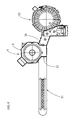
figure 1 illustrates a broken away view of an apparatus for molding containers obtained from parisons, according to the present invention; -
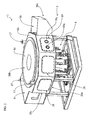
figure 2 illustrates a perspective view of the apparatus offigure 1 ; -
figure 3 illustrates a lateral cutaway view of a portion of the apparatus offigure 1 ; -
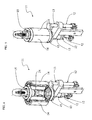
figure 4 illustrates a perspective view of a detail (mould) of the apparatus offigure 1 , in an open position; -
figure 5 illustrates a perspective view of the mould offigure 4 , in a closed position; -
figure 6 illustrates a view from above of the apparatus offigure 1 , connected to a parison treatment station and a receptacle filling station; -
figure 7 illustrates a perspective view of the apparatus offigure 1 , connected to the parison treatment station offigure 6 . - With reference to the
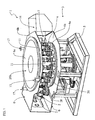
figures, 1 indicates an apparatus formolding containers 2 obtained from parisons of plastic material. Theapparatus 1 provides for the presence of amolding station 3 equipped with amolding machine 4 anddrive components 5 of saidmachine 4. Preferably, themolding machine 4 is a blowing machine. - Said
apparatus 1 comprises anisolation device 6 for themolding machine 4, serving to define a controlled-contamination environment 7 for housing saidmachine 4. Thedrive components 5 are situated outside said controlled-contamination environment 7. In particular, theapparatus 1 comprisestubular bodies 13 disposed partly inside and partly outside the environment 7. Saidtubular bodies 13 define tubular cavities suitable for the passage of thedrive components 5. - Preferably, the
isolation device 6 is composed of amovable portion 6a and a fixedportion 6b. In particular, themovable portion 6a is integral with themolding machine 4. - In the embodiment described and illustrated here, the
molding machine 4 is of the type with arotary carousel 20. In this case, themovable portion 6a is integral with therotary carousel 20. In another embodiment (not illustrated), themolding machine 4 is of the linear type. - Interposed between the
movable portion 6a and the fixedportion 6b there is at least oneseal member 10. More preferably, a plurality ofseal members 10 are interposed between theportions isolation device 6. Preferably, theseal members 10 are of the sliding contact or mechanical labyrinth type (dry seals or wet seals). Saidseal members 10 are situated in alower zone 26a, anupper zone 26b or else in alateral zone 26c of theisolation device 6. - As can be seen in
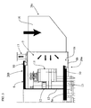
figure 3 , theisolation device 6 is provided with at least aninlet 16 and at least anoutlet 17 for a gaseous fluid. In this manner, the gaseous fluid introduced through theinlet 16 is made to flow through the controlled-contamination environment 7 (the arrows indicate the flow of fluid). Theinlet 16 is fitted with filters (e.g. high efficiency or HEPA filters) for filtering the gaseous fluid before it is introduced into the environment 7. Alternatively, or in addition, filters are fitted to a feed conduit (not illustrated) supplying the gaseous fluid. - Preferably, the
inlet 16 andoutlet 17 are dimensioned according to predefined mutual ratio so as to maintain the fluid at a predetermined pressure. In the embodiment described and illustrated here, theinlet 16, fashioned in thelateral zone 26c of theisolation device 6, has corresponding to it a plurality ofoutlets 17 fashioned in theupper zone 26b. - In the embodiment described and illustrated here, in the
lower zone 26a of theisolation device 6 theseal members 10 are in sliding contact, whereas in theupper zone 26b of the isolation device 6 (in proximity to the outlets 17) theseal members 10 are dry labyrinth seals. - The
apparatus 1 is provided withmoulds 11 fixed to themachine 4. In particular, eachmould 11 is formed by twohalf portions 14, which are relatively movable to each other at least between a closed position and an open position of themould 11. When themould 11 is in the closed position (figure 5 ), the twohalf portions 14 abut so as to define at least a cavity for housing a parison or a moldedcontainer 2. When themould 11 is in the open position (figure 4 ), the twohalf portions 14 are instead positioned apart so as to permit disengagement of the molded container 2 (or the introduction of a new parison). Eachmould 11 is additionally provided with abottom element 25 cooperating with thehalf portions 14 in order to shape a bottom of the receptacle. Eachmould 11 is provided with locking means 15, which are operatively active on themould 11 in the closed position. In particular, the locking means 15 are movable between a locking configuration and a release configuration when themould 11 is in the closed position. - The
drive components 5 comprise rods, connecting rods, cams, rollers, motors, pneumatic actuators, hydraulic actuators and other moving parts. In particular, thedrive components 5 include drivemembers 12 for opening and closing themoulds 11. Preferably, thedrive components 5 also include drive members for raising and lowering themould bottom element 25. - Therefore, the opening and closing of the
moulds 11 is determined by the opening/closing members 12 (comprising, for example, rods associated therewith) housed within respectivetubular bodies 13. The upward or downward movement of thebottom elements 25 is determined by the raising/lowering members (comprising, for example, rods associated therewith) housed within respectivetubular bodies 13. - Preferably, the
isolation device 6 comprises asection 18 for collecting the liquids used for cleaning or sterilizing the controlled-contamination environment 7. In particular, saidcollection section 18 is fashioned in thelower zone 26a of theisolation device 6. It is also envisaged that there will be present exhausters for exhausting the vapours generated by the chemical agents used to clean and sterilize the environment or, if sterilizing agents in a gaseous or vapour state are used, for directly exhausting the substances used for sterilization. - In the
lateral zone 26c of theisolation device 6 there is present at least oneservice section 19, which is provided with one or more points ofaccess 19a with seal-tight protection in order to allow adjustment, maintenance or size change operations to be performed inside the controlled-contamination environment 7. - Preferably, said protected points of
access 19 have seal-tight sleeves complete with work gloves. In the embodiment described and illustrated here (see for examplefigure 2 ), it is envisaged that there will be a plurality ofadjacent service sections 19, each having two protected points ofaccess 19a. - Furthermore, inside the
isolation device 6 there is present at least one section for storing the tools necessary for the adjustment, maintenance and size change operations. Inside theisolation device 6 there is also fashioned at least one section for storing equipment suitable for monitoring and microbiological sampling of the environment 7. - As can be seen in
figure 6 , theapparatus 1 comprises aparison infeed section 23, connectable (so as to ensure a seal-tight barrier against the outside environment) to aparison treatment station 21 in order to receive the treated parisons. Preferably, theparison treatment station 21 is equipped with an oven for heating the parisons before they are submitted to blowing. Theapparatus 1 comprises anoutfeed section 24 for the moldedcontainers 2, connectable (so as to ensure a seal-tight barrier against the outside environment) to astation 22 for filling of thereceptacles 2. - The functioning of the apparatus for molding containers obtained from parisons, according to the present invention, is described below.
- After being heated in the
treatment station 21, the parisons are delivered to themolding station 3 through theinfeed section 23. The controlled-contamination environment 7 of themolding station 3 has previously undergone C.I.P. and S.I.P. treatments to reduce the presence of bacteria, mould or other contaminating substances. The waste liquids collect in thecollection section 18 and are subsequently removed from theisolation device 6, whereas the vapours generated are exhausted. - In the
molding station 3 there is present a first carousel (not illustrated) for transferring the parisons to therotary carousel 20 and asecond carousel 28 for transferring the moldedcontainers 2 from saidrotary carousel 20 to the fillingstation 22. Each parison is inserted between the twohalf portions 14 of the correspondingopen mould 11. During this phase, thehalf portions 14 do not adhere to the parison, which is therefore supported and maintained inside thehalf portions 14 by means of a dedicated component (not illustrated). The twohalf portions 14 are brought progressively closer together so as to close themould 11 and, subsequently, the locking means 15 (consisting, for example, of collars moved by respective rods) go into action. In particular, during the movement of therotary carousel 20, the opening/closing members 12 of eachmould 11 rotate inside the correspondingtubular bodies 13, causing thehalf portions 14 to move closer together. During the final phase of this mutual approaching, thebottom element 25 of themould 11 is made to engage with thehalf portions 14 by virtue of the longitudinal sliding of the raising/lowering member in its correspondingtubular body 13. Once themould 11 is completely closed, the rods of the locking means 15 slide longitudinally inside the correspondingtubular bodies 13, thereby enabling themould 11 to be locked in the closed position. In the end, themould 11 is closed and the parison is housed inside the cavity defined by themould 11. - The parison is then processed, for example by stretching and blowing, in order to obtain the
receptacle 2. - At the end of the blowing phase, during the rotation of the
rotary carousel 20, the rods of the locking means 15 slide longitudinally inside theirtubular bodies 13, causing the respective collars to move apart. The opening/closing members 12 of themould 11 rotate inside thetubular bodies 13, causing thehalf portions 14 to move apart. The raising/lowering member, which slides longitudinally inside its respectivetubular body 13, disengages thebottom element 25 from thehalf portions 14. In the end, themould 11 is open and the moldedcontainer 2 is grasped and extracted from themould 11 by means of the dedicated member, which conveys it to thesecond transfer carousel 28. - The
receptacles 2 thus obtained are delivered to the fillingstation 22 through theoutfeed section 24. - The molding of the
containers 2 takes place in aseptic conditions since the contamination of the environment 7 is kept under control. If maintenance, adjustment or size change operations need to be performed inside the controlled-contamination environment 7, the operator places his arms inside the sleeves of the protected points ofaccess 19a and, using the work gloves provided, takes hold of the tools disposed in the storage section inside theisolation device 6. The operator can also perform microbiological sampling of the environment 7 by taking hold of the suitable monitoring and sampling equipment. - The characteristics of the apparatus for molding containers obtained from parisons according to the present invention emerge clearly from the description provided, as do the advantages thereof.
- In particular, thanks to the fact that the isolation device is applied only to the molding machine (in this case the rotary carousel), the apparatus is compact.
- Moreover, since the drive components are outside the controlled-contamination environment, any build-up of dirt (dust, lubrication oil) on them will not impact the environment in which the rotary carousel is situated, thus enabling the contamination to be easily maintained within the desired level. This disposition of the drive components further enables operators to carry out maintenance and adjustments on such components without entering the controlled-contamination environment. As a result, the risks of contamination are reduced or even eliminated and the operations can be performed more quickly and easily compared to known solutions.
- Furthermore, since maintenance, adjustment and size change operations inside the controlled-contamination environment take place through the protected points of access (with sleeves and work gloves), operators can manually operate inside the environment without coming directly into contact with it. The tools necessary for the operations are moreover already inside the environment, so no persons or tools are ever introduced inside the environment itself. As a result, the risks of contamination are reduced compared to known solutions or even eliminated altogether. The maintaining of environmental contamination within the desired level is also assured by the presence of seal members between the movable portion and fixed portion of the isolation device, as well as the fact that pressure levels are correctly maintained inside the environment.
- The reduction in the risks of contamination is closely tied to the system for driving the movement of the moulds. Thanks to the disposition of the tubular bodies partly inside and partly outside the controlled-contamination environment, the mould opening/closing members can rotate inside said bodies without contaminating the environment. Furthermore, the mould bottom element raising/lowering members can slide longitudinally inside their respective tubular bodies without contaminating the environment. The rods of the locking means (i.e. the collars) likewise slide inside respective tubular bodies without contaminating the environment. Obviously, this configuration of the drive components is made possible precisely by the particular configuration of the moulds themselves.
- In addition, since operators do not directly access the controlled-contamination environment, it is not necessary to open the isolation device to permit the entry thereof; it is sufficient that the operators introduce their arms into the sleeves of the points of access, which they may do at any time. As a result, the time necessary for the various operations is considerably reduced compared to the known art.
- Finally, thanks to the seal-tight connection between the molding station and the parison treatment station and between the molding station and the filling station, it is possible to create an aseptic, controlled-contamination bottling line. Since the molding machine (e.g. blowing machine) is protected by the isolation device, which enables the environmental contamination to be kept under control, it is preferred to sterilize the parisons prior to blowing. This is more convenient and faster than sterilizing the bottles because the parisons have a regular cylindrical shape, are compact and easy to handle and can be easily heated without undergoing deformation.
Claims (15)
- Molding apparatus (1) comprising a molding station (3) equipped with a machine (4) for molding containers (2) obtained from parisons of plastic material and drive components (5) of said machine (4),
characterised in that it comprises an isolation device (6) for the molding machine (4), serving to define a controlled-contamination environment (7) for housing the machine (4), said drive components (5) being situated outside said environment (7). - Apparatus (1) according to claim 1, wherein the isolation device (6) comprises a movable portion (6a) integral with the molding machine (4) and a fixed portion (6b), there being interposed between said portions (6a, 6b) of the isolation device (6) at least one seal member (10).
- Apparatus (1) according to claim 2, wherein a plurality of seal members (10) are interposed between the movable portion (6a) and the fixed portion (6b) of the isolation device (6).
- Apparatus (1) according to any of the preceding claims, comprising tubular bodies (13) disposed partly inside and partly outside said environment (7), said tubular bodies (13) defining tubular cavities suitable for the passage of said drive components (5).
- Apparatus (1) according to claim 4, wherein said drive components (5) include drive members (12) for opening and closing moulds (11) fixed to said machine (4).
- Apparatus (1) according to claim 5, wherein each mould (11) comprises two half portions (14) relatively movable to each other between a closed position and an open position of the mould (11), a bottom element (25) cooperating with the half portions (14) in order to shape the bottom of the receptacle (2) and clamping means (15) for the mould (11), which are movable between a locking configuration and a release configuration when the mould (11) is in the closed position.
- Apparatus (1) according to any of the preceding claims, wherein a gaseous fluid (7) introduced through at least one inlet (16) of the isolation device (6) flows through the controlled-contamination environment and is discharged through at least one outlet (17) of said isolation device (6), said at least one inlet (16) and said at least one outlet (17) of the isolation device (6) being dimensioned according to a predefined mutual ratio so as to maintain the fluid at a predetermined pressure.
- Apparatus (1) according to claim 7, wherein the isolation device (6) is provided with filters fitted to said at least one inlet (16) in order to filter the gaseous fluid.
- Apparatus (1) according to claims 2 to 8, wherein said at least one seal member (10) is of the sliding contact or mechanical labyrinth type.
- Apparatus (1) according to any of the preceding claims, wherein the isolation device (6) is provided with a section (18) for collecting the liquids used for cleaning and sterilizing the controlled-contamination environment (7).
- Apparatus (1) according to any of the preceding claims, wherein the isolation device (6) is provided with at least one service section (19) having one or more points of access (19a) with seal-tight protection to enable adjustment, maintenance or size change operations to be performed inside the controlled-contamination environment (7).
- Apparatus (1) according to any of the preceding claims, wherein the isolation device (6) is provided with at least one storage section to house the tools necessary for the adjustment, maintenance or size change operations.
- Apparatus (1) according to any of the preceding claims, wherein the isolation device (6) is provided with at least one storage section to house equipment suitable for monitoring and microbiological sampling of said environment (7).
- Apparatus (1) according to any of the preceding claims, wherein said molding machine (4) is of the type with a rotary carousel (20).
- Apparatus (1) according to any of the preceding claims, further comprising a parison infeed section (23) and an outfeed section (24) for the molded containers (2), said infeed section (23) being connectable to a station (21) for treating said parisons so as to receive the treated parisons, said outfeed section (24) being connectable to a station (22) for filling said receptacles (2) in order to transfer thereto the molded containers (2).
Priority Applications (6)
| Application Number | Priority Date | Filing Date | Title |
|---|---|---|---|
| AT09425161T ATE539871T1 (en) | 2009-04-28 | 2009-04-28 | DEVICE FOR PRODUCING CONTAINERS FROM PREFORMS |
| EP09425161.8A EP2246176B2 (en) | 2009-04-28 | 2009-04-28 | Apparatus for molding containers obtained from parisons |
| RU2010116715/05A RU2445205C2 (en) | 2009-04-28 | 2010-04-27 | Device for moulding vessels from billets |
| US12/768,410 US8197245B2 (en) | 2009-04-28 | 2010-04-27 | Apparatus for molding containers obtained from parisons |
| JP2010103764A JP5495318B2 (en) | 2009-04-28 | 2010-04-28 | Equipment for molding containers obtained from parisons |
| CN201010169107.0A CN101875237B (en) | 2009-04-28 | 2010-04-28 | Apparatus for molding containers obtained from parisons |
Applications Claiming Priority (1)
| Application Number | Priority Date | Filing Date | Title |
|---|---|---|---|
| EP09425161.8A EP2246176B2 (en) | 2009-04-28 | 2009-04-28 | Apparatus for molding containers obtained from parisons |
Publications (3)
| Publication Number | Publication Date |
|---|---|
| EP2246176A1 true EP2246176A1 (en) | 2010-11-03 |
| EP2246176B1 EP2246176B1 (en) | 2012-01-04 |
| EP2246176B2 EP2246176B2 (en) | 2019-12-04 |
Family
ID=41077697
Family Applications (1)
| Application Number | Title | Priority Date | Filing Date |
|---|---|---|---|
| EP09425161.8A Active EP2246176B2 (en) | 2009-04-28 | 2009-04-28 | Apparatus for molding containers obtained from parisons |
Country Status (6)
| Country | Link |
|---|---|
| US (1) | US8197245B2 (en) |
| EP (1) | EP2246176B2 (en) |
| JP (1) | JP5495318B2 (en) |
| CN (1) | CN101875237B (en) |
| AT (1) | ATE539871T1 (en) |
| RU (1) | RU2445205C2 (en) |
Cited By (25)
| Publication number | Priority date | Publication date | Assignee | Title |
|---|---|---|---|---|
| EP2388129A1 (en) * | 2010-05-20 | 2011-11-23 | Krones AG | Device for reforming plastic pre-forms with a sterile area |
| EP2431058A1 (en) * | 2010-09-20 | 2012-03-21 | Krones AG | Aseptic sterilisation unit for clean room on blowing wheel |
| ITPR20100095A1 (en) * | 2010-12-23 | 2012-06-24 | Gea Procomac Spa | STERILIZATION SYSTEM OF FORMING MOLDS AND PROCEDURE TO STERILIZE AND INTRODUCE SUCH MOLDS IN AN ASEPTIC BOTTLE LINE |
| EP2495090A1 (en) * | 2011-03-04 | 2012-09-05 | Krones AG | Blow moulding machine with sterile area and media supply in the sterile area |
| EP2511070A1 (en) * | 2011-04-13 | 2012-10-17 | Krones AG | Device and method for moulding plastic preforms into plastic containers with coupled pivoting and locking movements |
| DE102011052574A1 (en) * | 2011-08-11 | 2013-02-14 | Krones Aktiengesellschaft | Blow molding machine, method for exchanging blowing station components and beverage bottling plant and / or beverage container manufacturing plant |
| WO2014140949A1 (en) | 2013-03-11 | 2014-09-18 | Gea Procomac S.P.A. | A treatment apparatus, using a sterilizing substance, for closures for containers |
| WO2014140948A1 (en) | 2013-03-11 | 2014-09-18 | Gea Procomac S.P.A. | A treatment apparatus, using a sterilizing substance, for closures for containers |
| DE102011122853B4 (en) * | 2011-08-11 | 2015-01-22 | Krones Aktiengesellschaft | Blow molding machine, method for exchanging blowing station components and beverage bottling plant and / or beverage container manufacturing plant |
| EP2661351B1 (en) | 2011-01-04 | 2015-04-22 | KHS Corpoplast GmbH | Method and device for blow-molding sterilized containers |
| WO2016012885A1 (en) | 2014-07-21 | 2016-01-28 | Gea Procomac S.P.A. | Method for moulding and sterilizing a container made of plastic material, device for moulding and sterilizing a container made of plastic material and moulding and sterilizing machine |
| WO2016012883A1 (en) | 2014-07-21 | 2016-01-28 | Gea Procomac S.P.A. | Moulding device for moulding a container starting with a parison in plastic material and moulding machine comprising this device |
| WO2016012884A1 (en) | 2014-07-21 | 2016-01-28 | Gea Procomac S.P.A. | Moulding device for moulding a container starting with a parison in plastic material, moulding method and moulding machine |
| WO2016088003A1 (en) | 2014-12-01 | 2016-06-09 | Gea Procomac S.P.A. | A production apparatus of sterile receptacles, a bottling plant comprising the apparatus and a production method of a sterile receptacle |
| WO2016088004A1 (en) | 2014-12-01 | 2016-06-09 | Gea Procomac S.P.A. | A production apparatus of sterile receptacles and a bottling plant comprising the apparatus |
| WO2016108124A1 (en) | 2014-12-30 | 2016-07-07 | Gea Procomac S.P.A. | Process station for a parison or a container made of thermoplastic material, apparatus for processing parisons or containers, production and packaging line for producing and packaging the containers and method for producing and packaging containers |
| WO2016108125A1 (en) | 2014-12-30 | 2016-07-07 | Gea Procomac S.P.A. | Apparatus and method for filling containers |
| EP2709819B1 (en) | 2011-05-19 | 2017-11-15 | KHS GmbH | Method and device for cleaning and/or disinfecting a device for producing containers filled with a liquid filling material |
| EP3513944A1 (en) | 2018-01-23 | 2019-07-24 | Gea Procomac S.p.A. | Bottling apparatus in aseptic conditions for containers made of thermoplastic material |
| WO2019145766A1 (en) | 2018-01-23 | 2019-08-01 | Gea Procomac S.P.A. | Apparatus and process for aseptic molding of a container starting from a parison made of a thermoplastic material |
| WO2020025224A1 (en) | 2018-07-31 | 2020-02-06 | Gea Procomac S.P.A. | Apparatus and process for decontaminating the mouth of a parison or container in thermoplastic material |
| IT201900007220A1 (en) | 2019-05-24 | 2020-11-24 | Gea Procomac Spa | MOLD FOR FORMING A CONTAINER STARTING FROM A PREFORM IN THERMOPLASTIC MATERIAL AND RELATED FORMING PROCESS |
| IT201900010134A1 (en) * | 2019-06-26 | 2020-12-26 | Sidel Participations Sas | RECIPIENT TREATMENT PLANT SUITABLE TO CONTAIN A VERSABLE PRODUCT |
| EP3888884A1 (en) | 2020-03-30 | 2021-10-06 | Gea Procomac S.p.A. | Apparatus and process for aseptically forming containers starting from parisons made of a thermoplastic material |
| IT202000009112A1 (en) | 2020-04-27 | 2021-10-27 | Gea Procomac Spa | ASEPTIC FORMING STATION OF A CONTAINER STARTING FROM A PREFORM MADE OF THERMOPLASTIC MATERIAL, ASEPTIC FORMING APPARATUS AND PROCESS |
Families Citing this family (8)
| Publication number | Priority date | Publication date | Assignee | Title |
|---|---|---|---|---|
| DE102009040978A1 (en) * | 2009-09-11 | 2011-03-17 | Krones Ag | Magazine device for blow molding with cleaning device |
| DE102011013126A1 (en) * | 2011-03-04 | 2012-09-06 | Krones Aktiengesellschaft | Blowing machine with blow mold locking in the clean room |
| DE102011101256A1 (en) * | 2011-05-11 | 2012-11-15 | Krones Aktiengesellschaft | Aseptic blow molding machine with sterile air discharge |
| DE102011104316A1 (en) * | 2011-06-03 | 2012-12-06 | Krones Aktiengesellschaft | Device and system for insert blowing plastic preforms and use of a ceramic component |
| DE202013103477U1 (en) * | 2013-08-02 | 2014-11-04 | Krones Ag | Container treatment machine with a gutter |
| US9050749B1 (en) * | 2014-01-10 | 2015-06-09 | Chumpower Machinery Corp. | Blow molding device for a rotary bottle blowing machine |
| EP3520992B1 (en) | 2016-09-28 | 2024-04-03 | Dai Nippon Printing Co., Ltd. | Device and method for heating preforms, aseptic blow moulding machine, and aseptic blow moulding method |
| IT202000009685A1 (en) * | 2020-05-04 | 2021-11-04 | Smi Spa | MACHINE FOR PACKAGING LIQUIDS OR SEMI-SOLID PRODUCTS IN CONTAINERS |
Citations (6)
| Publication number | Priority date | Publication date | Assignee | Title |
|---|---|---|---|---|
| EP0741080A1 (en) | 1995-05-01 | 1996-11-06 | Ashland Inc. | Integrated container molding and filling facility |
| US5759218A (en) | 1996-10-24 | 1998-06-02 | Allergan | Point of fill air system |
| EP1445011A1 (en) * | 2003-02-10 | 2004-08-11 | Staubfresser GmbH | Air purification fan |
| FR2882341A1 (en) * | 2005-02-23 | 2006-08-25 | Serac Group Soc Par Actions Si | INSTALLATION OF ASEPTIC PACKAGING WITH ASEPTIC BUFFER ZONES |
| US7393373B1 (en) * | 2004-06-14 | 2008-07-01 | H.K. Plastics Engineering, Inc. | Portable clean molding apparatus and method of use |
| DE102007017938A1 (en) * | 2007-04-13 | 2008-10-16 | Khs Ag | Container manufacturing apparatus and mold production method |
Family Cites Families (17)
| Publication number | Priority date | Publication date | Assignee | Title |
|---|---|---|---|---|
| US4208852A (en) * | 1974-11-08 | 1980-06-24 | Pont-A-Mousson S.A. | Process for the aseptic packing of products and machine employing said process |
| DE3729451C1 (en) * | 1987-09-03 | 1988-06-16 | Berstorff Gmbh Masch Hermann | Device for exact and quick opening and closing of the two mold halves of a blow mold |
| NL9001504A (en) * | 1990-07-02 | 1992-02-03 | Stork Amsterdam | METHOD AND APPARATUS FOR MANUFACTURING PLASTIC CONTAINERS, SUCH AS BOTTLES, WITH A MULTILAYER WALL. |
| IT1279846B1 (en) † | 1995-08-11 | 1997-12-18 | Rossi & Catelli Spa | CONTINUOUS ASEPTIC BOTTLING SYSTEM |
| DE29713155U1 (en) † | 1997-07-24 | 1998-09-10 | Kronseder Maschf Krones | Rotary filler |
| DE19821280A1 (en) † | 1998-05-13 | 1999-11-18 | Groninger & Co Gmbh | Locking device between a non-sterile area and a sterile area |
| US6447281B1 (en) † | 1998-09-11 | 2002-09-10 | Sidel, Inc. | Blow mold shell and shell holder assembly for blow-molding machine |
| JP4074400B2 (en) * | 1999-01-13 | 2008-04-09 | 日精エー・エス・ビー機械株式会社 | Air conditioner for injection stretch blow molding machine |
| DE10140906B4 (en) * | 2001-08-21 | 2004-02-12 | Krones Ag | Method and device for blowing out plastic preforms |
| DE10323335A1 (en) * | 2003-05-23 | 2004-12-16 | Hansen, Bernd, Dipl.-Ing. | Fabrication |
| DE102004045405A1 (en) † | 2004-09-18 | 2006-04-13 | Sig Technology Ltd. | Device for blow molding containers |
| DE102006053193A1 (en) * | 2006-11-09 | 2008-05-15 | Krones Ag | Apparatus and method for producing plastic containers |
| EP2116353B1 (en) * | 2007-02-26 | 2014-09-24 | Toyo Seikan Kaisha, Ltd. | Blow molding machine with air conditioning |
| FR2914875B1 (en) † | 2007-04-13 | 2009-07-10 | Sidel Participations | MOLDING DEVICE FOR THE MANUFACTURE OF THERMOPLASTIC CONTAINERS BY BLOWING OR STRETCH BLOWING. |
| FR2915127B1 (en) † | 2007-04-20 | 2012-10-12 | Sidel Participations | INSTALLATION FOR THE MANUFACTURE OF CONTAINERS COMPRISING A PROTECTION ENCLOSURE EQUIPPED WITH A SYSTEM OF AIR FILTER INSUFFLATION |
| DE102008017768A1 (en) † | 2008-04-08 | 2009-10-15 | Groninger & Co. Gmbh | Locking device, particularly for use in pharmaceutical industry, has boundary, which is provided between unsterile area and sterile area, through which movable driving element extends into sterile area |
| DE102008038141A1 (en) * | 2008-08-18 | 2010-02-25 | Krones Ag | Device for forming plastic preforms with sterile space |
-
2009
- 2009-04-28 EP EP09425161.8A patent/EP2246176B2/en active Active
- 2009-04-28 AT AT09425161T patent/ATE539871T1/en active
-
2010
- 2010-04-27 RU RU2010116715/05A patent/RU2445205C2/en not_active IP Right Cessation
- 2010-04-27 US US12/768,410 patent/US8197245B2/en active Active
- 2010-04-28 JP JP2010103764A patent/JP5495318B2/en active Active
- 2010-04-28 CN CN201010169107.0A patent/CN101875237B/en active Active
Patent Citations (6)
| Publication number | Priority date | Publication date | Assignee | Title |
|---|---|---|---|---|
| EP0741080A1 (en) | 1995-05-01 | 1996-11-06 | Ashland Inc. | Integrated container molding and filling facility |
| US5759218A (en) | 1996-10-24 | 1998-06-02 | Allergan | Point of fill air system |
| EP1445011A1 (en) * | 2003-02-10 | 2004-08-11 | Staubfresser GmbH | Air purification fan |
| US7393373B1 (en) * | 2004-06-14 | 2008-07-01 | H.K. Plastics Engineering, Inc. | Portable clean molding apparatus and method of use |
| FR2882341A1 (en) * | 2005-02-23 | 2006-08-25 | Serac Group Soc Par Actions Si | INSTALLATION OF ASEPTIC PACKAGING WITH ASEPTIC BUFFER ZONES |
| DE102007017938A1 (en) * | 2007-04-13 | 2008-10-16 | Khs Ag | Container manufacturing apparatus and mold production method |
Cited By (44)
| Publication number | Priority date | Publication date | Assignee | Title |
|---|---|---|---|---|
| EP2388129A1 (en) * | 2010-05-20 | 2011-11-23 | Krones AG | Device for reforming plastic pre-forms with a sterile area |
| DE102010045832B4 (en) | 2010-09-20 | 2023-10-19 | Krones Aktiengesellschaft | Aseptic sterilization unit for clean rooms on a blowing wheel |
| EP2431058A1 (en) * | 2010-09-20 | 2012-03-21 | Krones AG | Aseptic sterilisation unit for clean room on blowing wheel |
| DE102010045832A1 (en) * | 2010-09-20 | 2012-03-22 | Krones Aktiengesellschaft | Aseptic sterilization unit for clean room on blowing wheel |
| US8920745B2 (en) | 2010-09-20 | 2014-12-30 | Krones Ag | Aseptic sterilization unit for clean room on blowing wheel |
| EP2468478A1 (en) | 2010-12-23 | 2012-06-27 | Gea Procomac S.p.A. | Process for sterilising and introducing forming moulds into an aseptic bottling line |
| ITPR20100095A1 (en) * | 2010-12-23 | 2012-06-24 | Gea Procomac Spa | STERILIZATION SYSTEM OF FORMING MOLDS AND PROCEDURE TO STERILIZE AND INTRODUCE SUCH MOLDS IN AN ASEPTIC BOTTLE LINE |
| EP2661351B1 (en) | 2011-01-04 | 2015-04-22 | KHS Corpoplast GmbH | Method and device for blow-molding sterilized containers |
| US8696339B2 (en) | 2011-03-04 | 2014-04-15 | Krones Ag | Blow moulding machine with sterile chamber and media feed in the sterile chamber |
| EP2495090A1 (en) * | 2011-03-04 | 2012-09-05 | Krones AG | Blow moulding machine with sterile area and media supply in the sterile area |
| EP2511070A1 (en) * | 2011-04-13 | 2012-10-17 | Krones AG | Device and method for moulding plastic preforms into plastic containers with coupled pivoting and locking movements |
| US20120261865A1 (en) * | 2011-04-13 | 2012-10-18 | Krones Ag | Apparatus and Method for Transforming Plastic Preforms into Plastic Containers, with Coupled Pivoting and Locking Movements |
| US9061459B2 (en) * | 2011-04-13 | 2015-06-23 | Krones Ag | Apparatus and method for transforming plastic preforms into plastic containers, with coupled pivoting and locking movements |
| EP2709819B1 (en) | 2011-05-19 | 2017-11-15 | KHS GmbH | Method and device for cleaning and/or disinfecting a device for producing containers filled with a liquid filling material |
| DE102011052574A1 (en) * | 2011-08-11 | 2013-02-14 | Krones Aktiengesellschaft | Blow molding machine, method for exchanging blowing station components and beverage bottling plant and / or beverage container manufacturing plant |
| US8770957B2 (en) | 2011-08-11 | 2014-07-08 | Krones Ag | Blow moulding machine, method of exchanging blow moulding station components and beverage filling plant and/or beverage container production plant |
| DE102011122853B4 (en) * | 2011-08-11 | 2015-01-22 | Krones Aktiengesellschaft | Blow molding machine, method for exchanging blowing station components and beverage bottling plant and / or beverage container manufacturing plant |
| WO2014140948A1 (en) | 2013-03-11 | 2014-09-18 | Gea Procomac S.P.A. | A treatment apparatus, using a sterilizing substance, for closures for containers |
| US9522204B2 (en) | 2013-03-11 | 2016-12-20 | Gea Procomac S.P.A. | Treatment apparatus, using a sterilizing substance, for closures for containers |
| WO2014140949A1 (en) | 2013-03-11 | 2014-09-18 | Gea Procomac S.P.A. | A treatment apparatus, using a sterilizing substance, for closures for containers |
| US10029900B2 (en) | 2013-03-11 | 2018-07-24 | Gea Procomac S.P.A. | Treatment apparatus, using a sterilizing substance, for closures for containers |
| WO2016012883A1 (en) | 2014-07-21 | 2016-01-28 | Gea Procomac S.P.A. | Moulding device for moulding a container starting with a parison in plastic material and moulding machine comprising this device |
| WO2016012884A1 (en) | 2014-07-21 | 2016-01-28 | Gea Procomac S.P.A. | Moulding device for moulding a container starting with a parison in plastic material, moulding method and moulding machine |
| WO2016012885A1 (en) | 2014-07-21 | 2016-01-28 | Gea Procomac S.P.A. | Method for moulding and sterilizing a container made of plastic material, device for moulding and sterilizing a container made of plastic material and moulding and sterilizing machine |
| WO2016088003A1 (en) | 2014-12-01 | 2016-06-09 | Gea Procomac S.P.A. | A production apparatus of sterile receptacles, a bottling plant comprising the apparatus and a production method of a sterile receptacle |
| WO2016088004A1 (en) | 2014-12-01 | 2016-06-09 | Gea Procomac S.P.A. | A production apparatus of sterile receptacles and a bottling plant comprising the apparatus |
| US10343325B2 (en) | 2014-12-01 | 2019-07-09 | Gea Procomac S.P.A. | Production apparatus of sterile receptacles, a bottling plant comprising the apparatus and a production method of a sterile receptacle |
| WO2016108124A1 (en) | 2014-12-30 | 2016-07-07 | Gea Procomac S.P.A. | Process station for a parison or a container made of thermoplastic material, apparatus for processing parisons or containers, production and packaging line for producing and packaging the containers and method for producing and packaging containers |
| US10800088B2 (en) | 2014-12-30 | 2020-10-13 | Gea Procomac S.P.A. | Process station for a parison or a container made of thermoplastic material, apparatus for processing parisons or containers, production and packaging line for producing and packaging the containers and method for producing and packaging containers |
| WO2016108125A1 (en) | 2014-12-30 | 2016-07-07 | Gea Procomac S.P.A. | Apparatus and method for filling containers |
| US10287152B2 (en) | 2014-12-30 | 2019-05-14 | Gea Procomac S.P.A. | Apparatus and method for filling containers |
| US10933574B2 (en) | 2018-01-23 | 2021-03-02 | Gea Procomac S.P.A. | Bottling apparatus in aseptic conditions for containers made of thermoplastic material |
| WO2019145766A1 (en) | 2018-01-23 | 2019-08-01 | Gea Procomac S.P.A. | Apparatus and process for aseptic molding of a container starting from a parison made of a thermoplastic material |
| US11014282B2 (en) | 2018-01-23 | 2021-05-25 | Gea Procomac S.P.A. | Apparatus and process for aseptic molding of a container starting from a parison made of a thermoplastic material |
| EP3513944A1 (en) | 2018-01-23 | 2019-07-24 | Gea Procomac S.p.A. | Bottling apparatus in aseptic conditions for containers made of thermoplastic material |
| WO2020025224A1 (en) | 2018-07-31 | 2020-02-06 | Gea Procomac S.P.A. | Apparatus and process for decontaminating the mouth of a parison or container in thermoplastic material |
| IT201900007220A1 (en) | 2019-05-24 | 2020-11-24 | Gea Procomac Spa | MOLD FOR FORMING A CONTAINER STARTING FROM A PREFORM IN THERMOPLASTIC MATERIAL AND RELATED FORMING PROCESS |
| IT201900010134A1 (en) * | 2019-06-26 | 2020-12-26 | Sidel Participations Sas | RECIPIENT TREATMENT PLANT SUITABLE TO CONTAIN A VERSABLE PRODUCT |
| EP3757025A1 (en) * | 2019-06-26 | 2020-12-30 | Sidel Participations | A plant for treating receptacles adapted to contain a pourable product |
| EP3888884A1 (en) | 2020-03-30 | 2021-10-06 | Gea Procomac S.p.A. | Apparatus and process for aseptically forming containers starting from parisons made of a thermoplastic material |
| EP3888884B1 (en) | 2020-03-30 | 2022-05-04 | Gea Procomac S.p.A. | Apparatus and process for aseptically forming containers starting from parisons made of a thermoplastic material |
| US11613064B2 (en) | 2020-03-30 | 2023-03-28 | Gea Procomac S.P.A. | Apparatus and process for aseptically forming containers starting from parisons made of a thermoplastic material |
| IT202000009112A1 (en) | 2020-04-27 | 2021-10-27 | Gea Procomac Spa | ASEPTIC FORMING STATION OF A CONTAINER STARTING FROM A PREFORM MADE OF THERMOPLASTIC MATERIAL, ASEPTIC FORMING APPARATUS AND PROCESS |
| EP3904046A1 (en) | 2020-04-27 | 2021-11-03 | Gea Procomac S.p.A. | An aseptic forming station for forming a container starting from a preform made of thermoplastic material, an aseptic forming apparatus and process |
Also Published As
| Publication number | Publication date |
|---|---|
| EP2246176B2 (en) | 2019-12-04 |
| US20100272844A1 (en) | 2010-10-28 |
| ATE539871T1 (en) | 2012-01-15 |
| EP2246176B1 (en) | 2012-01-04 |
| RU2010116715A (en) | 2011-11-27 |
| US8197245B2 (en) | 2012-06-12 |
| RU2445205C2 (en) | 2012-03-20 |
| CN101875237A (en) | 2010-11-03 |
| JP2010264753A (en) | 2010-11-25 |
| CN101875237B (en) | 2014-05-07 |
| JP5495318B2 (en) | 2014-05-21 |
Similar Documents
| Publication | Publication Date | Title |
|---|---|---|
| US8197245B2 (en) | Apparatus for molding containers obtained from parisons | |
| JP5969849B2 (en) | Blow molding apparatus, method for replacing components of a blow molding station, and beverage filling plant and / or beverage container manufacturing plant | |
| EP2279850B1 (en) | Method and plant for producing, filling and closing containers | |
| EP2388129B1 (en) | Device for reforming plastic pre-forms with a sterile area | |
| EP2015996B2 (en) | Packing machine, in particular encompassing a deep drawing machine | |
| US20140196415A1 (en) | Method and device for cleaning and/or disinfecting a device for producing containers filled with a liquid filling material | |
| CN102173320B (en) | Apparatus for transferring and moving elements of a working machine | |
| DE102011122853A1 (en) | Blowing machine for transforming plastic preform to plastic container, used in beverage container treatment plant, has clean chamber whose preparation entrance has sterile space arranged environment-side upstream with blowing station | |
| EP1357081B1 (en) | Aseptic filling machine | |
| EP2007633B1 (en) | System and method for transferring and moving elements of an automatic packaging machine | |
| JP2014516832A (en) | An exhaust circuit from a parison, an air supply / exhaust system from the parison, and an aseptic molding method using the circuit and system. | |
| JP6026183B2 (en) | Blow molding apparatus having a detachable blow molding station | |
| EP2495090B1 (en) | Blow moulding machine with sterile area and media supply in the sterile area | |
| CN107107449A (en) | The method of the parison or the processing station of container, the equipment of processing parison or container, production and the production of packing container and baling line and production and the packing container that are made up of thermoplastic | |
| CA2143575C (en) | Device for sterile filling of containers | |
| EP3828090A2 (en) | Apparatus for filling containers in a sterile environment | |
| CN107823674A (en) | Medical oncology sterilizer | |
| CN108472397A (en) | The sterilizing methods and container manufacturing facility of the drawing components of container device for molding |
Legal Events
| Date | Code | Title | Description |
|---|---|---|---|
| PUAI | Public reference made under article 153(3) epc to a published international application that has entered the european phase |
Free format text: ORIGINAL CODE: 0009012 |
|
| 17P | Request for examination filed |
Effective date: 20100506 |
|
| AK | Designated contracting states |
Kind code of ref document: A1 Designated state(s): AT BE BG CH CY CZ DE DK EE ES FI FR GB GR HR HU IE IS IT LI LT LU LV MC MK MT NL NO PL PT RO SE SI SK TR |
|
| AX | Request for extension of the european patent |
Extension state: AL BA RS |
|
| GRAP | Despatch of communication of intention to grant a patent |
Free format text: ORIGINAL CODE: EPIDOSNIGR1 |
|
| RIC1 | Information provided on ipc code assigned before grant |
Ipc: B29C 49/46 20060101AFI20110719BHEP Ipc: B29C 49/36 20060101ALI20110719BHEP Ipc: B65B 55/02 20060101ALI20110719BHEP |
|
| GRAJ | Information related to disapproval of communication of intention to grant by the applicant or resumption of examination proceedings by the epo deleted |
Free format text: ORIGINAL CODE: EPIDOSDIGR1 |
|
| GRAP | Despatch of communication of intention to grant a patent |
Free format text: ORIGINAL CODE: EPIDOSNIGR1 |
|
| GRAS | Grant fee paid |
Free format text: ORIGINAL CODE: EPIDOSNIGR3 |
|
| GRAA | (expected) grant |
Free format text: ORIGINAL CODE: 0009210 |
|
| AK | Designated contracting states |
Kind code of ref document: B1 Designated state(s): AT BE BG CH CY CZ DE DK EE ES FI FR GB GR HR HU IE IS IT LI LT LU LV MC MK MT NL NO PL PT RO SE SI SK TR |
|
| REG | Reference to a national code |
Ref country code: GB Ref legal event code: FG4D |
|
| REG | Reference to a national code |
Ref country code: CH Ref legal event code: EP |
|
| REG | Reference to a national code |
Ref country code: AT Ref legal event code: REF Ref document number: 539871 Country of ref document: AT Kind code of ref document: T Effective date: 20120115 |
|
| REG | Reference to a national code |
Ref country code: IE Ref legal event code: FG4D |
|
| REG | Reference to a national code |
Ref country code: DE Ref legal event code: R096 Ref document number: 602009004522 Country of ref document: DE Effective date: 20120308 |
|
| REG | Reference to a national code |
Ref country code: NL Ref legal event code: VDEP Effective date: 20120104 |
|
| PG25 | Lapsed in a contracting state [announced via postgrant information from national office to epo] |
Ref country code: SI Free format text: LAPSE BECAUSE OF FAILURE TO SUBMIT A TRANSLATION OF THE DESCRIPTION OR TO PAY THE FEE WITHIN THE PRESCRIBED TIME-LIMIT Effective date: 20120104 |
|
| LTIE | Lt: invalidation of european patent or patent extension |
Effective date: 20120104 |
|
| PG25 | Lapsed in a contracting state [announced via postgrant information from national office to epo] |
Ref country code: NL Free format text: LAPSE BECAUSE OF FAILURE TO SUBMIT A TRANSLATION OF THE DESCRIPTION OR TO PAY THE FEE WITHIN THE PRESCRIBED TIME-LIMIT Effective date: 20120104 Ref country code: HR Free format text: LAPSE BECAUSE OF FAILURE TO SUBMIT A TRANSLATION OF THE DESCRIPTION OR TO PAY THE FEE WITHIN THE PRESCRIBED TIME-LIMIT Effective date: 20120104 Ref country code: LT Free format text: LAPSE BECAUSE OF FAILURE TO SUBMIT A TRANSLATION OF THE DESCRIPTION OR TO PAY THE FEE WITHIN THE PRESCRIBED TIME-LIMIT Effective date: 20120104 Ref country code: NO Free format text: LAPSE BECAUSE OF FAILURE TO SUBMIT A TRANSLATION OF THE DESCRIPTION OR TO PAY THE FEE WITHIN THE PRESCRIBED TIME-LIMIT Effective date: 20120404 Ref country code: BG Free format text: LAPSE BECAUSE OF FAILURE TO SUBMIT A TRANSLATION OF THE DESCRIPTION OR TO PAY THE FEE WITHIN THE PRESCRIBED TIME-LIMIT Effective date: 20120404 Ref country code: BE Free format text: LAPSE BECAUSE OF FAILURE TO SUBMIT A TRANSLATION OF THE DESCRIPTION OR TO PAY THE FEE WITHIN THE PRESCRIBED TIME-LIMIT Effective date: 20120104 Ref country code: IS Free format text: LAPSE BECAUSE OF FAILURE TO SUBMIT A TRANSLATION OF THE DESCRIPTION OR TO PAY THE FEE WITHIN THE PRESCRIBED TIME-LIMIT Effective date: 20120504 |
|
| PG25 | Lapsed in a contracting state [announced via postgrant information from national office to epo] |
Ref country code: FI Free format text: LAPSE BECAUSE OF FAILURE TO SUBMIT A TRANSLATION OF THE DESCRIPTION OR TO PAY THE FEE WITHIN THE PRESCRIBED TIME-LIMIT Effective date: 20120104 Ref country code: PT Free format text: LAPSE BECAUSE OF FAILURE TO SUBMIT A TRANSLATION OF THE DESCRIPTION OR TO PAY THE FEE WITHIN THE PRESCRIBED TIME-LIMIT Effective date: 20120504 Ref country code: LV Free format text: LAPSE BECAUSE OF FAILURE TO SUBMIT A TRANSLATION OF THE DESCRIPTION OR TO PAY THE FEE WITHIN THE PRESCRIBED TIME-LIMIT Effective date: 20120104 Ref country code: GR Free format text: LAPSE BECAUSE OF FAILURE TO SUBMIT A TRANSLATION OF THE DESCRIPTION OR TO PAY THE FEE WITHIN THE PRESCRIBED TIME-LIMIT Effective date: 20120405 Ref country code: PL Free format text: LAPSE BECAUSE OF FAILURE TO SUBMIT A TRANSLATION OF THE DESCRIPTION OR TO PAY THE FEE WITHIN THE PRESCRIBED TIME-LIMIT Effective date: 20120104 |
|
| PG25 | Lapsed in a contracting state [announced via postgrant information from national office to epo] |
Ref country code: CY Free format text: LAPSE BECAUSE OF FAILURE TO SUBMIT A TRANSLATION OF THE DESCRIPTION OR TO PAY THE FEE WITHIN THE PRESCRIBED TIME-LIMIT Effective date: 20120104 |
|
| PLBI | Opposition filed |
Free format text: ORIGINAL CODE: 0009260 |
|
| PG25 | Lapsed in a contracting state [announced via postgrant information from national office to epo] |
Ref country code: RO Free format text: LAPSE BECAUSE OF FAILURE TO SUBMIT A TRANSLATION OF THE DESCRIPTION OR TO PAY THE FEE WITHIN THE PRESCRIBED TIME-LIMIT Effective date: 20120104 Ref country code: DK Free format text: LAPSE BECAUSE OF FAILURE TO SUBMIT A TRANSLATION OF THE DESCRIPTION OR TO PAY THE FEE WITHIN THE PRESCRIBED TIME-LIMIT Effective date: 20120104 Ref country code: EE Free format text: LAPSE BECAUSE OF FAILURE TO SUBMIT A TRANSLATION OF THE DESCRIPTION OR TO PAY THE FEE WITHIN THE PRESCRIBED TIME-LIMIT Effective date: 20120104 Ref country code: SE Free format text: LAPSE BECAUSE OF FAILURE TO SUBMIT A TRANSLATION OF THE DESCRIPTION OR TO PAY THE FEE WITHIN THE PRESCRIBED TIME-LIMIT Effective date: 20120104 Ref country code: CZ Free format text: LAPSE BECAUSE OF FAILURE TO SUBMIT A TRANSLATION OF THE DESCRIPTION OR TO PAY THE FEE WITHIN THE PRESCRIBED TIME-LIMIT Effective date: 20120104 |
|
| PLAX | Notice of opposition and request to file observation + time limit sent |
Free format text: ORIGINAL CODE: EPIDOSNOBS2 |
|
| 26 | Opposition filed |
Opponent name: KHS CORPOPLAST GMBH Effective date: 20121004 |
|
| PG25 | Lapsed in a contracting state [announced via postgrant information from national office to epo] |
Ref country code: MC Free format text: LAPSE BECAUSE OF NON-PAYMENT OF DUE FEES Effective date: 20120430 Ref country code: SK Free format text: LAPSE BECAUSE OF FAILURE TO SUBMIT A TRANSLATION OF THE DESCRIPTION OR TO PAY THE FEE WITHIN THE PRESCRIBED TIME-LIMIT Effective date: 20120104 |
|
| REG | Reference to a national code |
Ref country code: DE Ref legal event code: R026 Ref document number: 602009004522 Country of ref document: DE Effective date: 20121004 |
|
| PLAF | Information modified related to communication of a notice of opposition and request to file observations + time limit |
Free format text: ORIGINAL CODE: EPIDOSCOBS2 |
|
| PG25 | Lapsed in a contracting state [announced via postgrant information from national office to epo] |
Ref country code: MK Free format text: LAPSE BECAUSE OF FAILURE TO SUBMIT A TRANSLATION OF THE DESCRIPTION OR TO PAY THE FEE WITHIN THE PRESCRIBED TIME-LIMIT Effective date: 20120104 |
|
| PG25 | Lapsed in a contracting state [announced via postgrant information from national office to epo] |
Ref country code: IE Free format text: LAPSE BECAUSE OF NON-PAYMENT OF DUE FEES Effective date: 20120428 Ref country code: ES Free format text: LAPSE BECAUSE OF FAILURE TO SUBMIT A TRANSLATION OF THE DESCRIPTION OR TO PAY THE FEE WITHIN THE PRESCRIBED TIME-LIMIT Effective date: 20120415 |
|
| PLBB | Reply of patent proprietor to notice(s) of opposition received |
Free format text: ORIGINAL CODE: EPIDOSNOBS3 |
|
| PLAB | Opposition data, opponent's data or that of the opponent's representative modified |
Free format text: ORIGINAL CODE: 0009299OPPO |
|
| R26 | Opposition filed (corrected) |
Opponent name: KHS CORPOPLAST GMBH Effective date: 20121004 |
|
| PG25 | Lapsed in a contracting state [announced via postgrant information from national office to epo] |
Ref country code: MT Free format text: LAPSE BECAUSE OF FAILURE TO SUBMIT A TRANSLATION OF THE DESCRIPTION OR TO PAY THE FEE WITHIN THE PRESCRIBED TIME-LIMIT Effective date: 20120104 |
|
| REG | Reference to a national code |
Ref country code: CH Ref legal event code: PL |
|
| GBPC | Gb: european patent ceased through non-payment of renewal fee |
Effective date: 20130428 |
|
| PG25 | Lapsed in a contracting state [announced via postgrant information from national office to epo] |
Ref country code: LI Free format text: LAPSE BECAUSE OF NON-PAYMENT OF DUE FEES Effective date: 20130430 Ref country code: CH Free format text: LAPSE BECAUSE OF NON-PAYMENT OF DUE FEES Effective date: 20130430 Ref country code: GB Free format text: LAPSE BECAUSE OF NON-PAYMENT OF DUE FEES Effective date: 20130428 |
|
| PG25 | Lapsed in a contracting state [announced via postgrant information from national office to epo] |
Ref country code: TR Free format text: LAPSE BECAUSE OF FAILURE TO SUBMIT A TRANSLATION OF THE DESCRIPTION OR TO PAY THE FEE WITHIN THE PRESCRIBED TIME-LIMIT Effective date: 20120104 |
|
| PG25 | Lapsed in a contracting state [announced via postgrant information from national office to epo] |
Ref country code: LU Free format text: LAPSE BECAUSE OF NON-PAYMENT OF DUE FEES Effective date: 20120428 |
|
| PG25 | Lapsed in a contracting state [announced via postgrant information from national office to epo] |
Ref country code: HU Free format text: LAPSE BECAUSE OF FAILURE TO SUBMIT A TRANSLATION OF THE DESCRIPTION OR TO PAY THE FEE WITHIN THE PRESCRIBED TIME-LIMIT Effective date: 20090428 |
|
| APAH | Appeal reference modified |
Free format text: ORIGINAL CODE: EPIDOSCREFNO |
|
| APBM | Appeal reference recorded |
Free format text: ORIGINAL CODE: EPIDOSNREFNO |
|
| APBP | Date of receipt of notice of appeal recorded |
Free format text: ORIGINAL CODE: EPIDOSNNOA2O |
|
| APBQ | Date of receipt of statement of grounds of appeal recorded |
Free format text: ORIGINAL CODE: EPIDOSNNOA3O |
|
| REG | Reference to a national code |
Ref country code: FR Ref legal event code: PLFP Year of fee payment: 8 |
|
| REG | Reference to a national code |
Ref country code: FR Ref legal event code: PLFP Year of fee payment: 9 |
|
| REG | Reference to a national code |
Ref country code: FR Ref legal event code: PLFP Year of fee payment: 10 |
|
| APBU | Appeal procedure closed |
Free format text: ORIGINAL CODE: EPIDOSNNOA9O |
|
| PUAH | Patent maintained in amended form |
Free format text: ORIGINAL CODE: 0009272 |
|
| STAA | Information on the status of an ep patent application or granted ep patent |
Free format text: STATUS: PATENT MAINTAINED AS AMENDED |
|
| 27A | Patent maintained in amended form |
Effective date: 20191204 |
|
| AK | Designated contracting states |
Kind code of ref document: B2 Designated state(s): AT BE BG CH CY CZ DE DK EE ES FI FR GB GR HR HU IE IS IT LI LT LU LV MC MK MT NL NO PL PT RO SE SI SK TR |
|
| REG | Reference to a national code |
Ref country code: DE Ref legal event code: R102 Ref document number: 602009004522 Country of ref document: DE |
|
| P01 | Opt-out of the competence of the unified patent court (upc) registered |
Effective date: 20230526 |
|
| PGFP | Annual fee paid to national office [announced via postgrant information from national office to epo] |
Ref country code: IT Payment date: 20230427 Year of fee payment: 15 Ref country code: FR Payment date: 20230421 Year of fee payment: 15 Ref country code: DE Payment date: 20230427 Year of fee payment: 15 |
|
| PGFP | Annual fee paid to national office [announced via postgrant information from national office to epo] |
Ref country code: AT Payment date: 20230419 Year of fee payment: 15 |