CN101875237B - Apparatus for molding containers obtained from parisons - Google Patents
Apparatus for molding containers obtained from parisons Download PDFInfo
- Publication number
- CN101875237B CN101875237B CN201010169107.0A CN201010169107A CN101875237B CN 101875237 B CN101875237 B CN 101875237B CN 201010169107 A CN201010169107 A CN 201010169107A CN 101875237 B CN101875237 B CN 101875237B
- Authority
- CN
- China
- Prior art keywords
- spacer assembly
- equipment
- environment
- mould
- parison
- Prior art date
- Legal status (The legal status is an assumption and is not a legal conclusion. Google has not performed a legal analysis and makes no representation as to the accuracy of the status listed.)
- Active
Links
Images


Classifications
-
- B—PERFORMING OPERATIONS; TRANSPORTING
- B29—WORKING OF PLASTICS; WORKING OF SUBSTANCES IN A PLASTIC STATE IN GENERAL
- B29C—SHAPING OR JOINING OF PLASTICS; SHAPING OF MATERIAL IN A PLASTIC STATE, NOT OTHERWISE PROVIDED FOR; AFTER-TREATMENT OF THE SHAPED PRODUCTS, e.g. REPAIRING
- B29C49/00—Blow-moulding, i.e. blowing a preform or parison to a desired shape within a mould; Apparatus therefor
- B29C49/42—Component parts, details or accessories; Auxiliary operations
- B29C49/46—Component parts, details or accessories; Auxiliary operations characterised by using particular environment or blow fluids other than air
-
- B—PERFORMING OPERATIONS; TRANSPORTING
- B29—WORKING OF PLASTICS; WORKING OF SUBSTANCES IN A PLASTIC STATE IN GENERAL
- B29C—SHAPING OR JOINING OF PLASTICS; SHAPING OF MATERIAL IN A PLASTIC STATE, NOT OTHERWISE PROVIDED FOR; AFTER-TREATMENT OF THE SHAPED PRODUCTS, e.g. REPAIRING
- B29C49/00—Blow-moulding, i.e. blowing a preform or parison to a desired shape within a mould; Apparatus therefor
- B29C49/28—Blow-moulding apparatus
- B29C49/30—Blow-moulding apparatus having movable moulds or mould parts
- B29C49/36—Blow-moulding apparatus having movable moulds or mould parts rotatable about one axis
-
- B—PERFORMING OPERATIONS; TRANSPORTING
- B29—WORKING OF PLASTICS; WORKING OF SUBSTANCES IN A PLASTIC STATE IN GENERAL
- B29C—SHAPING OR JOINING OF PLASTICS; SHAPING OF MATERIAL IN A PLASTIC STATE, NOT OTHERWISE PROVIDED FOR; AFTER-TREATMENT OF THE SHAPED PRODUCTS, e.g. REPAIRING
- B29C49/00—Blow-moulding, i.e. blowing a preform or parison to a desired shape within a mould; Apparatus therefor
- B29C49/42—Component parts, details or accessories; Auxiliary operations
- B29C49/46—Component parts, details or accessories; Auxiliary operations characterised by using particular environment or blow fluids other than air
- B29C2049/4673—Environments
- B29C2049/4679—Sterile gas to surround or flush parts of the blow-moulding apparatus, e.g. blowing means, preforms or parisons
-
- B—PERFORMING OPERATIONS; TRANSPORTING
- B29—WORKING OF PLASTICS; WORKING OF SUBSTANCES IN A PLASTIC STATE IN GENERAL
- B29C—SHAPING OR JOINING OF PLASTICS; SHAPING OF MATERIAL IN A PLASTIC STATE, NOT OTHERWISE PROVIDED FOR; AFTER-TREATMENT OF THE SHAPED PRODUCTS, e.g. REPAIRING
- B29C49/00—Blow-moulding, i.e. blowing a preform or parison to a desired shape within a mould; Apparatus therefor
- B29C49/42—Component parts, details or accessories; Auxiliary operations
- B29C49/4236—Drive means
-
- B—PERFORMING OPERATIONS; TRANSPORTING
- B29—WORKING OF PLASTICS; WORKING OF SUBSTANCES IN A PLASTIC STATE IN GENERAL
- B29C—SHAPING OR JOINING OF PLASTICS; SHAPING OF MATERIAL IN A PLASTIC STATE, NOT OTHERWISE PROVIDED FOR; AFTER-TREATMENT OF THE SHAPED PRODUCTS, e.g. REPAIRING
- B29C49/00—Blow-moulding, i.e. blowing a preform or parison to a desired shape within a mould; Apparatus therefor
- B29C49/42—Component parts, details or accessories; Auxiliary operations
- B29C49/42403—Purging or cleaning the blow-moulding apparatus
- B29C49/42405—Sterilizing
Landscapes
- Engineering & Computer Science (AREA)
- Manufacturing & Machinery (AREA)
- Mechanical Engineering (AREA)
- Blow-Moulding Or Thermoforming Of Plastics Or The Like (AREA)
- Moulds For Moulding Plastics Or The Like (AREA)
- Processing And Handling Of Plastics And Other Materials For Molding In General (AREA)
Abstract
Molding apparatus (1) comprising: a molding station (3) equipped with a machine (4) for molding containers (2) obtained from parisons of plastic material and drive components (5) of said machine (4); an isolation device (6) for the molding machine (4), suitable for defining a controlled-contamination environment (7) for housing the machine (4), said drive components (5) being situated outside said environment (7); at least one service section (19) having one or more points of access (19a) with seal-tight protection to enable adjustment, maintenance or size change operations to be performed inside the controlled-contamination environment (7); moulds (11) fixed to said machine (4); tubular bodies (13) disposed partly inside and partly outside said environment (7), said tubular bodies (13) defining tubular cavities suitable for the passage of the drive components (5), in particular of drive members (12) for opening and closing the moulds (11).
Description
Technical field
The present invention relates to a kind of equipment for the molded container being obtained by plastic parison.Especially, described equipment is applied in and utilizes in the industry that asptic technique bottles.
Background technology
As everyone knows, in the bottling line of use asptic technique, pollution is controlled the molded and filling residing environment for the treatment of packaging container, dress filling product and carrying out container and is had main impact.In the bottling line of use asptic technique, in fact must guarantee correctly to filter the gaseous fluid to controlled environment to be introduced, pressure in the each region of correct management is to control the path of any less desirable particle, correctly monitoring environment, and correct management is also guaranteed enough C.I.P (clean-in-place) and S.I.P. (sterilization on the spot) circulation.
In phase early 1990s, adopt " toilet " to introduce the environmental pollution control in bottling plant, toilet is and pollutes between controlled chamber, its inner install machinery (as bottle blowing machine and bottle placer).
The topmost shortcoming in toilet is that, in order to hold described machine and drive unit separately thereof, their size must be quite large.
The further shortcoming in toilet is to be difficult to carry out size change operation or the maintenance of machine part and regulate.By designated person, enter toilet and carry out these and operate especially crucially, and operating personnel must dress suitable pass through face shield, shoe cover, robe and the cap of sterilizing and just allow to enter.Outside the risk of depollution, must consider that the required time of complete operation may be quite long, thereby cause line production rates to reduce.Consider that every machine needs to experience a large amount of operations every year on average, total time and expense confirm quite large.
The another one shortcoming of toilet is to be difficult to guarantee to pollute to maintain below aspiration level, and this is the gathering due to the lubricating oil around machine movement member and dust.For example, known bottle blowing machine has bottle blowing mould, bottle blowing mould open and close, to receive parison, and molded container and release molded container.The driven unit of mould is positioned at (comprising base member) close vicinity of mould self.Because these assemblies are particularly including mechanical cam, air pressure cylinder barrel, hydraulic test, sliding guide and electric notor, therefore conventionally must use greasing substance, result causes dirt that wearing and tearing produce or dust accumulation near these parts.Therefore the risk of environmental pollution is very high.
Summary of the invention
In this article, based on technical assignment of the present invention, be to provide a kind of equipment for the molded container being obtained by parison, this equipment has overcome the shortcoming of above-mentioned prior art.
Especially, an object of the present invention is to provide a kind of equipment for the molded container being obtained by parison, this instrument size is compact and easily the pollution of environment is maintained below aspiration level.
Another object of the present invention is to provide a kind of equipment for the molded container being obtained by parison, wherein, when carrying out maintenance, adjusting and size change operation, compared with existing scheme, reduces or eliminated completely the risk of pollution.
Further aim of the present invention is to provide a kind of equipment for the molded container being obtained by parison, can in this equipment, carry out fast maintenance, adjusting and size and change operation.
By a kind of equipment for the molded container being obtained by parison, fully realized the technical assignment and the specific purpose that limit, this equipment comprises the technical characterictic as described in one or more in claim.
By below, to as shown in drawings for the equipment of the molded container being obtained by parison preferably but the general introduction (being therefore nonrestrictive) of not exclusive embodiment, other feature and advantage of the present invention will be more obvious.
Accompanying drawing explanation
Fig. 1 shows the figure that opens according to the equipment for the molded container being obtained by parison of the present invention;
Fig. 2 shows the perspective view of Fig. 1 apparatus shown;
Fig. 3 shows the side sectional view of a part for Fig. 1 apparatus shown;
The perspective view of the details (mould) that Fig. 4 shows Fig. 1 apparatus shown when open position;
Fig. 5 shows the perspective view of mould shown in Fig. 4 when closing position;
Aerial view when Fig. 6 shows Fig. 1 apparatus shown and is connected with parison treating stations and container filling station;
Perspective view when Fig. 7 shows Fig. 1 apparatus shown and is connected with the treating stations of parison shown in Fig. 6.
The specific embodiment
With reference to accompanying drawing, the equipment that numeral 1 represents for the molded container being obtained by plastic parison 2.Equipment 1 has molded station 3, and molded station 3 is equipped with the driven unit 5 of moulding press 4 and described moulding press 4.Preferably, moulding press 4 is bottle blowing machines.Described equipment 1 comprises the spacer assembly 6 for moulding press 4, and spacer assembly 6 plays the effect that is defined for the pollution controlled environment 7 that holds described moulding press 4.Driven unit 5 is positioned at outside described pollution controlled environment 7.Especially, equipment 1 comprises tubular body 13, and tubular body 13 is partly arranged in environment 7, is partly arranged in outside environment 7.Described tubular body 13 is limited with the tubular cavity of passing through for driven unit 5.
Preferably, spacer assembly 6 is comprised of movable part 6a and fixed part 6b.Especially, movable part 6a and moulding press 4 are integral.
In the embodiment of describing herein and illustrate, moulding press 4 is for having the type of rotating circular disk conveyer belt 20.In this case, movable part 6a and rotating circular disk conveyer belt 20 are integral.In another embodiment (not shown), moulding press 4 is linear pattern.
Between movable part 6a and fixed part 6b, be provided with at least one seal 10.More preferably, multiple seals 10 are arranged between the movable part 6a and fixed part 6b of spacer assembly 6.Preferably, seal 10 is sliding-contact type or mechanical labyrinth type (dry seal or wet sealing).Described seal 10 is positioned at the lower area 26a of spacer assembly 6, in upper area 26b or lateral region 26c.
From Fig. 3, can see, spacer assembly 6 is provided with at least one entrance 16 of gaseous fluid and at least one outlet 17.In this way, the gaseous fluid that makes to introduce by entrance 16 flows through and pollutes controlled environment 7 (flowing of arrow indication fluid).Entrance 16 is furnished with filter (for example, efficient or HEPA filter), and described filter filtered it before being incorporated into environment 7 in gaseous state inflow.As an alternative or supplement, filter can be assemblied in supply gaseous fluid supply pipe (not shown).
Preferably, entrance 16 and outlet 17 arrange size according to predetermined mutual ratio, thereby keep air-flow under predetermined pressure.In the embodiment of describing herein and illustrate, the entrance 16 being formed in the lateral region 26c of spacer assembly 6 has the be formed on multiple outlets 17 in upper area 26b corresponding with it.
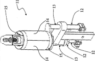
In the embodiment of describing herein and illustrate, in the lower area 26a of spacer assembly 6, seal 10 is sliding-contact, and in the upper area 26b of spacer assembly 6 (approaching outlet 17), seal 10 is dry labyrinth seal.Equipment 1 is provided with the mould 11 that is fixed on moulding press 4.Especially, each mould 11 is comprised of two half-unit 14, and described two half-unit 14 can be relative to each other at least moves between the closing position of mould 11 and open position.When mould 11 (Fig. 5) in the close position, thereby two half-unit 14 butts are formed for holding at least one chamber of parison or molded container 2.When mould 11 (Fig. 4) in an open position, two half-unit 14 changes into be arranged to separately, thereby allows molded container 2 to throw off (or introducing new parison).Each mould 11 is provided with the base member 25 that jointly limits the bottom shape of container with half portion 14 in addition.Each mould 11 is provided with locking device 15, and in described closing position, locking device 15 operatively acts on mould 11.Especially, when mould 11 is in the close position, locking device 15 can and discharge between structure in locked configuration and move.
Therefore, the open and close of mould 11 for example, is determined by being contained in opened/closed member 12 in corresponding tubular body 13 (comprise,, bar associated with it).Moving up or down of base member 25 for example, determined by being contained in rising/reduction member in corresponding tubular body 13 (comprise,, bar associated with it).
Preferably, spacer assembly 6 comprises the part 18 of collecting the liquid for pollution controlled environment 7 being cleaned or sterilize.Especially, described collection unit 18 is formed in the lower area 26a of spacer assembly 6.Can also expect having air exhauster, the steam producing for the chemical agent that environment 7 is carried out to cleaning and disinfection is discharged, or in the situation that using gaseous state or steam-like disinfectant, directly discharge the material for sterilizing.
In the lateral region 26c of spacer assembly 6, have at least one maintenance department 19, maintenance department 19 is provided with one or more accessing points 19a with tight seal protection, to allow, is polluting the interior execution adjusting of controlled environment 7, maintenance or size change operation.Preferably, described shielded accessing points 19a has the tight seal sleeve with work gloves operation.In the embodiment of describing herein and illustrate, (for example see Fig. 2), can expect having multiple adjacent maintenance departments 19, each maintenance department has two shielded accessing points 19a.
In addition, in the interior existence of spacer assembly 6, at least one changes the part of the necessary instrument of operation for depositing adjusting, maintenance and size.In spacer assembly 6, be also formed with at least one for depositing the part that is suitable for environment 7 to monitor the equipment sampling with microorganism.
From Fig. 6, can see, equipment 1 comprises parison loading part 23, and parison loading part 23 can be connected with parison treating stations 21 (thereby guaranteeing the tight seal barrier to external environment condition), so that the parison that reception & disposal is crossed.Preferably, parison treating stations 21 is equipped with baking box, for heating the parison of sending into before bottle blowing.Equipment 1 comprises the unloading part 24 for molded container 2, and unloading part 24 can be connected with the work station 22 for filling containers 2 (thereby guaranteeing the tight seal barrier to external environment condition).
To describe according to the function of the equipment for the molded container being obtained by parison of the present invention below.
In treating stations 21, after heating, parison is delivered to molded station 3 by loading part 23.The pollution controlled environment 7 at molded station 3 has carried out in advance C.I.P. and S.I.P. processes, thereby has reduced the existence of bacterium, mould or other pollutants.Waste liquid is gathered in collection unit 18 and subsequently and removes from spacer assembly 6, and the steam producing is discharged from.
In molded station 3, there is the first carousel (not shown) and the second carousel 28.The first carousel is for being transported to rotating circular disk conveyer belt 20, the second carousels 28 for molded container 2 is transported to filling station 22 from described rotating circular disk conveyer belt 20 by parison.Each parison is inserted between the two half-unit 14 of the mould 11 of opening accordingly.In this stage, half portion 14 is not attached to parison, and therefore parison supports and remain in half portion 14 by personal module (not shown).Thereby two half-unit 14 is gradually near making mould 11 closures, and locking device 15 (for example consist of ring, described ring moves by corresponding bar) starts effect subsequently.Especially, between 20 moving periods of rotating circular disk conveyer belt, the opened/closed member 12 of each mould 11, in the corresponding interior rotation of tubular body 13, is close together half portion 14 more.In mutual close final stage, the base member 25 of mould 11 engages with half portion 14 by raising/reduce the longitudinal sliding motion of member in corresponding tubular body 13.Once mould 11 is completely closed, the bar of locking device 15 is just in the corresponding interior longitudinal sliding motion of tubular body 13, thereby mould 11 can be locked in and close closing position.Finally, mould 11 closures, and parison is contained in the chamber that mould 11 limits.
In order to obtain container 2, parison is processed subsequently, for example, stretch and bottle blowing.
In bottle blowing ending phase, when rotating circular disk conveyer belt 20 rotates, the bar of locking device 15 is in their the interior longitudinal sliding motion of tubular body 13, thereby makes ring separately separately.The opened/closed member 12 of mould 11, in the interior rotation of tubular body 13, makes half portion 14 separately, at rising/reduction member of tubular body 13 interior longitudinal sliding motions separately, base member 25 and half portion 14 is departed from.Finally, mould 11 is opened, and molded container 2 is caught and takes out from mould 11 by specific member, and is transported to the second carousel 28.
Thus obtained container 2 is transported to filling station 22 by unloading part 24.
Because the pollution of environment 7 keeps being controlled, so the molded of container 2 occurs under aseptic condition.If need to pollute in controlled environment 7 keep in repair, adjusting or size change operation; operating personnel are placed on its arm in the sleeve of shielded accessing points 19a so, utilize the work gloves taking providing to be placed on the instrument in the storage part in spacer assembly 6.Operating personnel also can carry out microorganism sampling operation to environment 7 by the suitable monitoring of taking and sampling equipment.
According to the feature of the equipment for the molded container being obtained by parison of the present invention, from provided description, become apparent, its advantage is like this equally.
Especially, because spacer assembly is only applied to moulding press (being rotating circular disk conveyer belt in this article), therefore equipment is compact.
In addition, because being positioned at, pollutes outside controlled environment driven unit, so any dirt on driven unit (dust, lubricating oil) gather the environment that all can't affect rotating circular disk conveyer belt place, thereby can easily pollution be maintained and pollute in the level of expecting.Further, this set of driven unit makes operating personnel in the situation that not entering pollution controlled environment, to these assemblies, to carry out maintenance and adjustment operation.As a result, compared with existing scheme, reduce and even eliminated the risk of polluting, operation also can more easily be carried out sooner.
In addition; owing to carrying out (utilizing sleeve and work gloves) in maintenance, adjusting and the size change operation of polluting in controlled environment by shielded accessing points, so operating personnel can manual operation in environment in the situation that directly not contacting with environment.And, operate necessary instrument and be positioned at environment, therefore never have in personnel or instrument entered environment itself.As a result, compared with existing scheme, reduce and eliminated the risk of polluting even completely.The existence of the seal between movable part and the fixed part of spacer assembly and correctly maintain the pressure rating in environment, has guaranteed that the pollution of environment maintains in aspiration level.
The minimizing of pollution risk with for the system that drives mould motion, be closely related.Due to tubular body portion be positioned at and pollute controlled environment and be positioned partially at the layout of polluting outside controlled environment, mould opened/closed member can rotate and free from environmental pollution in described tubular body.In addition, mold bottom element raise/reduce member can be in tubular body separately longitudinal sliding motion and free from environmental pollution.The bar of locking device (that is, ring) slides and free from environmental pollution equally in tubular body separately.Obviously, by the specific configuration of mould self, make just the possibility that is configured as of driven unit.
In addition, because operating personnel directly do not enter pollution controlled environment, therefore do not need to open spacer assembly and enter to allow; Operating personnel extend into its arm in the sleeve of accessing points just enough, and this can at any time carry out.As a result, compared with prior art, carry out the required time of various operations to greatly reduce.
Finally, because the tight seal between molded station and parison treating stations and between molded station and filling station is connected, can create aseptic, pollute controlled bottling line.Because moulding press (as bottle blowing machine) is subject to the protection of spacer assembly, spacer assembly makes environmental pollution can keep controlled, thus preferably before bottle blowing to parison disinfection.Compared with carrying out disinfection with to bottle, due to parison be rule cylindrical, compactness, easily handle and easily heating and indeformable, therefore parison is carried out disinfection more convenient.
Claims (11)
1. one kind for using the bottle blowing die control equipment (1) of bottling line of asptic technique, comprising:
Molded station (3), described molded station (3) is equipped with bottle blowing moulding press (4), described bottle blowing moulding press (4) is for having the type of rotating circular disk conveyer belt (20), for the molded container being obtained by plastic parison of bottle blowing;
Be fixed on the mould (11) of described bottle blowing moulding press (4), each mould (11) comprises two half-unit (14), base member (25) and for the clamping device (15) of described mould (11), described two half-unit (14) can be relative to each other moves between the closing position of described mould (11) and open position, described base member (25) and described half portion (14) limit the bottom shape of described container (2) jointly, described clamping device (15) can described mould (11) during in described closing position in locked configuration with discharge between structure and move, described clamping device (15) consists of the ring moving by bar,
The driven unit (5) of described bottle blowing moulding press (4), described driven unit (5) comprises for the opened/closed drive member (12) of mould described in open and close (11) with for raising and reducing rising/reduction drive member of described base member (25);
For the spacer assembly (6) of described moulding press (4), described spacer assembly (6) plays the effect that limits the pollution controlled environment for holding described bottle blowing moulding press (4) (7), described driven unit (5) is positioned at outside described environment (7)
It is characterized in that, described bottle blowing die control equipment (1) comprises and is partly arranged in described environment (7) and is partly arranged in the outer tubular body (13) of described environment (7), described tubular body (13) is limited with tubular cavity, described tubular cavity is suitable for for the described opened/closed drive member (12) that can rotate in corresponding tubular body (13), described rising/reduction drive member that can longitudinal sliding motion in corresponding tubular body (13) and can passing through at the bar of the described clamping device (15) of longitudinal sliding motion in tubular body (13) accordingly.
2. equipment according to claim 1 (1), wherein, described spacer assembly (6) comprise fixed part (6b) and with described moulding press (4) all-in-one-piece movable part (6a), between the described movable part (6a) of described spacer assembly (6) and fixed part (6b), be provided with at least one seal (10).
3. equipment according to claim 2 (1), wherein, multiple seals (10) are arranged between the described movable part (6a) and fixed part (6b) of described spacer assembly (6).
4. equipment according to claim 1 (1), wherein, the gaseous fluid of introducing by least one entrance (16) of described spacer assembly (6) flows through described pollution controlled environment, and at least one outlet (17) by described spacer assembly (6) is discharged, described at least one entrance (16) of described spacer assembly (6) and described at least one outlet (17) are determined size according to predetermined mutual ratio, thereby maintain described fluid under predetermined pressure.
5. equipment according to claim 4 (1), wherein, described spacer assembly (6) is provided with filter, and described filter is assemblied in described at least one entrance (16), to described gaseous fluid is filtered.
6. equipment according to claim 2 (1), wherein, described at least one seal (10) is sliding-contact type or mechanical labyrinth type.
7. according to the equipment (1) described in any one in aforementioned claim 1 to 6, wherein, described spacer assembly (6) is provided with and collects for described pollution controlled environment (7) being carried out to the part (18) of the liquid of cleaning and disinfection.
8. according to the equipment (1) described in any one in aforementioned claim 1 to 6; wherein; described spacer assembly (6) is provided with at least one maintenance department (19); described at least one maintenance department (19) has one or more accessing points (19a) with tight seal protection, thereby can in described pollution controlled environment (7), regulate, maintenance or size change operation.
9. according to the equipment (1) described in any one in aforementioned claim 1 to 6, wherein, described spacer assembly (6) is provided with at least one for holding the storage part of carrying out adjusting, maintenance or the necessary instrument of size change operation.
10. according to the equipment (1) described in any one in aforementioned claim 1 to 6, wherein, described spacer assembly (6) is provided with at least one for holding the storage part that is suitable for described environment (7) to monitor the equipment sampling with microorganism.
11. according to the equipment (1) described in any one in aforementioned claim 1 to 6, further comprise parison loading part (23) and the unloading part (24) for molded container (2), described loading part (23) can be connected with the work station (21) for the treatment of described parison, the parison of crossing with reception & disposal, described unloading part (24) can be connected with the work station (22) for filling described container (2), so that molded container (2) is transported to this work station (22).
Applications Claiming Priority (2)
| Application Number | Priority Date | Filing Date | Title |
|---|---|---|---|
| EP09425161.8 | 2009-04-28 | ||
| EP09425161.8A EP2246176B2 (en) | 2009-04-28 | 2009-04-28 | Apparatus for molding containers obtained from parisons |
Publications (2)
| Publication Number | Publication Date |
|---|---|
| CN101875237A CN101875237A (en) | 2010-11-03 |
| CN101875237B true CN101875237B (en) | 2014-05-07 |
Family
ID=41077697
Family Applications (1)
| Application Number | Title | Priority Date | Filing Date |
|---|---|---|---|
| CN201010169107.0A Active CN101875237B (en) | 2009-04-28 | 2010-04-28 | Apparatus for molding containers obtained from parisons |
Country Status (6)
| Country | Link |
|---|---|
| US (1) | US8197245B2 (en) |
| EP (1) | EP2246176B2 (en) |
| JP (1) | JP5495318B2 (en) |
| CN (1) | CN101875237B (en) |
| AT (1) | ATE539871T1 (en) |
| RU (1) | RU2445205C2 (en) |
Families Citing this family (33)
| Publication number | Priority date | Publication date | Assignee | Title |
|---|---|---|---|---|
| DE102009040978A1 (en) * | 2009-09-11 | 2011-03-17 | Krones Ag | Magazine device for blow molding with cleaning device |
| DE102010022128B4 (en) * | 2010-05-20 | 2012-03-15 | Krones Aktiengesellschaft | Device for forming plastic preforms with sterile space |
| DE102010045832B4 (en) * | 2010-09-20 | 2023-10-19 | Krones Aktiengesellschaft | Aseptic sterilization unit for clean rooms on a blowing wheel |
| IT1403369B1 (en) | 2010-12-23 | 2013-10-17 | Gea Procomac Spa | PROCEDURE FOR STERILIZING AND INTRODUCING FORMING MOLDS IN AN ASEPTIC BOTTLING LINE |
| DE102011008132A1 (en) | 2011-01-04 | 2012-07-05 | Khs Corpoplast Gmbh | Method and device for blow-molding sterile containers |
| DE102011013118A1 (en) * | 2011-03-04 | 2012-09-06 | Krones Aktiengesellschaft | Blowing machine with sterile room and media supply in the sterile room |
| DE102011013126A1 (en) * | 2011-03-04 | 2012-09-06 | Krones Aktiengesellschaft | Blowing machine with blow mold locking in the clean room |
| DE102011016854A1 (en) * | 2011-04-13 | 2012-10-18 | Krones Aktiengesellschaft | Apparatus and method for forming plastic preforms into plastic containers with coupled pivoting and locking movements |
| DE102011101256A1 (en) * | 2011-05-11 | 2012-11-15 | Krones Aktiengesellschaft | Aseptic blow molding machine with sterile air discharge |
| DE102011102090B4 (en) | 2011-05-19 | 2018-02-08 | Khs Corpoplast Gmbh | Method for cleaning and / or disinfecting a device for producing containers filled with a liquid product and apparatus |
| DE102011104316A1 (en) * | 2011-06-03 | 2012-12-06 | Krones Aktiengesellschaft | Device and system for insert blowing plastic preforms and use of a ceramic component |
| DE102011122853B4 (en) * | 2011-08-11 | 2015-01-22 | Krones Aktiengesellschaft | Blow molding machine, method for exchanging blowing station components and beverage bottling plant and / or beverage container manufacturing plant |
| DE102011052574A1 (en) * | 2011-08-11 | 2013-02-14 | Krones Aktiengesellschaft | Blow molding machine, method for exchanging blowing station components and beverage bottling plant and / or beverage container manufacturing plant |
| ITPR20130017A1 (en) | 2013-03-11 | 2014-09-12 | Gea Procomac Spa | CLOSING TREATMENT SYSTEM FOR CONTAINERS USING A STERILIZING SUBSTANCE |
| ITPR20130016A1 (en) | 2013-03-11 | 2014-09-12 | Gea Procomac Spa | CLOSING TREATMENT SYSTEM FOR CONTAINERS USING A STERILIZING SUBSTANCE |
| DE202013103477U1 (en) * | 2013-08-02 | 2014-11-04 | Krones Ag | Container treatment machine with a gutter |
| US9050749B1 (en) * | 2014-01-10 | 2015-06-09 | Chumpower Machinery Corp. | Blow molding device for a rotary bottle blowing machine |
| JP6585702B2 (en) | 2014-07-21 | 2019-10-02 | ゲア プロコマック エセ.ピ.ア.Gea Procomac S.P.A. | Molding device for molding a container starting with a parison of plastic material and a molding mechanism comprising this device |
| EP3172028B1 (en) | 2014-07-21 | 2018-05-02 | Gea Procomac S.p.A. | Method for moulding and sterilizing a container made of plastic material, device for moulding and sterilizing a container made of plastic material and moulding and sterilizing machine |
| WO2016012884A1 (en) | 2014-07-21 | 2016-01-28 | Gea Procomac S.P.A. | Moulding device for moulding a container starting with a parison in plastic material, moulding method and moulding machine |
| WO2016088003A1 (en) | 2014-12-01 | 2016-06-09 | Gea Procomac S.P.A. | A production apparatus of sterile receptacles, a bottling plant comprising the apparatus and a production method of a sterile receptacle |
| WO2016088004A1 (en) | 2014-12-01 | 2016-06-09 | Gea Procomac S.P.A. | A production apparatus of sterile receptacles and a bottling plant comprising the apparatus |
| CN107001020B (en) | 2014-12-30 | 2019-03-01 | Gea普洛克玛柯股份公司 | Device and method for container filling |
| US10800088B2 (en) | 2014-12-30 | 2020-10-13 | Gea Procomac S.P.A. | Process station for a parison or a container made of thermoplastic material, apparatus for processing parisons or containers, production and packaging line for producing and packaging the containers and method for producing and packaging containers |
| WO2018061946A1 (en) | 2016-09-28 | 2018-04-05 | 大日本印刷株式会社 | Device and method for heating preforms, aseptic blow moulding machine, and aseptic blow moulding method |
| IT201800001700A1 (en) | 2018-01-23 | 2019-07-23 | Gea Procomac Spa | APPARATUS AND PROCESS FOR ASEPTIC FORMING OF CONTAINERS STARTING FROM PREFORMS IN THERMOPLASTIC MATERIAL |
| IT201800002781A1 (en) | 2018-02-16 | 2019-08-16 | Gea Procomac Spa | ASEPTIC IRON-BLOWER DEVICE FOR A PREFORM IN THERMOPLASTIC MATERIAL |
| IT201800007667A1 (en) | 2018-07-31 | 2020-01-31 | Gea Procomac Spa | APPARATUS AND PROCEDURE FOR DECONTAMINATION OF THE INLET OF A PREFORM OR A CONTAINER IN THERMOPLASTIC MATERIAL |
| IT201900007220A1 (en) | 2019-05-24 | 2020-11-24 | Gea Procomac Spa | MOLD FOR FORMING A CONTAINER STARTING FROM A PREFORM IN THERMOPLASTIC MATERIAL AND RELATED FORMING PROCESS |
| IT201900010134A1 (en) * | 2019-06-26 | 2020-12-26 | Sidel Participations Sas | RECIPIENT TREATMENT PLANT SUITABLE TO CONTAIN A VERSABLE PRODUCT |
| EP3888884B1 (en) | 2020-03-30 | 2022-05-04 | Gea Procomac S.p.A. | Apparatus and process for aseptically forming containers starting from parisons made of a thermoplastic material |
| IT202000009112A1 (en) | 2020-04-27 | 2021-10-27 | Gea Procomac Spa | ASEPTIC FORMING STATION OF A CONTAINER STARTING FROM A PREFORM MADE OF THERMOPLASTIC MATERIAL, ASEPTIC FORMING APPARATUS AND PROCESS |
| IT202000009685A1 (en) * | 2020-05-04 | 2021-11-04 | Smi Spa | MACHINE FOR PACKAGING LIQUIDS OR SEMI-SOLID PRODUCTS IN CONTAINERS |
Citations (5)
| Publication number | Priority date | Publication date | Assignee | Title |
|---|---|---|---|---|
| EP0741080A1 (en) * | 1995-05-01 | 1996-11-06 | Ashland Inc. | Integrated container molding and filling facility |
| US5759218A (en) * | 1996-10-24 | 1998-06-02 | Allergan | Point of fill air system |
| EP1445011A1 (en) * | 2003-02-10 | 2004-08-11 | Staubfresser GmbH | Air purification fan |
| CN101124117A (en) * | 2005-02-23 | 2008-02-13 | 西拉克集团公司 | Aseptic packaging installation comprising aseptic buffer zones |
| US7393373B1 (en) * | 2004-06-14 | 2008-07-01 | H.K. Plastics Engineering, Inc. | Portable clean molding apparatus and method of use |
Family Cites Families (18)
| Publication number | Priority date | Publication date | Assignee | Title |
|---|---|---|---|---|
| US4208852A (en) * | 1974-11-08 | 1980-06-24 | Pont-A-Mousson S.A. | Process for the aseptic packing of products and machine employing said process |
| DE3729451C1 (en) * | 1987-09-03 | 1988-06-16 | Berstorff Gmbh Masch Hermann | Device for exact and quick opening and closing of the two mold halves of a blow mold |
| NL9001504A (en) * | 1990-07-02 | 1992-02-03 | Stork Amsterdam | METHOD AND APPARATUS FOR MANUFACTURING PLASTIC CONTAINERS, SUCH AS BOTTLES, WITH A MULTILAYER WALL. |
| IT1279846B1 (en) † | 1995-08-11 | 1997-12-18 | Rossi & Catelli Spa | CONTINUOUS ASEPTIC BOTTLING SYSTEM |
| DE29713155U1 (en) † | 1997-07-24 | 1998-09-10 | Krones Ag Hermann Kronseder Maschinenfabrik, 93073 Neutraubling | Rotary filler |
| DE19821280A1 (en) † | 1998-05-13 | 1999-11-18 | Groninger & Co Gmbh | Locking device between a non-sterile area and a sterile area |
| US6447281B1 (en) † | 1998-09-11 | 2002-09-10 | Sidel, Inc. | Blow mold shell and shell holder assembly for blow-molding machine |
| JP4074400B2 (en) * | 1999-01-13 | 2008-04-09 | 日精エー・エス・ビー機械株式会社 | Air conditioner for injection stretch blow molding machine |
| DE10140906B4 (en) * | 2001-08-21 | 2004-02-12 | Krones Ag | Method and device for blowing out plastic preforms |
| DE10323335A1 (en) * | 2003-05-23 | 2004-12-16 | Hansen, Bernd, Dipl.-Ing. | Fabrication |
| DE102004045405A1 (en) † | 2004-09-18 | 2006-04-13 | Sig Technology Ltd. | Device for blow molding containers |
| DE102006053193A1 (en) * | 2006-11-09 | 2008-05-15 | Krones Ag | Apparatus and method for producing plastic containers |
| KR101350703B1 (en) * | 2007-02-26 | 2014-01-10 | 도요세이칸 그룹 홀딩스 가부시키가이샤 | Blow molding machine with air conditioning |
| DE102007017938C5 (en) * | 2007-04-13 | 2017-09-21 | Khs Gmbh | Container manufacturing apparatus and mold production method |
| FR2914875B1 (en) † | 2007-04-13 | 2009-07-10 | Sidel Participations | MOLDING DEVICE FOR THE MANUFACTURE OF THERMOPLASTIC CONTAINERS BY BLOWING OR STRETCH BLOWING. |
| FR2915127B1 (en) † | 2007-04-20 | 2012-10-12 | Sidel Participations | INSTALLATION FOR THE MANUFACTURE OF CONTAINERS COMPRISING A PROTECTION ENCLOSURE EQUIPPED WITH A SYSTEM OF AIR FILTER INSUFFLATION |
| DE102008017768A1 (en) † | 2008-04-08 | 2009-10-15 | Groninger & Co. Gmbh | Locking device, particularly for use in pharmaceutical industry, has boundary, which is provided between unsterile area and sterile area, through which movable driving element extends into sterile area |
| DE102008038141A1 (en) * | 2008-08-18 | 2010-02-25 | Krones Ag | Device for forming plastic preforms with sterile space |
-
2009
- 2009-04-28 AT AT09425161T patent/ATE539871T1/en active
- 2009-04-28 EP EP09425161.8A patent/EP2246176B2/en active Active
-
2010
- 2010-04-27 RU RU2010116715/05A patent/RU2445205C2/en not_active IP Right Cessation
- 2010-04-27 US US12/768,410 patent/US8197245B2/en active Active
- 2010-04-28 CN CN201010169107.0A patent/CN101875237B/en active Active
- 2010-04-28 JP JP2010103764A patent/JP5495318B2/en active Active
Patent Citations (5)
| Publication number | Priority date | Publication date | Assignee | Title |
|---|---|---|---|---|
| EP0741080A1 (en) * | 1995-05-01 | 1996-11-06 | Ashland Inc. | Integrated container molding and filling facility |
| US5759218A (en) * | 1996-10-24 | 1998-06-02 | Allergan | Point of fill air system |
| EP1445011A1 (en) * | 2003-02-10 | 2004-08-11 | Staubfresser GmbH | Air purification fan |
| US7393373B1 (en) * | 2004-06-14 | 2008-07-01 | H.K. Plastics Engineering, Inc. | Portable clean molding apparatus and method of use |
| CN101124117A (en) * | 2005-02-23 | 2008-02-13 | 西拉克集团公司 | Aseptic packaging installation comprising aseptic buffer zones |
Also Published As
| Publication number | Publication date |
|---|---|
| JP5495318B2 (en) | 2014-05-21 |
| RU2010116715A (en) | 2011-11-27 |
| ATE539871T1 (en) | 2012-01-15 |
| US8197245B2 (en) | 2012-06-12 |
| EP2246176A1 (en) | 2010-11-03 |
| US20100272844A1 (en) | 2010-10-28 |
| EP2246176B2 (en) | 2019-12-04 |
| EP2246176B1 (en) | 2012-01-04 |
| JP2010264753A (en) | 2010-11-25 |
| RU2445205C2 (en) | 2012-03-20 |
| CN101875237A (en) | 2010-11-03 |
Similar Documents
| Publication | Publication Date | Title |
|---|---|---|
| CN101875237B (en) | Apparatus for molding containers obtained from parisons | |
| CN102310547B (en) | Device for reforming plastic pre-forms with a sterile area | |
| CN101992541B (en) | Blow-moulding machine with cleaning system | |
| US20140196415A1 (en) | Method and device for cleaning and/or disinfecting a device for producing containers filled with a liquid filling material | |
| EP2340157B1 (en) | Device for blowing and stretching a plastic parison for obtaining a container | |
| US8708681B2 (en) | Blow-moulding machine with blow mould locking in the clean room | |
| CN102825775B (en) | Blow moulding machine with pivot shafts guided on slide bearings | |
| ITPR20090061A1 (en) | METHOD AND PLANT TO PRODUCE, FILL AND CLOSE CONTAINERS | |
| US20140174034A1 (en) | Method and device for producing filled containers made from preforms | |
| CN104441579A (en) | Apparatus for the shaping of plastics material pre-forms with a clean room | |
| JP6026183B2 (en) | Blow molding apparatus having a detachable blow molding station | |
| CN104441586A (en) | Blow moulding machine with a pneumatically operated blow air valve and a method for operating such a blow moulding machine | |
| CN102837418A (en) | Device and method for reforming plastic pre-form into plastic container with air extraction guided through surge tank | |
| EP2495088B1 (en) | Sterile blow moulding device and method with non-sterile media supply | |
| EP2495090B1 (en) | Blow moulding machine with sterile area and media supply in the sterile area | |
| CN104339627A (en) | Sterilization blowing machine | |
| CN106273363A (en) | There is sterilizing room and liquid is discharged the container processing systems of sterilizing room | |
| CN103538167B (en) | For the aseptic firing equipment of plastic preform | |
| CA2143575C (en) | Device for sterile filling of containers | |
| CN220883364U (en) | System for manufacturing filled plastic containers made from sterilized plastic preforms | |
| DE102011013120A1 (en) | Blow molding machine with sterile room and sterile blast air supply | |
| CN103429090A (en) | Mould drum and cleaning apparatus for mould drum |
Legal Events
| Date | Code | Title | Description |
|---|---|---|---|
| C06 | Publication | ||
| PB01 | Publication | ||
| C10 | Entry into substantive examination | ||
| SE01 | Entry into force of request for substantive examination | ||
| C14 | Grant of patent or utility model | ||
| GR01 | Patent grant |