EP2468478A1 - Process for sterilising and introducing forming moulds into an aseptic bottling line - Google Patents
Process for sterilising and introducing forming moulds into an aseptic bottling line Download PDFInfo
- Publication number
- EP2468478A1 EP2468478A1 EP11191024A EP11191024A EP2468478A1 EP 2468478 A1 EP2468478 A1 EP 2468478A1 EP 11191024 A EP11191024 A EP 11191024A EP 11191024 A EP11191024 A EP 11191024A EP 2468478 A1 EP2468478 A1 EP 2468478A1
- Authority
- EP
- European Patent Office
- Prior art keywords
- depositing chamber
- sterilising
- moulds
- bottling line
- forming
- Prior art date
- Legal status (The legal status is an assumption and is not a legal conclusion. Google has not performed a legal analysis and makes no representation as to the accuracy of the status listed.)
- Granted
Links
- 230000001954 sterilising effect Effects 0.000 title claims abstract description 44
- 238000000034 method Methods 0.000 title claims abstract description 19
- 230000008569 process Effects 0.000 title claims abstract description 19
- 238000000151 deposition Methods 0.000 claims abstract description 46
- 238000004891 communication Methods 0.000 claims abstract description 5
- 239000012530 fluid Substances 0.000 claims abstract description 5
- 239000003795 chemical substances by application Substances 0.000 claims description 23
- 238000004659 sterilization and disinfection Methods 0.000 claims description 9
- 238000010438 heat treatment Methods 0.000 claims description 4
- 230000001105 regulatory effect Effects 0.000 claims description 3
- 239000003518 caustics Substances 0.000 claims description 2
- 239000003599 detergent Substances 0.000 claims description 2
- 238000001035 drying Methods 0.000 claims 1
- 238000001914 filtration Methods 0.000 description 5
- 238000004519 manufacturing process Methods 0.000 description 5
- MHAJPDPJQMAIIY-UHFFFAOYSA-N Hydrogen peroxide Chemical compound OO MHAJPDPJQMAIIY-UHFFFAOYSA-N 0.000 description 2
- 230000009471 action Effects 0.000 description 2
- 238000011109 contamination Methods 0.000 description 2
- 230000036512 infertility Effects 0.000 description 2
- 239000000126 substance Substances 0.000 description 2
- 238000011144 upstream manufacturing Methods 0.000 description 2
- 238000007664 blowing Methods 0.000 description 1
- 230000008859 change Effects 0.000 description 1
- 238000009833 condensation Methods 0.000 description 1
- 230000005494 condensation Effects 0.000 description 1
- 230000008878 coupling Effects 0.000 description 1
- 238000010168 coupling process Methods 0.000 description 1
- 238000005859 coupling reaction Methods 0.000 description 1
- 238000007599 discharging Methods 0.000 description 1
- 239000000428 dust Substances 0.000 description 1
- 238000005516 engineering process Methods 0.000 description 1
- 238000009434 installation Methods 0.000 description 1
- 239000012212 insulator Substances 0.000 description 1
- 239000010687 lubricating oil Substances 0.000 description 1
- 239000000463 material Substances 0.000 description 1
- 210000000056 organ Anatomy 0.000 description 1
Images

Classifications
-
- B—PERFORMING OPERATIONS; TRANSPORTING
- B29—WORKING OF PLASTICS; WORKING OF SUBSTANCES IN A PLASTIC STATE IN GENERAL
- B29C—SHAPING OR JOINING OF PLASTICS; SHAPING OF MATERIAL IN A PLASTIC STATE, NOT OTHERWISE PROVIDED FOR; AFTER-TREATMENT OF THE SHAPED PRODUCTS, e.g. REPAIRING
- B29C49/00—Blow-moulding, i.e. blowing a preform or parison to a desired shape within a mould; Apparatus therefor
- B29C49/42—Component parts, details or accessories; Auxiliary operations
- B29C49/46—Component parts, details or accessories; Auxiliary operations characterised by using particular environment or blow fluids other than air
-
- B—PERFORMING OPERATIONS; TRANSPORTING
- B29—WORKING OF PLASTICS; WORKING OF SUBSTANCES IN A PLASTIC STATE IN GENERAL
- B29C—SHAPING OR JOINING OF PLASTICS; SHAPING OF MATERIAL IN A PLASTIC STATE, NOT OTHERWISE PROVIDED FOR; AFTER-TREATMENT OF THE SHAPED PRODUCTS, e.g. REPAIRING
- B29C31/00—Handling, e.g. feeding of the material to be shaped, storage of plastics material before moulding; Automation, i.e. automated handling lines in plastics processing plants, e.g. using manipulators or robots
- B29C31/006—Handling moulds, e.g. between a mould store and a moulding machine
-
- B—PERFORMING OPERATIONS; TRANSPORTING
- B29—WORKING OF PLASTICS; WORKING OF SUBSTANCES IN A PLASTIC STATE IN GENERAL
- B29C—SHAPING OR JOINING OF PLASTICS; SHAPING OF MATERIAL IN A PLASTIC STATE, NOT OTHERWISE PROVIDED FOR; AFTER-TREATMENT OF THE SHAPED PRODUCTS, e.g. REPAIRING
- B29C49/00—Blow-moulding, i.e. blowing a preform or parison to a desired shape within a mould; Apparatus therefor
- B29C49/42—Component parts, details or accessories; Auxiliary operations
- B29C49/46—Component parts, details or accessories; Auxiliary operations characterised by using particular environment or blow fluids other than air
- B29C2049/4673—Environments
- B29C2049/4679—Sterile gas to surround or flush parts of the blow-moulding apparatus, e.g. blowing means, preforms or parisons
-
- B—PERFORMING OPERATIONS; TRANSPORTING
- B29—WORKING OF PLASTICS; WORKING OF SUBSTANCES IN A PLASTIC STATE IN GENERAL
- B29C—SHAPING OR JOINING OF PLASTICS; SHAPING OF MATERIAL IN A PLASTIC STATE, NOT OTHERWISE PROVIDED FOR; AFTER-TREATMENT OF THE SHAPED PRODUCTS, e.g. REPAIRING
- B29C49/00—Blow-moulding, i.e. blowing a preform or parison to a desired shape within a mould; Apparatus therefor
- B29C49/42—Component parts, details or accessories; Auxiliary operations
- B29C49/46—Component parts, details or accessories; Auxiliary operations characterised by using particular environment or blow fluids other than air
- B29C2049/4673—Environments
- B29C2049/4697—Clean room
Definitions
- the present invention relates to a process for sterilising and introducing forming moulds into an aseptic bottling line.
- European patent application EP2246176 filed by the present Applicant, described the use of an isolating device suitable for defining a controlled-contamination environment housing at least the forming machine (blower) and, preferably, also the kiln and other work stations of a bottling line.
- the movement organs of the moulds of the blower, at which dirt tends to collect are located outside the insulator such as to reduce the risks of contamination in the line.
- each mould is constituted by two half-portions or half-moulds, and by a profiling element of the bottom of the recipient, commonly known in the sector by the term "bottom".
- a first idea was to subject the forming moulds to a preliminary cycle of chemical or heat sterilisation out of the bottling line and, successively, to a further chemical sterilisation in-line, i.e. after the installation of the moulds on the blower and together with the sterilisation of the forming machine (blower).
- the technical aim at the basis of the present invention is to provide a process for sterilising and introducing forming moulds into an aseptic bottling line, which obviates the drawbacks in the prior art cited herein above.
- an aim of the present invention is to provide a process for sterilising and introducing forming moulds into an aseptic bottling line, which enables management of the change-format rapidly, limiting the halts in the production cycles.
- a further aim of the present invention is to make available a process for sterilising and introducing forming moulds into an aseptic bottling line, which enables maintaining the consumption of sterilising agents and energy at low levels.
- a further aim of the present invention is to provide a process for sterilising and introducing forming moulds into an aseptic bottling line, which also enables uniform sterilisation of the mould holders.
- the set technical objective and the specified aims are substantially attained by a process for sterilising and introducing forming moulds into an aseptic bottling line, comprising the technical characteristics set out in one or more of the accompanying claims.
- number 1 denotes an aseptic bottling line comprising a heating station 2 of preforms made of a plastic material, a sterilising station 3 of the preforms and a forming station 4 of the recipients starting from the heated preforms.
- a rotating carousel blower is installed, bearing a plurality of forming moulds of recipients by stretch-blowing.
- the bottling line 1 comprises a filling and capping station of the formed recipients.
- a depositing chamber 5 of forming moulds is arranged by a flank of the forming station 4.
- the depositing chamber 5 is separated from the forming station 4 by a hermetically-closed door 6.
- the depositing chamber 5, which is part of a sterilising system 10 of the forming moulds, is configurable in at least two states. In a first state, the depositing chamber 5 is insulated from the outside so that the moulds are subjected to the action of a sterilising agent (for example, hydrogen peroxide). In a second state, the depositing chamber 5 is connectable in fluid communication with the forming station 4 such that the moulds can be transferred thereto.
- a sterilising agent for example, hydrogen peroxide
- the passage of the depositing chamber 5 from the first state to the second state is obtained with the opening of the hermetically-sealed door 6.
- the sterilising system 10 of the moulds comprises a pressurising plant 7 operatively active on the depositing chamber 5 in such a way as to impose pressure values that are different in the two above-indicated states.
- a first predefined pressure P1 is imposed therein.
- a second predefined pressure P2 is set in it, higher than the first predefined pressure P1.
- the first pressure P1 is preferably lower than or equal to 20 Pa, while the second predefined pressure P2 is comprised between 20 Pa and 30 Pa.
- the pressurising plant 7 is preferably connected to the sterilising station 3 of the preforms such as to receive the residual sterilising agent present therein.
- the supply of the sterilising agent to the pressurising plant 7 is done by a dedicated unit 8.
- a heating element 9 is preferably interposed between the pressurising plant 7 and the depositing chamber 5, with the aim of preventing condensation of the sterilising agent.
- An element (not illustrated) is preferably located upstream of the depositing chamber 5, for regulating the concentration of the sterilising agent in such a way that it stays below a maximum predetermined level L.
- the predetermined maximum level L is 2000 ppm.
- At least a filtering element 11 is preferably present for filtering the pressurising air.
- the moulds are arranged internally of the depositing chamber 5. They are preferably subjected to a preliminary sanitisation with a caustic detergent internally of the depositing chamber 5 such as to eliminate any residual organic residues.
- the hermetically-sealed door 6 is closed in such a way that the depositing chamber 5 is insulated from the forming station 4.
- the sterilising agent coming from the sterilising station 3 of the preforms or from the dedicated supply unit 8 is in the steam phase, it is heated by the heating element 9 and filtered by the filtering element 11.
- the filtering element 11 is therefore sterilised by the passage of the sterilising agent. In this way, the walls of the depositing chamber 5 and the moulds are also dried.
- the sterilising agent is preferably subjected to the action of the regulating element of the concentration, which mixes the agent with external air, and is then filtered by the filtering element 11.
- the pressurising plant 7 imposes the first pressure P1 predefined internally of the depositing chamber 5.
- the exhausted sterilising agent is evacuated from the depositing chamber 5 via an air intake 12 or a discharging channel 13.
- no evacuation of the sterilising agent is included from the depositing chamber 5.
- the pressurising plant 7 brings the depositing chamber 5 to the second predefined pressure P2.
- the depositing chamber 5 is then set in fluid communication with the forming station 4 such that the depositing chamber 5 and the forming station 4 define a single environment, microbiologically insulated from the outside atmosphere.
- the depositing chamber 5 is set in fluid communication with the forming station 4 by means of opening the hermetically-sealed door 6.
- the bottling line 1 temporarily halts the production cycle such as to make transfer of the moulds possible from the depositing chamber 5 to the forming station 4. Once the moulds have been installed, the bottling line 1 starts or restarts its production cycle.
- the format change is achieved very rapidly, thus limiting halts in the production cycle.
- the sterility of the forming station is guaranteed by the pressurisation plant, which increases the pressure in the depositing chamber during the step of transferring the moulds.
Abstract
introducing a sterilising agent into a depositing chamber (5) housing the moulds, the depositing chamber (5) being separated from the bottling line (1) and being at a first predefined pressure (P1);
establishing a second predefined pressure (P2) internally of the depositing chamber (5), which second pressure (P2) is higher than the first predefined pressure (P1);
placing the depositing chamber (5) in fluid communication with a forming station (4) of recipients of the bottling line (1);
transferring the moulds from the depositing chamber (5) to the forming station (4).
Description
- The present invention relates to a process for sterilising and introducing forming moulds into an aseptic bottling line.
- The need to sterilise forming moulds developed only recently, together with the evolution of aseptic technology. European patent application
EP2246176 , filed by the present Applicant, described the use of an isolating device suitable for defining a controlled-contamination environment housing at least the forming machine (blower) and, preferably, also the kiln and other work stations of a bottling line. The movement organs of the moulds of the blower, at which dirt tends to collect (dust, lubricating oils) are located outside the insulator such as to reduce the risks of contamination in the line. - With this structure of the bottling line, the problem of sterilisation of the forming moulds arises. As is known, each mould is constituted by two half-portions or half-moulds, and by a profiling element of the bottom of the recipient, commonly known in the sector by the term "bottom".
- A first idea was to subject the forming moulds to a preliminary cycle of chemical or heat sterilisation out of the bottling line and, successively, to a further chemical sterilisation in-line, i.e. after the installation of the moulds on the blower and together with the sterilisation of the forming machine (blower).
- However, the above-illustrated solution would lead to various drawbacks.
- Firstly, in case of format changing, the production process would have to be stopped so that the moulds could be changed. Further, there would be a high consumption of sterilising agent, as well as use of energy for the functioning of the plant. Finally, the interface zone between the moulds and the relative mould holders is not easily accessible by the sterilising agents. In this context, the technical aim at the basis of the present invention is to provide a process for sterilising and introducing forming moulds into an aseptic bottling line, which obviates the drawbacks in the prior art cited herein above.
- In particular, an aim of the present invention is to provide a process for sterilising and introducing forming moulds into an aseptic bottling line, which enables management of the change-format rapidly, limiting the halts in the production cycles.
- A further aim of the present invention is to make available a process for sterilising and introducing forming moulds into an aseptic bottling line, which enables maintaining the consumption of sterilising agents and energy at low levels.
- A further aim of the present invention is to provide a process for sterilising and introducing forming moulds into an aseptic bottling line, which also enables uniform sterilisation of the mould holders.
- The set technical objective and the specified aims are substantially attained by a process for sterilising and introducing forming moulds into an aseptic bottling line, comprising the technical characteristics set out in one or more of the accompanying claims.
- Further characteristics and advantages of the present invention will more fully emerge from the description, provided by way of non-limiting example, of a preferred but not exclusive embodiment of a process for sterilising and introducing forming moulds into an aseptic bottling line, as illustrated in the appended drawings, in which:
-
figure 1 is a sterilising system for forming moulds, employing the process according to the present invention, in a schematic view; -
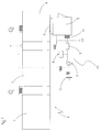
figure 2 is an aseptic bottling line in which the depositing chamber of the sterilisation system offigure 1 is visible, from above and in a simplified view. - With reference to the figures,
number 1 denotes an aseptic bottling line comprising aheating station 2 of preforms made of a plastic material, asterilising station 3 of the preforms and a formingstation 4 of the recipients starting from the heated preforms. In particular, in the forming station 4 a rotating carousel blower is installed, bearing a plurality of forming moulds of recipients by stretch-blowing. In a further embodiment (not illustrated), thebottling line 1 comprises a filling and capping station of the formed recipients. - A depositing
chamber 5 of forming moulds is arranged by a flank of the formingstation 4. In the embodiment described and illustrated herein, the depositingchamber 5 is separated from the formingstation 4 by a hermetically-closed door 6. Thedepositing chamber 5, which is part of asterilising system 10 of the forming moulds, is configurable in at least two states. In a first state, the depositingchamber 5 is insulated from the outside so that the moulds are subjected to the action of a sterilising agent (for example, hydrogen peroxide). In a second state, thedepositing chamber 5 is connectable in fluid communication with the formingstation 4 such that the moulds can be transferred thereto. - In the embodiment described and illustrated herein, the passage of the
depositing chamber 5 from the first state to the second state is obtained with the opening of the hermetically-sealed door 6. - The
sterilising system 10 of the moulds comprises apressurising plant 7 operatively active on the depositingchamber 5 in such a way as to impose pressure values that are different in the two above-indicated states. In particular, when thedepositing chamber 5 is in the first state, a first predefined pressure P1 is imposed therein. When thedepositing chamber 5 is in the second state, a second predefined pressure P2 is set in it, higher than the first predefined pressure P1. The first pressure P1 is preferably lower than or equal to 20 Pa, while the second predefined pressure P2 is comprised between 20 Pa and 30 Pa. - The pressurising
plant 7 is preferably connected to thesterilising station 3 of the preforms such as to receive the residual sterilising agent present therein. - Alternatively, the supply of the sterilising agent to the pressurising
plant 7 is done by adedicated unit 8. - A
heating element 9 is preferably interposed between thepressurising plant 7 and thedepositing chamber 5, with the aim of preventing condensation of the sterilising agent. - An element (not illustrated) is preferably located upstream of the
depositing chamber 5, for regulating the concentration of the sterilising agent in such a way that it stays below a maximum predetermined level L. - For example, the predetermined maximum level L is 2000 ppm.
- Upstream of the
depositing chamber 5 at least a filteringelement 11 is preferably present for filtering the pressurising air. - The process for sterilising and introducing forming moulds in an aseptic bottling line, according to the present invention, is described in the following.
- The moulds are arranged internally of the
depositing chamber 5. They are preferably subjected to a preliminary sanitisation with a caustic detergent internally of thedepositing chamber 5 such as to eliminate any residual organic residues. - Initially the hermetically-sealed door 6 is closed in such a way that the depositing
chamber 5 is insulated from the formingstation 4. In a case in which the sterilising agent coming from thesterilising station 3 of the preforms or from thededicated supply unit 8 is in the steam phase, it is heated by theheating element 9 and filtered by thefiltering element 11. The filteringelement 11 is therefore sterilised by the passage of the sterilising agent. In this way, the walls of thedepositing chamber 5 and the moulds are also dried. The sterilising agent is preferably subjected to the action of the regulating element of the concentration, which mixes the agent with external air, and is then filtered by thefiltering element 11. The pressurisingplant 7 imposes the first pressure P1 predefined internally of thedepositing chamber 5. - On completion of the sterilisation of the moulds, the exhausted sterilising agent is evacuated from the
depositing chamber 5 via anair intake 12 or adischarging channel 13. - In a further embodiment, no evacuation of the sterilising agent is included from the depositing
chamber 5. - At this point, the
pressurising plant 7 brings the depositingchamber 5 to the second predefined pressure P2. - The depositing
chamber 5 is then set in fluid communication with the formingstation 4 such that the depositingchamber 5 and the formingstation 4 define a single environment, microbiologically insulated from the outside atmosphere. In the embodiment described and illustrated herein, the depositingchamber 5 is set in fluid communication with the formingstation 4 by means of opening the hermetically-sealed door 6. Thebottling line 1 temporarily halts the production cycle such as to make transfer of the moulds possible from the depositingchamber 5 to the formingstation 4. Once the moulds have been installed, thebottling line 1 starts or restarts its production cycle. - From the above description, the characteristics of the process for sterilising and introducing forming moulds into an aseptic bottling line according to the present invention emerge clearly, as do the advantages thereof.
- In particular, thanks to the arranging of the depositing chamber adjacent to the forming station, and thanks to the fact that the transfer of the moulds is done by opening the door between the depositing chamber and the forming station without compromising the sterility of the line, the format change is achieved very rapidly, thus limiting halts in the production cycle.
- The sterility of the forming station is guaranteed by the pressurisation plant, which increases the pressure in the depositing chamber during the step of transferring the moulds.
- Further, where there is a recuperation of the sterilising agent from the sterilising station of the preforms, consumption of sterilising agent is significantly reduced.
- Further, thanks to the fact that the sterilisation of the moulds is done laterally to the blower (for which reason the moulds and the mould-holders are separatedly sterilised) but in an environment which possibly communicates therewith, it is possible to uniformly sterilise all the coupling surfaces, comprising the backs of the moulds, before installing the moulds themselves.
Claims (7)
- Process for sterilising and introducing forming moulds in an aseptic bottling line (1), characterised in that it comprises the steps of:introducing a sterilising agent into a depositing chamber (5) housing the moulds, said depositing chamber (5) being separated from the bottling line (1) and being at a first predefined pressure (P1);establishing a second predefined pressure (P2) internally of the depositing chamber (5), which second pressure is higher than the first predefined pressure (P1);placing the depositing chamber (5) in fluid communication with a forming station (4) of recipients of the bottling line (1) in such a way that said depositing chamber (5) and said forming station (4) define a single environment which is microbiologically isolated from the outside;transferring the moulds from the depositing chamber (5) to the forming station (4).
- Process according to claim 1, wherein the sterilising agent to be introduced into the depositing chamber (5) is recuperated by a sterilising station (3) of the bottling line (1).
- Process according to claim 1 or 2, further comprising the step of heating the sterilising agent before introducing the sterilising agent into the depositing chamber (5).
- Process according to any one of the preceding claims, further comprising the step of regulating the concentration of the sterilising agent introduced into the depositing chamber (5) such that said concentration is maintained below a maximum predetermined level (L).
- Process according to any one of the preceding claims, further comprising the step of evacuating the exhausted sterilising agent from said depositing chamber (5) after having completed its sterilization.
- Process according to any one of the preceding claims, further comprising the step of sanitising the forming moulds with a caustic detergent internally of the depositing chamber (5) in such a way as to eliminate any organic residues, said step of sanitising occurring before the step of introducing the sterilising agent into the depositing chamber (5).
- Process according to any one of the preceding claims, further comprising the step of drying the forming moulds and the walls defining the depositing chamber (5) by means of the heated pressurized air.
Applications Claiming Priority (1)
| Application Number | Priority Date | Filing Date | Title |
|---|---|---|---|
| ITPR2010A000095A IT1403369B1 (en) | 2010-12-23 | 2010-12-23 | PROCEDURE FOR STERILIZING AND INTRODUCING FORMING MOLDS IN AN ASEPTIC BOTTLING LINE |
Publications (2)
| Publication Number | Publication Date |
|---|---|
| EP2468478A1 true EP2468478A1 (en) | 2012-06-27 |
| EP2468478B1 EP2468478B1 (en) | 2013-02-20 |
Family
ID=43737231
Family Applications (1)
| Application Number | Title | Priority Date | Filing Date |
|---|---|---|---|
| EP11191024A Active EP2468478B1 (en) | 2010-12-23 | 2011-11-28 | Process for sterilising and introducing forming moulds into an aseptic bottling line |
Country Status (2)
| Country | Link |
|---|---|
| EP (1) | EP2468478B1 (en) |
| IT (1) | IT1403369B1 (en) |
Cited By (2)
| Publication number | Priority date | Publication date | Assignee | Title |
|---|---|---|---|---|
| US20180281265A1 (en) * | 2015-12-18 | 2018-10-04 | Krones Ag | Changing blow moulds in blow-moulding machines |
| WO2019007704A1 (en) * | 2017-07-03 | 2019-01-10 | Krones Ag | Installation for producing beverage containers, with sterilization of the blow-moulding machine |
Families Citing this family (1)
| Publication number | Priority date | Publication date | Assignee | Title |
|---|---|---|---|---|
| DE102017110272A1 (en) * | 2017-05-11 | 2018-11-15 | Krones Ag | Method for sterilizing a blow molding machine and blow molding machine |
Citations (2)
| Publication number | Priority date | Publication date | Assignee | Title |
|---|---|---|---|---|
| WO2008055685A1 (en) * | 2006-11-09 | 2008-05-15 | Krones Ag | Device and method for the production of plastic containers |
| EP2246176A1 (en) | 2009-04-28 | 2010-11-03 | Gea Procomac S.p.A. | Apparatus for molding containers obtained from parisons |
Family Cites Families (1)
| Publication number | Priority date | Publication date | Assignee | Title |
|---|---|---|---|---|
| US7569180B2 (en) * | 2004-10-12 | 2009-08-04 | Ethicon, Inc. | Sterilization system and method and orifice inlet control apparatus therefor |
-
2010
- 2010-12-23 IT ITPR2010A000095A patent/IT1403369B1/en active
-
2011
- 2011-11-28 EP EP11191024A patent/EP2468478B1/en active Active
Patent Citations (2)
| Publication number | Priority date | Publication date | Assignee | Title |
|---|---|---|---|---|
| WO2008055685A1 (en) * | 2006-11-09 | 2008-05-15 | Krones Ag | Device and method for the production of plastic containers |
| EP2246176A1 (en) | 2009-04-28 | 2010-11-03 | Gea Procomac S.p.A. | Apparatus for molding containers obtained from parisons |
Cited By (4)
| Publication number | Priority date | Publication date | Assignee | Title |
|---|---|---|---|---|
| US20180281265A1 (en) * | 2015-12-18 | 2018-10-04 | Krones Ag | Changing blow moulds in blow-moulding machines |
| US10953589B2 (en) * | 2015-12-18 | 2021-03-23 | Krones Ag | Changing blow moulds in blow-moulding machines |
| WO2019007704A1 (en) * | 2017-07-03 | 2019-01-10 | Krones Ag | Installation for producing beverage containers, with sterilization of the blow-moulding machine |
| US11351713B2 (en) | 2017-07-03 | 2022-06-07 | Krones Ag | Plant for producing beverage containers with sterilisation of the blow moulding machine |
Also Published As
| Publication number | Publication date |
|---|---|
| ITPR20100095A1 (en) | 2012-06-24 |
| IT1403369B1 (en) | 2013-10-17 |
| EP2468478B1 (en) | 2013-02-20 |
Similar Documents
| Publication | Publication Date | Title |
|---|---|---|
| JP5504269B2 (en) | Apparatus for molding plastic material container and method for molding plastic material container | |
| CN101618596B (en) | Apparatus and method for manufacturing plastic containers | |
| JP5969849B2 (en) | Blow molding apparatus, method for replacing components of a blow molding station, and beverage filling plant and / or beverage container manufacturing plant | |
| CN102028292B (en) | Food sterilization method and food sterilization apparatus | |
| JP2014065301A (en) | Method for producing beverage containers and replacement of blow-moulded articles | |
| US8632325B2 (en) | Apparatus for shaping plastics material pre-forms with a sterile room | |
| CN103702688B (en) | For the production of the method and apparatus of the container for drink of filling liquid | |
| EP2468478B1 (en) | Process for sterilising and introducing forming moulds into an aseptic bottling line | |
| EP3351503B1 (en) | Method of decontaminating an aseptic filling apparatus | |
| CN102700112B (en) | Blow moulding machine with a sterile chamber and heating | |
| CN103566387B (en) | It is used for processing the apparatus and method of container lid | |
| US20130154164A1 (en) | Apparatus for the processing of plastics material containers, beverage filling plant and/or beverage container production plant and method of shaping plastics material pre-forms as well as use of heating path conveying means | |
| CN105682887A (en) | Bottle sterilization method and device | |
| CN105636868A (en) | Preform sterilization method and device | |
| US20110309557A1 (en) | Blow moulding machine with feed line sterilization | |
| CN102247610A (en) | Blow mould capable of being sterilized | |
| JP2016514071A (en) | Method and apparatus for manufacturing and filling containers | |
| CN103025505A (en) | Container manufacturing plant comprising an air recycling circuit and recycling method | |
| CN103687712A (en) | Method and device for producing filled containers made from preforms | |
| US10456954B2 (en) | Method and apparatus for shaping plastics material pre-forms into plastics material containers | |
| CN104415383A (en) | System for sterilizing plastic parisons with simultaneous internal and external sterilization | |
| CN102672941B (en) | Sterile blow moulding device with non sterilization medium supplying | |
| CN109676902B (en) | Blow molding machine with clean room and container removal device | |
| US20220324154A1 (en) | Means of sterilizing the stretching means of a container molding device, and container manufacturing installation | |
| CN105396162A (en) | Method For Interim Sterilization Of At Least One Surface In An Insulator Of A System For Treating Containers |
Legal Events
| Date | Code | Title | Description |
|---|---|---|---|
| 17P | Request for examination filed |
Effective date: 20120326 |
|
| AK | Designated contracting states |
Kind code of ref document: A1 Designated state(s): AL AT BE BG CH CY CZ DE DK EE ES FI FR GB GR HR HU IE IS IT LI LT LU LV MC MK MT NL NO PL PT RO RS SE SI SK SM TR |
|
| AX | Request for extension of the european patent |
Extension state: BA ME |
|
| PUAI | Public reference made under article 153(3) epc to a published international application that has entered the european phase |
Free format text: ORIGINAL CODE: 0009012 |
|
| GRAP | Despatch of communication of intention to grant a patent |
Free format text: ORIGINAL CODE: EPIDOSNIGR1 |
|
| GRAS | Grant fee paid |
Free format text: ORIGINAL CODE: EPIDOSNIGR3 |
|
| GRAA | (expected) grant |
Free format text: ORIGINAL CODE: 0009210 |
|
| AK | Designated contracting states |
Kind code of ref document: B1 Designated state(s): AL AT BE BG CH CY CZ DE DK EE ES FI FR GB GR HR HU IE IS IT LI LT LU LV MC MK MT NL NO PL PT RO RS SE SI SK SM TR |
|
| REG | Reference to a national code |
Ref country code: GB Ref legal event code: FG4D |
|
| REG | Reference to a national code |
Ref country code: CH Ref legal event code: EP |
|
| REG | Reference to a national code |
Ref country code: AT Ref legal event code: REF Ref document number: 597340 Country of ref document: AT Kind code of ref document: T Effective date: 20130315 |
|
| REG | Reference to a national code |
Ref country code: IE Ref legal event code: FG4D |
|
| REG | Reference to a national code |
Ref country code: DE Ref legal event code: R096 Ref document number: 602011000933 Country of ref document: DE Effective date: 20130425 |
|
| REG | Reference to a national code |
Ref country code: NL Ref legal event code: VDEP Effective date: 20130220 |
|
| REG | Reference to a national code |
Ref country code: LT Ref legal event code: MG4D |
|
| PG25 | Lapsed in a contracting state [announced via postgrant information from national office to epo] |
Ref country code: NO Free format text: LAPSE BECAUSE OF FAILURE TO SUBMIT A TRANSLATION OF THE DESCRIPTION OR TO PAY THE FEE WITHIN THE PRESCRIBED TIME-LIMIT Effective date: 20130520 Ref country code: ES Free format text: LAPSE BECAUSE OF FAILURE TO SUBMIT A TRANSLATION OF THE DESCRIPTION OR TO PAY THE FEE WITHIN THE PRESCRIBED TIME-LIMIT Effective date: 20130531 Ref country code: SE Free format text: LAPSE BECAUSE OF FAILURE TO SUBMIT A TRANSLATION OF THE DESCRIPTION OR TO PAY THE FEE WITHIN THE PRESCRIBED TIME-LIMIT Effective date: 20130220 Ref country code: BG Free format text: LAPSE BECAUSE OF FAILURE TO SUBMIT A TRANSLATION OF THE DESCRIPTION OR TO PAY THE FEE WITHIN THE PRESCRIBED TIME-LIMIT Effective date: 20130520 Ref country code: LT Free format text: LAPSE BECAUSE OF FAILURE TO SUBMIT A TRANSLATION OF THE DESCRIPTION OR TO PAY THE FEE WITHIN THE PRESCRIBED TIME-LIMIT Effective date: 20130220 Ref country code: IS Free format text: LAPSE BECAUSE OF FAILURE TO SUBMIT A TRANSLATION OF THE DESCRIPTION OR TO PAY THE FEE WITHIN THE PRESCRIBED TIME-LIMIT Effective date: 20130620 |
|
| PG25 | Lapsed in a contracting state [announced via postgrant information from national office to epo] |
Ref country code: FI Free format text: LAPSE BECAUSE OF FAILURE TO SUBMIT A TRANSLATION OF THE DESCRIPTION OR TO PAY THE FEE WITHIN THE PRESCRIBED TIME-LIMIT Effective date: 20130220 Ref country code: GR Free format text: LAPSE BECAUSE OF FAILURE TO SUBMIT A TRANSLATION OF THE DESCRIPTION OR TO PAY THE FEE WITHIN THE PRESCRIBED TIME-LIMIT Effective date: 20130521 Ref country code: PL Free format text: LAPSE BECAUSE OF FAILURE TO SUBMIT A TRANSLATION OF THE DESCRIPTION OR TO PAY THE FEE WITHIN THE PRESCRIBED TIME-LIMIT Effective date: 20130220 Ref country code: PT Free format text: LAPSE BECAUSE OF FAILURE TO SUBMIT A TRANSLATION OF THE DESCRIPTION OR TO PAY THE FEE WITHIN THE PRESCRIBED TIME-LIMIT Effective date: 20130620 Ref country code: BE Free format text: LAPSE BECAUSE OF FAILURE TO SUBMIT A TRANSLATION OF THE DESCRIPTION OR TO PAY THE FEE WITHIN THE PRESCRIBED TIME-LIMIT Effective date: 20130220 Ref country code: LV Free format text: LAPSE BECAUSE OF FAILURE TO SUBMIT A TRANSLATION OF THE DESCRIPTION OR TO PAY THE FEE WITHIN THE PRESCRIBED TIME-LIMIT Effective date: 20130220 Ref country code: SI Free format text: LAPSE BECAUSE OF FAILURE TO SUBMIT A TRANSLATION OF THE DESCRIPTION OR TO PAY THE FEE WITHIN THE PRESCRIBED TIME-LIMIT Effective date: 20130220 |
|
| PG25 | Lapsed in a contracting state [announced via postgrant information from national office to epo] |
Ref country code: HR Free format text: LAPSE BECAUSE OF FAILURE TO SUBMIT A TRANSLATION OF THE DESCRIPTION OR TO PAY THE FEE WITHIN THE PRESCRIBED TIME-LIMIT Effective date: 20130220 Ref country code: RS Free format text: LAPSE BECAUSE OF FAILURE TO SUBMIT A TRANSLATION OF THE DESCRIPTION OR TO PAY THE FEE WITHIN THE PRESCRIBED TIME-LIMIT Effective date: 20130220 |
|
| PG25 | Lapsed in a contracting state [announced via postgrant information from national office to epo] |
Ref country code: NL Free format text: LAPSE BECAUSE OF FAILURE TO SUBMIT A TRANSLATION OF THE DESCRIPTION OR TO PAY THE FEE WITHIN THE PRESCRIBED TIME-LIMIT Effective date: 20130220 Ref country code: CZ Free format text: LAPSE BECAUSE OF FAILURE TO SUBMIT A TRANSLATION OF THE DESCRIPTION OR TO PAY THE FEE WITHIN THE PRESCRIBED TIME-LIMIT Effective date: 20130220 Ref country code: EE Free format text: LAPSE BECAUSE OF FAILURE TO SUBMIT A TRANSLATION OF THE DESCRIPTION OR TO PAY THE FEE WITHIN THE PRESCRIBED TIME-LIMIT Effective date: 20130220 Ref country code: SK Free format text: LAPSE BECAUSE OF FAILURE TO SUBMIT A TRANSLATION OF THE DESCRIPTION OR TO PAY THE FEE WITHIN THE PRESCRIBED TIME-LIMIT Effective date: 20130220 Ref country code: RO Free format text: LAPSE BECAUSE OF FAILURE TO SUBMIT A TRANSLATION OF THE DESCRIPTION OR TO PAY THE FEE WITHIN THE PRESCRIBED TIME-LIMIT Effective date: 20130220 Ref country code: DK Free format text: LAPSE BECAUSE OF FAILURE TO SUBMIT A TRANSLATION OF THE DESCRIPTION OR TO PAY THE FEE WITHIN THE PRESCRIBED TIME-LIMIT Effective date: 20130220 |
|
| PLBE | No opposition filed within time limit |
Free format text: ORIGINAL CODE: 0009261 |
|
| STAA | Information on the status of an ep patent application or granted ep patent |
Free format text: STATUS: NO OPPOSITION FILED WITHIN TIME LIMIT |
|
| 26N | No opposition filed |
Effective date: 20131121 |
|
| REG | Reference to a national code |
Ref country code: DE Ref legal event code: R097 Ref document number: 602011000933 Country of ref document: DE Effective date: 20131121 |
|
| PG25 | Lapsed in a contracting state [announced via postgrant information from national office to epo] |
Ref country code: MC Free format text: LAPSE BECAUSE OF FAILURE TO SUBMIT A TRANSLATION OF THE DESCRIPTION OR TO PAY THE FEE WITHIN THE PRESCRIBED TIME-LIMIT Effective date: 20130220 |
|
| REG | Reference to a national code |
Ref country code: IE Ref legal event code: MM4A |
|
| PG25 | Lapsed in a contracting state [announced via postgrant information from national office to epo] |
Ref country code: IE Free format text: LAPSE BECAUSE OF NON-PAYMENT OF DUE FEES Effective date: 20131128 |
|
| PG25 | Lapsed in a contracting state [announced via postgrant information from national office to epo] |
Ref country code: SM Free format text: LAPSE BECAUSE OF FAILURE TO SUBMIT A TRANSLATION OF THE DESCRIPTION OR TO PAY THE FEE WITHIN THE PRESCRIBED TIME-LIMIT Effective date: 20130220 |
|
| PG25 | Lapsed in a contracting state [announced via postgrant information from national office to epo] |
Ref country code: CY Free format text: LAPSE BECAUSE OF FAILURE TO SUBMIT A TRANSLATION OF THE DESCRIPTION OR TO PAY THE FEE WITHIN THE PRESCRIBED TIME-LIMIT Effective date: 20130220 Ref country code: TR Free format text: LAPSE BECAUSE OF FAILURE TO SUBMIT A TRANSLATION OF THE DESCRIPTION OR TO PAY THE FEE WITHIN THE PRESCRIBED TIME-LIMIT Effective date: 20130220 |
|
| REG | Reference to a national code |
Ref country code: CH Ref legal event code: PL |
|
| PG25 | Lapsed in a contracting state [announced via postgrant information from national office to epo] |
Ref country code: LI Free format text: LAPSE BECAUSE OF NON-PAYMENT OF DUE FEES Effective date: 20141130 Ref country code: LU Free format text: LAPSE BECAUSE OF NON-PAYMENT OF DUE FEES Effective date: 20131128 Ref country code: CH Free format text: LAPSE BECAUSE OF NON-PAYMENT OF DUE FEES Effective date: 20141130 Ref country code: HU Free format text: LAPSE BECAUSE OF FAILURE TO SUBMIT A TRANSLATION OF THE DESCRIPTION OR TO PAY THE FEE WITHIN THE PRESCRIBED TIME-LIMIT; INVALID AB INITIO Effective date: 20111128 Ref country code: MK Free format text: LAPSE BECAUSE OF FAILURE TO SUBMIT A TRANSLATION OF THE DESCRIPTION OR TO PAY THE FEE WITHIN THE PRESCRIBED TIME-LIMIT Effective date: 20130220 |
|
| PG25 | Lapsed in a contracting state [announced via postgrant information from national office to epo] |
Ref country code: MT Free format text: LAPSE BECAUSE OF FAILURE TO SUBMIT A TRANSLATION OF THE DESCRIPTION OR TO PAY THE FEE WITHIN THE PRESCRIBED TIME-LIMIT Effective date: 20130220 |
|
| REG | Reference to a national code |
Ref country code: FR Ref legal event code: PLFP Year of fee payment: 5 |
|
| GBPC | Gb: european patent ceased through non-payment of renewal fee |
Effective date: 20151128 |
|
| PG25 | Lapsed in a contracting state [announced via postgrant information from national office to epo] |
Ref country code: GB Free format text: LAPSE BECAUSE OF NON-PAYMENT OF DUE FEES Effective date: 20151128 |
|
| REG | Reference to a national code |
Ref country code: FR Ref legal event code: PLFP Year of fee payment: 6 |
|
| REG | Reference to a national code |
Ref country code: FR Ref legal event code: PLFP Year of fee payment: 7 |
|
| PG25 | Lapsed in a contracting state [announced via postgrant information from national office to epo] |
Ref country code: AL Free format text: LAPSE BECAUSE OF FAILURE TO SUBMIT A TRANSLATION OF THE DESCRIPTION OR TO PAY THE FEE WITHIN THE PRESCRIBED TIME-LIMIT Effective date: 20130220 |
|
| P01 | Opt-out of the competence of the unified patent court (upc) registered |
Effective date: 20230526 |
|
| PGFP | Annual fee paid to national office [announced via postgrant information from national office to epo] |
Ref country code: IT Payment date: 20231129 Year of fee payment: 13 Ref country code: FR Payment date: 20231123 Year of fee payment: 13 Ref country code: DE Payment date: 20231127 Year of fee payment: 13 Ref country code: AT Payment date: 20231117 Year of fee payment: 13 |