EP3520992B1 - Device and method for heating preforms, aseptic blow moulding machine, and aseptic blow moulding method - Google Patents
Device and method for heating preforms, aseptic blow moulding machine, and aseptic blow moulding method Download PDFInfo
- Publication number
- EP3520992B1 EP3520992B1 EP17855901.9A EP17855901A EP3520992B1 EP 3520992 B1 EP3520992 B1 EP 3520992B1 EP 17855901 A EP17855901 A EP 17855901A EP 3520992 B1 EP3520992 B1 EP 3520992B1
- Authority
- EP
- European Patent Office
- Prior art keywords
- preform
- aseptic
- disinfectant
- heating
- heating unit
- Prior art date
- Legal status (The legal status is an assumption and is not a legal conclusion. Google has not performed a legal analysis and makes no representation as to the accuracy of the status listed.)
- Active
Links
- 238000010438 heat treatment Methods 0.000 title claims description 239
- 238000000071 blow moulding Methods 0.000 title claims description 68
- 238000000034 method Methods 0.000 title claims description 24
- 239000000645 desinfectant Substances 0.000 claims description 172
- 230000001954 sterilising effect Effects 0.000 claims description 77
- 239000003595 mist Substances 0.000 claims description 40
- 239000000203 mixture Substances 0.000 claims description 36
- 238000005507 spraying Methods 0.000 claims description 25
- 238000000465 moulding Methods 0.000 description 132
- 239000007789 gas Substances 0.000 description 67
- 230000036512 infertility Effects 0.000 description 46
- MHAJPDPJQMAIIY-UHFFFAOYSA-N Hydrogen peroxide Chemical compound OO MHAJPDPJQMAIIY-UHFFFAOYSA-N 0.000 description 32
- 239000007788 liquid Substances 0.000 description 30
- 238000007689 inspection Methods 0.000 description 27
- 238000011049 filling Methods 0.000 description 22
- 238000004659 sterilization and disinfection Methods 0.000 description 16
- 241000894006 Bacteria Species 0.000 description 14
- 238000007664 blowing Methods 0.000 description 13
- 230000008016 vaporization Effects 0.000 description 9
- 238000007789 sealing Methods 0.000 description 8
- -1 polyethylene terephthalate Polymers 0.000 description 7
- 239000007921 spray Substances 0.000 description 7
- 238000012371 Aseptic Filling Methods 0.000 description 6
- KFSLWBXXFJQRDL-UHFFFAOYSA-N Peracetic acid Chemical compound CC(=O)OO KFSLWBXXFJQRDL-UHFFFAOYSA-N 0.000 description 6
- 229910052736 halogen Inorganic materials 0.000 description 6
- 238000002955 isolation Methods 0.000 description 6
- 150000002367 halogens Chemical class 0.000 description 5
- 238000011109 contamination Methods 0.000 description 4
- 238000010586 diagram Methods 0.000 description 4
- 230000008569 process Effects 0.000 description 4
- 229920005992 thermoplastic resin Polymers 0.000 description 4
- ZWEHNKRNPOVVGH-UHFFFAOYSA-N 2-Butanone Chemical compound CCC(C)=O ZWEHNKRNPOVVGH-UHFFFAOYSA-N 0.000 description 3
- QTBSBXVTEAMEQO-UHFFFAOYSA-N Acetic acid Chemical compound CC(O)=O QTBSBXVTEAMEQO-UHFFFAOYSA-N 0.000 description 3
- CSCPPACGZOOCGX-UHFFFAOYSA-N Acetone Chemical compound CC(C)=O CSCPPACGZOOCGX-UHFFFAOYSA-N 0.000 description 3
- KFZMGEQAYNKOFK-UHFFFAOYSA-N Isopropanol Chemical compound CC(C)O KFZMGEQAYNKOFK-UHFFFAOYSA-N 0.000 description 3
- OKKJLVBELUTLKV-UHFFFAOYSA-N Methanol Chemical compound OC OKKJLVBELUTLKV-UHFFFAOYSA-N 0.000 description 3
- KWYUFKZDYYNOTN-UHFFFAOYSA-M Potassium hydroxide Chemical compound [OH-].[K+] KWYUFKZDYYNOTN-UHFFFAOYSA-M 0.000 description 3
- HEMHJVSKTPXQMS-UHFFFAOYSA-M Sodium hydroxide Chemical compound [OH-].[Na+] HEMHJVSKTPXQMS-UHFFFAOYSA-M 0.000 description 3
- 230000007547 defect Effects 0.000 description 3
- 230000000694 effects Effects 0.000 description 3
- 238000010894 electron beam technology Methods 0.000 description 3
- XLYOFNOQVPJJNP-UHFFFAOYSA-N water Substances O XLYOFNOQVPJJNP-UHFFFAOYSA-N 0.000 description 3
- LFQSCWFLJHTTHZ-UHFFFAOYSA-N Ethanol Chemical compound CCO LFQSCWFLJHTTHZ-UHFFFAOYSA-N 0.000 description 2
- LRHPLDYGYMQRHN-UHFFFAOYSA-N N-Butanol Chemical compound CCCCO LRHPLDYGYMQRHN-UHFFFAOYSA-N 0.000 description 2
- YRKCREAYFQTBPV-UHFFFAOYSA-N acetylacetone Chemical compound CC(=O)CC(C)=O YRKCREAYFQTBPV-UHFFFAOYSA-N 0.000 description 2
- 230000004913 activation Effects 0.000 description 2
- 238000004061 bleaching Methods 0.000 description 2
- 150000001875 compounds Chemical class 0.000 description 2
- 230000008878 coupling Effects 0.000 description 2
- 238000010168 coupling process Methods 0.000 description 2
- 238000005859 coupling reaction Methods 0.000 description 2
- 230000002950 deficient Effects 0.000 description 2
- 238000002845 discoloration Methods 0.000 description 2
- 238000004090 dissolution Methods 0.000 description 2
- 235000019441 ethanol Nutrition 0.000 description 2
- 239000012530 fluid Substances 0.000 description 2
- 239000000314 lubricant Substances 0.000 description 2
- IVSZLXZYQVIEFR-UHFFFAOYSA-N m-xylene Chemical group CC1=CC=CC(C)=C1 IVSZLXZYQVIEFR-UHFFFAOYSA-N 0.000 description 2
- 229910052751 metal Inorganic materials 0.000 description 2
- 239000002184 metal Substances 0.000 description 2
- 238000011144 upstream manufacturing Methods 0.000 description 2
- 229920000219 Ethylene vinyl alcohol Polymers 0.000 description 1
- GRYLNZFGIOXLOG-UHFFFAOYSA-N Nitric acid Chemical compound O[N+]([O-])=O GRYLNZFGIOXLOG-UHFFFAOYSA-N 0.000 description 1
- CBENFWSGALASAD-UHFFFAOYSA-N Ozone Chemical compound [O-][O+]=O CBENFWSGALASAD-UHFFFAOYSA-N 0.000 description 1
- 239000004952 Polyamide Substances 0.000 description 1
- 239000004698 Polyethylene Substances 0.000 description 1
- 239000004743 Polypropylene Substances 0.000 description 1
- BQCADISMDOOEFD-UHFFFAOYSA-N Silver Chemical compound [Ag] BQCADISMDOOEFD-UHFFFAOYSA-N 0.000 description 1
- 239000005708 Sodium hypochlorite Substances 0.000 description 1
- 239000002253 acid Substances 0.000 description 1
- 239000000654 additive Substances 0.000 description 1
- 230000000996 additive effect Effects 0.000 description 1
- 150000001298 alcohols Chemical class 0.000 description 1
- 229910052782 aluminium Inorganic materials 0.000 description 1
- XAGFODPZIPBFFR-UHFFFAOYSA-N aluminium Chemical compound [Al] XAGFODPZIPBFFR-UHFFFAOYSA-N 0.000 description 1
- 229910000147 aluminium phosphate Inorganic materials 0.000 description 1
- 150000004982 aromatic amines Chemical class 0.000 description 1
- 230000004888 barrier function Effects 0.000 description 1
- 230000015556 catabolic process Effects 0.000 description 1
- 239000003093 cationic surfactant Substances 0.000 description 1
- 239000003795 chemical substances by application Substances 0.000 description 1
- 150000001805 chlorine compounds Chemical class 0.000 description 1
- 238000000748 compression moulding Methods 0.000 description 1
- 238000001816 cooling Methods 0.000 description 1
- 230000003247 decreasing effect Effects 0.000 description 1
- 238000006731 degradation reaction Methods 0.000 description 1
- 238000000151 deposition Methods 0.000 description 1
- MTHSVFCYNBDYFN-UHFFFAOYSA-N diethylene glycol Chemical compound OCCOCCO MTHSVFCYNBDYFN-UHFFFAOYSA-N 0.000 description 1
- 238000001035 drying Methods 0.000 description 1
- 230000005489 elastic deformation Effects 0.000 description 1
- 238000005516 engineering process Methods 0.000 description 1
- 238000001914 filtration Methods 0.000 description 1
- PCHJSUWPFVWCPO-UHFFFAOYSA-N gold Chemical compound [Au] PCHJSUWPFVWCPO-UHFFFAOYSA-N 0.000 description 1
- 229910052737 gold Inorganic materials 0.000 description 1
- 239000010931 gold Substances 0.000 description 1
- 230000005484 gravity Effects 0.000 description 1
- 125000005843 halogen group Chemical group 0.000 description 1
- 238000001746 injection moulding Methods 0.000 description 1
- 239000011810 insulating material Substances 0.000 description 1
- 230000001678 irradiating effect Effects 0.000 description 1
- 150000002576 ketones Chemical class 0.000 description 1
- 239000000463 material Substances 0.000 description 1
- 230000007246 mechanism Effects 0.000 description 1
- 239000000178 monomer Substances 0.000 description 1
- 229910017604 nitric acid Inorganic materials 0.000 description 1
- 239000002736 nonionic surfactant Substances 0.000 description 1
- 150000007524 organic acids Chemical class 0.000 description 1
- 235000005985 organic acids Nutrition 0.000 description 1
- 238000013021 overheating Methods 0.000 description 1
- NBIIXXVUZAFLBC-UHFFFAOYSA-N phosphoric acid Substances OP(O)(O)=O NBIIXXVUZAFLBC-UHFFFAOYSA-N 0.000 description 1
- 238000007747 plating Methods 0.000 description 1
- 229920003207 poly(ethylene-2,6-naphthalate) Polymers 0.000 description 1
- 229920002647 polyamide Polymers 0.000 description 1
- 229920000573 polyethylene Polymers 0.000 description 1
- 239000011112 polyethylene naphthalate Substances 0.000 description 1
- 229920000139 polyethylene terephthalate Polymers 0.000 description 1
- 239000005020 polyethylene terephthalate Substances 0.000 description 1
- 229920001155 polypropylene Polymers 0.000 description 1
- BDERNNFJNOPAEC-UHFFFAOYSA-N propan-1-ol Chemical compound CCCO BDERNNFJNOPAEC-UHFFFAOYSA-N 0.000 description 1
- 229910052709 silver Inorganic materials 0.000 description 1
- 239000004332 silver Substances 0.000 description 1
- SUKJFIGYRHOWBL-UHFFFAOYSA-N sodium hypochlorite Chemical compound [Na+].Cl[O-] SUKJFIGYRHOWBL-UHFFFAOYSA-N 0.000 description 1
- 239000000243 solution Substances 0.000 description 1
- 230000037303 wrinkles Effects 0.000 description 1
Images


Classifications
-
- B—PERFORMING OPERATIONS; TRANSPORTING
- B29—WORKING OF PLASTICS; WORKING OF SUBSTANCES IN A PLASTIC STATE IN GENERAL
- B29C—SHAPING OR JOINING OF PLASTICS; SHAPING OF MATERIAL IN A PLASTIC STATE, NOT OTHERWISE PROVIDED FOR; AFTER-TREATMENT OF THE SHAPED PRODUCTS, e.g. REPAIRING
- B29C49/00—Blow-moulding, i.e. blowing a preform or parison to a desired shape within a mould; Apparatus therefor
- B29C49/42—Component parts, details or accessories; Auxiliary operations
- B29C49/46—Component parts, details or accessories; Auxiliary operations characterised by using particular environment or blow fluids other than air
-
- B—PERFORMING OPERATIONS; TRANSPORTING
- B29—WORKING OF PLASTICS; WORKING OF SUBSTANCES IN A PLASTIC STATE IN GENERAL
- B29C—SHAPING OR JOINING OF PLASTICS; SHAPING OF MATERIAL IN A PLASTIC STATE, NOT OTHERWISE PROVIDED FOR; AFTER-TREATMENT OF THE SHAPED PRODUCTS, e.g. REPAIRING
- B29C49/00—Blow-moulding, i.e. blowing a preform or parison to a desired shape within a mould; Apparatus therefor
- B29C49/42—Component parts, details or accessories; Auxiliary operations
- B29C49/64—Heating or cooling preforms, parisons or blown articles
- B29C49/6409—Thermal conditioning of preforms
-
- B—PERFORMING OPERATIONS; TRANSPORTING
- B29—WORKING OF PLASTICS; WORKING OF SUBSTANCES IN A PLASTIC STATE IN GENERAL
- B29C—SHAPING OR JOINING OF PLASTICS; SHAPING OF MATERIAL IN A PLASTIC STATE, NOT OTHERWISE PROVIDED FOR; AFTER-TREATMENT OF THE SHAPED PRODUCTS, e.g. REPAIRING
- B29C49/00—Blow-moulding, i.e. blowing a preform or parison to a desired shape within a mould; Apparatus therefor
- B29C49/42—Component parts, details or accessories; Auxiliary operations
- B29C49/46—Component parts, details or accessories; Auxiliary operations characterised by using particular environment or blow fluids other than air
- B29C2049/4673—Environments
- B29C2049/4679—Sterile gas to surround or flush parts of the blow-moulding apparatus, e.g. blowing means, preforms or parisons
-
- B—PERFORMING OPERATIONS; TRANSPORTING
- B29—WORKING OF PLASTICS; WORKING OF SUBSTANCES IN A PLASTIC STATE IN GENERAL
- B29C—SHAPING OR JOINING OF PLASTICS; SHAPING OF MATERIAL IN A PLASTIC STATE, NOT OTHERWISE PROVIDED FOR; AFTER-TREATMENT OF THE SHAPED PRODUCTS, e.g. REPAIRING
- B29C49/00—Blow-moulding, i.e. blowing a preform or parison to a desired shape within a mould; Apparatus therefor
- B29C49/42—Component parts, details or accessories; Auxiliary operations
- B29C49/46—Component parts, details or accessories; Auxiliary operations characterised by using particular environment or blow fluids other than air
- B29C2049/4673—Environments
- B29C2049/4697—Clean room
-
- B—PERFORMING OPERATIONS; TRANSPORTING
- B29—WORKING OF PLASTICS; WORKING OF SUBSTANCES IN A PLASTIC STATE IN GENERAL
- B29C—SHAPING OR JOINING OF PLASTICS; SHAPING OF MATERIAL IN A PLASTIC STATE, NOT OTHERWISE PROVIDED FOR; AFTER-TREATMENT OF THE SHAPED PRODUCTS, e.g. REPAIRING
- B29C49/00—Blow-moulding, i.e. blowing a preform or parison to a desired shape within a mould; Apparatus therefor
- B29C49/28—Blow-moulding apparatus
- B29C49/30—Blow-moulding apparatus having movable moulds or mould parts
- B29C49/36—Blow-moulding apparatus having movable moulds or mould parts rotatable about one axis
-
- B—PERFORMING OPERATIONS; TRANSPORTING
- B29—WORKING OF PLASTICS; WORKING OF SUBSTANCES IN A PLASTIC STATE IN GENERAL
- B29C—SHAPING OR JOINING OF PLASTICS; SHAPING OF MATERIAL IN A PLASTIC STATE, NOT OTHERWISE PROVIDED FOR; AFTER-TREATMENT OF THE SHAPED PRODUCTS, e.g. REPAIRING
- B29C49/00—Blow-moulding, i.e. blowing a preform or parison to a desired shape within a mould; Apparatus therefor
- B29C49/42—Component parts, details or accessories; Auxiliary operations
- B29C49/42403—Purging or cleaning the blow-moulding apparatus
- B29C49/42405—Sterilizing
-
- B—PERFORMING OPERATIONS; TRANSPORTING
- B29—WORKING OF PLASTICS; WORKING OF SUBSTANCES IN A PLASTIC STATE IN GENERAL
- B29C—SHAPING OR JOINING OF PLASTICS; SHAPING OF MATERIAL IN A PLASTIC STATE, NOT OTHERWISE PROVIDED FOR; AFTER-TREATMENT OF THE SHAPED PRODUCTS, e.g. REPAIRING
- B29C49/00—Blow-moulding, i.e. blowing a preform or parison to a desired shape within a mould; Apparatus therefor
- B29C49/42—Component parts, details or accessories; Auxiliary operations
- B29C49/42407—Procedures for start-up or material change
-
- B—PERFORMING OPERATIONS; TRANSPORTING
- B29—WORKING OF PLASTICS; WORKING OF SUBSTANCES IN A PLASTIC STATE IN GENERAL
- B29C—SHAPING OR JOINING OF PLASTICS; SHAPING OF MATERIAL IN A PLASTIC STATE, NOT OTHERWISE PROVIDED FOR; AFTER-TREATMENT OF THE SHAPED PRODUCTS, e.g. REPAIRING
- B29C49/00—Blow-moulding, i.e. blowing a preform or parison to a desired shape within a mould; Apparatus therefor
- B29C49/42—Component parts, details or accessories; Auxiliary operations
- B29C49/42414—Treatment of preforms, e.g. cleaning or spraying water for improved heat transfer
- B29C49/42416—Purging or cleaning the preforms
- B29C49/42418—Purging or cleaning the preforms for sterilizing
-
- B—PERFORMING OPERATIONS; TRANSPORTING
- B29—WORKING OF PLASTICS; WORKING OF SUBSTANCES IN A PLASTIC STATE IN GENERAL
- B29C—SHAPING OR JOINING OF PLASTICS; SHAPING OF MATERIAL IN A PLASTIC STATE, NOT OTHERWISE PROVIDED FOR; AFTER-TREATMENT OF THE SHAPED PRODUCTS, e.g. REPAIRING
- B29C49/00—Blow-moulding, i.e. blowing a preform or parison to a desired shape within a mould; Apparatus therefor
- B29C49/42—Component parts, details or accessories; Auxiliary operations
- B29C49/4273—Auxiliary operations after the blow-moulding operation not otherwise provided for
- B29C49/4282—Purging or cleaning the article
- B29C49/42822—Sterilizing the article
Definitions
- the present invention relates to a heating apparatus and a heating method for preforms for sterilizing a preform, and heating the sterilized preform in an aseptic atmosphere.
- a sterilizing method that applies a disinfectant to a preform while continuously conveying the preform, directly introduces the preform into a heating furnace, heats the preform to a temperature for molding the preform into a container in the heating furnace, and simultaneously performs drying and activation of the disinfectant applied to the preform by this heating (Patent Literature 1).
- the preform is sterilized in the heating furnace since the disinfectant is activated in the heating furnace.
- a method or an apparatus for maintaining the sterility when molding the preform there is no description about a method or an apparatus for maintaining the sterility when molding the preform.
- a drink filling method that sprays mist or gas of a hydrogen peroxide solution on a preform, further heats the preform to a molding temperature, molds the preform that reached the molding temperature into a bottle within a blow molding die that is similarly continuously conveyed, removes the bottle from the blow molding die, and thereafter fills the bottle with a drink and seals the bottle with a lid
- Patent Literatures 2 and 3 there is a description of covering a heating unit and a molding unit, sterilizing the inside of a covered chamber before the operation of the heating unit and the molding unit, and supplying an aseptic air into the chamber at the time of the operation.
- Patent Literature 4 a method is also proposed that performs ultraviolet irradiation in the heating unit that heats the preform, so as to prevent contamination of the preform in the heating unit.
- Patent Literature 5 a method and an apparatus are proposed that sterilize the inner surface of a mold that molds a preform into a bottle. Additionally, it is also proposed to provide a mold, a blow nozzle, and an extension rod in a clean room (Patent Literature 6). However, there is a possibility that sterilization of the mold inner surface is complicated, and durability is insufficient since a bellows is used for maintaining the sterility of the extension rod.
- an apparatus and the like are proposed that set a blow nozzle and a mold of a molding machine in an aseptic atmosphere, and set the other in a non-aseptic atmosphere, sterilize a chamber in which an extension rod in the non-aseptic atmosphere is moved, so as to secure the sterility of the extension rod (Patent Literatures 7 and 8).
- a sterilization mechanism for the extension rod is complicated, and an opening of the molded bottle is directed downward, and it is difficult to direct the opening upward.
- a conveying apparatus becomes complicated, and it is necessary to provide the equipment for reversing the bottle.
- the apparatus comprises a transfer unit that transfers a preform having adsorbed a sterilizer or a bottle from a supplying stage of the preform to a molding stage of the bottle, a heating furnace that heats the preform to a temperature for a blow-molding treatment to activate the sterilizer adsorbed by the preform, thereby sterilizing the preform, and a mold that blow-molds the preform into the bottle by air.
- Document EP 3 069 847 A1 discloses a heating apparatus for preforms, the heating apparatus comprising at least a heating unit that heats a preform to a temperature for blow molding of the preform into a bottle, and a driving unit that drives the heating unit, wherein the heating unit includes at least a heater, a reflector, a spindle, an endless chain, and a pulley for rotating the endless chain, the heating unit is covered by a heating unit chamber, and a sterilizing apparatus that sterilizes an inside and an inner surface of the heating unit chamber is provided.
- an aseptic filling machine for bottles molds a preform into a bottle, and sterilizes the molded bottle.
- an aseptic filling machine that performs sterilization at the stage of a preform is becoming widely used.
- it is necessary to convey a bottle while maintaining the sterility until the molded bottle is filled with a content, after the sterilization is performed at the stage of the preform, and the preform is molded into the bottle.
- it is important to secure the sterility in a heating process that heats the sterilized preform for molding the preform into a bottle, and in a molding step that molds the preform into a bottle, and this has been a problem.
- the preform In order to mold the preform into a bottle, the preform must be heated to the temperature at which molding can be performed. Conventionally, in order to prevent a foreign matter from being mixed into the inside of the preform in this process, heating was performed with the opening of the preform directed downward, and the subsequent blow molding of the bottle was also performed with the opening directed downward. However, the bottle must be reversed in order to direct the opening upward, so as to fill the bottle with content after the bottle is molded. In order to avoid this, heating and molding are performed with the opening of the preform directed upward.
- the opening of the preform is directed downward or upward, there is a high possibility that not only a foreign matter but also bacteria, etc. that cannot be viewed exist in the heating unit of the preform, and there is a possibility that bacteria, etc. may adhere to the internal and external surfaces of the preform after sterilization in the heating unit and the molding part.
- the bacteria, etc. adhere to the inside, the sterility of the content is lost, and in the case where the bacteria, etc. adhere to the outside, when the adhering bacteria, etc. fall in a filling unit, the bacteria, etc. will invade into the filling unit.
- the sterility of the filling unit is lost, the bacteria, etc. will invade into the inside of a bottle, and the sterility of a product will be lost.
- Patent Literature 2 there is a description about integrally forming the heating unit that heats the sterilized preform and the molding unit that molds the preform into a bottle after heating, sterilizing the molding unit before the operation, and maintaining the sterility of the molding unit at the time of operation. However, there isn't sufficient description about the sterilization of the heating unit before the operation, and maintaining the sterility of the heating unit at the time of operation. Additionally, in Patent Literature 4, there is a description that an atmosphere is also sterilized by filtering the circulating air in the heating unit at the time of operation, and by performing ultraviolet irradiation to the circulating air. However, there is no description about the sterilization of the heating unit before the operation. Patent Literature 4 does not prevent contamination by bacteria, etc. of the preform in the heating unit, but it is the proposal of sterilizing bacteria, etc. that contaminate the preform in the heating unit during the operation. This cannot fully sterilize the bacteria, etc. that exist in the heating unit before the operation.
- a heating apparatus and a heating method for preforms are demanded that maintain the sterility of the sterilized preform, and heat to the temperature at which the preform can be molded into a bottle.
- Patent Literature 5 The molding machine and the molding method that mold the sterilized preform into a bottle are proposed by Patent Literature 5, Patent Literature 6, Patent Literature 7, and Patent Literature 8.
- Patent Literature 6 Patent Literature 7
- Patent Literature 8 The molding machine and the molding method that mold the sterilized preform into a bottle are proposed by Patent Literature 5, Patent Literature 6, Patent Literature 7, and Patent Literature 8.
- all of these are insufficient as a technology for securing the sterility of the molding unit. That is, an aseptic blow molding machine and an aseptic blow molding method are desired that can mold the sterilized preform in an aseptic atmosphere, and takes out a bottle from the molding machine in a state where the sterility of the bottle is maintained.
- the present invention aims at providing a heating apparatus and a heating method for preforms that can heat a sterilized preform in an aseptic atmosphere, and convey the preform to a molding unit that molds the preform into a bottle while maintaining the sterility of the preform.
- a heating apparatus for preforms is a heating apparatus for preforms, the heating apparatus including at least a heating unit that heats a preform to a temperature for blow molding of the preform into a bottle, and a driving unit that drives the heating unit, wherein the heating unit includes at least a heater, a reflector, a spindle, an endless chain, and a pulley for rotating the endless chain, the heating unit is covered by a heating unit chamber, and a sterilizing apparatus that sterilizes an inside and an inner surface of the heating unit chamber is provided, an aseptic air supplying apparatus that supplies an aseptic air into the heating unit chamber is provided so as to supply the aseptic air from a lower part of the heating unit chamber.
- the heating unit chamber that holds the heating unit, and covers the heating unit from the open air.
- an aseptic air heating apparatus is provided in the aseptic air supplying apparatus.
- a disinfectant gas generator that generates a gas of a disinfectant is provided in the sterilizing apparatus.
- a heating method for preforms is a heating method for preforms using a heating apparatus for preforms, the heating apparatus comprising at least a heating unit that heats a preform to a temperature for blow molding of the preform into a bottle, and a driving unit that drives the heating unit, wherein the heating unit includes at least a heater, a reflector, a spindle, an endless chain, and a pulley for rotating the endless chain, the heating unit is covered by a heating unit chamber, and wherein after the heating unit chamber is sterilized by spraying a gas or mist of a disinfectant or a mixture of these into the heating unit chamber, an aseptic air is supplied into the heating unit chamber from a lower part of the heating unit chamber, the inside of the heating unit chamber is held in the aseptic atmosphere and a sterilized preform is heated by making the inside of the heating unit chamber into an aseptic atmosphere.
- An aseptic blow molding machine is an aseptic blow molding machine including at least a molding unit that performs blow molding of a preform into a bottle, and a driving unit that drives the molding unit, wherein the molding unit includes at least a mold, a blow nozzle, a valve block, and an extension rod, the molding unit is covered by a molding unit chamber, and a sterilizing apparatus that sterilizes an inside and an inner surface of the molding unit chamber is provided.
- the molding unit chamber consists of a movable unit that holds the molding unit and covers the driving unit, and a fixed unit that covers the molding unit from an outside air.
- liquid seal apparatus that seals the movable unit and the fixed unit is provided.
- a high pressure air supplying apparatus is provided that is in the molding unit chamber, and that supplies a high pressure air to the valve block from an outside of the molding unit chamber through an inside of a rotating tube.
- an aseptic air supplying apparatus that supplies an aseptic air to the molding unit chamber is provided.
- the aseptic air supplying apparatus is provided on the molding unit chamber.
- an aseptic air heating apparatus is provided in the aseptic air supplying apparatus.
- a disinfectant gas generator that generates a gas of a disinfectant is provided in the sterilizing apparatus.
- An aseptic blow molding method is an aseptic blow molding method using a blow molding machine including at least a molding unit that performs blow molding of a preform into a bottle, and a driving unit that drives the molding unit, wherein the molding unit includes at least a mold, a blow nozzle, a valve block, and an extension rod, the molding unit is covered by a molding unit chamber, and a sterilized preform is molded into the bottle by making the inside of the molding unit chamber into an aseptic atmosphere.
- the molding unit chamber is sterilized by spraying a gas or mist of a disinfectant or a mixture of these into the molding unit chamber.
- an aseptic air is supplied into the molding unit chamber, and the inside of the molding unit chamber is maintained in the aseptic atmosphere.
- the heating apparatus and the heating method for preforms of the present invention it is possible to heat the preform and to mold the preform into an aseptic bottle, while maintaining the sterility of the sterilized preform. Additionally, according to the aseptic blow molding machine and the aseptic molding method of the examples, it is possible to mold an aseptic bottle while maintaining the sterility of the sterilized preform. Further, even with an aseptic filling machine including a sterilizing unit that sterilizes the preform, it is possible to secure a high sterility by including the heating apparatus for preforms of the present invention and the exemplary aseptic blow molding machine.
- a preform supplied from a preform supplying apparatus is sterilized in a sterilizing unit, and the sterilized preform is heated to the temperature at which the preform can be molded into a bottle, by a heating apparatus for preforms according to the present invention.
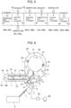
- the heated preform is molded into a bottle, and the summary of the heating apparatus for preforms and the heating method for preforms according to the present invention will be described by referring to FIG. 1 , and further, the details of the heating apparatus for preforms will be described by referring to FIG. 2 , FIG. 3 , and FIG. 4 .
- this Embodiment 1 it is possible to heat a preform to a temperature at which the preform is molded into a bottle, while maintaining the sterility of the sterilized preform.
- a heating apparatus 14 for preforms of the present invention is an apparatus that heats a preform 1 shown in FIG. 2 (A) to the temperature at which the preform 1 is molded into a bottle 2 shown in FIG. 2 (B) .
- the preform 1 is supplied by a preform supplying apparatus 3, and the supplied preform 1 is sterilized by a sterilizing unit 6.
- the sterilized preform 1 is heated by the heating apparatus 14 for preforms of the present invention to a temperature at which molding can be performed, and is passed to and received by an aseptic blow molding machine 20.
- the heating apparatus 14 for preforms includes a heating unit 19 and a driving unit 28, and the heating unit 19 at least includes a heater 15, a reflector 16, a spindle 27, an endless chain 12, and a pulley 13 for rotating the endless chain 12.
- the sterilized preform 1 is held by the spindle 27 provided to the endless chain 12 at regular intervals, heated by the heater 15 to a temperature at which molding can be performed while rotating, and conveyed to the next process while maintaining the sterility.
- the heating unit 19 of the heating apparatus 14 for preforms is covered by a heating unit chamber 18, and before operating the heating apparatus 14 for preforms, the inside of the heating unit chamber 18 is sterilized, an aseptic air is thereafter supplied into the heating unit chamber 18, and the inside of the heating unit chamber 18 is maintained at a positive pressure, and thus the preform 1 is heated to the temperature at which the preform 1 can be molded into the bottle 2 in a state where the sterility of the sterilized preform 1 is maintained.
- a sterilizing apparatus is provided in the heating unit chamber 18. Additionally, in order to hold the heating unit chamber 18 at a proper positive pressure, an aseptic air supplying apparatus 31 and an exhaust apparatus 37 are provided.
- the preform 1 heated by the heating apparatus 14 for preforms is molded into the bottle 2 by a blow molding unit 21, and the molded bottle 2 is sequentially conveyed to an inspection unit that inspects the bottle 2, a filling unit that fills the inspected bottle 2 with a sterilized content, and further a sealing unit that seals the bottle 2 filled with the content by a sterilized cap, and becomes an aseptic product filled with the content.
- a molding unit chamber 22 that covers the molding unit 21, an inspection unit chamber that covers the inspection unit, and a filling chamber that covers the filling unit and the sealing unit is also sterilized before the operation, and the inside of the chambers are maintained at a positive pressure with an aseptic air, thereby maintaining the sterility in the chambers.
- the pressure maintained at the positive pressure the pressure inside the filling unit chamber and the molding unit chamber 22 is set to be the highest pressure, and the pressure inside the inspection unit chamber and the heating unit chamber 18 is set lower than the highest pressure.
- the pressure in the filling unit chamber is 30 Pa to 150 Pa, and the pressure in the inspection unit chamber is set to 0 Pa to 30 Pa for exhausting.
- the pressure in the molding unit chamber is set to 30 Pa to 150 Pa, and the pressure in the heating unit chamber 18 is set to 0 Pa to 30 Pa.
- an exit chamber which is downstream from the sealing unit, discharges a product, and places an aseptic product on a conveyor and discharges the aseptic product to the outside of an aseptic filling machine, is a non-aseptic zone, and is exhausted and set to -30 Pa to 30 Pa.
- an aseptic air supplying apparatus is provided in each chamber in order to maintain the inside of the chamber at a positive pressure, it is not necessary to provide the aseptic air supplying apparatus in all of the molding unit chamber 22, the inspection unit chamber, and the filling unit chamber.
- the aseptic air supplied by the aseptic air supplying apparatus provided in the filling unit chamber may flow into the molding unit chamber 22 from the filling unit chamber, and the inside of the molding unit chamber 22 may be maintained at a positive pressure by the flowing aseptic air.
- an exhaust apparatus is provided in order to maintain the inside of a chamber at a proper pressure. However, this may also not be provided in all of the molding unit chamber 22, the inspection unit chamber, and the filling unit chamber.
- a sterilizing unit chamber 5 covering the sterilizing unit 6 that sterilizes the preform 1 is connected to an exhaust device, which is formed by a filter 25 that dissolves the disinfectant in the air in the sterilizing unit chamber 5, and a blower 26.
- an exhaust device which is formed by a filter 25 that dissolves the disinfectant in the air in the sterilizing unit chamber 5, and a blower 26.
- the preform 1 shown in FIG. 2 (A) is continuously conveyed with a preform supplying conveyor 4 at a desired speed by the preform supplying apparatus 3 shown in FIG. 1 to the sterilizing unit 6 for the preform 1.
- the preform 1 in the present Embodiment 1 is a test tube-like bottomed tubular body, and an opening 1a similar to that of the bottle 2 shown in FIG. 2(B) is given at the time of molding.
- a male screw is formed in this opening 1a simultaneously with the molding of the preform 1.
- a support ring 1b for conveyance is formed in a lower part of the opening 1a of the preform 1.
- the preform 1 or the bottle 2 is conveyed within the sterilizing unit 6 while being gripped by a gripper, which is not shown, via this support ring 1b.
- the preform 1 is molded by injection molding, compression molding, etc.
- the material of the preform 1 is formed by a thermoplastic resin, such as polyethylene terephthalate, polyethylene naphthalate, polypropylene, and polyethylene, and may be a single body or a combined body of these thermoplastic resins, or may include a recycled thermoplastic resin. Additionally, in order to give a barrier property, a thermoplastic resin such as an ethylene-vinyl alcohol-copolymer or polyamide having aromatic amine such as meta-xylene diamine as a monomer may be included as a layer or as a mixture,.
- a thermoplastic resin such as polyethylene terephthalate, polyethylene naphthalate, polypropylene, and polyethylene
- a thermoplastic resin such as an ethylene-vinyl alcohol-copolymer or polyamide having aromatic amine such as meta-xylene diamine as a monomer may be included as a layer or as a mixture,.
- the preform 1 is passed to and received by a preform sterilization wheel 7 by being gripped by the gripper provided in the preform sterilization wheel 7 at regular intervals from the preform supplying conveyor 4.
- the gas or mist of a disinfectant or a mixture of these is sprayed on the internal and external surfaces of the passed and received preform 1.
- the bacteria etc. adhering to the surfaces of the preform 1 are sterilized by the disinfectant sprayed on the preform 1.
- the gas or mist of the disinfectant or the mixture of these is a part of the gas of the disinfectant that is generated by a disinfectant gas generator 39 as shown in FIG. 4 described later, and that is turned into mist.
- the device by which the gas or mist of the disinfectant or the mixture of these is sprayed on the preform 1 is a nozzle that sprayed the gas or mist of the disinfectant or the mixture of these on the inner surface of the preform 1 by a nozzle, and the gas or mist of the disinfectant or the mixture of these that overflowed collides with an umbrella-like member provided in a nozzle tip, and contacts the outside surface of the preform 1.
- a nozzle may be provided separately, and the gas or mist of the disinfectant or a mixture of these may be directly sprayed on the outside surface of the preform 1. As long as the gas or mist of the disinfectant or the mixture of these can contact the internal and external surfaces of the preform 1, any device may be used.
- the preform 1 may be pre-heated by blowing a hot air on the preform 1, etc., immediately before spraying the gas or mist of the disinfectant or the mixture of these on the preform 1. This pre-heating can further increase the sterilizing effect for the preform 1.
- the disinfectant sprayed on the preform 1 prefferably includes at least hydrogen peroxide.
- a proper range for its content is 0.5 mass% to 65 mass%. When less than 0.5 mass%, the sterilizing power may be insufficient, and when exceeding 65 mass%, it becomes difficult to handle for safety reasons. Additionally, 0.5 mass% to 40 mass% is more preferably, and when 40 mass% or less, since it becomes more easy to handle, and the concentration becomes low, the residual among of hydrogen peroxide after sterilization can be reduced.
- the amount of the disinfectant made to adhere to the internal and external surfaces of the preform 1 is preferably in the range of 0.001 ⁇ L/cm 2 to 0.5 ⁇ L/cm 2 by using a hydrogen peroxide solution including 35 mass% of hydrogen peroxide.
- the adhering amount is less than 0.001 ⁇ L/cm 2 , a sufficient sterilizing effect cannot be obtained.
- this adhering amount exceeds 0.5 ⁇ L/cm 2 , in the case where the preform 1 is blow molded into the bottle 2, it becomes easy for defective molding to occur, such as bleaching, spots, wrinkles, and deformation.
- the adhering amount of the hydrogen peroxide solution including 35 mass% of hydrogen peroxide for the preform 1 is 0.002 ⁇ L/cm 2 to 0.4 ⁇ L/cm 2 .
- the disinfectant includes water
- the disinfectant may include one or two or more of alcohols such as methyl alcohol, ethyl alcohol, isopropyl alcohol, normal propyl alcohol, and butyl alcohol, ketones such as acetone, methyl ethyl ketone, and acetylacetone, glycol ether, etc.
- the disinfectant may include organic acids such as peracetic acid and acetic acid, chlorine compounds such as sodium hypochlorite, alkaline compounds such as sodium hydroxide and potassium hydroxide, compounds having the sterilizing effect such as nitric acid, ozone, acid water, etc., and additive agents such as cationic surfactant, nonionic surfactant, phosphoric acid compound, etc.
- organic acids such as peracetic acid and acetic acid
- chlorine compounds such as sodium hypochlorite
- alkaline compounds such as sodium hydroxide and potassium hydroxide
- compounds having the sterilizing effect such as nitric acid, ozone, acid water, etc.
- additive agents such as cationic surfactant, nonionic surfactant, phosphoric acid compound, etc.
- the preform 1 Before or after spraying the disinfectant on the preform 1, light including ultraviolet light or an electron beam having a wavelength of 100 nm to 380 nm may be irradiated to the preform 1, so as to improve the sterilizing effect. Additionally, the preform 1 may be sterilized by irradiating the light including ultraviolet light or the electron beam having the wavelength of 100 nm to 380 nm to the preform 1, without using the disinfectant.
- a disinfectant spraying nozzle is provided in a wall surface inside the sterilizing unit chamber 5, separately from a disinfectant gas spraying nozzle 8 for spraying the gas or mist of the disinfectant or a mixture of these on the preform 1. Additionally, a similar disinfectant spraying nozzle is also provided in order to sterilize a sterilizing unit chamber 5 side surface of the filter 25 contacting the sterilizing unit chamber 5.
- the preform 1 on which the gas or mist of the disinfectant or the mixture of these was sprayed is passed to and received by an air spraying wheel 9 as shown in FIG. 1 .
- An aseptic air is blown by an air blowing nozzle 10 on the preform 1 passed to and received by the wheel 9, while the preform 1 is conveyed by the gripper.
- the aseptic air is obtained by letting the air by a blower pass through an aseptic filter. Compressed air generated by a compressor may be used without using the blower.
- the disinfectant adhering to the surface of the preform 1 is activated, thereby sterilizing the bacteria, etc. that were not sterilized by spraying the disinfectant on the preform 1. Additionally, by blowing the air, the disinfectant adhering to the preform 1 is quickly removed from the surfaces of the preform 1. Since the disinfectant adhering to the preform 1 is removed from the preform 1 by blowing the aseptic air before entering the heating unit 19, various kinds of equipment such as a sealing member of the heating unit 19 is not damaged by the disinfectant. Additionally, the occurrence of defective molding of the bottle, such as bleaching, distortion, and molding unevenness, resulting from the adhesion of the disinfectant to the preform 1 is prevented.
- the aseptic air blown on the preform 1 may be at room temperature, or may be heated. However, it is preferable for the aseptic air to be heated, and by using the heated aseptic hot air, the dissolution of the disinfectant is facilitated, the sterilizing effect is increased, and the residual of the disinfectant is also reduced. It is preferable for the temperature of the aseptic hot air blown on the preform 1 to be set from 40°C to 140°C. When less than 40°C, the effect obtained by heating is less, and when the temperature of preform 1 exceeds 70°C, there is an inconvenience such as deformation of the opening 1a of the preform 1. Therefore, it is preferable for the temperature of the hot air not to exceed 140°C.
- the blowing of the aseptic air on the preform 1 is not essential, and may not be performed.
- the preform 1 is directly heated.
- the disinfectant is adhering to the internal and external surfaces of the preform 1 on which the gas of the disinfectant was sprayed, and when the preform 1 is heated to the molding temperature, the adhering disinfectant is activated, and the surface of the preform 1 is sterilized. Additionally, an excessive disinfectant is vaporized by heating.
- the preform 1 After blowing the aseptic air, the preform 1 is passed to and received by a wheel 11 shown in FIG. 1 .
- the preform 1 is released from the gripper, the spindle 27 is inserted into the opening 1a of the preform 1 as shown in FIG. 2(A) , and the preform 1 is conveyed into the heating unit 19 by the endless chain 12.
- the heating apparatus 14 for preforms consists of the heating unit 19 and the driving unit 28.
- the heating unit 19 at least includes a heater 15 for heating the preform 1, a reflector 16 for reflecting the heat of the heater 15 and efficiently heating the preform 1, the spindles 27 for holding and rotating the preform 1, the endless chain 12 for moving the spindles 27 on which the spindles 27 are provided at regular intervals, and pulleys 13a and 13b for rotating the endless chain 12.
- a heat insulating material 29 may be provided on the outer side of the heater 15.
- the driving unit 28 is provided with a motor, an operation transmitting device, etc. Since the equipment of the driving unit 28 requires a lubricant, and contamination is accumulated, it is difficult to maintain the sterility.
- Heater 15 is preferably a halogen lamp that emits an infrared light.
- a plurality of halogen lamps as heaters 15 are provided in parallel to be perpendicular to the axis direction of the preform 1.
- the preform 1 is heated by near infrared rays, infrared light, far-infrared rays emitted from the halogen lamps of the heaters 15.
- the heating temperature of the plurality of provided halogen lamps is controlled, and a temperature difference may be provided for the heating temperature in the axis direction of the preform 1.
- a plurality of units of halogen lamps are provided with respect to the moving direction of the preform 1 as shown in FIG. 1 .
- halogen lamp units 1 , 6 units on either column, 12 units in total are provided, the number of units can be arbitrarily determined.
- the temperature of these halogen lamp units is controlled, and may be set to be a high temperature at the beginning of heating, and to a low temperature at the end of heating.
- the preform 1 conveyed to the heating unit 19 is heated by infrared heating by the heaters 15 or other heating device to a temperature suitable for the later blow molding.
- This temperature is preferably 90°C to 130°C. Note that the temperature of the opening 1a of the preform 1 is suppressed to a temperature of 70°C or less, in order to prevent deformation, etc.
- an opening protection member 35 which is formed as a surface perpendicular to the axis direction of the preform 1, is provided under a support ring 1b of the preform 1.
- the opening protection member 35 prevents the infrared light, etc. that is emitted from the heaters 15 from reaching the opening 1a of the preform 1 more than necessary.
- a planar heat shield plate 36 may be provided at an angle of 90 degrees or less with respect to the axis direction of the preform 1.
- the sterilizing effect for the opening 1a may be degraded.
- a focus lamp that positively increases the temperature of the opening 1a may be provided in the heating unit 19, and the opening 1a may be heated by the focus lamp, so that the temperature of the opening 1a becomes 40°C to 70°C. In this manner, the sterilizing effect for the opening 1a can be improved, and the disinfectant adhering to the surface of the opening 1a can be vaporized and removed.
- the preform 1 is heated by the infrared light, etc. that is emitted from the heaters 15, the infrared light reaching behind the preform 1 without being absorbed by the preform 1 does not contribute to heating. Therefore, as shown in FIG. 3 , by providing the reflector 16 behind the preform 1, the infrared light, etc. reaching behind the preform 1 is reflected, and the heating of the preform 1 can be efficiently performed.
- the reflector 16 obtained by vapor-depositing or plating gold, silver, or aluminum on a metal is used. As long as it can reflect infrared light, etc., any kind of object may be used.
- the reflector 16 may be a flat surface, a curved surface, or a combination of a flat surface and a curved surface.
- the reflector 16 may be provided not only behind the preform 1, but also behind the heaters 15, so as to reflect the infrared light, etc. that is emitted behind the heaters 15.
- the spindle 27 is inserted into the opening 1a, and the preform 1 is conveyed within the heating unit 19 while being rotated.
- the preform 1 is supported by the spindle 27 by elastic deformation of an elastic body such as a rubber or a spring, when the lower part of the spindle 27 is inserted into the opening 1a.
- the spindle 27 is held by the endless chain 12.
- the endless chain 12 is rotated by the pulleys 13a and 13b. It is also possible to convey the preform 1 while rotating the preform 1 in an inverted state, by inserting a mandrel in the preform 1, instead of the spindle 27.
- the inside of the heating unit chamber 18 is sterilized before the heating apparatus 14 for preforms is operated. Therefore, a sterilizing apparatus is provided in the heating unit chamber 18.
- the sterilizing apparatus is a disinfectant nozzle 30 that sprays the gas or mist of the disinfectant or the mixture of these in the heating unit chamber, and the disinfectant gas generator 39 that generates the gas of the disinfectant.
- the disinfectant nozzles 30 are provided in wall surfaces of the heating unit chamber 18, and the gas or mist of the disinfectant or the mixture of these is sprayed into the heating unit chamber 18 from the disinfectant nozzles 30. From the disinfectant nozzles 30, the gas of the disinfectant generated by the disinfectant gas generator 39 shown in FIG. 4 is sprayed on the heating unit 19 in the heating unit chamber 18, and on the wall surfaces of the heating unit chamber 18.
- the disinfectant gas generator 39 includes a disinfectant supplying unit 40 that is a two-fluid spray nozzle supplying the disinfectant in drops, and a vaporizing unit 41 that heats the disinfectant supplied from this disinfectant supplying unit 40 to a dissolution temperature or less to vaporize the disinfectant.
- the disinfectant supplying unit 40 takes in the disinfectant and the compressed air from a disinfectant supply path 40a and a compressed air supply path 40b, respectively, and sprays the disinfectant into the vaporizing unit 41.
- the vaporizing unit 41 is a pipe that interposes a heater 41a between the inner and outer walls, and heats and vaporizes the disinfectant sprayed into this pipe.
- the gas of the vaporized disinfectant is ejected out to the outside of the vaporizing unit 41 from the lower end of the vaporizing unit 41.
- the vaporizing unit 41 may be heated by dielectric heating instead of the heater 41a.
- the pressure of the compressed air is adjusted in the range of 0.05 MPa to 0.6 MPa.
- the disinfectant may fall down by gravity, or a pressure may be applied to the disinfectant, and the supply amount can be set freely. For example, it is supplied in the range of 1 g/min. to 100 g/min.
- the sprayed disinfectant is vaporized by being heated from 140°C to 450°C.
- the gas of the ejected out disinfectant is mixed with the aseptic heated air blown into a conduit 42, so as to be the gas or mist of the disinfectant or the mixture of these, and is sprayed into the heating unit chamber 18 from the disinfectant nozzles 30.
- the spray amount of the gas or mist of the disinfectant or the mixture of these is arbitrary, the spray amount is determined by the amount of the disinfectant supplied to the disinfectant gas generator 39, and the spraying time.
- a plurality of disinfectant gas generators 39 may be provided.
- the disinfectant is a hydrogen peroxide solution
- a proper range for the concentration of hydrogen peroxide is 1 mg/L to 20 mg/L.
- the disinfectant may be turned into mist by the two-fluid spray, and may be sprayed into the heating unit chamber 18 from the disinfectant nozzles 30. In this case, the mist of the disinfectant may be sprayed toward the heaters 15, and the disinfectant may be vaporized with the heat of the heaters 15.
- the heating unit chamber 18 it is also possible to sterilize the inside of the heating unit chamber 18 while suppressing a variation in the disinfectant adhering amount to the apparatus of the heating unit 19, by operating the heating unit 19 in a state where the gas or mist of the disinfectant or the mixture of these is sprayed into the heating unit chamber 18. Specifically, by driving the spindles 27, the gripper, a cam roller, etc. in the heating unit chamber 18, it is possible to make the disinfectant adhere uniformly over the surfaces of these apparatuses.
- a disinfectant similar to that used for sterilizing the preform 1 can be used, and it is preferable to use a disinfectant that includes peracetic acid or hydrogen peroxide.
- a disinfectant that includes peracetic acid or hydrogen peroxide As for spraying of the disinfectant, different disinfectants may be sprayed for multiple times.
- the aseptic air is sprayed into the heating unit chamber 18.
- the aseptic air vaporizes and removes the disinfectant remaining in the heating unit chamber 18. Additionally, on this occasion, the vaporizing disinfectant may also exhibit the sterilizing effect.
- the aseptic air supplying apparatus 31 is provided in the lower part of the heating unit chamber 18.
- the aseptic air supplying apparatus 31 includes a blower 32 and an aseptic filter 34. Additionally, there are cases where the aseptic air is heated, and it is preferable to provide an aseptic air heating apparatus 33 between the blower 32 and the aseptic filter 34.
- the air by the blower 32 is heated by the aseptic air heating apparatus 33, and is sterilized by the aseptic filter 34, the air becomes an aseptic hot air and is blown into the heating unit chamber 18 from the lower part.
- the aseptic air may not be heated, when heated, the removal of the disinfectant is quickly performed, and the sterilizing effect of the disinfectant is also increased.
- the aseptic air may not be heated.
- the inner surface side of the aseptic filter 34 consisting of a HEPA filter, etc. is also sterilized, since the gas or mist of the disinfectant or the mixture of these is sprayed by the disinfectant nozzles 30.
- the aseptic air is blown into the heating unit chamber 18 from the lower part to the upper part. As shown in FIG. 3 , the aseptic air blown into from the lower part flows through the outer sides and the inner sides of the heaters 15 and the reflectors 16 toward the upper part.
- the flow rate of the aseptic air made to flow between the heater 15 and the reflector 16 may be controlled by adjusting the opening areas of a plate that is provided in the lower part of the preform 1. Additionally, the cooling effect by the flow of the aseptic air between the heater 15 and the reflector 16 may be suppressed by heating the aseptic air.
- the exhaust apparatus 37 is provided on the heating unit chamber 18, and the aseptic air is exhausted to the outside of the heating apparatus 14 for preforms, thereby properly maintaining the pressure in the heating unit chamber 18.
- the pressure in the heating unit chamber 18 is always measured by providing a pressure sensor 38 on the heating unit chamber 18. The blower 32 and the exhaust apparatus 37 are controlled according to the measured air pressure value, and the pressure in the heating unit chamber 18 is properly maintained.
- the heated preform 1 is released from the spindle 27, passed to and received by the gripper of the wheel 17, and further conveyed to the aseptic blow molding machine 20.
- the preform 1 is supplied to a mold 23 provided in the molding unit 21 of the aseptic blow molding machine 20, while maintaining the sterility.
- the inside of the molding unit chamber 22 is sterilized before the operation of the aseptic blow molding machine 20 with the disinfectant such as hydrogen peroxide solution, and during the operation, the aseptic air is supplied, and the sterility in the molding unit chamber 22 is maintained.
- the disinfectant such as hydrogen peroxide solution
- a disinfectant nozzle for spraying the disinfectant is provided in a wall surface of the molding unit chamber 22. Since the sterility of the molding unit chamber 22 is maintained, the molded bottle 2 also has the sterility.
- the preform 1 is passed to and received by the aseptic blow molding machine 20 from the wheel 17. Thereafter, a blow nozzle 43 is joined to the opening 1a of the preform 1, an extension rod 44 is guided by a hole provided in the blow nozzle 43 to be inserted into the preform 1, and simultaneously, an intermediate pressure air and a high pressure air are sequentially sent into the preform 1 by the operation of an electromagnetic valve of a valve block, which is not shown, and the preform 1 is molded into the bottle 2.
- the bottle 2 molded by the aseptic blow molding machine 20 is conveyed to the inspection unit chamber via a wheel 24.
- the bottle 2 that is inspected in the inspection unit chamber, and determined to have no defect is conveyed to the filling unit chamber, filled with a sterilized content, sealed by a sterilized cap, and taken out to a non-aseptic atmosphere as an aseptic product.
- the inspection may not be performed, in the case where a foreign matter, discoloration, a crack, etc. of the body of the bottle 2, a top panel of the opening 1a, the support ring 1b, a bottom part, etc. are inspected, and when it is determined to exceed the limit, the bottle 2 is discharged as the bottle 2 with a defect.
- the sterilizing unit that sterilizes the preform supplied from the preform supplying apparatus the heating unit that heats the sterilized preform to a temperature at which the preform is molded into a bottle, and the aseptic blow molding machine that molds the heated preform into the bottle is described, and referring to FIG. 2 , FIG. 7 , and FIG. 8 , each detail of the aseptic blow molding machine will be further described.
- the sterilized preform can be molded into an aseptic bottle.
- the aseptic blow molding machine 20 of the present invention is an apparatus that molds the preform 1 shown in FIG. 2 (A) into the bottle 2 shown in FIG. 2 (B) .
- the preform 1 is supplied by the preform supplying apparatus 3, and the supplied preform 1 is sterilized by the sterilizing unit 6.
- the sterilized preform 1 is heated to the molding temperature by the heating unit 19, and passed to and received by the aseptic blow molding machine 20 of the present invention.
- the aseptic blow molding machine 20 includes the molding unit 21 that molds the preform 1 into the bottle 2, and the molding unit 21 includes the mold 23 provided in the outer circumference of a molding wheel 47 at regular intervals.
- the preform 1 is molded into the bottle 2 having the shape of the mold 23, while being conveyed in the outer circumference of the molding wheel 47.
- the molded bottle 2 is conveyed to the next process, while maintaining the sterility.
- the molding unit 21 is covered by the molding unit chamber 22, and before operating the aseptic blow molding machine 20, the inside of the molding unit chamber 22 is sterilized, the aseptic air is thereafter supplied into the molding unit chamber 22, and the inside of the molding unit chamber 22 is maintained at a positive pressure. Accordingly, the aseptic bottle 2 can be obtained in a state where the sterility of the sterilized preform 1 is maintained.
- the molded bottle 2 is sequentially conveyed to the inspection unit that inspects the bottle 2, the filling unit that fills the inspected bottle 2 with a sterilized content, and further, the sealing unit that seals the bottle 2 filled with the content by a sterilized cap, and an aseptic product filled with the content is obtained.
- the inspection unit chamber that covers the inspection unit, and the filling unit chamber that covers the filling unit and the sealing unit are also sterilized before the operation, and the inside of the chambers is maintained at a positive pressure by the aseptic air. Accordingly, the sterility in the chambers is maintained.
- the filling unit chamber is set to have the highest pressure, and the more upstream the chamber is, such as the inspection unit chamber, and the molding unit chamber 22, the lower the pressure is set.
- the aseptic air is also supplied to the heating unit chamber 18, which is upstream of the molding unit chamber 22, in order to maintain the sterility during the operation.
- the pressure in the filling unit chamber is 30 Pa to 150Pa
- the pressure in the inspection unit chamber is set to 30 Pa to 50 Pa
- the pressure in the molding unit chamber 22 is set to 20 Pa to 30 Pa
- the pressure in the heating unit chamber 18 is set to 0 Pa to 20 Pa.
- the exit chamber that is downstream of the sealing unit, discharges a product, and places the aseptic product on a conveyor to discharge the product to the outside of the aseptic filling machine is set to 0 Pa to 20 Pa.
- the aseptic air supplying apparatus is provided in each of the chambers in order to maintain each of the chambers at a positive pressure, it is unnecessary to provide the aseptic air supplying apparatus in all of the chambers.
- the inside of the inspection unit chamber may be maintained at a positive pressure by the aseptic air that flows into the inspection unit chamber from the filling unit chamber.
- the inside of the molding unit chamber 22 may be maintained at a positive pressure by the aseptic air that flows into the molding unit chamber 22 from the filling unit chamber.
- an exhaust apparatus may be provided in each of the chambers. This may also not be provided in all of the chambers.
- the inside of the molding unit chamber 22 may be maintained at a proper pressure by the exhaust apparatus provided in the heating unit chamber 18.
- the inside of the inspection unit chamber is sterilized before the operation.
- a camera, a lamp, etc. which are the inspection equipment, may be sealed.
- the aseptic air is supplied, and the inside of the inspection unit chamber is maintained at a positive pressure.
- the sterilizing unit chamber 5 covering the sterilizing unit 6 that sterilizes the preform 1 is exhausted by the blower 26 as in Embodiment 1.
- the preform 1 shown in FIG. 2(A) is continuously conveyed by the preform supplying conveyor 4 at a desired speed from the preform supplying apparatus 3 shown in FIG. 6 to the sterilizing unit 6 for preforms 1.
- the preform 1 in the examples is the same as that in Embodiment 1.
- the preform 1 conveyed to the sterilizing unit 6 is sterilized as in Embodiment 1.
- the disinfectant used is the same as that in Embodiment 1.
- the gas or mist of the disinfectant or the mixture of these sprayed on the preform 1 is a part of the gas of the disinfectant that is generated by the disinfectant gas generator 39 as shown in FIG. 4 , and that is turned into mist.
- any kind of device may be used.
- pre-heating may be performed immediately before spraying the gas or mist of the disinfectant or the mixture of these on the preform 1.
- light including ultraviolet light or an electron beam, etc. may be irradiated to the preform 1 before or after spraying the disinfectant, so as to improve the sterilizing effect.
- the inside of the sterilizing unit chamber 5 is sterilized by a device of spraying, etc. the disinfectant such as hydrogen peroxide into the sterilizing unit chamber 5 before the operation.
- the preform 1 on which the gas or mist of the disinfectant or the mixture of these were sprayed is passed to and received by the air spraying wheel 9 as shown in FIG. 6 .
- the aseptic air is blown on the preform 1 that is passed to and received by the wheel 9.
- the preform 1 After blowing the aseptic air, the preform 1 is passed to and received by the wheel 11 shown in FIG. 1 .
- the preform 1 is released from the gripper, the spindle 27 is inserted into the opening 1a of the preform 1 as shown in FIG. 2(A) , and the preform 1 is conveyed to the heating unit 19 by the endless chain 12.
- the preform 1 conveyed to the heating unit 19 is heated to a temperature suitable for the subsequent blow molding.
- the heated preform 1 is released from the spindle 27, passed to and received by the gripper of the wheel 17, and conveyed to the molding wheel 47, while the aseptic air is blown by a preform aseptic air supply nozzle 46 from the opening 1a side.
- the preform 1 is supplied to the metal die 23 provided in the molding unit 21 of the aseptic blow molding machine 20 while maintaining the sterility.
- the aseptic air blown on the heated preform 1 in the wheel 17 may be hot air. By blowing the aseptic hot air, a decrease in the temperature of the preform 1 is prevented.
- a preform tunnel which is not shown, may be provided so as to surround the conveyance path for the preform 1.
- the preform tunnel covers the opening 1a of the preform 1 from its upper side, and a ceiling part is formed in a roof shape having an inclined surface.
- the preform aseptic air supply nozzle 46 that blows out the aseptic air toward the opening 1a of the preform 1 is provided in the ceiling part in pipe columns or in a slit shape. Accordingly, the aseptic air is efficiently supplied to the preform 1, and the preform 1 can be conveyed inside the heating unit chamber 18 while maintaining the sterility.
- the inside of the heating unit chamber 18 is sterilized before the operation, and during the operation, the aseptic air is supplied, and the sterility of the preform 1 is maintained.
- the blowing of the aseptic air on the preform 1 in the wheel 17 is for improving the sterility, and may not be performed.
- At least the infrared heater 15, the reflector 16 that reflects the heat by the infrared heater 15 for efficiently heating the preform 1, the endless chain 12, the pulleys 13a and 13b that actuate the spindle 27 and the endless chain 12 are provided inside the heating unit chamber 18, and the driving unit 28, etc. that rotates the pulleys 13a and 13b is provided outside of the heating unit chamber 18.
- the inside of the heating unit chamber 18 is sterilized with the disinfectant such as hydrogen peroxide before the operation of the heating apparatus 14, and the sterility inside the heating unit chamber 18 is maintained by supplying the aseptic air into the heating unit chamber 18 at the time of the operation.
- a nozzle for spraying the disinfectant is provided in a wall surface of the heating unit chamber 18.
- the aseptic blow molding machine 20 that molds the preform 1 into the bottle 2 at least includes the molding unit 21 and the driving unit 48 as shown in FIG. 7 .
- the molding unit 21 includes the mold 23, the blow nozzle 43, a valve block 45, and the extension rod 44.
- the mold 23 consists of the split molds 23a and 23b, and the bottom mold 23c.
- the driving unit 48 includes a motor, a hydraulic apparatus, an operation transmitting device, an air cylinder, etc. Since the equipment of the driving unit 48 requires a lubricant, and contamination is accumulated, it is difficult to maintain the sterility.
- the molding unit 21 is covered by the molding unit chamber 22. Since the inside of the molding unit chamber 22 is sterilized before the operation, the molding unit chamber 22 includes a sterilizing apparatus. Additionally, as shown in FIG. 7 , the molding unit chamber 22 is formed by a movable unit 50 that holds the molding unit 21, and isolates the molding unit 21 from the driving unit 48, and a fixed unit 51 that covers the molding unit 21 from the outside. The movable unit 50 is rotated about a rotating pipe 52 as the central axis. The molding unit 21 held by the movable unit 50 is also rotated, and with the rotation, the preform 1 is molded into the bottle 2 as shown in FIG. 2(B) .
- the preform 1 is passed to and received by the molding wheel 47 from the wheel 17. Thereafter, the blow nozzle 43 is joined to the opening 1a of the preform 1, the extension rod 44 is guided by the hole provided in the blow nozzle 43 to be inserted into the preform 1, and simultaneously, an intermediate pressure air P1 and a high pressure air P2 are sequentially sent into the preform 1 by the operation of the electromagnetic valve of the valve block 45, and the preform 1 is molded into the bottle 2. After the molding is completed, the extension rod 44 is lifted, and the high pressure air P2 remaining in the bottle 2 is returned to the intermediate pressure air P1 as a return air AR.
- the high pressure air P2 remaining in the bottle 2 may be exhausted to a non-aseptic atmosphere 53, without being returned as the intermediate pressure air P1.
- the mold 23 is opened, and the molded bottle 2 is gripped by the gripper of the wheel 24, and conveyed by a wheel outside the molding unit chamber 22.
- the molding of the preform 1 into the bottle 2 is performed by repeating the opening and closing of the mold 23 with the rotation of the movable unit 50 of the molding unit chamber 22 and the molding unit 21 held by the movable unit 50, the lowering and lifting of the extension rod 44, and the blowing of the intermediate pressure air P1 and the high pressure air P2 into the preform 1.
- the inside of the molding unit chamber 22 is maintained at an aseptic atmosphere at the time of the operation of the aseptic blow molding machine 20.
- the driving unit 48 is provided in the non-aseptic atmosphere 53.
- An aseptic atmosphere 54 and the non-aseptic atmosphere 53 are isolated by sealing the lower part of the movable unit 50 with a liquid seal apparatus 55 provided in the lower part of the movable unit 50.
- the liquid may be a liquid such as water, the liquid preferably includes a disinfectant, such as peracetic acid (as for the concentration included in the liquid, 100 ppm or more to 3000 ppm or less is preferable.), or hydrogen peroxide (preferably included in the liquid for 1 mass% or more to 36 mass% or less.).
- An end face of the movable unit 50 immersed in the liquid of the liquid seal apparatus 55 is provided so as not to contact a bottom part of the liquid seal apparatus 55.
- the liquid contacts both surfaces of the movable unit 50 that are immersed.
- the liquid surface height of the liquid on the side of the non-aseptic atmosphere 53 of the liquid seal apparatus 55 is higher than the liquid surface of the liquid on the side of the aseptic atmosphere 54.
- a liquid level gage may be provided in the liquid seal apparatus 55 so as to constantly monitor the liquid surface.
- the wall surface height on the side of the non-aseptic atmosphere 53 of the liquid seal apparatus 55 may be made lower than the wall surface height on the side of the aseptic atmosphere 54, so that the overflowed liquid is stored in a liquid reservoir 56, and discharged from a bottom part of the liquid reservoir 56.
- the intermediate pressure air P1 and the high pressure air P2 required for molding the preform 1 into the bottle 2 are supplied by hoses that are provided inside the rotating pipe 52 from the upper part of the blow molding machine 20.
- the rotating pipe 52 and the fixed unit 50 are joined by a rotary joint 57, so as to enable the rotation of the rotating pipe 52.
- the intermediate pressure air P1 and the high pressure air P2 are introduced into a high pressure air supplying apparatus 58 in the non-aseptic atmosphere 53 from the hoses in the rotating pipe 52 that passes through the inside of the aseptic atmosphere 54.
- the air introduced into the high pressure air supplying apparatus 58 is sterilized with the aseptic filter.
- the high pressure air supplying apparatus 58 is rotatable, since the intermediate pressure air P1 and the high pressure air P2 are supplied to the valve block 45, which is held by the movable unit 50, from the high pressure air supplying apparatus 58.
- the inside of the molding unit chamber 22 is sterilized before the operation of the aseptic blow molding machine 20. Therefore, as shown in FIG. 7 , disinfectant nozzles 59 are provided in the fixed unit 50 of the molding unit chamber 22. The gas or mist of the disinfectant or the mixture of these is sprayed from the disinfectant nozzles 59 into the molding unit chamber 22. A sterilizing apparatus for spraying the gas or mist of the disinfectant or the mixture of these from the disinfectant nozzles 59 is provided in the aseptic blow molding machine 20.
- the gas of the disinfectant generated by the disinfectant gas generator 39 shown in FIG. 4 is sprayed into the molding unit chamber 22 from the disinfectant nozzles 59.
- the disinfectant gas generator 39 and its operating condition are the same as those of Embodiment 1.
- the inside of the heating unit chamber 18 is maintained at a positive pressure by the aseptic air, the aseptic air heated by the infrared heater 15 of the heating unit 14, and exhausted from the heating unit chamber 18 may be used as an aseptic heated air to be blown into the conduit 42.
- the aseptic air After spraying the gas or mist of the disinfectant or the mixture of these into the molding unit chamber 22 from the disinfectant nozzles 59, the aseptic air is blown into the molding unit chamber 22.
- the aseptic air vaporizes and removes the disinfectant remaining in the molding unit chamber 22. Additionally, on this occasion, the vaporizing disinfectant may also exhibit the sterilizing effect.
- an aseptic air supplying apparatus 60 is provided on the fixed unit 51 of the molding unit chamber 22.
- the aseptic air supplying apparatus 60 includes a blower 61 and an aseptic filter 62. Additionally, it is preferable to provide an aseptic air heating apparatus 63 between the blower 61 and the aseptic filter 62, since there are also cases where the aseptic air is heated.
- the air from the blower 61 is heated by the aseptic air heating apparatus 63, and sterilized by the aseptic filter 62, the air becomes an aseptic hot air and is blown into the molding unit chamber 22.
- the aseptic air may not be heated, when heated, the removal of the disinfectant is quickly performed, and the sterilizing effect of the disinfectant is also increased.
- the heated aseptic air exhausted from the heating unit chamber 18 may be blown on the molding unit chamber 22.
- the inner surface side of the aseptic filter (HEPA) 62 is also sterilized by spraying the gas or mist of the disinfectant or the mixture of these by the disinfectant nozzles 59.
- the aseptic air that passed through the aseptic filter 62 may be blown into the molding unit chamber 22, and may be exhausted by the exhaust apparatus provided in the molding unit chamber 22. Additionally, the aseptic air may flow into the heating unit chamber 18 from the molding unit chamber 22, and may be exhausted by the exhaust apparatus provided in the heating unit chamber 18.
- the members exposed in the molding unit chamber 22 are sterilized by spraying the gas or mist of the disinfectant or the mixture of these into the molding unit chamber 22.
- the passages for the intermediate pressure air P1, the high pressure air P2 and the return air AR of the blow nozzle 43 and the valve block 45, which are not exposed, are not sterilized.
- the gas of the disinfectant generated by the disinfectant gas generator 39 may be introduced into these passages with the operation of molding, or a liquid disinfectant may be introduced to the inner surface of the preform 1 by a method of dropping, etc., the intermediate pressure P1 and the high pressure air P2 may be blown into the preform 1 from the blow nozzle 43 while the disinfectant remains on the inner surface of the preform 1, and the return air AR may be returned, so as to spread the disinfectant into the blow nozzle 43 or the valve block 45 to sterilize the passages.
- the gap between the rotary joint 57 and the rotating pipe 52 is sterilized by spraying the gas or mist of the disinfectant or the mixture of these from the disinfectant nozzles 59 before the operation. Further, the disinfectant is removed by blowing the aseptic hot air, and an aseptic condition is maintained by blowying the aseptic air into the molding unit chamber 22 also at the time of the operation of the aseptic blow molding machine 20. Additionally, sterilization by steam may be concurrently used for sterilization before the operation.
- the extension rod 44 and the mold 23 are exposed in the molding unit chamber 22, the extension rod 44 and the mold 23 are sterilized by the gas or mist of the disinfectant or the mixture of these sprayed from the disinfectant nozzles 59.
- the extension rod 44 is held by an extension rod holding member 64.
- the operation of lifting and lowering the extension rod 44 is performed by operating the extension rod holding member 64.
- the extension rod holding member 64 is operated up and down by the movement of an extension rod holding member motion axis 64a.
- the extension rod holding member 64 is operated by rotating the extension rod holding member motion axes 64a by a servomotor provided in the driving unit 48, or by coupling the extension rod holding member motion axis 64a to a pneumatic cylinder.
- the pneumatic cylinder it is necessary to sterilize the inside of the cylinder by introducing the gas of the disinfectant into the cylinder, etc., and to make the air for generating a pressure pass through an aseptic filter to sterilize the air. Additionally, the axis that goes in and out of the pneumatic cylinder may be protected with a bellows.
- the sterility of extension rod 44 may be maintained by surrounding the extension rod 44 that slides by a chamber, and supplying the gas or mist of the disinfectant or the mixture of these into the chamber.
- the disinfectant supplied into the chamber at the time of the operation may be exhausted from the upper part of the chamber, so that the disinfectant does not flow into the mold 23 or to the bottle 2 side.
- the concentration of the hydrogen peroxide in the gas of the disinfectant is preferably 0.1 mg/L to 10 mg/L.
- the gas concentration of the disinfectant including hydrogen peroxide in order to prevent the disinfectant from condensing on an inner surface of the chamber, a surface of the extension rod 44, etc., it is desirable to heat the gas of the disinfectant to the dew point of the gas of the disinfectant or higher.
- the extension rod 44 may not be directly held by the extension rod holding member 64, and may be lifted and lowered by using a magnetic body.
- the extension rod 44 coupled to an internal magnetic body 66 can also be lifted or lowered by providing an external magnetic body 65 via an external magnetic body holding member 67 that is coupled to an extension rod holding member motion axis 64a, and operating the external magnetic body 65.
- the external magnetic body 65 and the internal magnetic body 66 are isolated by an isolation pipe 68 made of a non-magnetic body, and the external magnetic body 65 slides on the outside of the isolation pipe 68, and the internal magnetic body 66 slides on the inside of isolation pipe 68.
- the external magnetic body holding member 67 By moving the external magnetic body holding member 67, the external magnetic body 65 is operated up and down.
- FIG. 8(A) shows the state where the extension rod 44 is lifted
- FIG. 8(B) shows the state where the extension rod 44 is lowered, and inserted into the preform 1.
- the external magnetic body holding member 67 is operated by rotating the extension rod holding member motion axis 64a, or by coupling the extension rod holding member motion axis 64a to the pneumatic cylinder.
- the upper part of the isolation pipe 68 is opened, and the extension rod 44 is sterilized by the gas or mist of the disinfectant or the mixture of these in the sterilization before the operation.
- the gas or mist of the disinfectant or the mixture of these can flow into the lower part of the isolation pipe 68, and the lower part of the internal magnetic body 66 can also be sterilized.
- the bottle 2 molded by the aseptic blow molding machine 20 of the present invention is conveyed to the inspection unit chamber via the wheel 24.
- the bottle 2 that is inspected in the inspection unit chamber, and determined to have not defect is conveyed to the filling unit chamber, filled with a sterilized contents, sealed with sterilized cap, and taken out to a non-aseptic atmosphere as an aseptic product.
- the inspection may not be performed, in the case where a foreign matter, discoloration, a crack, etc. of the body of the bottle 2, the top panel of the opening la, the support ring 1b, the bottom part, etc. are inspected, and when it is determined to exceed the limit, the bottle 2 is discharged.
Description
- The present invention relates to a heating apparatus and a heating method for preforms for sterilizing a preform, and heating the sterilized preform in an aseptic atmosphere.
- Conventionally, a sterilizing method is proposed that applies a disinfectant to a preform while continuously conveying the preform, directly introduces the preform into a heating furnace, heats the preform to a temperature for molding the preform into a container in the heating furnace, and simultaneously performs drying and activation of the disinfectant applied to the preform by this heating (Patent Literature 1). In this case, the preform is sterilized in the heating furnace since the disinfectant is activated in the heating furnace. However, there is no description about a countermeasure against the possibility that bacteria, etc. existing in the heating furnace adhere to the preform after the activation of the disinfectant is completed. Additionally, there is no description about a method or an apparatus for maintaining the sterility when molding the preform.
- Additionally, a drink filling method is proposed that sprays mist or gas of a hydrogen peroxide solution on a preform, further heats the preform to a molding temperature, molds the preform that reached the molding temperature into a bottle within a blow molding die that is similarly continuously conveyed, removes the bottle from the blow molding die, and thereafter fills the bottle with a drink and seals the bottle with a lid (
Patent Literatures 2 and 3). In these Patent Literatures, there is a description of covering a heating unit and a molding unit, sterilizing the inside of a covered chamber before the operation of the heating unit and the molding unit, and supplying an aseptic air into the chamber at the time of the operation. However, there is no sufficient description about securing and maintaining the sterility in the heating unit that heats the preform. Additionally, there is no description about securing and maintaining the sterility in the molding unit that molds the preform into a bottle. - On the other hand, a method is also proposed that performs ultraviolet irradiation in the heating unit that heats the preform, so as to prevent contamination of the preform in the heating unit (Patent Literature 4).
- Further, a method and an apparatus are proposed that sterilize the inner surface of a mold that molds a preform into a bottle (Patent Literature 5). Additionally, it is also proposed to provide a mold, a blow nozzle, and an extension rod in a clean room (Patent Literature 6). However, there is a possibility that sterilization of the mold inner surface is complicated, and durability is insufficient since a bellows is used for maintaining the sterility of the extension rod.
- Additionally, an apparatus and the like are proposed that set a blow nozzle and a mold of a molding machine in an aseptic atmosphere, and set the other in a non-aseptic atmosphere, sterilize a chamber in which an extension rod in the non-aseptic atmosphere is moved, so as to secure the sterility of the extension rod (
Patent Literatures 7 and 8). However, a sterilization mechanism for the extension rod is complicated, and an opening of the molded bottle is directed downward, and it is difficult to direct the opening upward. Additionally, when the opening of the bottle is directed downward, a conveying apparatus becomes complicated, and it is necessary to provide the equipment for reversing the bottle. - In the document
US 2009/317506 A1 , a sterilizing apparatus is described. The apparatus comprises a transfer unit that transfers a preform having adsorbed a sterilizer or a bottle from a supplying stage of the preform to a molding stage of the bottle, a heating furnace that heats the preform to a temperature for a blow-molding treatment to activate the sterilizer adsorbed by the preform, thereby sterilizing the preform, and a mold that blow-molds the preform into the bottle by air. -
Document EP 3 069 847 A1 discloses a heating apparatus for preforms, the heating apparatus comprising at least a heating unit that heats a preform to a temperature for blow molding of the preform into a bottle, and a driving unit that drives the heating unit, wherein the heating unit includes at least a heater, a reflector, a spindle, an endless chain, and a pulley for rotating the endless chain, the heating unit is covered by a heating unit chamber, and a sterilizing apparatus that sterilizes an inside and an inner surface of the heating unit chamber is provided. -
- Patent Literature 1:
Japanese Patent Laid-Open No. 2008-183899 - Patent Literature 2:
Japanese Patent Laid-Open No. 2013-35562 - Patent Literature 3:
Japanese Patent Laid-Open No. 2015-116814 - Patent Literature 4:
Japanese Patent Laid-Open No. 2010-507503 - Patent Literature 5:
Japanese Patent Laid-Open No. 2011-51337 - Patent Literature 6:
Japanese Patent Laid-Open No. 2012-500134 - Patent Literature 7:
Japanese Patent Laid-Open No. 2010-264753 - Patent Literature 8:
Japanese Patent Laid-Open No. 2013-504456 - Conventionally, an aseptic filling machine for bottles molds a preform into a bottle, and sterilizes the molded bottle. However, since a large quantity of disinfectant is required, and the apparatus becomes excessively large, an aseptic filling machine that performs sterilization at the stage of a preform is becoming widely used. However, it is necessary to convey a bottle while maintaining the sterility until the molded bottle is filled with a content, after the sterilization is performed at the stage of the preform, and the preform is molded into the bottle. Especially, it is important to secure the sterility in a heating process that heats the sterilized preform for molding the preform into a bottle, and in a molding step that molds the preform into a bottle, and this has been a problem.
- Even if the bacteria, etc. adhering to the internal and external surfaces of a preform are sterilized, in order to mold the preform into a bottle, the preform must be heated to the temperature at which molding can be performed. Conventionally, in order to prevent a foreign matter from being mixed into the inside of the preform in this process, heating was performed with the opening of the preform directed downward, and the subsequent blow molding of the bottle was also performed with the opening directed downward. However, the bottle must be reversed in order to direct the opening upward, so as to fill the bottle with content after the bottle is molded. In order to avoid this, heating and molding are performed with the opening of the preform directed upward. Whether the opening of the preform is directed downward or upward, there is a high possibility that not only a foreign matter but also bacteria, etc. that cannot be viewed exist in the heating unit of the preform, and there is a possibility that bacteria, etc. may adhere to the internal and external surfaces of the preform after sterilization in the heating unit and the molding part. In the case where the bacteria, etc. adhere to the inside, the sterility of the content is lost, and in the case where the bacteria, etc. adhere to the outside, when the adhering bacteria, etc. fall in a filling unit, the bacteria, etc. will invade into the filling unit. As a result, the sterility of the filling unit is lost, the bacteria, etc. will invade into the inside of a bottle, and the sterility of a product will be lost.
- In
Patent Literature 2, there is a description about integrally forming the heating unit that heats the sterilized preform and the molding unit that molds the preform into a bottle after heating, sterilizing the molding unit before the operation, and maintaining the sterility of the molding unit at the time of operation. However, there isn't sufficient description about the sterilization of the heating unit before the operation, and maintaining the sterility of the heating unit at the time of operation. Additionally, inPatent Literature 4, there is a description that an atmosphere is also sterilized by filtering the circulating air in the heating unit at the time of operation, and by performing ultraviolet irradiation to the circulating air. However, there is no description about the sterilization of the heating unit before the operation.Patent Literature 4 does not prevent contamination by bacteria, etc. of the preform in the heating unit, but it is the proposal of sterilizing bacteria, etc. that contaminate the preform in the heating unit during the operation. This cannot fully sterilize the bacteria, etc. that exist in the heating unit before the operation. - As described above, a heating apparatus and a heating method for preforms are demanded that maintain the sterility of the sterilized preform, and heat to the temperature at which the preform can be molded into a bottle.
- The molding machine and the molding method that mold the sterilized preform into a bottle are proposed by
Patent Literature 5,Patent Literature 6,Patent Literature 7, andPatent Literature 8. However, because of the reasons described in Background Art, all of these are insufficient as a technology for securing the sterility of the molding unit. That is, an aseptic blow molding machine and an aseptic blow molding method are desired that can mold the sterilized preform in an aseptic atmosphere, and takes out a bottle from the molding machine in a state where the sterility of the bottle is maintained. - The present invention aims at providing a heating apparatus and a heating method for preforms that can heat a sterilized preform in an aseptic atmosphere, and convey the preform to a molding unit that molds the preform into a bottle while maintaining the sterility of the preform.
- A heating apparatus for preforms according to the present invention is a heating apparatus for preforms, the heating apparatus including at least a heating unit that heats a preform to a temperature for blow molding of the preform into a bottle, and a driving unit that drives the heating unit, wherein the heating unit includes at least a heater, a reflector, a spindle, an endless chain, and a pulley for rotating the endless chain, the heating unit is covered by a heating unit chamber, and a sterilizing apparatus that sterilizes an inside and an inner surface of the heating unit chamber is provided, an aseptic air supplying apparatus that supplies an aseptic air into the heating unit chamber is provided so as to supply the aseptic air from a lower part of the heating unit chamber.
- Additionally, in the heating apparatus for preforms according to the present invention, the heating unit chamber that holds the heating unit, and covers the heating unit from the open air.
- Additionally, in the heating apparatus for preforms according to the present invention, it is preferable that an aseptic air heating apparatus is provided in the aseptic air supplying apparatus.
- Additionally, in the heating apparatus for preforms according to the present invention, it is preferable that a disinfectant gas generator that generates a gas of a disinfectant is provided in the sterilizing apparatus.
- A heating method for preforms according to the present invention is a heating method for preforms using a heating apparatus for preforms, the heating apparatus comprising at least a heating unit that heats a preform to a temperature for blow molding of the preform into a bottle, and a driving unit that drives the heating unit, wherein the heating unit includes at least a heater, a reflector, a spindle, an endless chain, and a pulley for rotating the endless chain, the heating unit is covered by a heating unit chamber, and wherein after the heating unit chamber is sterilized by spraying a gas or mist of a disinfectant or a mixture of these into the heating unit chamber, an aseptic air is supplied into the heating unit chamber from a lower part of the heating unit chamber, the inside of the heating unit chamber is held in the aseptic atmosphere and a sterilized preform is heated by making the inside of the heating unit chamber into an aseptic atmosphere.
- An aseptic blow molding machine according to an example useful to understand the present invention is an aseptic blow molding machine including at least a molding unit that performs blow molding of a preform into a bottle, and a driving unit that drives the molding unit, wherein the molding unit includes at least a mold, a blow nozzle, a valve block, and an extension rod, the molding unit is covered by a molding unit chamber, and a sterilizing apparatus that sterilizes an inside and an inner surface of the molding unit chamber is provided.
- Additionally, in the aseptic blow molding machine according to the example, it is preferable that the molding unit chamber consists of a movable unit that holds the molding unit and covers the driving unit, and a fixed unit that covers the molding unit from an outside air.
- Additionally, in the aseptic blow molding machine according to the example, it is preferable that a liquid seal apparatus that seals the movable unit and the fixed unit is provided.
- Additionally, in the aseptic blow molding machine according to the example, it is preferable that a high pressure air supplying apparatus is provided that is in the molding unit chamber, and that supplies a high pressure air to the valve block from an outside of the molding unit chamber through an inside of a rotating tube.
- Additionally, in the aseptic blow molding machine according to the example, it is preferable that an aseptic air supplying apparatus that supplies an aseptic air to the molding unit chamber is provided.
- Additionally, in the aseptic blow molding machine according to the example, it is preferable that the aseptic air supplying apparatus is provided on the molding unit chamber.
- Additionally, in the aseptic blow molding machine according to the example, it is preferable that an aseptic air heating apparatus is provided in the aseptic air supplying apparatus.
- Additionally, in the aseptic blow molding machine according to the example, it is preferable that a disinfectant gas generator that generates a gas of a disinfectant is provided in the sterilizing apparatus.
- An aseptic blow molding method according to another example usefule to understand the present invention is an aseptic blow molding method using a blow molding machine including at least a molding unit that performs blow molding of a preform into a bottle, and a driving unit that drives the molding unit, wherein the molding unit includes at least a mold, a blow nozzle, a valve block, and an extension rod, the molding unit is covered by a molding unit chamber, and a sterilized preform is molded into the bottle by making the inside of the molding unit chamber into an aseptic atmosphere.
- Additionally, in the aseptic blow molding method according to the example, it is preferable that the molding unit chamber is sterilized by spraying a gas or mist of a disinfectant or a mixture of these into the molding unit chamber.
- Additionally, in the aseptic blow molding method according to the example, it is preferable that an aseptic air is supplied into the molding unit chamber, and the inside of the molding unit chamber is maintained in the aseptic atmosphere.
- According to the heating apparatus and the heating method for preforms of the present invention, it is possible to heat the preform and to mold the preform into an aseptic bottle, while maintaining the sterility of the sterilized preform. Additionally, according to the aseptic blow molding machine and the aseptic molding method of the examples, it is possible to mold an aseptic bottle while maintaining the sterility of the sterilized preform. Further, even with an aseptic filling machine including a sterilizing unit that sterilizes the preform, it is possible to secure a high sterility by including the heating apparatus for preforms of the present invention and the exemplary aseptic blow molding machine.
-
- [
FIG. 1] FIG. 1 is a plan view showing the outline of an example of a blow molding machine that incorporates a heating apparatus for preforms according to an embodiment of the present invention, and that molds a preform into a bottle. - [
FIG. 2] FIG. 2 is a diagram showing a process of heating and molding a preform, in whichFIG. 2(A) shows a heating process of the preform according to an embodiment of the present invention, andFIG. 2(B) shows an exemplary blow molding process of the heated preform into a bottle. - [
FIG. 3] FIG. 3 is a cross-sectional view showing the outline of an example of a heating apparatus for preforms according to an embodiment of the present invention. - [
FIG. 4] FIG. 4 is a diagram showing a disinfectant gas generator provided in a sterilizing apparatus according to an embodiment of the present invention. - [
FIG. 5] FIG. 5 is a diagram showing the flow and pressure of an aseptic air in each chamber of an aseptic filling machine incorporating a heating apparatus for preforms according to an embodiment of the present invention. - [
FIG. 6] FIG. 6 is a plan view showing the outline of an example of an apparatus that molds a preform into a bottle. - [
FIG. 7] FIG. 7 is a cross-sectional view showing the outline of an example of an aseptic blow molding machine. - [
FIG. 8] FIG. 8 is a diagram showing the operation of an extension rod of an exemplary aseptic blow molding machine, in whichFIG. 8(A) shows the state where the extension rod is lifted, andFIG. 8(B) shows the state where the extension rod is lowered. - Modes for carrying out the present invention will be described below with reference to the drawings. The description will be given by assuming an embodiment of the present invention related to a heating apparatus and a heating method for preforms as
Embodiment 1, and assuming examples useful to understand the present invention related to an aseptic blow molding machine and an aseptic blow molding method as Examples useful to understand the present invention. - A preform supplied from a preform supplying apparatus is sterilized in a sterilizing unit, and the sterilized preform is heated to the temperature at which the preform can be molded into a bottle, by a heating apparatus for preforms according to the present invention. The heated preform is molded into a bottle, and the summary of the heating apparatus for preforms and the heating method for preforms according to the present invention will be described by referring to
FIG. 1 , and further, the details of the heating apparatus for preforms will be described by referring toFIG. 2 ,FIG. 3 , andFIG. 4 . According to thisEmbodiment 1, it is possible to heat a preform to a temperature at which the preform is molded into a bottle, while maintaining the sterility of the sterilized preform. - A
heating apparatus 14 for preforms of the present invention is an apparatus that heats apreform 1 shown inFIG. 2 (A) to the temperature at which thepreform 1 is molded into abottle 2 shown inFIG. 2 (B) . As shown inFIG. 1 , thepreform 1 is supplied by apreform supplying apparatus 3, and the suppliedpreform 1 is sterilized by a sterilizingunit 6. The sterilizedpreform 1 is heated by theheating apparatus 14 for preforms of the present invention to a temperature at which molding can be performed, and is passed to and received by an asepticblow molding machine 20. Theheating apparatus 14 for preforms according to the embodiment of the present invention includes aheating unit 19 and a drivingunit 28, and theheating unit 19 at least includes aheater 15, areflector 16, aspindle 27, anendless chain 12, and a pulley 13 for rotating theendless chain 12. The sterilizedpreform 1 is held by thespindle 27 provided to theendless chain 12 at regular intervals, heated by theheater 15 to a temperature at which molding can be performed while rotating, and conveyed to the next process while maintaining the sterility. - The
heating unit 19 of theheating apparatus 14 for preforms is covered by aheating unit chamber 18, and before operating theheating apparatus 14 for preforms, the inside of theheating unit chamber 18 is sterilized, an aseptic air is thereafter supplied into theheating unit chamber 18, and the inside of theheating unit chamber 18 is maintained at a positive pressure, and thus thepreform 1 is heated to the temperature at which thepreform 1 can be molded into thebottle 2 in a state where the sterility of the sterilizedpreform 1 is maintained. - In order to sterilize the inside of the
heating unit chamber 18, a sterilizing apparatus is provided in theheating unit chamber 18. Additionally, in order to hold theheating unit chamber 18 at a proper positive pressure, an asepticair supplying apparatus 31 and anexhaust apparatus 37 are provided. - The
preform 1 heated by theheating apparatus 14 for preforms is molded into thebottle 2 by ablow molding unit 21, and the moldedbottle 2 is sequentially conveyed to an inspection unit that inspects thebottle 2, a filling unit that fills the inspectedbottle 2 with a sterilized content, and further a sealing unit that seals thebottle 2 filled with the content by a sterilized cap, and becomes an aseptic product filled with the content. - The inside of a
molding unit chamber 22 that covers themolding unit 21, an inspection unit chamber that covers the inspection unit, and a filling chamber that covers the filling unit and the sealing unit is also sterilized before the operation, and the inside of the chambers are maintained at a positive pressure with an aseptic air, thereby maintaining the sterility in the chambers. As for the pressure maintained at the positive pressure, the pressure inside the filling unit chamber and themolding unit chamber 22 is set to be the highest pressure, and the pressure inside the inspection unit chamber and theheating unit chamber 18 is set lower than the highest pressure. - For example, as shown in
FIG. 5 , the pressure in the filling unit chamber is 30 Pa to 150 Pa, and the pressure in the inspection unit chamber is set to 0 Pa to 30 Pa for exhausting. Additionally, the pressure in the molding unit chamber is set to 30 Pa to 150 Pa, and the pressure in theheating unit chamber 18 is set to 0 Pa to 30 Pa. Further, an exit chamber, which is downstream from the sealing unit, discharges a product, and places an aseptic product on a conveyor and discharges the aseptic product to the outside of an aseptic filling machine, is a non-aseptic zone, and is exhausted and set to -30 Pa to 30 Pa. - Although an aseptic air supplying apparatus is provided in each chamber in order to maintain the inside of the chamber at a positive pressure, it is not necessary to provide the aseptic air supplying apparatus in all of the
molding unit chamber 22, the inspection unit chamber, and the filling unit chamber. For example, the aseptic air supplied by the aseptic air supplying apparatus provided in the filling unit chamber may flow into themolding unit chamber 22 from the filling unit chamber, and the inside of themolding unit chamber 22 may be maintained at a positive pressure by the flowing aseptic air. In order to maintain the inside of a chamber at a proper pressure, an exhaust apparatus is provided. However, this may also not be provided in all of themolding unit chamber 22, the inspection unit chamber, and the filling unit chamber. - A sterilizing
unit chamber 5 covering the sterilizingunit 6 that sterilizes thepreform 1 is connected to an exhaust device, which is formed by afilter 25 that dissolves the disinfectant in the air in the sterilizingunit chamber 5, and ablower 26. By exhausting the air in the sterilizingunit chamber 5 during the operation of the sterilizingunit 6, the inflow of the disinfectant to theadjacent heating unit 19 can be prevented. As shown inFIG. 5 , since the sterilizingunit chamber 5 is exhausted, the pressure in the sterilizingunit chamber 5 is set to -30 Pa to 0 Pa. - First, the
preform 1 shown inFIG. 2 (A) is continuously conveyed with apreform supplying conveyor 4 at a desired speed by thepreform supplying apparatus 3 shown inFIG. 1 to the sterilizingunit 6 for thepreform 1. - The
preform 1 in thepresent Embodiment 1 is a test tube-like bottomed tubular body, and anopening 1a similar to that of thebottle 2 shown inFIG. 2(B) is given at the time of molding. A male screw is formed in thisopening 1a simultaneously with the molding of thepreform 1. Additionally, asupport ring 1b for conveyance is formed in a lower part of theopening 1a of thepreform 1. Thepreform 1 or thebottle 2 is conveyed within the sterilizingunit 6 while being gripped by a gripper, which is not shown, via thissupport ring 1b. Thepreform 1 is molded by injection molding, compression molding, etc. The material of thepreform 1 is formed by a thermoplastic resin, such as polyethylene terephthalate, polyethylene naphthalate, polypropylene, and polyethylene, and may be a single body or a combined body of these thermoplastic resins, or may include a recycled thermoplastic resin. Additionally, in order to give a barrier property, a thermoplastic resin such as an ethylene-vinyl alcohol-copolymer or polyamide having aromatic amine such as meta-xylene diamine as a monomer may be included as a layer or as a mixture,. - The
preform 1 is passed to and received by apreform sterilization wheel 7 by being gripped by the gripper provided in thepreform sterilization wheel 7 at regular intervals from thepreform supplying conveyor 4. In order to sterilize thepreform 1, the gas or mist of a disinfectant or a mixture of these is sprayed on the internal and external surfaces of the passed and receivedpreform 1. The bacteria etc. adhering to the surfaces of thepreform 1 are sterilized by the disinfectant sprayed on thepreform 1. - The gas or mist of the disinfectant or the mixture of these is a part of the gas of the disinfectant that is generated by a
disinfectant gas generator 39 as shown inFIG. 4 described later, and that is turned into mist. The device by which the gas or mist of the disinfectant or the mixture of these is sprayed on thepreform 1 is a nozzle that sprayed the gas or mist of the disinfectant or the mixture of these on the inner surface of thepreform 1 by a nozzle, and the gas or mist of the disinfectant or the mixture of these that overflowed collides with an umbrella-like member provided in a nozzle tip, and contacts the outside surface of thepreform 1. Additionally, a nozzle may be provided separately, and the gas or mist of the disinfectant or a mixture of these may be directly sprayed on the outside surface of thepreform 1. As long as the gas or mist of the disinfectant or the mixture of these can contact the internal and external surfaces of thepreform 1, any device may be used. - Further, the
preform 1 may be pre-heated by blowing a hot air on thepreform 1, etc., immediately before spraying the gas or mist of the disinfectant or the mixture of these on thepreform 1. This pre-heating can further increase the sterilizing effect for thepreform 1. - It is preferable for the disinfectant sprayed on the
preform 1 to include at least hydrogen peroxide. A proper range for its content is 0.5 mass% to 65 mass%. When less than 0.5 mass%, the sterilizing power may be insufficient, and when exceeding 65 mass%, it becomes difficult to handle for safety reasons. Additionally, 0.5 mass% to 40 mass% is more preferably, and when 40 mass% or less, since it becomes more easy to handle, and the concentration becomes low, the residual among of hydrogen peroxide after sterilization can be reduced. - When the disinfectant sprayed on the
preform 1 includes hydrogen peroxide, the amount of the disinfectant made to adhere to the internal and external surfaces of thepreform 1 is preferably in the range of 0.001 µL/cm2 to 0.5 µL/cm2 by using a hydrogen peroxide solution including 35 mass% of hydrogen peroxide. When the adhering amount is less than 0.001 µL/cm2, a sufficient sterilizing effect cannot be obtained. Additionally, when this adhering amount exceeds 0.5 µL/cm2, in the case where thepreform 1 is blow molded into thebottle 2, it becomes easy for defective molding to occur, such as bleaching, spots, wrinkles, and deformation. More preferably, the adhering amount of the hydrogen peroxide solution including 35 mass% of hydrogen peroxide for thepreform 1 is 0.002 µL/cm2 to 0.4 µL/cm2. - Additionally, though the disinfectant includes water, the disinfectant may include one or two or more of alcohols such as methyl alcohol, ethyl alcohol, isopropyl alcohol, normal propyl alcohol, and butyl alcohol, ketones such as acetone, methyl ethyl ketone, and acetylacetone, glycol ether, etc.
- Further, the disinfectant may include organic acids such as peracetic acid and acetic acid, chlorine compounds such as sodium hypochlorite, alkaline compounds such as sodium hydroxide and potassium hydroxide, compounds having the sterilizing effect such as nitric acid, ozone, acid water, etc., and additive agents such as cationic surfactant, nonionic surfactant, phosphoric acid compound, etc.
- Before or after spraying the disinfectant on the
preform 1, light including ultraviolet light or an electron beam having a wavelength of 100 nm to 380 nm may be irradiated to thepreform 1, so as to improve the sterilizing effect. Additionally, thepreform 1 may be sterilized by irradiating the light including ultraviolet light or the electron beam having the wavelength of 100 nm to 380 nm to thepreform 1, without using the disinfectant. - The inside of the sterilizing
unit chamber 5 is sterilized before the operation by a device of spraying, etc. the disinfectant such as hydrogen peroxide solution. Therefore, a disinfectant spraying nozzle is provided in a wall surface inside the sterilizingunit chamber 5, separately from a disinfectantgas spraying nozzle 8 for spraying the gas or mist of the disinfectant or a mixture of these on thepreform 1. Additionally, a similar disinfectant spraying nozzle is also provided in order to sterilize a sterilizingunit chamber 5 side surface of thefilter 25 contacting the sterilizingunit chamber 5. - The
preform 1 on which the gas or mist of the disinfectant or the mixture of these was sprayed is passed to and received by anair spraying wheel 9 as shown inFIG. 1 . An aseptic air is blown by anair blowing nozzle 10 on thepreform 1 passed to and received by thewheel 9, while thepreform 1 is conveyed by the gripper. The aseptic air is obtained by letting the air by a blower pass through an aseptic filter. Compressed air generated by a compressor may be used without using the blower. - By blowing the aseptic air, the disinfectant adhering to the surface of the
preform 1 is activated, thereby sterilizing the bacteria, etc. that were not sterilized by spraying the disinfectant on thepreform 1. Additionally, by blowing the air, the disinfectant adhering to thepreform 1 is quickly removed from the surfaces of thepreform 1. Since the disinfectant adhering to thepreform 1 is removed from thepreform 1 by blowing the aseptic air before entering theheating unit 19, various kinds of equipment such as a sealing member of theheating unit 19 is not damaged by the disinfectant. Additionally, the occurrence of defective molding of the bottle, such as bleaching, distortion, and molding unevenness, resulting from the adhesion of the disinfectant to thepreform 1 is prevented. - The aseptic air blown on the
preform 1 may be at room temperature, or may be heated. However, it is preferable for the aseptic air to be heated, and by using the heated aseptic hot air, the dissolution of the disinfectant is facilitated, the sterilizing effect is increased, and the residual of the disinfectant is also reduced. It is preferable for the temperature of the aseptic hot air blown on thepreform 1 to be set from 40°C to 140°C. When less than 40°C, the effect obtained by heating is less, and when the temperature ofpreform 1 exceeds 70°C, there is an inconvenience such as deformation of theopening 1a of thepreform 1. Therefore, it is preferable for the temperature of the hot air not to exceed 140°C. - The blowing of the aseptic air on the
preform 1 is not essential, and may not be performed. When not performing, after the gas of the disinfectant is sprayed on thepreform 1, thepreform 1 is directly heated. The disinfectant is adhering to the internal and external surfaces of thepreform 1 on which the gas of the disinfectant was sprayed, and when thepreform 1 is heated to the molding temperature, the adhering disinfectant is activated, and the surface of thepreform 1 is sterilized. Additionally, an excessive disinfectant is vaporized by heating. - After blowing the aseptic air, the
preform 1 is passed to and received by awheel 11 shown inFIG. 1 . Here, thepreform 1 is released from the gripper, thespindle 27 is inserted into theopening 1a of thepreform 1 as shown inFIG. 2(A) , and thepreform 1 is conveyed into theheating unit 19 by theendless chain 12. - As shown in
FIG. 3 , theheating apparatus 14 for preforms consists of theheating unit 19 and the drivingunit 28. Theheating unit 19 at least includes aheater 15 for heating thepreform 1, areflector 16 for reflecting the heat of theheater 15 and efficiently heating thepreform 1, thespindles 27 for holding and rotating thepreform 1, theendless chain 12 for moving thespindles 27 on which thespindles 27 are provided at regular intervals, and pulleys 13a and 13b for rotating theendless chain 12. Additionally, in order to prevent the heat of theheater 15 from conducting to the outside of theheating apparatus 14 for preforms, aheat insulating material 29 may be provided on the outer side of theheater 15. - The driving
unit 28 is provided with a motor, an operation transmitting device, etc. Since the equipment of the drivingunit 28 requires a lubricant, and contamination is accumulated, it is difficult to maintain the sterility. -
Heater 15 is preferably a halogen lamp that emits an infrared light. A plurality of halogen lamps asheaters 15 are provided in parallel to be perpendicular to the axis direction of thepreform 1. Thepreform 1 is heated by near infrared rays, infrared light, far-infrared rays emitted from the halogen lamps of theheaters 15. The heating temperature of the plurality of provided halogen lamps is controlled, and a temperature difference may be provided for the heating temperature in the axis direction of thepreform 1. Additionally, a plurality of units of halogen lamps are provided with respect to the moving direction of thepreform 1 as shown inFIG. 1 . Although inFIG. 1 ,6 units on either column, 12 units in total are provided, the number of units can be arbitrarily determined. The temperature of these halogen lamp units is controlled, and may be set to be a high temperature at the beginning of heating, and to a low temperature at the end of heating. - As shown in
FIG. 2(A) , thepreform 1 conveyed to theheating unit 19 is heated by infrared heating by theheaters 15 or other heating device to a temperature suitable for the later blow molding. This temperature is preferably 90°C to 130°C. Note that the temperature of theopening 1a of thepreform 1 is suppressed to a temperature of 70°C or less, in order to prevent deformation, etc. - In order to prevent overheating of the
opening 1a of thepreform 1, as shown inFIG. 3 , anopening protection member 35, which is formed as a surface perpendicular to the axis direction of thepreform 1, is provided under asupport ring 1b of thepreform 1. Theopening protection member 35 prevents the infrared light, etc. that is emitted from theheaters 15 from reaching theopening 1a of thepreform 1 more than necessary. Additionally, in order to prevent an increase in the temperature of theopening 1a due to an upward current generated by the heat of theheaters 15, a planarheat shield plate 36 may be provided at an angle of 90 degrees or less with respect to the axis direction of thepreform 1. - However, when the temperature of the
opening 1a is less than 40°C, the sterilizing effect for theopening 1a may be degraded. In order to avoid this, a focus lamp that positively increases the temperature of theopening 1a may be provided in theheating unit 19, and theopening 1a may be heated by the focus lamp, so that the temperature of theopening 1a becomes 40°C to 70°C. In this manner, the sterilizing effect for theopening 1a can be improved, and the disinfectant adhering to the surface of theopening 1a can be vaporized and removed. - Although the
preform 1 is heated by the infrared light, etc. that is emitted from theheaters 15, the infrared light reaching behind thepreform 1 without being absorbed by thepreform 1 does not contribute to heating. Therefore, as shown inFIG. 3 , by providing thereflector 16 behind thepreform 1, the infrared light, etc. reaching behind thepreform 1 is reflected, and the heating of thepreform 1 can be efficiently performed. Thereflector 16 obtained by vapor-depositing or plating gold, silver, or aluminum on a metal is used. As long as it can reflect infrared light, etc., any kind of object may be used. Thereflector 16 may be a flat surface, a curved surface, or a combination of a flat surface and a curved surface. Thereflector 16 may be provided not only behind thepreform 1, but also behind theheaters 15, so as to reflect the infrared light, etc. that is emitted behind theheaters 15. - As shown in
FIG. 2(A) , thespindle 27 is inserted into theopening 1a, and thepreform 1 is conveyed within theheating unit 19 while being rotated. Thepreform 1 is supported by thespindle 27 by elastic deformation of an elastic body such as a rubber or a spring, when the lower part of thespindle 27 is inserted into theopening 1a. Thespindle 27 is held by theendless chain 12. Theendless chain 12 is rotated by thepulleys preform 1 while rotating thepreform 1 in an inverted state, by inserting a mandrel in thepreform 1, instead of thespindle 27. - The inside of the
heating unit chamber 18 is sterilized before theheating apparatus 14 for preforms is operated. Therefore, a sterilizing apparatus is provided in theheating unit chamber 18. The sterilizing apparatus is adisinfectant nozzle 30 that sprays the gas or mist of the disinfectant or the mixture of these in the heating unit chamber, and thedisinfectant gas generator 39 that generates the gas of the disinfectant. - As shown in
FIG. 3 , thedisinfectant nozzles 30 are provided in wall surfaces of theheating unit chamber 18, and the gas or mist of the disinfectant or the mixture of these is sprayed into theheating unit chamber 18 from thedisinfectant nozzles 30. From thedisinfectant nozzles 30, the gas of the disinfectant generated by thedisinfectant gas generator 39 shown inFIG. 4 is sprayed on theheating unit 19 in theheating unit chamber 18, and on the wall surfaces of theheating unit chamber 18. - As shown in
FIG. 4 , thedisinfectant gas generator 39 includes adisinfectant supplying unit 40 that is a two-fluid spray nozzle supplying the disinfectant in drops, and a vaporizingunit 41 that heats the disinfectant supplied from thisdisinfectant supplying unit 40 to a dissolution temperature or less to vaporize the disinfectant. Thedisinfectant supplying unit 40 takes in the disinfectant and the compressed air from adisinfectant supply path 40a and a compressedair supply path 40b, respectively, and sprays the disinfectant into the vaporizingunit 41. The vaporizingunit 41 is a pipe that interposes aheater 41a between the inner and outer walls, and heats and vaporizes the disinfectant sprayed into this pipe. The gas of the vaporized disinfectant is ejected out to the outside of the vaporizingunit 41 from the lower end of the vaporizingunit 41. The vaporizingunit 41 may be heated by dielectric heating instead of theheater 41a. - As for the operating condition of the
disinfectant supplying unit 40, for example, the pressure of the compressed air is adjusted in the range of 0.05 MPa to 0.6 MPa. Additionally, the disinfectant may fall down by gravity, or a pressure may be applied to the disinfectant, and the supply amount can be set freely. For example, it is supplied in the range of 1 g/min. to 100 g/min. Additionally, in the inner surface of the vaporizingunit 41, the sprayed disinfectant is vaporized by being heated from 140°C to 450°C. - As shown in
FIG. 4 , the gas of the ejected out disinfectant is mixed with the aseptic heated air blown into aconduit 42, so as to be the gas or mist of the disinfectant or the mixture of these, and is sprayed into theheating unit chamber 18 from thedisinfectant nozzles 30. Although the spray amount of the gas or mist of the disinfectant or the mixture of these is arbitrary, the spray amount is determined by the amount of the disinfectant supplied to thedisinfectant gas generator 39, and the spraying time. A plurality ofdisinfectant gas generators 39 may be provided. When the disinfectant is a hydrogen peroxide solution, a proper range for the concentration of hydrogen peroxide is 1 mg/L to 20 mg/L. When less than 1 mg/L, the sterilization becomes insufficient, and when exceeding 20 mg/L, there is a possibility that members in theheating unit chamber 18 are degraded. Additionally, the disinfectant may be turned into mist by the two-fluid spray, and may be sprayed into theheating unit chamber 18 from thedisinfectant nozzles 30. In this case, the mist of the disinfectant may be sprayed toward theheaters 15, and the disinfectant may be vaporized with the heat of theheaters 15. - Additionally, it is also possible to sterilize the inside of the
heating unit chamber 18 while suppressing a variation in the disinfectant adhering amount to the apparatus of theheating unit 19, by operating theheating unit 19 in a state where the gas or mist of the disinfectant or the mixture of these is sprayed into theheating unit chamber 18. Specifically, by driving thespindles 27, the gripper, a cam roller, etc. in theheating unit chamber 18, it is possible to make the disinfectant adhere uniformly over the surfaces of these apparatuses. - As for the disinfectant sterilizing the inside of the
heating unit chamber 18, a disinfectant similar to that used for sterilizing thepreform 1 can be used, and it is preferable to use a disinfectant that includes peracetic acid or hydrogen peroxide. As for spraying of the disinfectant, different disinfectants may be sprayed for multiple times. - After the gas or mist of the disinfectant or the mixture of these is sprayed into the
heating unit chamber 18 from thedisinfectant nozzles 30, the aseptic air is sprayed into theheating unit chamber 18. The aseptic air vaporizes and removes the disinfectant remaining in theheating unit chamber 18. Additionally, on this occasion, the vaporizing disinfectant may also exhibit the sterilizing effect. - In order to blow the aseptic air into the
heating unit chamber 18 from the lower part, as shown inFIG. 3 , the asepticair supplying apparatus 31 is provided in the lower part of theheating unit chamber 18. The asepticair supplying apparatus 31 includes ablower 32 and anaseptic filter 34. Additionally, there are cases where the aseptic air is heated, and it is preferable to provide an asepticair heating apparatus 33 between theblower 32 and theaseptic filter 34. - After the air by the
blower 32 is heated by the asepticair heating apparatus 33, and is sterilized by theaseptic filter 34, the air becomes an aseptic hot air and is blown into theheating unit chamber 18 from the lower part. Although the aseptic air may not be heated, when heated, the removal of the disinfectant is quickly performed, and the sterilizing effect of the disinfectant is also increased. In order to maintain the sterility in theheating unit chamber 18 at the time of operation of theheating apparatus 14 for preforms, when the aseptic air is supplied to theheating unit chamber 18, the aseptic air may not be heated. - In the sterilization in the
heating unit chamber 18 before operating theheating apparatus 14 for preforms, the inner surface side of theaseptic filter 34 consisting of a HEPA filter, etc. is also sterilized, since the gas or mist of the disinfectant or the mixture of these is sprayed by thedisinfectant nozzles 30. - Since the inside of the
heating unit chamber 18 is heated by theheaters 15, an upward current is generated. It is possible to make the aseptic air flow more smoothly without generating a turbulent flow in theheating unit chamber 18, by making the aseptic air flow in the same direction as this upward current, rather than making the aseptic air flow from the upper side to the lower side. Accordingly, the aseptic air is blown into theheating unit chamber 18 from the lower part to the upper part. As shown inFIG. 3 , the aseptic air blown into from the lower part flows through the outer sides and the inner sides of theheaters 15 and thereflectors 16 toward the upper part. - In order to efficiently perform heating of the
preform 1, the flow rate of the aseptic air made to flow between theheater 15 and thereflector 16 may be controlled by adjusting the opening areas of a plate that is provided in the lower part of thepreform 1. Additionally, the cooling effect by the flow of the aseptic air between theheater 15 and thereflector 16 may be suppressed by heating the aseptic air. - As shown in
FIG. 3 , theexhaust apparatus 37 is provided on theheating unit chamber 18, and the aseptic air is exhausted to the outside of theheating apparatus 14 for preforms, thereby properly maintaining the pressure in theheating unit chamber 18. As shown inFIG. 3 , the pressure in theheating unit chamber 18 is always measured by providing apressure sensor 38 on theheating unit chamber 18. Theblower 32 and theexhaust apparatus 37 are controlled according to the measured air pressure value, and the pressure in theheating unit chamber 18 is properly maintained. - As shown in
FIG. 1 , theheated preform 1 is released from thespindle 27, passed to and received by the gripper of thewheel 17, and further conveyed to the asepticblow molding machine 20. Thepreform 1 is supplied to amold 23 provided in themolding unit 21 of the asepticblow molding machine 20, while maintaining the sterility. - The inside of the
molding unit chamber 22 is sterilized before the operation of the asepticblow molding machine 20 with the disinfectant such as hydrogen peroxide solution, and during the operation, the aseptic air is supplied, and the sterility in themolding unit chamber 22 is maintained. In order to sterilize the inside of themolding unit chamber 22 with the disinfectant, similar to theheating unit chamber 18, a disinfectant nozzle for spraying the disinfectant is provided in a wall surface of themolding unit chamber 22. Since the sterility of themolding unit chamber 22 is maintained, the moldedbottle 2 also has the sterility. - By closing
split molds bottom mold 23c of themold 23, thepreform 1 is passed to and received by the asepticblow molding machine 20 from thewheel 17. Thereafter, ablow nozzle 43 is joined to theopening 1a of thepreform 1, anextension rod 44 is guided by a hole provided in theblow nozzle 43 to be inserted into thepreform 1, and simultaneously, an intermediate pressure air and a high pressure air are sequentially sent into thepreform 1 by the operation of an electromagnetic valve of a valve block, which is not shown, and thepreform 1 is molded into thebottle 2. - The
bottle 2 molded by the asepticblow molding machine 20 is conveyed to the inspection unit chamber via awheel 24. Thebottle 2 that is inspected in the inspection unit chamber, and determined to have no defect is conveyed to the filling unit chamber, filled with a sterilized content, sealed by a sterilized cap, and taken out to a non-aseptic atmosphere as an aseptic product. Although the inspection may not be performed, in the case where a foreign matter, discoloration, a crack, etc. of the body of thebottle 2, a top panel of theopening 1a, thesupport ring 1b, a bottom part, etc. are inspected, and when it is determined to exceed the limit, thebottle 2 is discharged as thebottle 2 with a defect. - First, referring to
FIG. 6 , the summary of the sterilizing unit that sterilizes the preform supplied from the preform supplying apparatus, the heating unit that heats the sterilized preform to a temperature at which the preform is molded into a bottle, and the aseptic blow molding machine that molds the heated preform into the bottle is described, and referring toFIG. 2 ,FIG. 7 , andFIG. 8 , each detail of the aseptic blow molding machine will be further described. According to this embodiment, the sterilized preform can be molded into an aseptic bottle. - The aseptic
blow molding machine 20 of the present invention is an apparatus that molds thepreform 1 shown inFIG. 2 (A) into thebottle 2 shown inFIG. 2 (B) . As shown inFIG. 6 , thepreform 1 is supplied by thepreform supplying apparatus 3, and the suppliedpreform 1 is sterilized by the sterilizingunit 6. The sterilizedpreform 1 is heated to the molding temperature by theheating unit 19, and passed to and received by the asepticblow molding machine 20 of the present invention. The asepticblow molding machine 20 according to the examples includes themolding unit 21 that molds thepreform 1 into thebottle 2, and themolding unit 21 includes themold 23 provided in the outer circumference of amolding wheel 47 at regular intervals. Thepreform 1 is molded into thebottle 2 having the shape of themold 23, while being conveyed in the outer circumference of themolding wheel 47. The moldedbottle 2 is conveyed to the next process, while maintaining the sterility. - The
molding unit 21 is covered by themolding unit chamber 22, and before operating the asepticblow molding machine 20, the inside of themolding unit chamber 22 is sterilized, the aseptic air is thereafter supplied into themolding unit chamber 22, and the inside of themolding unit chamber 22 is maintained at a positive pressure. Accordingly, theaseptic bottle 2 can be obtained in a state where the sterility of the sterilizedpreform 1 is maintained. - The molded
bottle 2 is sequentially conveyed to the inspection unit that inspects thebottle 2, the filling unit that fills the inspectedbottle 2 with a sterilized content, and further, the sealing unit that seals thebottle 2 filled with the content by a sterilized cap, and an aseptic product filled with the content is obtained. - The inspection unit chamber that covers the inspection unit, and the filling unit chamber that covers the filling unit and the sealing unit are also sterilized before the operation, and the inside of the chambers is maintained at a positive pressure by the aseptic air. Accordingly, the sterility in the chambers is maintained. As for the pressure maintained at the positive pressure, the filling unit chamber is set to have the highest pressure, and the more upstream the chamber is, such as the inspection unit chamber, and the
molding unit chamber 22, the lower the pressure is set. The aseptic air is also supplied to theheating unit chamber 18, which is upstream of themolding unit chamber 22, in order to maintain the sterility during the operation. For example, the pressure in the filling unit chamber is 30 Pa to 150Pa, the pressure in the inspection unit chamber is set to 30 Pa to 50 Pa, the pressure in themolding unit chamber 22 is set to 20 Pa to 30 Pa, and the pressure in theheating unit chamber 18 is set to 0 Pa to 20 Pa. Additionally, the exit chamber that is downstream of the sealing unit, discharges a product, and places the aseptic product on a conveyor to discharge the product to the outside of the aseptic filling machine is set to 0 Pa to 20 Pa. - Although the aseptic air supplying apparatus is provided in each of the chambers in order to maintain each of the chambers at a positive pressure, it is unnecessary to provide the aseptic air supplying apparatus in all of the chambers. For example, the inside of the inspection unit chamber may be maintained at a positive pressure by the aseptic air that flows into the inspection unit chamber from the filling unit chamber. Additionally, when the inspection unit is not provided, the inside of the
molding unit chamber 22 may be maintained at a positive pressure by the aseptic air that flows into themolding unit chamber 22 from the filling unit chamber. In order to maintain the pressures in the chambers at proper pressures, an exhaust apparatus may be provided in each of the chambers. This may also not be provided in all of the chambers. For example, the inside of themolding unit chamber 22 may be maintained at a proper pressure by the exhaust apparatus provided in theheating unit chamber 18. - In order to secure the sterility of the inspection unit chamber, the inside of the inspection unit chamber is sterilized before the operation. However, in order to prevent degradation of inspection equipment due to the disinfectant, a camera, a lamp, etc., which are the inspection equipment, may be sealed. In order to maintain the sterility in the inspection unit chamber at the time of the operation, the aseptic air is supplied, and the inside of the inspection unit chamber is maintained at a positive pressure.
- The sterilizing
unit chamber 5 covering the sterilizingunit 6 that sterilizes thepreform 1 is exhausted by theblower 26 as inEmbodiment 1. - First, the
preform 1 shown inFIG. 2(A) is continuously conveyed by thepreform supplying conveyor 4 at a desired speed from thepreform supplying apparatus 3 shown inFIG. 6 to the sterilizingunit 6 forpreforms 1. Thepreform 1 in the examples is the same as that inEmbodiment 1. - The
preform 1 conveyed to the sterilizingunit 6 is sterilized as inEmbodiment 1. The disinfectant used is the same as that inEmbodiment 1. As inEmbodiment 1, the gas or mist of the disinfectant or the mixture of these sprayed on thepreform 1 is a part of the gas of the disinfectant that is generated by thedisinfectant gas generator 39 as shown inFIG. 4 , and that is turned into mist. As long as the gas or mist of the disinfectant or the mixture of these can contact the internal and external surfaces of thepreform 1, any kind of device may be used. - Further, as in
Embodiment 1, pre-heating may be performed immediately before spraying the gas or mist of the disinfectant or the mixture of these on thepreform 1. Additionally, as inEmbodiment 1, light including ultraviolet light or an electron beam, etc. may be irradiated to thepreform 1 before or after spraying the disinfectant, so as to improve the sterilizing effect. - As in
Embodiment 1, the inside of the sterilizingunit chamber 5 is sterilized by a device of spraying, etc. the disinfectant such as hydrogen peroxide into the sterilizingunit chamber 5 before the operation. - The
preform 1 on which the gas or mist of the disinfectant or the mixture of these were sprayed is passed to and received by theair spraying wheel 9 as shown inFIG. 6 . As inEmbodiment 1, the aseptic air is blown on thepreform 1 that is passed to and received by thewheel 9. - After blowing the aseptic air, the
preform 1 is passed to and received by thewheel 11 shown inFIG. 1 . Here, thepreform 1 is released from the gripper, thespindle 27 is inserted into theopening 1a of thepreform 1 as shown inFIG. 2(A) , and thepreform 1 is conveyed to theheating unit 19 by theendless chain 12. As inEmbodiment 1, thepreform 1 conveyed to theheating unit 19 is heated to a temperature suitable for the subsequent blow molding. - As shown in
FIG. 6 , theheated preform 1 is released from thespindle 27, passed to and received by the gripper of thewheel 17, and conveyed to themolding wheel 47, while the aseptic air is blown by a preform asepticair supply nozzle 46 from theopening 1a side. By blowing the aseptic air on thepreform 1 after being heated, thepreform 1 is supplied to the metal die 23 provided in themolding unit 21 of the asepticblow molding machine 20 while maintaining the sterility. - The aseptic air blown on the
heated preform 1 in thewheel 17 may be hot air. By blowing the aseptic hot air, a decrease in the temperature of thepreform 1 is prevented. - Additionally, in a conveyance path in the
wheel 17 for thepreform 1 after being heated, a preform tunnel, which is not shown, may be provided so as to surround the conveyance path for thepreform 1. The preform tunnel covers theopening 1a of thepreform 1 from its upper side, and a ceiling part is formed in a roof shape having an inclined surface. Additionally, the preform asepticair supply nozzle 46 that blows out the aseptic air toward theopening 1a of thepreform 1 is provided in the ceiling part in pipe columns or in a slit shape. Accordingly, the aseptic air is efficiently supplied to thepreform 1, and thepreform 1 can be conveyed inside theheating unit chamber 18 while maintaining the sterility. - The inside of the
heating unit chamber 18 is sterilized before the operation, and during the operation, the aseptic air is supplied, and the sterility of thepreform 1 is maintained. The blowing of the aseptic air on thepreform 1 in thewheel 17 is for improving the sterility, and may not be performed. At least theinfrared heater 15, thereflector 16 that reflects the heat by theinfrared heater 15 for efficiently heating thepreform 1, theendless chain 12, thepulleys spindle 27 and theendless chain 12 are provided inside theheating unit chamber 18, and the drivingunit 28, etc. that rotates thepulleys heating unit chamber 18. The inside of theheating unit chamber 18 is sterilized with the disinfectant such as hydrogen peroxide before the operation of theheating apparatus 14, and the sterility inside theheating unit chamber 18 is maintained by supplying the aseptic air into theheating unit chamber 18 at the time of the operation. In order to sterilize the inside of theheating unit chamber 18 with the disinfectant, a nozzle for spraying the disinfectant is provided in a wall surface of theheating unit chamber 18. - As shown in
FIG. 2(B) , the asepticblow molding machine 20 that molds thepreform 1 into thebottle 2 at least includes themolding unit 21 and the drivingunit 48 as shown inFIG. 7 . - As shown in
FIG. 7 , themolding unit 21 includes themold 23, theblow nozzle 43, avalve block 45, and theextension rod 44. As shown inFIG. 2(B) , themold 23 consists of thesplit molds bottom mold 23c. In order to secure the sterility of thepreform 1 and thebottle 2, themolding unit 21 must be sterilized before the operation, and the sterility must be maintained at the time of the operation. Although not shown, the drivingunit 48 includes a motor, a hydraulic apparatus, an operation transmitting device, an air cylinder, etc. Since the equipment of the drivingunit 48 requires a lubricant, and contamination is accumulated, it is difficult to maintain the sterility. - As shown in
FIG. 7 , in order to secure the sterility of themolding unit 21, themolding unit 21 is covered by themolding unit chamber 22. Since the inside of themolding unit chamber 22 is sterilized before the operation, themolding unit chamber 22 includes a sterilizing apparatus. Additionally, as shown inFIG. 7 , themolding unit chamber 22 is formed by amovable unit 50 that holds themolding unit 21, and isolates themolding unit 21 from the drivingunit 48, and a fixedunit 51 that covers themolding unit 21 from the outside. Themovable unit 50 is rotated about arotating pipe 52 as the central axis. Themolding unit 21 held by themovable unit 50 is also rotated, and with the rotation, thepreform 1 is molded into thebottle 2 as shown inFIG. 2(B) . - By closing the
split molds bottom mold 23c of themold 23, thepreform 1 is passed to and received by themolding wheel 47 from thewheel 17. Thereafter, theblow nozzle 43 is joined to theopening 1a of thepreform 1, theextension rod 44 is guided by the hole provided in theblow nozzle 43 to be inserted into thepreform 1, and simultaneously, an intermediate pressure air P1 and a high pressure air P2 are sequentially sent into thepreform 1 by the operation of the electromagnetic valve of thevalve block 45, and thepreform 1 is molded into thebottle 2. After the molding is completed, theextension rod 44 is lifted, and the high pressure air P2 remaining in thebottle 2 is returned to the intermediate pressure air P1 as a return air AR. The high pressure air P2 remaining in thebottle 2 may be exhausted to anon-aseptic atmosphere 53, without being returned as the intermediate pressure air P1. Themold 23 is opened, and the moldedbottle 2 is gripped by the gripper of thewheel 24, and conveyed by a wheel outside themolding unit chamber 22. The molding of thepreform 1 into thebottle 2 is performed by repeating the opening and closing of themold 23 with the rotation of themovable unit 50 of themolding unit chamber 22 and themolding unit 21 held by themovable unit 50, the lowering and lifting of theextension rod 44, and the blowing of the intermediate pressure air P1 and the high pressure air P2 into thepreform 1. - As shown in
FIG. 7 , the inside of themolding unit chamber 22 is maintained at an aseptic atmosphere at the time of the operation of the asepticblow molding machine 20. The drivingunit 48 is provided in thenon-aseptic atmosphere 53. Anaseptic atmosphere 54 and thenon-aseptic atmosphere 53 are isolated by sealing the lower part of themovable unit 50 with aliquid seal apparatus 55 provided in the lower part of themovable unit 50. Although the liquid may be a liquid such as water, the liquid preferably includes a disinfectant, such as peracetic acid (as for the concentration included in the liquid, 100 ppm or more to 3000 ppm or less is preferable.), or hydrogen peroxide (preferably included in the liquid for 1 mass% or more to 36 mass% or less.). An end face of themovable unit 50 immersed in the liquid of theliquid seal apparatus 55 is provided so as not to contact a bottom part of theliquid seal apparatus 55. The liquid contacts both surfaces of themovable unit 50 that are immersed. However, when the inside of themolding unit chamber 22 is at a positive pressure by the supply of the aseptic air, the liquid surface height of the liquid on the side of thenon-aseptic atmosphere 53 of theliquid seal apparatus 55 is higher than the liquid surface of the liquid on the side of theaseptic atmosphere 54. Additionally, in order to prevent theaseptic atmosphere 54 and thenon-aseptic atmosphere 53 from communicating with each other when the liquid volume is decreased, a liquid level gage may be provided in theliquid seal apparatus 55 so as to constantly monitor the liquid surface. Additionally, when a large amount of the liquid flows into theliquid seal apparatus 55 and overflows from theliquid seal apparatus 55, the liquid flows into theaseptic atmosphere 54 of theblow molding machine 20. In order to prevent this, the wall surface height on the side of thenon-aseptic atmosphere 53 of theliquid seal apparatus 55 may be made lower than the wall surface height on the side of theaseptic atmosphere 54, so that the overflowed liquid is stored in aliquid reservoir 56, and discharged from a bottom part of theliquid reservoir 56. - As shown in
FIG. 7 , the intermediate pressure air P1 and the high pressure air P2 required for molding thepreform 1 into thebottle 2 are supplied by hoses that are provided inside the rotatingpipe 52 from the upper part of theblow molding machine 20. The rotatingpipe 52 and the fixedunit 50 are joined by a rotary joint 57, so as to enable the rotation of therotating pipe 52. The intermediate pressure air P1 and the high pressure air P2 are introduced into a high pressureair supplying apparatus 58 in thenon-aseptic atmosphere 53 from the hoses in therotating pipe 52 that passes through the inside of theaseptic atmosphere 54. The air introduced into the high pressureair supplying apparatus 58 is sterilized with the aseptic filter. The high pressureair supplying apparatus 58 is rotatable, since the intermediate pressure air P1 and the high pressure air P2 are supplied to thevalve block 45, which is held by themovable unit 50, from the high pressureair supplying apparatus 58. - The inside of the
molding unit chamber 22 is sterilized before the operation of the asepticblow molding machine 20. Therefore, as shown inFIG. 7 ,disinfectant nozzles 59 are provided in the fixedunit 50 of themolding unit chamber 22. The gas or mist of the disinfectant or the mixture of these is sprayed from thedisinfectant nozzles 59 into themolding unit chamber 22. A sterilizing apparatus for spraying the gas or mist of the disinfectant or the mixture of these from thedisinfectant nozzles 59 is provided in the asepticblow molding machine 20. - The gas of the disinfectant generated by the
disinfectant gas generator 39 shown inFIG. 4 is sprayed into themolding unit chamber 22 from thedisinfectant nozzles 59. Thedisinfectant gas generator 39 and its operating condition are the same as those ofEmbodiment 1. Here, though the inside of theheating unit chamber 18 is maintained at a positive pressure by the aseptic air, the aseptic air heated by theinfrared heater 15 of theheating unit 14, and exhausted from theheating unit chamber 18 may be used as an aseptic heated air to be blown into theconduit 42. - After spraying the gas or mist of the disinfectant or the mixture of these into the
molding unit chamber 22 from thedisinfectant nozzles 59, the aseptic air is blown into themolding unit chamber 22. The aseptic air vaporizes and removes the disinfectant remaining in themolding unit chamber 22. Additionally, on this occasion, the vaporizing disinfectant may also exhibit the sterilizing effect. - In order to blow the aseptic air into the
molding unit chamber 22, as shown inFIG. 7 , an asepticair supplying apparatus 60 is provided on the fixedunit 51 of themolding unit chamber 22. The asepticair supplying apparatus 60 includes ablower 61 and anaseptic filter 62. Additionally, it is preferable to provide an asepticair heating apparatus 63 between theblower 61 and theaseptic filter 62, since there are also cases where the aseptic air is heated. - After the air from the
blower 61 is heated by the asepticair heating apparatus 63, and sterilized by theaseptic filter 62, the air becomes an aseptic hot air and is blown into themolding unit chamber 22. Although the aseptic air may not be heated, when heated, the removal of the disinfectant is quickly performed, and the sterilizing effect of the disinfectant is also increased. At this time, the heated aseptic air exhausted from theheating unit chamber 18 may be blown on themolding unit chamber 22. - In the sterilization before the operation of the aseptic
blow molding machine 20, the inner surface side of the aseptic filter (HEPA) 62 is also sterilized by spraying the gas or mist of the disinfectant or the mixture of these by thedisinfectant nozzles 59. - When supplying the aseptic air to the
molding unit chamber 22 at the time of the operation of the asepticblow molding machine 20 in order to maintain the sterility in themolding unit chamber 22, it is not always necessary to heat the aseptic air. - The aseptic air that passed through the
aseptic filter 62 may be blown into themolding unit chamber 22, and may be exhausted by the exhaust apparatus provided in themolding unit chamber 22. Additionally, the aseptic air may flow into theheating unit chamber 18 from themolding unit chamber 22, and may be exhausted by the exhaust apparatus provided in theheating unit chamber 18. - The members exposed in the
molding unit chamber 22 are sterilized by spraying the gas or mist of the disinfectant or the mixture of these into themolding unit chamber 22. However, there is a possibility that the passages for the intermediate pressure air P1, the high pressure air P2 and the return air AR of theblow nozzle 43 and thevalve block 45, which are not exposed, are not sterilized. Therefore, the gas of the disinfectant generated by thedisinfectant gas generator 39 may be introduced into these passages with the operation of molding, or a liquid disinfectant may be introduced to the inner surface of thepreform 1 by a method of dropping, etc., the intermediate pressure P1 and the high pressure air P2 may be blown into thepreform 1 from theblow nozzle 43 while the disinfectant remains on the inner surface of thepreform 1, and the return air AR may be returned, so as to spread the disinfectant into theblow nozzle 43 or thevalve block 45 to sterilize the passages. - The gap between the rotary joint 57 and the
rotating pipe 52 is sterilized by spraying the gas or mist of the disinfectant or the mixture of these from thedisinfectant nozzles 59 before the operation. Further, the disinfectant is removed by blowing the aseptic hot air, and an aseptic condition is maintained by blowying the aseptic air into themolding unit chamber 22 also at the time of the operation of the asepticblow molding machine 20. Additionally, sterilization by steam may be concurrently used for sterilization before the operation. - Since the
extension rod 44 and themold 23 are exposed in themolding unit chamber 22, theextension rod 44 and themold 23 are sterilized by the gas or mist of the disinfectant or the mixture of these sprayed from thedisinfectant nozzles 59. As shown inFIG. 7 , theextension rod 44 is held by an extensionrod holding member 64. The operation of lifting and lowering theextension rod 44 is performed by operating the extensionrod holding member 64. The extensionrod holding member 64 is operated up and down by the movement of an extension rod holdingmember motion axis 64a. The extensionrod holding member 64 is operated by rotating the extension rod holding member motion axes 64a by a servomotor provided in the drivingunit 48, or by coupling the extension rod holdingmember motion axis 64a to a pneumatic cylinder. However, in the case of the pneumatic cylinder, it is necessary to sterilize the inside of the cylinder by introducing the gas of the disinfectant into the cylinder, etc., and to make the air for generating a pressure pass through an aseptic filter to sterilize the air. Additionally, the axis that goes in and out of the pneumatic cylinder may be protected with a bellows. - Since the gas or mist of the disinfectant or the mixture of these sprayed by the
disinfectant nozzles 59 flows also into the gap between theextension rod 44 and theblow nozzle 43, the gap between theextension rod 44 and theblow nozzle 43 is sterilized. - Alternatively, the sterility of
extension rod 44 may be maintained by surrounding theextension rod 44 that slides by a chamber, and supplying the gas or mist of the disinfectant or the mixture of these into the chamber. The disinfectant supplied into the chamber at the time of the operation may be exhausted from the upper part of the chamber, so that the disinfectant does not flow into themold 23 or to thebottle 2 side. Additionally, when a disinfectant including hydrogen peroxide is used, the concentration of the hydrogen peroxide in the gas of the disinfectant is preferably 0.1 mg/L to 10 mg/L. In addition, according to the gas concentration of the disinfectant including hydrogen peroxide, in order to prevent the disinfectant from condensing on an inner surface of the chamber, a surface of theextension rod 44, etc., it is desirable to heat the gas of the disinfectant to the dew point of the gas of the disinfectant or higher. - As shown in
FIG. 8 , theextension rod 44 may not be directly held by the extensionrod holding member 64, and may be lifted and lowered by using a magnetic body. Theextension rod 44 coupled to an internalmagnetic body 66 can also be lifted or lowered by providing an externalmagnetic body 65 via an external magneticbody holding member 67 that is coupled to an extension rod holdingmember motion axis 64a, and operating the externalmagnetic body 65. The externalmagnetic body 65 and the internalmagnetic body 66 are isolated by anisolation pipe 68 made of a non-magnetic body, and the externalmagnetic body 65 slides on the outside of theisolation pipe 68, and the internalmagnetic body 66 slides on the inside ofisolation pipe 68. By moving the external magneticbody holding member 67, the externalmagnetic body 65 is operated up and down.FIG. 8(A) shows the state where theextension rod 44 is lifted, andFIG. 8(B) shows the state where theextension rod 44 is lowered, and inserted into thepreform 1. The external magneticbody holding member 67 is operated by rotating the extension rod holdingmember motion axis 64a, or by coupling the extension rod holdingmember motion axis 64a to the pneumatic cylinder. Here, the upper part of theisolation pipe 68 is opened, and theextension rod 44 is sterilized by the gas or mist of the disinfectant or the mixture of these in the sterilization before the operation. Additionally, by providing a groove in the internalmagnetic body 66 that contacts theisolation pipe 68, the gas or mist of the disinfectant or the mixture of these can flow into the lower part of theisolation pipe 68, and the lower part of the internalmagnetic body 66 can also be sterilized. - The
bottle 2 molded by the asepticblow molding machine 20 of the present invention is conveyed to the inspection unit chamber via thewheel 24. Thebottle 2 that is inspected in the inspection unit chamber, and determined to have not defect is conveyed to the filling unit chamber, filled with a sterilized contents, sealed with sterilized cap, and taken out to a non-aseptic atmosphere as an aseptic product. Although the inspection may not be performed, in the case where a foreign matter, discoloration, a crack, etc. of the body of thebottle 2, the top panel of the opening la, thesupport ring 1b, the bottom part, etc. are inspected, and when it is determined to exceed the limit, thebottle 2 is discharged. -
- 1
- preform
- 2
- bottle
- 5
- sterilizing unit chamber
- 12
- endless chain
- 13a, 13b
- pulley
- 14
- heating apparatus for preforms
- 15
- heater
- 16
- reflector
- 18
- heating unit chamber
- 19
- heating unit
- 20
- aseptic blow molding machine
- 21
- molding unit
- 22
- molding unit chamber
- 27
- spindle
- 28
- driving unit
- 30
- disinfectant nozzle
- 31
- aseptic air supplying apparatus
- 33
- aseptic air heating apparatus
- 39
- disinfectant gas generator
- 43
- blow nozzle
- 44
- extension rod
- 45
- valve block
- 50
- movable unit
- 51
- fixed unit
- 55
- liquid seal apparatus
- 58
- high pressure air supplying apparatus
Claims (4)
- A heating apparatus for preforms, the heating apparatus comprising at least a heating unit (19) that heats a preform (1) to a temperature for blow molding of the preform (1) into a bottle (2), and a driving unit (28) that drives a pulley (13) of the heating unit (19),
wherein the heating unit (19) includes at least a heater (15), a reflector (16), a spindle (27), an endless chain (12), and the pulley (13) for rotating the endless chain (12), the heating unit (19) is covered by a heating unit chamber (18), and a sterilizing apparatus that sterilizes an inside and an inner surface of the heating unit chamber (18) is provided, an aseptic air supplying apparatus (31) that supplies an aseptic air into the heating unit chamber (18) is provided so as to supply the aseptic air from a lower part of the heating unit chamber (18) . - The heating apparatus for preforms according to claim 1,
wherein an aseptic air heating apparatus (33) is provided in the aseptic air supplying apparatus (31). - The heating apparatus for preforms according to claim 1 or 2, wherein a disinfectant gas generator (39) that generates a gas of a disinfectant is provided in the sterilizing apparatus.
- A heating method for preforms using a heating apparatus for preforms, the heating apparatus comprising at least a heating unit (19) that heats a preform (1) to a temperature for blow molding of the preform (1) into a bottle (2), and a driving unit (28) that drives the heating unit (19),wherein the heating unit (19) includes at least a heater (15), a reflector (16), a spindle (27), an endless chain (12), and a pulley (13) for rotating the endless chain (12), the heating unit (19) is covered by a heating unit chamber (18), andwherein after the heating unit chamber (18) is sterilized by spraying a gas or mist of a disinfectant or a mixture of these into the heating unit chamber (18), an aseptic air is supplied into the heating unit chamber (18) from a lower part of the heating unit chamber (18), the inside of the heating unit chamber (18) is held in the aseptic atmosphere and a sterilized preform is heated by making the inside of the heating unit chamber (18) into an aseptic atmosphere.
Priority Applications (1)
| Application Number | Priority Date | Filing Date | Title |
|---|---|---|---|
| EP21150819.7A EP3827964B1 (en) | 2016-09-28 | 2017-09-20 | Aseptic blow molding machine and aseptic blow molding method |
Applications Claiming Priority (3)
| Application Number | Priority Date | Filing Date | Title |
|---|---|---|---|
| JP2016189313A JP6369515B2 (en) | 2016-09-28 | 2016-09-28 | Aseptic blow molding machine and aseptic blow molding method |
| JP2016204671A JP6292275B1 (en) | 2016-10-18 | 2016-10-18 | Preform heating apparatus and heating method |
| PCT/JP2017/033957 WO2018061946A1 (en) | 2016-09-28 | 2017-09-20 | Device and method for heating preforms, aseptic blow moulding machine, and aseptic blow moulding method |
Related Child Applications (2)
| Application Number | Title | Priority Date | Filing Date |
|---|---|---|---|
| EP21150819.7A Division-Into EP3827964B1 (en) | 2016-09-28 | 2017-09-20 | Aseptic blow molding machine and aseptic blow molding method |
| EP21150819.7A Division EP3827964B1 (en) | 2016-09-28 | 2017-09-20 | Aseptic blow molding machine and aseptic blow molding method |
Publications (3)
| Publication Number | Publication Date |
|---|---|
| EP3520992A1 EP3520992A1 (en) | 2019-08-07 |
| EP3520992A4 EP3520992A4 (en) | 2020-07-22 |
| EP3520992B1 true EP3520992B1 (en) | 2024-04-03 |
Family
ID=61760400
Family Applications (2)
| Application Number | Title | Priority Date | Filing Date |
|---|---|---|---|
| EP17855901.9A Active EP3520992B1 (en) | 2016-09-28 | 2017-09-20 | Device and method for heating preforms, aseptic blow moulding machine, and aseptic blow moulding method |
| EP21150819.7A Active EP3827964B1 (en) | 2016-09-28 | 2017-09-20 | Aseptic blow molding machine and aseptic blow molding method |
Family Applications After (1)
| Application Number | Title | Priority Date | Filing Date |
|---|---|---|---|
| EP21150819.7A Active EP3827964B1 (en) | 2016-09-28 | 2017-09-20 | Aseptic blow molding machine and aseptic blow molding method |
Country Status (4)
| Country | Link |
|---|---|
| US (1) | US11084202B2 (en) |
| EP (2) | EP3520992B1 (en) |
| CN (1) | CN109789627A (en) |
| WO (1) | WO2018061946A1 (en) |
Families Citing this family (4)
| Publication number | Priority date | Publication date | Assignee | Title |
|---|---|---|---|---|
| DE102017118656A1 (en) * | 2017-08-16 | 2019-02-21 | Krones Ag | Blow molding machine with clean room and inspection of containers |
| CN113400621A (en) * | 2021-06-30 | 2021-09-17 | 江苏新美星包装机械股份有限公司 | Method for making blow molding zone aseptic |
| CN114654704A (en) * | 2022-03-30 | 2022-06-24 | 杭州中亚机械股份有限公司 | Sterile air supply device for heating bottle blanks |
| DE102022123064A1 (en) * | 2022-09-09 | 2024-03-14 | Krones Aktiengesellschaft | Device and method for forming plastic preforms into plastic containers with a clean room |
Family Cites Families (32)
| Publication number | Priority date | Publication date | Assignee | Title |
|---|---|---|---|---|
| FR2595294B1 (en) * | 1986-03-04 | 1988-07-08 | Sidel Sa | PROCESS AND PLANT FOR MANUFACTURING CONTAINERS, SUCH AS BOTTLES, OF POLYETHYLENETEREPHTHALATE, RESISTANT TO RELATIVELY SEVERED THERMAL CONDITIONS DURING THEIR USE |
| WO2006047260A1 (en) * | 2004-10-22 | 2006-05-04 | Advanced Plastics Technologies Luxembourg S.A. | Method and apparatus for producing bottles and preforms having a crystalline neck |
| FR2907684B1 (en) | 2006-10-26 | 2009-12-04 | Sidel Participations | METHOD OF STERILIZING A PREFORM, INSTALLATION AND OVEN FOR MANUFACTURING STERILE CONTAINERS ACCORDING TO THIS PROCESS |
| FR2910329B1 (en) | 2006-12-20 | 2009-04-17 | Sidel Participations | METHOD AND DEVICE FOR STERILIZING PREFORMS |
| KR20100051064A (en) * | 2007-09-03 | 2010-05-14 | 다이니폰 인사츠 가부시키가이샤 | Packed product and method and apparatus for producing the same |
| CN201224171Y (en) * | 2008-06-02 | 2009-04-22 | 铨宝工业股份有限公司 | Blow molding device |
| DE102008038141A1 (en) | 2008-08-18 | 2010-02-25 | Krones Ag | Device for forming plastic preforms with sterile space |
| FR2937271B1 (en) * | 2008-10-22 | 2013-01-11 | Sidel Participations | IMPROVED OVEN FOR THERMAL CONDITIONING OF THERMOPLASTIC PREFORMS |
| EP2246176B2 (en) | 2009-04-28 | 2019-12-04 | Gea Procomac S.p.A. | Apparatus for molding containers obtained from parisons |
| DE102009036922A1 (en) | 2009-08-11 | 2011-02-17 | Krones Ag | Blow molding machine with cleaning system |
| EP2340157B1 (en) | 2009-09-10 | 2012-08-15 | Gea Procomac S.p.A. | Device for blowing and stretching a plastic parison for obtaining a container |
| JP5831673B2 (en) | 2010-01-22 | 2015-12-09 | 東洋製罐株式会社 | Spatial surface sterilization method |
| DE102010022129A1 (en) | 2010-05-20 | 2011-11-24 | Krones Ag | Apparatus and method for cleaning gas in blowing machines |
| JP5847077B2 (en) | 2010-05-25 | 2016-01-20 | 大塚製薬株式会社 | Aseptic filling system |
| ITPR20100062A1 (en) * | 2010-07-15 | 2012-01-16 | Gea Procomac Spa | METHOD AND ASEPTIC FORMING MACHINE FOR PLASTIC CONTAINERS |
| DE102010045832B4 (en) * | 2010-09-20 | 2023-10-19 | Krones Aktiengesellschaft | Aseptic sterilization unit for clean rooms on a blowing wheel |
| DE102011101256A1 (en) * | 2011-05-11 | 2012-11-15 | Krones Aktiengesellschaft | Aseptic blow molding machine with sterile air discharge |
| DE102011106306A1 (en) | 2011-06-27 | 2012-12-27 | Krones Ag | Apparatus and method for forming plastic preforms into plastic containers with roll bar sealed linear stretching |
| JP5842449B2 (en) | 2011-08-05 | 2016-01-13 | 大日本印刷株式会社 | Beverage filling method and apparatus |
| WO2013021882A1 (en) | 2011-08-05 | 2013-02-14 | 大日本印刷株式会社 | Beverage filling method and device |
| DE102011052574A1 (en) | 2011-08-11 | 2013-02-14 | Krones Aktiengesellschaft | Blow molding machine, method for exchanging blowing station components and beverage bottling plant and / or beverage container manufacturing plant |
| DE102012108978A1 (en) | 2012-09-24 | 2014-03-27 | Krones Ag | Process for the manufacture of beverage containers and for the replacement of blow moldings |
| DE102012110072A1 (en) | 2012-10-22 | 2014-04-24 | Krones Ag | Blow molding machine with clean room and drying device for air supply |
| DE102013108212B4 (en) * | 2013-07-31 | 2017-08-17 | Krones Ag | Sterile blow molding machine |
| DE102013013592A1 (en) * | 2013-08-19 | 2015-02-19 | Khs Corpoplast Gmbh | Apparatus and method for producing sterile containers |
| DE102013218337A1 (en) * | 2013-09-12 | 2015-03-12 | Krones Aktiengesellschaft | Transport device and method for transporting plastic containers or preforms |
| JP6439921B2 (en) * | 2013-11-14 | 2018-12-19 | 大日本印刷株式会社 | Bottle sterilization method and apparatus |
| JP6439919B2 (en) | 2013-11-14 | 2018-12-19 | 大日本印刷株式会社 | Preform sterilization method and apparatus |
| DE102013113335A1 (en) * | 2013-12-02 | 2015-06-03 | Krones Ag | Blow molding machine with heatable coolant supply |
| JP6102904B2 (en) | 2014-02-19 | 2017-03-29 | 大日本印刷株式会社 | Blow molding machine and sterilization method thereof |
| JP5994840B2 (en) | 2014-12-24 | 2016-09-21 | 大日本印刷株式会社 | Foreign matter removal method and apparatus in preform |
| CN111546606B (en) | 2015-03-09 | 2022-05-27 | 大日本印刷株式会社 | Blow molding machine and sterilization method thereof |
-
2017
- 2017-09-20 US US16/336,314 patent/US11084202B2/en active Active
- 2017-09-20 EP EP17855901.9A patent/EP3520992B1/en active Active
- 2017-09-20 WO PCT/JP2017/033957 patent/WO2018061946A1/en unknown
- 2017-09-20 CN CN201780059678.9A patent/CN109789627A/en active Pending
- 2017-09-20 EP EP21150819.7A patent/EP3827964B1/en active Active
Also Published As
| Publication number | Publication date |
|---|---|
| US20190283305A1 (en) | 2019-09-19 |
| EP3520992A1 (en) | 2019-08-07 |
| WO2018061946A1 (en) | 2018-04-05 |
| US11084202B2 (en) | 2021-08-10 |
| EP3827964B1 (en) | 2023-08-23 |
| EP3827964A1 (en) | 2021-06-02 |
| CN109789627A (en) | 2019-05-21 |
| EP3520992A4 (en) | 2020-07-22 |
Similar Documents
| Publication | Publication Date | Title |
|---|---|---|
| US11667505B2 (en) | Aseptic filling machine and aseptic filling method | |
| EP3520992B1 (en) | Device and method for heating preforms, aseptic blow moulding machine, and aseptic blow moulding method | |
| JP7409452B2 (en) | Aseptic filling machine and aseptic filling method | |
| CN112512955B (en) | Aseptic filling machine and purification method thereof | |
| US11643317B2 (en) | Aseptic filling method and aseptic filling apparatus | |
| US20230001625A1 (en) | Method for sterilizing blow molding machine, and blow molding machine | |
| JP6369515B2 (en) | Aseptic blow molding machine and aseptic blow molding method | |
| US11173647B2 (en) | Heating apparatus for preforms and heating method for preforms | |
| EP3517450A1 (en) | Aseptic filling machine | |
| JP7472889B2 (en) | Aseptic filling method and aseptic filling machine | |
| JP6458842B2 (en) | Preform heating apparatus and heating method | |
| US20230211995A1 (en) | Aseptic filling method and aseptic filling machine | |
| JP6292275B1 (en) | Preform heating apparatus and heating method |
Legal Events
| Date | Code | Title | Description |
|---|---|---|---|
| STAA | Information on the status of an ep patent application or granted ep patent |
Free format text: STATUS: THE INTERNATIONAL PUBLICATION HAS BEEN MADE |
|
| PUAI | Public reference made under article 153(3) epc to a published international application that has entered the european phase |
Free format text: ORIGINAL CODE: 0009012 |
|
| STAA | Information on the status of an ep patent application or granted ep patent |
Free format text: STATUS: REQUEST FOR EXAMINATION WAS MADE |
|
| 17P | Request for examination filed |
Effective date: 20190411 |
|
| AK | Designated contracting states |
Kind code of ref document: A1 Designated state(s): AL AT BE BG CH CY CZ DE DK EE ES FI FR GB GR HR HU IE IS IT LI LT LU LV MC MK MT NL NO PL PT RO RS SE SI SK SM TR |
|
| AX | Request for extension of the european patent |
Extension state: BA ME |
|
| DAV | Request for validation of the european patent (deleted) | ||
| DAX | Request for extension of the european patent (deleted) | ||
| RIC1 | Information provided on ipc code assigned before grant |
Ipc: B29C 49/64 20060101ALI20200220BHEP Ipc: B29C 49/36 20060101ALI20200220BHEP Ipc: B29C 49/46 20060101ALN20200220BHEP Ipc: B29C 49/42 20060101AFI20200220BHEP |
|
| A4 | Supplementary search report drawn up and despatched |
Effective date: 20200623 |
|
| RIC1 | Information provided on ipc code assigned before grant |
Ipc: B29C 49/46 20060101ALN20200617BHEP Ipc: B29C 49/42 20060101AFI20200617BHEP Ipc: B29C 49/36 20060101ALI20200617BHEP Ipc: B29C 49/64 20060101ALI20200617BHEP |
|
| STAA | Information on the status of an ep patent application or granted ep patent |
Free format text: STATUS: EXAMINATION IS IN PROGRESS |
|
| 17Q | First examination report despatched |
Effective date: 20211223 |
|
| GRAP | Despatch of communication of intention to grant a patent |
Free format text: ORIGINAL CODE: EPIDOSNIGR1 |
|
| STAA | Information on the status of an ep patent application or granted ep patent |
Free format text: STATUS: GRANT OF PATENT IS INTENDED |
|
| RIC1 | Information provided on ipc code assigned before grant |
Ipc: B29C 49/46 20060101ALN20231013BHEP Ipc: B29C 49/64 20060101ALI20231013BHEP Ipc: B29C 49/36 20060101ALI20231013BHEP Ipc: B29C 49/42 20060101AFI20231013BHEP |
|
| INTG | Intention to grant announced |
Effective date: 20231103 |
|
| GRAS | Grant fee paid |
Free format text: ORIGINAL CODE: EPIDOSNIGR3 |
|
| GRAA | (expected) grant |
Free format text: ORIGINAL CODE: 0009210 |
|
| STAA | Information on the status of an ep patent application or granted ep patent |
Free format text: STATUS: THE PATENT HAS BEEN GRANTED |
|
| AK | Designated contracting states |
Kind code of ref document: B1 Designated state(s): AL AT BE BG CH CY CZ DE DK EE ES FI FR GB GR HR HU IE IS IT LI LT LU LV MC MK MT NL NO PL PT RO RS SE SI SK SM TR |
|
| REG | Reference to a national code |
Ref country code: GB Ref legal event code: FG4D |