EP2246149A2 - Verfahren und System zur Einschnittparameterextraktion eines Schneidwerkzeugs - Google Patents
Verfahren und System zur Einschnittparameterextraktion eines Schneidwerkzeugs Download PDFInfo
- Publication number
- EP2246149A2 EP2246149A2 EP10161434A EP10161434A EP2246149A2 EP 2246149 A2 EP2246149 A2 EP 2246149A2 EP 10161434 A EP10161434 A EP 10161434A EP 10161434 A EP10161434 A EP 10161434A EP 2246149 A2 EP2246149 A2 EP 2246149A2
- Authority
- EP
- European Patent Office
- Prior art keywords
- gash
- point clouds
- projected
- points
- feature
- Prior art date
- Legal status (The legal status is an assumption and is not a legal conclusion. Google has not performed a legal analysis and makes no representation as to the accuracy of the status listed.)
- Withdrawn
Links
- 238000000034 method Methods 0.000 title claims abstract description 46
- 238000000605 extraction Methods 0.000 title description 10
- 230000011218 segmentation Effects 0.000 claims abstract description 11
- 238000007781 pre-processing Methods 0.000 claims description 12
- 239000000284 extract Substances 0.000 claims description 4
- 238000009499 grossing Methods 0.000 claims description 3
- 238000005070 sampling Methods 0.000 claims description 2
- 238000010586 diagram Methods 0.000 description 16
- 230000000875 corresponding effect Effects 0.000 description 12
- 230000003287 optical effect Effects 0.000 description 9
- 238000005259 measurement Methods 0.000 description 7
- 238000001514 detection method Methods 0.000 description 5
- 239000000523 sample Substances 0.000 description 2
- 238000009924 canning Methods 0.000 description 1
- 238000010276 construction Methods 0.000 description 1
- 230000002596 correlated effect Effects 0.000 description 1
- 238000009792 diffusion process Methods 0.000 description 1
- 238000007689 inspection Methods 0.000 description 1
- 238000003754 machining Methods 0.000 description 1
- 238000003801 milling Methods 0.000 description 1
- 238000005192 partition Methods 0.000 description 1
Images


Classifications
-
- B—PERFORMING OPERATIONS; TRANSPORTING
- B23—MACHINE TOOLS; METAL-WORKING NOT OTHERWISE PROVIDED FOR
- B23Q—DETAILS, COMPONENTS, OR ACCESSORIES FOR MACHINE TOOLS, e.g. ARRANGEMENTS FOR COPYING OR CONTROLLING; MACHINE TOOLS IN GENERAL CHARACTERISED BY THE CONSTRUCTION OF PARTICULAR DETAILS OR COMPONENTS; COMBINATIONS OR ASSOCIATIONS OF METAL-WORKING MACHINES, NOT DIRECTED TO A PARTICULAR RESULT
- B23Q17/00—Arrangements for observing, indicating or measuring on machine tools
- B23Q17/24—Arrangements for observing, indicating or measuring on machine tools using optics or electromagnetic waves
-
- B—PERFORMING OPERATIONS; TRANSPORTING
- B23—MACHINE TOOLS; METAL-WORKING NOT OTHERWISE PROVIDED FOR
- B23Q—DETAILS, COMPONENTS, OR ACCESSORIES FOR MACHINE TOOLS, e.g. ARRANGEMENTS FOR COPYING OR CONTROLLING; MACHINE TOOLS IN GENERAL CHARACTERISED BY THE CONSTRUCTION OF PARTICULAR DETAILS OR COMPONENTS; COMBINATIONS OR ASSOCIATIONS OF METAL-WORKING MACHINES, NOT DIRECTED TO A PARTICULAR RESULT
- B23Q17/00—Arrangements for observing, indicating or measuring on machine tools
- B23Q17/09—Arrangements for observing, indicating or measuring on machine tools for indicating or measuring cutting pressure or for determining cutting-tool condition, e.g. cutting ability, load on tool
- B23Q17/0904—Arrangements for observing, indicating or measuring on machine tools for indicating or measuring cutting pressure or for determining cutting-tool condition, e.g. cutting ability, load on tool before or after machining
- B23Q17/0919—Arrangements for measuring or adjusting cutting-tool geometry in presetting devices
- B23Q17/0947—Monitoring devices for measuring cutting angles
-
- G—PHYSICS
- G01—MEASURING; TESTING
- G01B—MEASURING LENGTH, THICKNESS OR SIMILAR LINEAR DIMENSIONS; MEASURING ANGLES; MEASURING AREAS; MEASURING IRREGULARITIES OF SURFACES OR CONTOURS
- G01B11/00—Measuring arrangements characterised by the use of optical techniques
- G01B11/24—Measuring arrangements characterised by the use of optical techniques for measuring contours or curvatures
Definitions
- This invention relates generally to methods and systems for parameter extraction of cutting tools. More particularly, this invention relates to methods and systems for gash parameter extraction of cutting tools.
- the cutting tools have associated parameters, such as gash parameters, to define shapes and profiles thereof.
- the gash parameters of the cutting tools are correlated to chip flow and performance of the machined objects. Accordingly, inspection of the gash parameters in gash features of the cutting tools is required from time-to-time to ensure a smooth chip flow and performance of the cutting tools.
- the gash parameters associated with the gash features of the cutting tools are estimated and compared to desired values for determining the cutting performance and ensuring a smooth chip flow of the cutting tools.
- a method for extracting gash parameters of a cutting tool comprises positioning the cutting tool on a moveable stage, scanning two or more gash sections of the cutting tool to generate two or more gash section scanning point clouds, indexing multiple points of the two or more gash section scanning point clouds, detecting multiple gash features using the two or more indexed gash section scanning point clouds, projecting multiple point clouds of the gash features of the two or more indexed gash section scanning point clouds to form one or more projected gash feature point clouds, identifying one or more types of the one or more projected gash feature point clouds, segmenting the one or more projected gash feature point clouds based on the type identification, and extracting one or more gash parameters based on the segmentation of the one or more projected gash feature point clouds.
- Another embodiment of the invention further provides a system for extracting gash parameters of a cutting tool.
- the system comprises a stage configured to position the cutting tool, a range sensor configured to scan the cutting tool, and a controller.
- the controller is configured to control the range sensor to scan two or more gash sections of the cutting tool to generate two or more gash section scanning point clouds, to index multiple points of the two or more gash section scanning point clouds, to detect multiple gash features using the two or more indexed gash section scanning point clouds, to project multiple point clouds of the gash features of the two or more indexed gash section canning point clouds to form one or more projected gash feature point clouds, to identify one or more types of the one or more projected gash feature point clouds, to segment the one or more projected gash feature point clouds based on the type identification, and to extract one or more gash parameters based on the segmentation of the one or more projected gash feature point clouds.
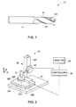
- a cutting tool 10 such as a ball end mill is illustrated.
- the illustrated cutting tool 10 comprises a shank 11 and a cylindrical cutting body 12.
- the cutting body 12 comprises a side portion 121 and a tip 122.
- the tip 122 comprises a rounded tip.
- the tip 122 may comprise other shapes, such as a flat tip when the cutting tool 10 comprises a flat end mill.
- the cutting body 12 comprises multiple cutting edges and multiple flutes 13 based on a desired profile of machined parts.
- a two-flute mill may be employed for cutting slots or grooves.
- a four-flute mill may be used for a surface milling operation.
- the cutting tool 10 has a number of parameters associated with the cutting body 12.
- Non-limiting examples of the parameters associated with the cutting body 12 comprise flute spacing, an axial primary relief angle, a radial primary relief angle, a radial rake angle, concentricity, a core diameter, an axial rake angle, a helix angle, an axial gash angle, a bottom gash angle, a gash walk angle, a gash end width, and an end gash radius.
- FIG. 2 is a schematic diagram of a measurement system 20 for extracting the parameters of the cutting tool 10 in accordance with one embodiment of the invention.
- the measurement system 20 comprises a base 21, a stage 22, a range sensor 23, and a controller 24.
- the stage 22 comprises a first stage 220 and a second stage 221.
- the first stage 220 is moveably disposed on the base 21 and comprises a positioning element 222 comprising a bottom element 223 and an upper element 224 stacked together.
- the bottom element 223 and the upper element 224 may move along an X-axis and a Y-axis relative to the base 21, respectively.
- the first stage 220 may further comprise a rotatable element 225 rotatably disposed on the upper element 224 for holding the cutting tool 10. Accordingly, the cutting tool 10 may move along the X-Y-axis and rotate about a Z-axis relative to the base 21 with the linear movement of the positioning element 222 and rotation of the rotatable element 225.
- the first stage 220 may move along the X-axis within a range of approximately zero millimeters to approximately fifty millimeters with a resolution of approximately 0.1 micrometers, and may move along the Y-axis within a range of approximately zero millimeters to approximately one hundred millimeters with a resolution of approximately 0.1 micrometers. In other embodiments, the first stage 220 may move along the X-axis and/or the Y-axis within other suitable ranges having any suitable resolution. Additionally, the rotatable element 225 may rotate approximately 360 degree with a resolution of approximately 0.0001 degrees. Alternatively, the rotatable element 225 may rotate within other suitable ranges with other suitable resolutions.
- the second stage 221 is fixedly disposed on the base 21 to moveably hold the range sensor 23 and adjacent to the first stage 220.
- the range sensor 23 may move on the second stage 221 along the Z-axis.
- the range sensor 23 may move along the Z-axis within a range of approximately zero millimeters to approximately 250 millimeters with a resolution of approximately 0.1 micrometers. In other embodiments, the range sensor 23 may move along the Z-axis within other suitable ranges and with other suitable resolutions.
- the range sensor 23 may also move on the second stage 221 along the X-axis and Y-axis within a range and with a resolution substantially similar to these of first stage 220.
- the second stage 221 may be moveably disposed on the base 21. Accordingly, in embodiments of the invention, the controller 24 may control the first stage 220 and the second stage 221 to cooperate to position the range sensor 23 at variable distances from the cutting tool 10 to measure the points on the cutting tool 10.
- the controller 24 comprises at least one of a computer, a database, and/or a processor to control the movement of the stage 22 and the range sensor 23, and to store and analyze the measured data points from the range sensor 23.
- a computer as that term is used herein, is intended to denote any machine capable of performing the calculations, or computations, necessary to perform the tasks of the invention.
- computer is intended to denote any machine that is capable of accepting a structured input and of processing the input in accordance with prescribed rules to produce an output.
- the phrase "configured to” as used herein means that the computer is equipped with a combination of hardware and software for performing the tasks of the invention, as will be understood by those skilled in the art. Additionally, the measurement system 10 may further comprise a monitor 25, such as a LCD to display data.
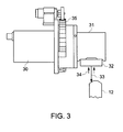
- FIG. 3 illustrates a schematic diagram of an example range sensor 23.
- the range sensor 23 comprises an optical sensor 30 and a periscope 31 coupled to the optical sensor 30.
- the optical sensor 30 comprises a conoscopic sensor, such as the Optimet Smart Probe described in U.S. Pat. No. 5,953,137 .
- the periscope 31 further comprises a lens 32.
- the optical sensor 30 may be another suitable ranging sensor.
- a light source (not shown) generates and directs a beam of light 33, such as a laser with a wavelength of 670nm on a point of the cutting tool 10 after the light 33 passes through the optical sensor 30 and the periscope 31 in turn. Then, a beam of reflected light 34 is generated because of diffusion of the light 33 on the point of the cutting tool 10. The diffused light 34 passes through the periscope 31 and is detected by the optical sensor 30. Subsequently, the controller 24 (shown in FIG. 2 ) retrieves a distance of the point on the cutting tool 10 from the optical sensor 30 and extracts the parameters of the point by analyzing information in the detected light 34, which is known to one skilled in the art. In one or more embodiments of the invention, with the rotation of the cutting tool 10, the optical sensor 30 may detect diffused light from different points on the cutting tool 10 so that the controller 24 extracts the parameters of the cutting tool 10.
- the controller 24 may determine the distance with an accuracy of approximately ⁇ 1.5 microns based on the information in the detected lights by the range sensor 23. In other embodiments, the controller 24 may determine the distance with other suitable accuracy.
- the incident light 33 has a frequency of up to approximately 3000 kilohertz. Alternatively, the incidence light 33 may have another suitable frequency.
- the range sensor 23 further comprises a rotation mechanism 35 coupled to the periscope 31.
- the controller 24 may control the rotation mechanism 35 to rotate the periscope 31 within a range of approximately zero degree to approximately ninety degree, or other suitable ranges.
- the rotation mechanism 35 rotates the periscope 31 to enable the lens 32 to align with the points on the side portion 121 or the tip 122 (shown in FIG. 1 ) of the cutting body 12.
- the optical sensor 30 may also be rotatable.
- the controller 24 when detecting gash parameters of the cutting tool 10, the controller 24 first controls the range sensor 23 and the first stage 220 holding the cutting tool 10 to move cooperatively so that the lens 32 aims at a desired gash section (not labeled) of the side portion 121 of the cutting body 12 with an appropriate distance therebetween. Then, the measurement system 20 rotates the cutting tool 10 while the light 33 scans the desired gash section with the rotation of the cutting tool 10. Meanwhile, the range sensor 23 detects the detected light 34 diffused from the desired gash section and outputs the detected information in the light 34 to the controller 24 for analyzing to retrieve a gash section scanning point cloud of the cutting tool 10. Similarly, more than one gash section scanning point cloud may be retrieved from more than one respective gash section. In certain applications, the gash section scanning point cloud may be retrieved from a whole or a partial gash section of the cutting tool 10.
- the retrieved gash section scanning point clouds may be as accurate as desired for gash parameter extraction.
- the retrieved gash section scanning point clouds may not be as accurate as desired due to the complex geometry of the gash sections of the cutting body 12 and limited working range of the range sensor 23.
- the measurement system 20 may perform one or more tip scans of the tip 122 to obtain information, such as shapes, of gash features of the cutting tool 10 for facilitating the subsequent scans of the gash sections so as to improve the quality of the gash section scanning point clouds.
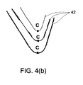
- FIGS. 4(a)-4(b) illustrate a schematic diagram of a tip (not labeled) and multiple tip scanning point clouds 41, and a schematic diagram of the tip scanning point clouds 41 of an example cutting tool.
- the tip of cutting tool and the tip scanning point clouds 41 are merely illustrative for facilitating illustration of the tip scanning point clouds therefrom. In certain applications, other types of cutting tools may be illustrated. In other applications, one tip scanning point cloud may be used for obtaining information of gash features.
- the tip scanning point clouds 41 are retrieved from the tip of the cutting tool. It can be seen that portions 42 of the tip scanning point clouds 41 corresponding to the respective gash features (not labeled) of the cutting tool are below other portions (not labeled) of the tip scanning point clouds 41. That is, the variance of the Z coordinate values of end points A and B on the portions 42 is large relative to other points on other portions.
- the Z coordinate values of the points on the tip scanning point clouds 41 can be calculated to determine the position of respective lowest points C thereon. Accordingly, after the tip scanning point clouds are retrieved, the controller 24 may detect the Z coordinate values of the points on the respective tip scanning point clouds to determine the position of the end points A and B, and the lowest points C. Subsequently, based on relationship of the end points A, B, and/or the lowest points C, the information, such as the shapes, of the respective gash features may be estimated. For example, the end points A and B of the gash features are determined. Based on the relationship of the end points A, the shapes of surfaces (not labeled) having the points A may be estimated as substantially linear planes.
- the information of the gash features of the cutting tool obtained from one or more tip scanning point clouds may facilitate the subsequent scans of the gash sections to retrieve the desired points and avoid missing some points so as to improve the quality of the gash section scanning point clouds.
- FIG. 5 illustrates a schematic diagram of multiple example gash section scanning point clouds 43 of a cutting tool (not shown).
- the example gash section scanning point clouds may be scanned based on the information obtained from the tip scan(s).
- the tip scans of the cutting tool may not be employed.
- the gash section scanning point clouds may be preprocessed in the controller 24 so as to improve the quality thereof.
- the gash section scanning point clouds may be transformed to the X-Y plane of a Cartesian coordinate system for the preprocessing.
- FIG. 6 illustrates a flowchart 50 for preprocessing one or more gash section scanning point clouds. It should be noted that the sequence of steps 51-54 is only illustrative and may be varied. In some examples, one or more of the steps in the flowchart 50 may be omitted.
- preprocessing one gash section scanning point cloud is taken as an example.
- the gash section scanning point cloud is decimated to remove redundant points therefrom using a Quadrant Tree (Quad tree) Structure, so that the points on the gash section scanning point cloud may be partitioned and distributed relatively uniformly after decimation.
- the distance (sample distance) between two adjacent points on the gash section scanning point cloud after decimation may be predetermined, so that the point cloud may be decimated based on the sample distance.
- the gash section scanning point cloud may have outliers, which may include a cluster of points whose size is smaller than a threshold cluster size and whose distance to neighboring points may exceed a threshold distance.
- the neighboring points of the outliers may be detected by using a K-dimensional tree structure to analyze the point cloud. Thus, in step 52 of the illustrated example, the outliers on the point cloud are determined and removed.
- step 53 of the illustrated example the gash section scanning point cloud is smoothed, for example by employing a Gaussian smoothing filter. In some examples, step 53 may be performed prior to or in the absence of steps 51 and/or 52.
- the point cloud may include some overlapping points having the same normal direction. Accordingly, the normal and curvature of every point on the gash section scanning point cloud may be estimated, for example using a Principle Component Analysis (PCA) method. If the distance between a point and one of its neighboring points is below a first threshold value, and an angle between the normals of the point and the neighboring points is below a second threshold value, the point and the neighboring point may be regarded as overlapping points.
- the first and second threshold values may be predetermined, and the neighboring points of one point may be determined, for example using a K-dimensional tree structure to analyze the point cloud. Accordingly, in step 54 of the illustrated example, overlapping points in normal directions are removed.
- the points on the gash section scanning point cloud may be sorted in step 55, and connected to form a polygon loop, so that a preprocessed gash section scanning point cloud may be obtained.
- the preprocessed gash section scanning point cloud may be re-sampled uniformly in step 56 so that a certain number of points are sampled to refine the preprocessed gash section scanning point cloud.
- more than one gash section scanning point cloud may also be preprocessed. In certain examples, the preprocessing of the gash section scanning point cloud(s) may not be employed.
- the controller 24 may index each point within the respective gash section scanning point clouds, so that each of these points has an index and may be positioned based on the corresponding index. In certain applications, the indexing may or may not be employed based on the gash section scanning point clouds without preprocessing.
- an initial starting point is indexed as Point[0].
- the position of the initial starting point may be adjusted to avoid being located at the relief regions or around the feature points.
- different cutting tools may have different working modes, such as right cutting and left cutting modes so that the indexing direction of a point cloud may be counterclockwise or clockwise.
- the indexing direction of the preprocessed gash section scanning point cloud point cloud is counterclockwise. Accordingly, in the illustrated example shown in FIG. 5 , if the indices of a point D and a point E are Point[d] and Point[e] respectively, the numeral "d" is larger than the numeral "e”. If the numeral "d” is smaller than the numeral "e”, the indexing of the points may be performed again according to the counterclockwise indexing direction. Alternatively, in other applications, the indexing direction may be clockwise.
- FIG. 7 illustrates a schematic diagram showing detection of the gash features of the example gash section scanning point clouds.
- the detection of the gash features of one of the gash section scanning point clouds 43 is taken as an example.
- the controller 24 may first analyze the gash section scanning point cloud 43 to detect the cutting edge feature points F, G, H, I so as to segment the gash section scanning point cloud 43 into four segments.
- other feature points including, but not limited to primary relief feature points, may be used for performing segmentation of the gash section scanning point cloud.
- the segmentation of the gash section scanning point cloud may be performed to make each segment include one gash feature.
- the cutting edge and/or primary relief feature points on the gash section scanning point cloud may be detected by using, for example convex hull analysis, or techniques described in a Non-provisional application Ser. No. 12/419,051 , filed April 6, 2009 (Docket number 194892-4), which has the same assignee as this application and the contents of which are hereby incorporated by reference.
- the detection of one gash feature of one segment of the gash section scanning point clouds 43 is selected as an example.
- a closest point 60 having the shortest distance from a central point O may be positioned on the segment, so that the position of the gash feature is roughly determined.
- the controller 24 analyzes the closest point 60 as well as points around the closest point 60 to detect two end points 61, 62 of the gash feature. As depicted in FIG. 7 , during detection of the end points 61, 62 of the segment, the closest point 60 is selected as a beginning point.
- a point set (not shown), such as a set of successive twenty points, is first selected behind (first subset) and in front of (second subset) the beginning point to generate a first (real) line 63 and a second (front) line 64 on the segment by connecting the beginning point and the distal points of two subsets respectively or by using, for example the Least Squares Method.
- the controller 24 calculates an outer angle from the first line 63 and the second line 64 to determine whether the outer angle therebetween is larger than a threshold value, such as 195 degrees.
- a threshold value such as 195 degrees.
- the term of "outer angle" may indicate that an angle faces outside of an area enclosed by one section scanning point cloud. In some applications, the outer angle is below the threshold value, and the controller 24 continues to analyze the points at each side of the beginning point 60 in turn until the desired points, which may be the end points 61, 62, are detected. That is, an outer angle of two lines (not shown) formed in front of and behind each of the end points 61, 62 is larger than the threshold value. In certain applications, instead of forming two lines at two sides of each closest point, two lines may be first formed at two sides of points located in front of and behind each closest point for detecting the end points of each gash feature.
- the gash feature may be determined.
- the gash features of one or more of the gash section scanning point clouds 43 may be detected.
- the point set may include less than or more than twenty points.
- the threshold value may be experimentally determined.
- the controller 24 analyzes the gash feature point clouds (not labeled) of the same segment(s) of the gash section scanning point clouds 43 to detect one or more desired projection lines.
- the corresponding gash feature point clouds may be projected into one gash feature point cloud for facilitating extraction of the gash parameters.
- projection lines, as indicated by points 65-68, of the gash feature point clouds in the respective segments are detected, for example, by rotating and projecting the corresponding gash feature points clouds, so that the corresponding gash feature points clouds in each segment are projected into one gash feature point cloud 44, 45, 46, or 47.
- each of the projection lines may be rotated to be parallel to an axial line, as indicated by the central point O, of the cutting tool, so as to facilitate subsequent calculation of the gash parameters.
- the controller 24 may first determine the types of the gash features based on the respective projected gash feature point clouds.
- two types of gash features may be determined.
- the first type of gash feature includes two side planes and one cylindrical surface connecting the two side planes.
- the second type of gash feature for these examples includes two side planes, a bottom plane located between the two side planes, and two cylindrical surfaces connecting the two side planes and the bottom plane, respectively.
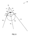
- FIGS. 9-10 are schematic diagrams illustrating identification of the types of the gash features.
- the identification of the gash feature point clouds 44, 47 are taken as examples respectively. It should be noted that the same numerals are used in FIGS. 9 and 10 for ease of illustration.
- a first sideline 71 and a second sideline 72 are formed on the two sides 73, 74 (which indicate the side planes of the gash feature) of the gash feature point cloud 44 or 47 respectively, and are intersected with each other to form a first intersection point 75.
- an internal bisector 76 is calculated between the two sides 73, 74, and a point 77 having the first shortest distance from the internal bisector 76 is positioned on the gash feature point cloud 44 or 47.
- an inscribed circle 78 tangent to the two sides 73, 74 and passing through the point 77 is detected and has a second intersection point 79 with the internal bisector 76.
- a point 81 (shown in FIG. 10 ) having a second shortest distance with the second intersection point 79 may be detected on the gash feature point cloud 44 or 47.
- the controller 24 calculates distances between the first shortest point 77 and the second intersection point 79, and between the first shortest point 77 and the second shortest point.
- the controller 24 may first analyze whether at least one of the distances between the first shortest point 77 and the second intersection point 79, and between the first shortest point 77 and the second shortest point 81 is below or equal to a corresponding first threshold value predetermined in the controller 24. If one of the distances is below or equal to the corresponding first threshold value, the gash feature may be identified as being the first type, as depicted in FIG. 9 . If both of the two distances are larger than respective first respective threshold values and at least one of the two distances is larger than a corresponding second threshold value predetermined in the controller 24, the gash feature may be identified as being the second type, as depicted in FIG. 10 .
- a first connecting line 82 connecting the tangent points T1, T2 is determined. Then, a first point 83 (shown in FIG. 10 ) having the first furthest distance from the first connecting line 82 is positioned, so that a bottom part (not labeled) of the gash feature point cloud 44 or 47 is segmented into two segments. In the illustrated embodiment, the bottom part is referred to as an enclosure portion defined by the first connecting line 82 and the gash feature point cloud 44 or 47.
- the first furthest point 83 and the points T1, T2 are connected respectively to form a second connecting line 84 and a third connecting line 85. Subsequently, a second point 86 and a third point 87 having the second and third furthest distances from the respective first line 84 and second line 85 are detected.
- the controller 24 determines whether the second and/or third furthest distances are below or equal to respective predetermined values.
- the tangent points T1, T2 may be or may not be on the gash feature point cloud 44 or 47.
- the second point 86 and the point T1, and/or a third point 87 and the point T2 may be connected to form a fourth connecting line and/or a fifth connecting line (not shown). Then, a fourth point and/or a fifth point (not shown) having a fourth and/or fifth furthest distances from the respective fourth and/or fifth connecting lines are detected. The controller 24 determines whether the fourth and/or fifth furthest distances are smaller than or equal to the respective predetermined values.
- a similar process may be performed iteratively until such point(s) are detected, whose furthest distance(s) from respective connecting line(s) are below or equal to the respective predetermined value(s).
- the threshold and predetermined values as described above may be experimentally determined.
- the controller 24 may fit points between the second and third points 86, 87 to form a first fitted line (not shown) and calculate the standard deviation of the first fitted line. In certain applications, if the standard deviation of the first fitted line is acceptable compared to a first experimental value, in certain examples, the controller 24 may further calculate a length of the first fitted line. When the length of the first fitted line is larger than or equal to a certain portion of a length of the bottom part, the gash feature may be identified as being the second type, as depicted in FIG. 10 .
- the controller 24 may further fit the points between the second and the third points 86, 87 to form a fitted arc. If the standard deviation of the fitted arc is acceptable, the gash feature may be identified as being the first type, as depicted in FIG. 9 . If the standard deviation of the fitted arc is unacceptable compared to a second experimental value, the gash feature may be identified as being the second type, as depicted in FIG. 10 .
- the controller 24 may further fit the points between the second point 86 and the third point 87 to form the fitted arc (not shown). If the standard deviation of the fitted arc is acceptable, the gash feature may be identified as being the first type, as depicted in FIG. 9 . If the standard deviation of the fitted arc is unacceptable compared to the second experimental value, the gash feature may be identified as being the second type, as depicted in FIG. 10 .
- the controller 24 may segment one or more of the gash feature point clouds 44-47.
- the second type of the gash feature point cloud 47 is taken for an example.
- the closest point 60 (shown in FIG. 7 ) is determined, so that the gash feature point cloud is segmented into two segments using the closest point 60. Since the two end points 61, 62 are also detected, a first connection line 90 and a second connection line 91 are formed by connecting the two end points 61, 62 and the closest point 60.
- a first distance point 92 and a second distance point 93 having the respective furthest distances from the connection lines 90 and 91 are detected.
- the controller 24 determines whether the respective furthest distances are below or equal to respective predetermined distance values.
- one or two of the furthest distances may be not below or equal to respective predetermined values.
- the distance from the first distance point 92 to the connection line 90 is not below or equal to the corresponding predetermined value.
- the first distance point 92 and the end point 61 may be connected to form a third connection line (not shown).
- a third distance point (not shown) having a furthest distance from the third connection line is detected.
- the controller 24 determines whether the distance between the third distance point and the third connection line is below or equal to the predetermined value. In this manner, the process may be performed iteratively until a desired point is detected, whose distance from a corresponding connecting line is below or equal to the predetermined value.
- a desired distance point between the point 60 and the point 61 may also be detected.
- the gash feature point cloud 47 is segmented into three segments using the first and second distance points 92, 93.
- the gash feature point cloud 44 (shown in FIG. 9 ) may be also segmented into three segments.
- the gash parameters may be extracted accordingly based on the segmentation. For example, an angle between the two sides 73, 74 (shown in FIG. 9 ) may be calculated to retrieve the bottom gash angle of the corresponding gash feature.
- the first and second distance points 92, 93 may be connected to form a first connected line (not labeled). Similar to the process for identifying the types of the gash features show in FIGS. 9-10 , a point (not shown) having the furthest distance from the first connected line is positioned on the point cloud between the two points 92 and 93, so that the gash feature point cloud between the distance points 92, 93 is segmented into two segments. Next, the point and the points 92, 93 are connected to form two connected lines, respectively. Subsequently, the controller 24 continues to detect points having the furthest distances from the respective connected lines on the gash feature point cloud 47, and determines whether the respective furthest distances are below or equal to respective predetermined threshold values.
- the controller 24 uses a process similar to the process for determining the types of the gash features to determine desired points (partition points), such as points 94, 95, so as to segment the gash feature point cloud 47 therebetween into three sub-segments. Accordingly, the gash feature point cloud 47 is segmented into five segments in terms of the first distance point 92 and the second distance point 93, and the two determined points 94, 95. In some applications, the points between the two desired points may be used to form a line (not shown).
- the desired gash parameters may be extracted.
- the gash width is extracted by calculating the distance between two intersection points of two sidelines 71,72 (shown in FIGS. 9-10 ) and the line fitted from the points between the two desired points 94, 95.
- a 3D (three dimensional) scanning point cloud (not shown) of a cutting tool may be retrieved, which comprises tip scanning point clouds and gash section scanning point clouds.
- multiple points may be selected by an user on multiple planes of one or more gash features, which may be determined from the 3D scanning point cloud. Then, the points on the respective planes are used to form lines and/or planes, based upon which the gash parameters may be extracted.
Landscapes
- Physics & Mathematics (AREA)
- Engineering & Computer Science (AREA)
- Mechanical Engineering (AREA)
- General Physics & Mathematics (AREA)
- Optics & Photonics (AREA)
- Length Measuring Devices By Optical Means (AREA)
Applications Claiming Priority (1)
| Application Number | Priority Date | Filing Date | Title |
|---|---|---|---|
| US12/431,999 US8112172B2 (en) | 2009-04-29 | 2009-04-29 | Method and system for gash parameter extraction of a cutting tool |
Publications (2)
| Publication Number | Publication Date |
|---|---|
| EP2246149A2 true EP2246149A2 (de) | 2010-11-03 |
| EP2246149A3 EP2246149A3 (de) | 2017-06-14 |
Family
ID=42340498
Family Applications (1)
| Application Number | Title | Priority Date | Filing Date |
|---|---|---|---|
| EP10161434.5A Withdrawn EP2246149A3 (de) | 2009-04-29 | 2010-04-29 | Verfahren und System zur Einschnittparameterextraktion eines Schneidwerkzeugs |
Country Status (4)
| Country | Link |
|---|---|
| US (1) | US8112172B2 (de) |
| EP (1) | EP2246149A3 (de) |
| JP (1) | JP5629117B2 (de) |
| CA (1) | CA2701287C (de) |
Cited By (4)
| Publication number | Priority date | Publication date | Assignee | Title |
|---|---|---|---|---|
| CN102682136A (zh) * | 2011-03-10 | 2012-09-19 | 鸿富锦精密工业(深圳)有限公司 | 产品段差及间隙分析系统及方法 |
| WO2013043329A1 (en) * | 2011-09-23 | 2013-03-28 | General Electric Company | Method for obtaining edge prep profiles of cutting tools |
| EP2901221B1 (de) | 2012-09-26 | 2017-03-22 | Blum-Novotest GmbH | Verfahren und vorrichtung zum vermessen eines in einer werkstückbearbeitungsmaschine aufgenommenen werkzeugs |
| CN111702490A (zh) * | 2020-06-17 | 2020-09-25 | 陕西飞机工业(集团)有限公司 | 一种装配对接部位端面自动精加工工艺方法 |
Families Citing this family (11)
| Publication number | Priority date | Publication date | Assignee | Title |
|---|---|---|---|---|
| CN103186704A (zh) * | 2011-12-29 | 2013-07-03 | 鸿富锦精密工业(深圳)有限公司 | 寻线过滤系统及方法 |
| CN103322931A (zh) * | 2012-03-23 | 2013-09-25 | 鸿富锦精密工业(深圳)有限公司 | 点云间隙与断差量测系统及方法 |
| CN103363920A (zh) * | 2012-04-09 | 2013-10-23 | 鸿富锦精密工业(深圳)有限公司 | 刀具检测系统及方法 |
| US10304256B2 (en) * | 2016-12-13 | 2019-05-28 | Indoor Reality Inc. | Point cloud cleaning method |
| EP3450909A1 (de) * | 2017-09-05 | 2019-03-06 | Renishaw PLC | Vorrichtung und verfahren zur optisch kontaktlosen werkzeugeinrichtung |
| CN111971150A (zh) | 2018-04-20 | 2020-11-20 | 柯惠Lp公司 | 手术机器人手推车放置的系统和方法 |
| CN110738180B (zh) * | 2019-10-21 | 2022-05-17 | 易思维(杭州)科技有限公司 | 对检测过程中信号准确度及系统精度进行评估的方法 |
| CN111292275B (zh) * | 2019-12-26 | 2023-10-24 | 深圳一清创新科技有限公司 | 基于复杂地面的点云数据滤除方法、装置、计算机设备 |
| CN114370816A (zh) * | 2022-01-11 | 2022-04-19 | 苏州天准科技股份有限公司 | 一种组装间隙测量方法、存储介质、终端和系统 |
| CN116442005A (zh) * | 2023-04-04 | 2023-07-18 | 西安交通大学 | 一种基于线激光的pcd轮廓铣刀定位方法 |
| CN116592787A (zh) * | 2023-04-04 | 2023-08-15 | 奥比中光科技集团股份有限公司 | 一种基于单站点的转轴标定方法、装置、系统及存储介质 |
Citations (1)
| Publication number | Priority date | Publication date | Assignee | Title |
|---|---|---|---|---|
| US5953137A (en) | 1996-10-09 | 1999-09-14 | Optimet, Optical Metrology Ltd. | Linear conoscopic holography |
Family Cites Families (32)
| Publication number | Priority date | Publication date | Assignee | Title |
|---|---|---|---|---|
| DE2015694B2 (de) | 1970-04-02 | 1971-11-11 | Exatest Meßtechnik GmbH, 5090 Le verkusen | Verfahren zur beruehrungslosen messung der breite oder lage eines gegenstandes mittels eines sichtstrahls |
| US3692414A (en) | 1971-02-24 | 1972-09-19 | Harry L Hosterman | Non-contacting measuring probe |
| US4403860A (en) | 1980-03-27 | 1983-09-13 | Diffracto Ltd. | Apparatus for determining dimensions |
| US4583854A (en) | 1982-07-15 | 1986-04-22 | General Electric Company | High resolution electronic automatic imaging and inspecting system |
| US4745290A (en) | 1987-03-19 | 1988-05-17 | David Frankel | Method and apparatus for use in making custom shoes |
| US4736247A (en) | 1987-05-04 | 1988-04-05 | The United States Of America As Represented By The Administrator Of The National Aeronautics And Space Administration | Range and range rate system |
| US4966460A (en) | 1987-10-28 | 1990-10-30 | The Ingersoll Milling Machine Company | Laser gauging of rotary cutting tools |
| US5369286A (en) | 1989-05-26 | 1994-11-29 | Ann F. Koo | Method and apparatus for measuring stress in a film applied to surface of a workpiece |
| JP2920799B2 (ja) | 1992-01-31 | 1999-07-19 | ユニオンツール株式会社 | 切削工具の検査装置 |
| US5570186A (en) | 1992-04-28 | 1996-10-29 | Mtu Motoren- Und Turbinen-Union Munich Gmbh | Method for inspecting the curvature of a profile, such an edge of a turbine blade |
| JPH05329751A (ja) | 1992-05-28 | 1993-12-14 | Union Tool Kk | 切削工具の検査装置 |
| US5477371A (en) | 1993-12-13 | 1995-12-19 | Shafir Production Systems Ltd. | Three-dimensional, non-contact scanning apparatus and method |
| US5568260A (en) | 1995-03-31 | 1996-10-22 | General Electric Company | Precision non-contact measurement system for curved workpieces |
| US5846081A (en) | 1995-08-23 | 1998-12-08 | Bushway; Geoffrey C. | Computerized instrument platform positioning system |
| US6788807B1 (en) | 1998-02-13 | 2004-09-07 | Minolta Co., Ltd. | Three dimensional information measurement method and apparatus |
| US6185030B1 (en) | 1998-03-20 | 2001-02-06 | James W. Overbeck | Wide field of view and high speed scanning microscopy |
| JP2000074644A (ja) * | 1998-08-31 | 2000-03-14 | Nachi Fujikoshi Corp | 棒状切削工具の測定装置並びに該測定装置を使用したドリルの測定方法 |
| JP2000293551A (ja) | 1999-02-03 | 2000-10-20 | Kobe Steel Ltd | 2次元配置決定方法及びその装置 |
| JP2001075624A (ja) | 1999-07-01 | 2001-03-23 | Mori Seiki Co Ltd | Nc工作機械のツールパスデータ生成装置及びこれを備えた数値制御装置 |
| DE10000491B4 (de) * | 2000-01-08 | 2004-09-23 | Kelch Gmbh + Co Werkzeugmaschinenfabrik | Verfahren und Messeinrichtung zum Vermessen eines Rotationswerkzeuges |
| DE10157964B4 (de) * | 2001-11-26 | 2011-06-22 | Siemens AG, 80333 | Verfahren zur Optimierung einer Oberflächengüte eines zu fertigenden Werkstücks anhand von CNC-Programmdaten |
| DE10211070A1 (de) | 2002-03-13 | 2003-09-25 | Gurny Broesch Andrea | Vorrichtung zum Vermessen eines Messobjekts |
| US20040263863A1 (en) | 2003-01-27 | 2004-12-30 | Rogers William E | System and method for design and manufacture of custom face masks |
| US7027145B2 (en) | 2003-06-24 | 2006-04-11 | The Regents Of The University Of Michigan | Reconfigurable surface finish inspection apparatus for cylinder bores and other surfaces |
| DE102004014153A1 (de) | 2004-03-23 | 2005-10-13 | IBTL - Ing. Büro Lang & Armlich GmbH | Koordinatenmessgerät mit Wechseloptik |
| US7577491B2 (en) | 2005-11-30 | 2009-08-18 | General Electric Company | System and method for extracting parameters of a cutting tool |
| US20070196190A1 (en) | 2005-12-15 | 2007-08-23 | Ingersoll Machine Tools, Inc. | Determining cutting tool dimensions and run-out using acoustic emissions |
| US7768655B2 (en) | 2006-12-20 | 2010-08-03 | General Electric Company | Methods and system for measuring an object |
| US7876454B2 (en) | 2006-12-20 | 2011-01-25 | General Electric Company | Method and system for measurement of a cutting tool |
| JP2008196989A (ja) | 2007-02-14 | 2008-08-28 | General Electric Co <Ge> | 切削工具のパラメータを抽出するためのシステム及び方法 |
| CN101424520B (zh) * | 2007-10-31 | 2011-03-23 | 鸿富锦精密工业(深圳)有限公司 | 物件曲面的局部轮廓检测方法 |
| US7924439B2 (en) * | 2008-09-29 | 2011-04-12 | General Electric Company | Method and system for parameter extraction of a cutting tool |
-
2009
- 2009-04-29 US US12/431,999 patent/US8112172B2/en active Active
-
2010
- 2010-04-20 JP JP2010096578A patent/JP5629117B2/ja not_active Expired - Fee Related
- 2010-04-22 CA CA2701287A patent/CA2701287C/en not_active Expired - Fee Related
- 2010-04-29 EP EP10161434.5A patent/EP2246149A3/de not_active Withdrawn
Patent Citations (1)
| Publication number | Priority date | Publication date | Assignee | Title |
|---|---|---|---|---|
| US5953137A (en) | 1996-10-09 | 1999-09-14 | Optimet, Optical Metrology Ltd. | Linear conoscopic holography |
Cited By (5)
| Publication number | Priority date | Publication date | Assignee | Title |
|---|---|---|---|---|
| CN102682136A (zh) * | 2011-03-10 | 2012-09-19 | 鸿富锦精密工业(深圳)有限公司 | 产品段差及间隙分析系统及方法 |
| CN102682136B (zh) * | 2011-03-10 | 2015-11-25 | 鸿富锦精密工业(深圳)有限公司 | 产品段差及间隙分析系统及方法 |
| WO2013043329A1 (en) * | 2011-09-23 | 2013-03-28 | General Electric Company | Method for obtaining edge prep profiles of cutting tools |
| EP2901221B1 (de) | 2012-09-26 | 2017-03-22 | Blum-Novotest GmbH | Verfahren und vorrichtung zum vermessen eines in einer werkstückbearbeitungsmaschine aufgenommenen werkzeugs |
| CN111702490A (zh) * | 2020-06-17 | 2020-09-25 | 陕西飞机工业(集团)有限公司 | 一种装配对接部位端面自动精加工工艺方法 |
Also Published As
| Publication number | Publication date |
|---|---|
| JP5629117B2 (ja) | 2014-11-19 |
| EP2246149A3 (de) | 2017-06-14 |
| JP2010261941A (ja) | 2010-11-18 |
| US20100280649A1 (en) | 2010-11-04 |
| US8112172B2 (en) | 2012-02-07 |
| CA2701287A1 (en) | 2010-10-29 |
| CA2701287C (en) | 2012-11-13 |
Similar Documents
| Publication | Publication Date | Title |
|---|---|---|
| CA2701287C (en) | Method and system for gash parameter extraction of a cutting tool | |
| US7924439B2 (en) | Method and system for parameter extraction of a cutting tool | |
| US7577491B2 (en) | System and method for extracting parameters of a cutting tool | |
| US7876454B2 (en) | Method and system for measurement of a cutting tool | |
| EP3168808B1 (de) | System zur automatischen messung von geformten kühlungsbohrungen | |
| CN107532886B (zh) | 工具形状测定装置 | |
| US7768655B2 (en) | Methods and system for measuring an object | |
| US20140238119A1 (en) | Method for obtaining edge prep profiles of cutting tools | |
| González et al. | Adaptive edge finishing process on distorted features through robot-assisted computer vision | |
| JP2008196989A (ja) | 切削工具のパラメータを抽出するためのシステム及び方法 | |
| CN101246506A (zh) | 提取刀具参数的系统和方法 | |
| US7912572B2 (en) | Calibration assembly for an inspection system | |
| Ghorbani et al. | Accurate registration of point clouds of damaged aeroengine blades | |
| Póka et al. | A robust digital image processing method for measuring the planar burr length at milling | |
| EP1351033B1 (de) | Dreidimensionale Randlokalisierung unter Anwendung von seitlicher Beleuchtung | |
| CN113008143A (zh) | 用于确定工件的两点大小的方法和设备 | |
| CN116243654A (zh) | 整体叶盘叶片的宽行加工方法及相关装置 | |
| Motavalli et al. | Modular software development for digitizing systems data analysis in reverse engineering applications: case of concentric rotational parts | |
| Pei et al. | Research on Profile Geometric Feature Parameters Extraction of Complicated Thin-Walled Ring Parts with Irregular Section | |
| CN120313518A (zh) | 基于线激光扫描的螺尖丝锥几何参数测量方法 | |
| JP2000055628A (ja) | 工具寸法測定方法 | |
| Zhang et al. | Segmentation and Geometric Feature Extraction of Film Cooling Hole in Turbine Blade | |
| Zhang et al. | Robust film-cooling hole segmentation and geometric characterization in turbine blade | |
| Du et al. | Method for Extracting Laser Stripe Centerlines on Complex Deep Hole Surfaces Based on Minimum Spanning Tree and Depth-First Search | |
| Chen et al. | Data processing and parameter extraction for cutting tool inspection |
Legal Events
| Date | Code | Title | Description |
|---|---|---|---|
| PUAI | Public reference made under article 153(3) epc to a published international application that has entered the european phase |
Free format text: ORIGINAL CODE: 0009012 |
|
| AK | Designated contracting states |
Kind code of ref document: A2 Designated state(s): AT BE BG CH CY CZ DE DK EE ES FI FR GB GR HR HU IE IS IT LI LT LU LV MC MK MT NL NO PL PT RO SE SI SK SM TR |
|
| AX | Request for extension of the european patent |
Extension state: AL BA ME RS |
|
| PUAL | Search report despatched |
Free format text: ORIGINAL CODE: 0009013 |
|
| AK | Designated contracting states |
Kind code of ref document: A3 Designated state(s): AT BE BG CH CY CZ DE DK EE ES FI FR GB GR HR HU IE IS IT LI LT LU LV MC MK MT NL NO PL PT RO SE SI SK SM TR |
|
| AX | Request for extension of the european patent |
Extension state: AL BA ME RS |
|
| RIC1 | Information provided on ipc code assigned before grant |
Ipc: B23Q 17/24 20060101ALI20170510BHEP Ipc: G01B 11/24 20060101AFI20170510BHEP |
|
| STAA | Information on the status of an ep patent application or granted ep patent |
Free format text: STATUS: THE APPLICATION IS DEEMED TO BE WITHDRAWN |
|
| 18D | Application deemed to be withdrawn |
Effective date: 20171215 |