EP2246004B1 - Gefässabdichtung und -trenner zur Verwendung in kleinen Trokaren und Kanülen - Google Patents
Gefässabdichtung und -trenner zur Verwendung in kleinen Trokaren und Kanülen Download PDFInfo
- Publication number
- EP2246004B1 EP2246004B1 EP10172005.0A EP10172005A EP2246004B1 EP 2246004 B1 EP2246004 B1 EP 2246004B1 EP 10172005 A EP10172005 A EP 10172005A EP 2246004 B1 EP2246004 B1 EP 2246004B1
- Authority
- EP
- European Patent Office
- Prior art keywords
- jaw member
- tissue
- assembly
- handle
- movable
- Prior art date
- Legal status (The legal status is an assumption and is not a legal conclusion. Google has not performed a legal analysis and makes no representation as to the accuracy of the status listed.)
- Expired - Lifetime
Links
- 241001631457 Cannula Species 0.000 title description 3
- 238000007789 sealing Methods 0.000 claims description 49
- 230000000694 effects Effects 0.000 claims description 10
- 239000012636 effector Substances 0.000 description 39
- 230000004913 activation Effects 0.000 description 22
- 238000000034 method Methods 0.000 description 18
- 230000037361 pathway Effects 0.000 description 15
- 230000008901 benefit Effects 0.000 description 14
- 238000005520 cutting process Methods 0.000 description 14
- 230000007246 mechanism Effects 0.000 description 13
- 239000012212 insulator Substances 0.000 description 11
- 239000000463 material Substances 0.000 description 10
- 230000008569 process Effects 0.000 description 8
- 230000001276 controlling effect Effects 0.000 description 7
- 238000004519 manufacturing process Methods 0.000 description 7
- PXHVJJICTQNCMI-UHFFFAOYSA-N Nickel Chemical compound [Ni] PXHVJJICTQNCMI-UHFFFAOYSA-N 0.000 description 6
- 230000006835 compression Effects 0.000 description 5
- 238000007906 compression Methods 0.000 description 5
- 229910052751 metal Inorganic materials 0.000 description 5
- 239000002184 metal Substances 0.000 description 5
- 230000000712 assembly Effects 0.000 description 4
- 238000000429 assembly Methods 0.000 description 4
- 210000004204 blood vessel Anatomy 0.000 description 4
- 238000010438 heat treatment Methods 0.000 description 4
- 238000001356 surgical procedure Methods 0.000 description 4
- 238000013461 design Methods 0.000 description 3
- 238000010304 firing Methods 0.000 description 3
- 229910052759 nickel Inorganic materials 0.000 description 3
- 238000002355 open surgical procedure Methods 0.000 description 3
- 230000002028 premature Effects 0.000 description 3
- 230000009467 reduction Effects 0.000 description 3
- 238000000926 separation method Methods 0.000 description 3
- 230000002792 vascular Effects 0.000 description 3
- 230000003213 activating effect Effects 0.000 description 2
- 238000005452 bending Methods 0.000 description 2
- 230000000740 bleeding effect Effects 0.000 description 2
- 238000005345 coagulation Methods 0.000 description 2
- 230000015271 coagulation Effects 0.000 description 2
- 238000000576 coating method Methods 0.000 description 2
- 238000000151 deposition Methods 0.000 description 2
- 230000000994 depressogenic effect Effects 0.000 description 2
- 238000012976 endoscopic surgical procedure Methods 0.000 description 2
- 238000005516 engineering process Methods 0.000 description 2
- 230000008713 feedback mechanism Effects 0.000 description 2
- 229910001055 inconels 600 Inorganic materials 0.000 description 2
- 238000001746 injection moulding Methods 0.000 description 2
- 238000012986 modification Methods 0.000 description 2
- 230000004048 modification Effects 0.000 description 2
- 230000002093 peripheral effect Effects 0.000 description 2
- 230000001105 regulatory effect Effects 0.000 description 2
- 239000000758 substrate Substances 0.000 description 2
- VYZAMTAEIAYCRO-UHFFFAOYSA-N Chromium Chemical compound [Cr] VYZAMTAEIAYCRO-UHFFFAOYSA-N 0.000 description 1
- 102000008186 Collagen Human genes 0.000 description 1
- 108010035532 Collagen Proteins 0.000 description 1
- 241000237503 Pectinidae Species 0.000 description 1
- 229910010037 TiAlN Inorganic materials 0.000 description 1
- 230000009471 action Effects 0.000 description 1
- 230000003044 adaptive effect Effects 0.000 description 1
- 239000000853 adhesive Substances 0.000 description 1
- 230000001070 adhesive effect Effects 0.000 description 1
- 229910045601 alloy Inorganic materials 0.000 description 1
- 239000000956 alloy Substances 0.000 description 1
- 210000001367 artery Anatomy 0.000 description 1
- SJKRCWUQJZIWQB-UHFFFAOYSA-N azane;chromium Chemical compound N.[Cr] SJKRCWUQJZIWQB-UHFFFAOYSA-N 0.000 description 1
- 238000009395 breeding Methods 0.000 description 1
- 230000001488 breeding effect Effects 0.000 description 1
- 229910010293 ceramic material Inorganic materials 0.000 description 1
- 239000011651 chromium Substances 0.000 description 1
- 230000007012 clinical effect Effects 0.000 description 1
- 230000001112 coagulating effect Effects 0.000 description 1
- 239000011248 coating agent Substances 0.000 description 1
- 229920001436 collagen Polymers 0.000 description 1
- 238000010276 construction Methods 0.000 description 1
- 230000006378 damage Effects 0.000 description 1
- 230000008021 deposition Effects 0.000 description 1
- 230000001627 detrimental effect Effects 0.000 description 1
- 238000002674 endoscopic surgery Methods 0.000 description 1
- 230000023597 hemostasis Effects 0.000 description 1
- 238000002347 injection Methods 0.000 description 1
- 239000007924 injection Substances 0.000 description 1
- 238000003780 insertion Methods 0.000 description 1
- 230000037431 insertion Effects 0.000 description 1
- CLDVQCMGOSGNIW-UHFFFAOYSA-N nickel tin Chemical compound [Ni].[Sn] CLDVQCMGOSGNIW-UHFFFAOYSA-N 0.000 description 1
- 150000004767 nitrides Chemical class 0.000 description 1
- 210000000056 organ Anatomy 0.000 description 1
- 230000000750 progressive effect Effects 0.000 description 1
- 235000020637 scallop Nutrition 0.000 description 1
- 230000037390 scarring Effects 0.000 description 1
- 238000010008 shearing Methods 0.000 description 1
- 238000005507 spraying Methods 0.000 description 1
- 239000010935 stainless steel Substances 0.000 description 1
- 229910001220 stainless steel Inorganic materials 0.000 description 1
- -1 stamping Substances 0.000 description 1
- 238000007751 thermal spraying Methods 0.000 description 1
- 230000000451 tissue damage Effects 0.000 description 1
- 231100000827 tissue damage Toxicity 0.000 description 1
- 238000012546 transfer Methods 0.000 description 1
- 238000013519 translation Methods 0.000 description 1
- 230000000007 visual effect Effects 0.000 description 1
- 238000003466 welding Methods 0.000 description 1
Images


Classifications
-
- A—HUMAN NECESSITIES
- A61—MEDICAL OR VETERINARY SCIENCE; HYGIENE
- A61B—DIAGNOSIS; SURGERY; IDENTIFICATION
- A61B18/00—Surgical instruments, devices or methods for transferring non-mechanical forms of energy to or from the body
- A61B18/04—Surgical instruments, devices or methods for transferring non-mechanical forms of energy to or from the body by heating
- A61B18/12—Surgical instruments, devices or methods for transferring non-mechanical forms of energy to or from the body by heating by passing a current through the tissue to be heated, e.g. high-frequency current
- A61B18/14—Probes or electrodes therefor
- A61B18/1442—Probes having pivoting end effectors, e.g. forceps
- A61B18/1445—Probes having pivoting end effectors, e.g. forceps at the distal end of a shaft, e.g. forceps or scissors at the end of a rigid rod
-
- A—HUMAN NECESSITIES
- A61—MEDICAL OR VETERINARY SCIENCE; HYGIENE
- A61B—DIAGNOSIS; SURGERY; IDENTIFICATION
- A61B17/00—Surgical instruments, devices or methods
- A61B17/32—Surgical cutting instruments
-
- A—HUMAN NECESSITIES
- A61—MEDICAL OR VETERINARY SCIENCE; HYGIENE
- A61B—DIAGNOSIS; SURGERY; IDENTIFICATION
- A61B17/00—Surgical instruments, devices or methods
- A61B17/28—Surgical forceps
- A61B17/29—Forceps for use in minimally invasive surgery
- A61B17/2909—Handles
- A61B2017/2912—Handles transmission of forces to actuating rod or piston
- A61B2017/2919—Handles transmission of forces to actuating rod or piston details of linkages or pivot points
-
- A—HUMAN NECESSITIES
- A61—MEDICAL OR VETERINARY SCIENCE; HYGIENE
- A61B—DIAGNOSIS; SURGERY; IDENTIFICATION
- A61B17/00—Surgical instruments, devices or methods
- A61B17/28—Surgical forceps
- A61B17/29—Forceps for use in minimally invasive surgery
- A61B17/2909—Handles
- A61B2017/2925—Pistol grips
-
- A—HUMAN NECESSITIES
- A61—MEDICAL OR VETERINARY SCIENCE; HYGIENE
- A61B—DIAGNOSIS; SURGERY; IDENTIFICATION
- A61B17/00—Surgical instruments, devices or methods
- A61B17/28—Surgical forceps
- A61B17/29—Forceps for use in minimally invasive surgery
- A61B2017/2926—Details of heads or jaws
- A61B2017/2932—Transmission of forces to jaw members
- A61B2017/2933—Transmission of forces to jaw members camming or guiding means
-
- A—HUMAN NECESSITIES
- A61—MEDICAL OR VETERINARY SCIENCE; HYGIENE
- A61B—DIAGNOSIS; SURGERY; IDENTIFICATION
- A61B18/00—Surgical instruments, devices or methods for transferring non-mechanical forms of energy to or from the body
- A61B2018/00315—Surgical instruments, devices or methods for transferring non-mechanical forms of energy to or from the body for treatment of particular body parts
- A61B2018/00345—Vascular system
- A61B2018/00404—Blood vessels other than those in or around the heart
-
- A—HUMAN NECESSITIES
- A61—MEDICAL OR VETERINARY SCIENCE; HYGIENE
- A61B—DIAGNOSIS; SURGERY; IDENTIFICATION
- A61B18/00—Surgical instruments, devices or methods for transferring non-mechanical forms of energy to or from the body
- A61B2018/00571—Surgical instruments, devices or methods for transferring non-mechanical forms of energy to or from the body for achieving a particular surgical effect
- A61B2018/00601—Cutting
-
- A—HUMAN NECESSITIES
- A61—MEDICAL OR VETERINARY SCIENCE; HYGIENE
- A61B—DIAGNOSIS; SURGERY; IDENTIFICATION
- A61B18/00—Surgical instruments, devices or methods for transferring non-mechanical forms of energy to or from the body
- A61B2018/00571—Surgical instruments, devices or methods for transferring non-mechanical forms of energy to or from the body for achieving a particular surgical effect
- A61B2018/0063—Sealing
-
- A—HUMAN NECESSITIES
- A61—MEDICAL OR VETERINARY SCIENCE; HYGIENE
- A61B—DIAGNOSIS; SURGERY; IDENTIFICATION
- A61B18/00—Surgical instruments, devices or methods for transferring non-mechanical forms of energy to or from the body
- A61B18/04—Surgical instruments, devices or methods for transferring non-mechanical forms of energy to or from the body by heating
- A61B18/12—Surgical instruments, devices or methods for transferring non-mechanical forms of energy to or from the body by heating by passing a current through the tissue to be heated, e.g. high-frequency current
- A61B18/14—Probes or electrodes therefor
- A61B2018/1405—Electrodes having a specific shape
- A61B2018/1412—Blade
-
- A—HUMAN NECESSITIES
- A61—MEDICAL OR VETERINARY SCIENCE; HYGIENE
- A61B—DIAGNOSIS; SURGERY; IDENTIFICATION
- A61B18/00—Surgical instruments, devices or methods for transferring non-mechanical forms of energy to or from the body
- A61B18/04—Surgical instruments, devices or methods for transferring non-mechanical forms of energy to or from the body by heating
- A61B18/12—Surgical instruments, devices or methods for transferring non-mechanical forms of energy to or from the body by heating by passing a current through the tissue to be heated, e.g. high-frequency current
- A61B18/14—Probes or electrodes therefor
- A61B18/1442—Probes having pivoting end effectors, e.g. forceps
- A61B2018/1452—Probes having pivoting end effectors, e.g. forceps including means for cutting
- A61B2018/1455—Probes having pivoting end effectors, e.g. forceps including means for cutting having a moving blade for cutting tissue grasped by the jaws
-
- A—HUMAN NECESSITIES
- A61—MEDICAL OR VETERINARY SCIENCE; HYGIENE
- A61B—DIAGNOSIS; SURGERY; IDENTIFICATION
- A61B18/00—Surgical instruments, devices or methods for transferring non-mechanical forms of energy to or from the body
- A61B18/18—Surgical instruments, devices or methods for transferring non-mechanical forms of energy to or from the body by applying electromagnetic radiation, e.g. microwaves
- A61B18/1815—Surgical instruments, devices or methods for transferring non-mechanical forms of energy to or from the body by applying electromagnetic radiation, e.g. microwaves using microwaves
- A61B2018/1861—Surgical instruments, devices or methods for transferring non-mechanical forms of energy to or from the body by applying electromagnetic radiation, e.g. microwaves using microwaves with an instrument inserted into a body lumen or cavity, e.g. a catheter
Definitions
- the present disclosure relates to an electrosurgical forceps and more particularly, the present disclosure relates to an endoscopic bipolar electrosurgical forceps for sealing and/or cutting tissue.
- Electrosurgical forceps utilize both mechanical clamping action and electrical energy to effect hemostasis by heating the tissue and blood vessels to coagulate, cauterize and/or seal tissue.
- endoscopes and endoscopic instruments are used for remotely accessing organs through smaller, puncture-like incisions. As a direct result thereof, patients tend to benefit from less scarring and reduced heating time.
- Endoscopic instruments are inserted into the patient through a cannula, or port, which has been made with a trocar.
- Typical sizes for cannulas range from three millimeters to twelve millimeter. Smaller cannula are usually preferred, which, as can be appreciated, ultimately presents a design challenge to instrument manufacturers who must find ways to make endoscopic instruments that fit through the smarter cannulas.
- coagulation is defined as a process of desiccating tissue wherein the tissue cells are ruptured and dried.
- vessel sealing or “tissue sealing” is defined as the process of liquefying the collagen in the tissue so that it reforms into a fused mass. Coagulation of small vessels is sufficient to permanently close them, while larger vessels need to be sealed to assure permanent closure.
- Increasing the closure forces between electrodes may have other undesirable effects, e.g., it may cause the opposing electrodes to come into close contact with one another which may result in a short circuit and a small closure force may cause pre-msture movement of the tissue during compression and prior to activation.
- a small closure force may cause pre-msture movement of the tissue during compression and prior to activation.
- providing an instrument which consistently provides the appropriate closure force between opposing electrode within a preferred pressure range will enhance the chances of a successful seal.
- relying on a surgeon to manually provide the appropriate closure force within the appropriate range on a consistent basis would be difficult and the resultant effectiveness and quality of the seal may vary.
- the overall success of creating an effective tissue seal is greatly reliant upon the user's expertise, vision, dexterity, and experience in judging the appropriate closure force to uniformly, consistently and effectively seal the vessel.
- the success of the seal would greatly depend upon the ultimate skill of the surgeon rather than the efficiency of the instrument.
- the pressure range for assuring a consistent and effective seal is between about 3 kg/cm 2 to about 16 kg/cm 2 and, preferably, within a working range of 7 kg/cm 2 to 13 kg/cm 2 .
- Manufacturing an instrument which is capable of providing a closure pressure within this working range has been shown to be effective for sealing arteries, tissues and other vascular bundles.
- Various force-actuating assemblies have been developed in the past for providing the appropriate closure forces to effect vessel sealing.
- one such actuating assembly has been developed by Valleylab Inc., a division of Tyco Healthcare LP, for use with Valleylab's vessel sealing and dividing instrument commonly sold under the trademark LIGASURE ATLAS®.
- This assembly includes a four-bar mechanical linkage, a spring and a drive assembly which cooperate to consistently provide and maintain tissue pressures within the above working ranges.
- the LIGASURE ATLAS® is presently designed to fit through a 10mm cannula and includes a bi-lateral jaw closure mechanism which is activated by a foot switch.
- a trigger assembly extends a knife distally to separate the tissue along the tissue seal.
- a rotating mechanism is associated with distal end of the handle to allow a surgeon to selectively rotate the jaw members to facilitate grasping tissue.
- Co-pending U.S. Application Serial Nos. 10/179,863 and 10/116,944 and PCT Application Serial Nos. PCT/US01/01890 and PCT/7201/11340 describe in detail the operating features of the LIGASURE ATLAS® and various methods relating thereto. The contents of all of these applications are hereby referred to.
- the instrument would include a simpler and more mechanically advantageous drive assembly to facilitate grasping and manipulating vessels and tissue.
- WO 02/080799 and WO 02/080796 disclose endoscopic bipolar forceps.
- WO 02/080799 A1 relates to a bipolar electrosurgical forceps. It comprises a housing, a shaft one end of which is engages with the housing, two movable jaw members, the shaft defining a longitudinal axis, each jaw member having proximal ends provided with cam pins, and the jaw members being capable of conducting energy to tissue held therebetween. It also comprises a blade for severing tissue and an arrangement for reciprocating that blade.
- the present invention provides an endoscopic bipolar forceps as defined in claim 1.
- the present disclosure relates to an endoscopic bipolar forceps which may be designed to be utilized with a 5mm trocar or cannula and incudes a housing and a shaft affixed to the distal end of the housing.
- the shaft incudes a reduced diameter such that the shaft is freely insertable through the trocar.
- the shaft also inludes a longitudinal axis defined therethrough and a pair of first and second jaw members attached to a distal end thereof.
- the forceps includes a drive assembly for moving the first jaw member relative to the second member from a first position wherein the jaw members are disposed in spaced relation relative to each other to a second position wherein the jaw members cooperate to grasp tissue therebetween.
- a movable handle is included which is rotatable about a pivot located above the longitudinal axis of the shaft, Movement of the handle engages a drive flange into mechanical cooperation with the drive assembly to move the jaw members from the open and closed positions.
- the pivot is located a fixed distance above the longitudinal axis to provide lever-like mechanical advantage to the drive flange.
- the drive flange may be located generally along the longitudinal axis.
- the forceps is connectable to a source of electrosurgical energy which carries electrical potentials to each respective jaw member such that the jaw members are capable of conducting bipolar energy through tissue held therebetween to effect a tissue seal.
- the forceps includes a hand switch disposed within the housing which is electromechanically connected to the energy source.
- the hand switch allows a user to selectively supply bipolar energy to the jaw members to effect a tissue seal.
- the forceps includes a selectively advanceable knife assembly for cutting tissue in a forward direction along the tissue seal.
- a rotating assembly may also be included for rotating the jaw members about the longitudinal axis defined through the shaft.
- assembly is located proximal to the driving flange and near the hand switch to facilitate rotation.
- the movable jaw member includes a first electrical potential and the fixed jaw member includes a second electrical potential.
- a lead connects the movable jaw member to the first potential and a conductive tube (which is disposed through the shaft) conducts a second electrical potential to the fixed jaw member.
- the conductive tube is connected to the rotating assembly to permit selective rotation of the jaw members.
- the drive assembly includes a reciprocating sleeve which upon activation of the movable handle, translates atop the rotating conductive tube to move the movable jaw member relative to the fixed jaw member.
- the movable jaw member includes a detent which extends beyond the fixed jaw member which is designed for engagement with the reciprocating sleeve such that, upon translation thereof, the movable jaw member moves relative to the fixed jaw member.
- a spring is included with the drive assembly to facilitate actuation of the movable handle and to assure the closure force is, maintained within the working range of about 3kg/cm 2 to about 16 kg/cm 2 and, preferably, about 7 kg/cm 2 to about 13 kg/cm 2
- At least one of the jaw members includes a series of stop members disposed thereon for regulating the distance between the jaw members (i.e., creating a gap between the two opposing jaw members) during the sealing process.
- regulating the gap distance between opposing jaw members along with maintaining the closing pressure to within the above-described ranges will produce a reliable and consistent tissue seal.
- the present disclosure also relates to an endoscopic bipolar forceps which includes a shaft having a movable jaw member and a fixed jaw member at a distal end thereof.
- the forceps also includes a drive assembly for moving the movable jaw member relative to the fixed jaw member from a first position wherein the movable jaw member is disposed in spaced relation relative to the fixed jaw member to a second position wherein the movable jaw member is closer to the fixed jaw member for manipulating tissue.
- a movable handle is included which actuates the drive assembly to move the movable jaw member.
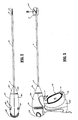
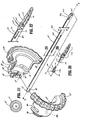
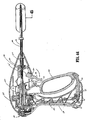
- an endoscopic bipolar forceps 10 for use with various surgical procedures and generally includes a housing 20, a handle assembly 30, a rotating assembly 80, a trigger assembly 70 and an end effector assembly 100 which mutually cooperate to grasp, seal and divide tubular vessels and vascular tissue 420 ( Fig. 36 ).
- a bipolar forceps 10 for use in connection with endoscopic surgical procedures, the present disclosure may be used for more traditional open surgical procedures.
- the forceps 10 is described in terms of an endoscopic instrument, however, it is contemplated that an open version of the forceps may also include the same or similar operating components and features as described below.
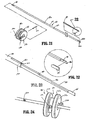
- Forceps 10 includes a shaft 12 which has a distal end 16 dimensioned to mechanically engage the end effector assembly 100 and a proximal end 14 which mechanically engages the housing 20. Details of how the shaft 12 connects to the end effector are described in more detail below with respect to Fig. 25 .
- the proximal end 14 of shaft 12 is received within the housing 20 and the connections relating thereto are described in detail below with respect to Figs. 13 and 14 .
- proximal as is traditional, will refer to the end of the forceps 10 which is closer to the user, while the term “distal” will refer to the end which is further from the user.
- forceps 10 also includes an electrosurgical cable 310 which connects the forceps 10 to a source of electrosurgical energy, e.g., a generator (not shown).
- a source of electrosurgical energy e.g., a generator (not shown).
- generators such as those sold by Valleylab - a division of Tyco Healthcare LP, located in Boulder Colorado are used as a source of electrosurgical energy, e.g., FORCE EZ TM Electrosurgical Generator, FORCE FX TM Electrosurgical Generator, FORCE 1C TM , FORCE 2 TM Generator, SurgiStat TM II.
- a source of electrosurgical energy e.g., a generator (not shown).
- generators such as those sold by Valleylab - a division of Tyco Healthcare LP, located in Boulder Colorado are used as a source of electrosurgical energy, e.g., FORCE EZ TM Electrosurgical Generator, FORCE FX TM Electrosurgical Generator, FORCE 1C TM , FORCE 2 TM Generator, S
- the generator includes various safety and performance features including isolated output, independent activation of accessories.
- the eiectrosurgical generator includes Valleylab's Instant ResponseTM technology features which provides an advanced feedback system to sense changes in tissue 200 times per second and adjust voltage and current to maintain appropriate power.
- the Instant ResponseTM technology is believed to provide one or more of the following benefits to surgical procedure:
- Cable 310 is internally divided into cable lead 310a, 310b and 310c which each transmit electrosurgical energy through their respective feed paths through the forceps 10 to the end effector assembly 100 as explained in more detail below with respect to Figs. 14 and 30 .
- Handle assembly 30 includes a fixed handle 50 and a movable handle 40.
- Fixed handle 50 is integrally associated with housing 20 and handle 40 is movable relative to fixed handle 50 as explained in more detail below with respect to the operation of the forceps 10.
- Rotating assembly 80 is preferably integrally associated with the housing 20 and is rotatable approximately 180 degrees in either direction about a longitudinal axis "A" (See Fig. 4 ). Details of the rotating assembly 80 are described in more detail with respect to Figs. 13 , 14 , 15 and 16
- housing 20 is formed from two (2) housing halves 20a and 20b which each include a plurality of interfaces 27a-27f which are dimensioned to mechanical align and engage one another to form housing 20 and enclose the internal working components of forceps 10.
- fixed handle 50 which, as mentioned above, is integrally associated with housing 20, takes shape upon the assembly of the housing halves 20a and 20b.
- housing halves 20a and 20b may be assembled together in any fashion known in the art.
- alignment pins, snap-like interfaces, tongue and groove interfaces, locking tabs, adhesive ports, etc. may all be utilized either alone or in combination for assembly purposes.
- Rotating assembly 80 includes two halves 82a and 82b which, when assembled, form the rotating assembly 80 which, in turn, houses the drive assembly 150 and the knife assembly 140 (See Figs. 13 , 14 and 25 ).
- Half 80a includes a series of detents/flanges 375a, 375b, 375c and 375d ( Fig. 25 ) which are dimensioned to engage a pair of corresponding sockets or other mechanical interfaces (not shown) disposed within rotating half 80a.
- Movable handle 40 and trigger assembly 70 are preferably of unitary construction and are operatively connected to the housing 20 and the fixed handle 50 during the assembly process.
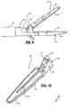
- end effector assembly 100 is attached at the distal end 14 of shaft 12 and includes a pair of opposing jaw members 110 and 120.
- Movable handle 40 of handle assembly 30 is ultimately connected to a drive assembly 150 which, together, mechanically cooperate to impart movement of the jaw members 110 and 120 from an open position wherein the jaw members 110 and 120 are disposed in spaced relation relative to one another, to a clamping or closed position wherein the jaw members 110 and 120 cooperate to grasp tissue 420 ( Fig. 36 ) therebetween.
- the forceps 10 may be designed such that it is fully or partially disposable depending upon a particular purpose or to achieve a particular result.
- end effector assembly 100 may be selectively and releasably engageable with the distal end 16 of the shaft 12 and/or the proximal end 14 of shaft 12 may be electively and releasably engageable with the housing 20 and the handle assembly 30.
- the forceps 10 would be considered "partially disposable" or "reposable", i.e., a new or different end effector assembly 100 (or end effector assembly 100 and shaft 12) selectively replaces the old end effector assembly 100 as needed.
- the presently disciosed electrical connections would have to be altered to modify the instrument to a reposable forceps.
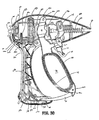
- movable handle 40 include a finger loop 41 which has an aperture 42 defined therethrough which enables a user to grasp and move the handle 40 relative to the fixed handle 50.
- Handle 40 also includes an ergonomically-enhanced gripping element 43 disposed along the inner peripheral edge of aperture 42 which is designed to facilitate gripping of the movable handles 40 during activation. It is envisioned that gripping element 43 may include one or more protuberances, scallops and/or ribs to enhance gripping. As best seen in Fig.
- movable handle 40 is selectively movable about a pair of pivot pins 29a and 29b from a first position relative to fixed handle 50 to a second position in closer proximity to the fixed handle 50 which, as explained below, imparts movement of the jaw members 110 and 120 relative to one another.
- the movable handle include a clevis 45 which forms a pair of upper flanges 45a and 45b each having an aperture 49a and 49b, respectively, at an upper end thereof for receiving the pivot pins 29a and 29b therethrough and mounting the upper end of the handle 40 to the housing 20.
- each pin 29a and 29b mounts to a respective housing half 20a and 20b.
- Each upper flange 45a and 45b also includes a force-actuating flange or drive flange 47a and 47b, respectively, which are aligned along longitudinal axis "A" and which abut the drive assembly 150 such that pivotal movement of the handle 40 forces actuating flange against the drive assembly 150 which, in turn, closets the jaw members 110 and 120.
- 47a and 47b which act simultaneously on the drive assembly are referred to as “driving flange 47".
- the lower end of the movable handle 40 includes a flange 90 which is preferably mounted to the movable handle 40 by pins 94a and 94b which engage a corresponding pair of apertures 91a and 91b disposed within the lower portion of handle 40 and apertures 97a and 97b disposed within flange 90, respectively.
- Flange 90 also includes a t-shaped distal end 95 which rides within a predefined channel 51 disposed within fixed handle 50 to lock the movable handle 40 relative to the fixed handle 50. Additional features with respect to the t-shaped end 95 are explained below in the detailed discussion of the operational features of the forceps 10.
- Movable handle 40 is designed to provide a distinct mechanical advantage over conventional handle assembles due to the unique position of the pivot pins 29a and 29b (i.e., pivot point) relative to the longitudinal axis "A" of the shaft 12 and the disposition of the driving flange 47 along longitudinal axis "A".
- pivot pins 29a and 29b i.e., pivot point
- the user gains lever-like mechanical advantage to actuate the jaw members 110 and 120 enabling the user to close the jaw members 110 and 120 with lesser force white still generating the required forces necessary to effect a proper and effective tissue seal.
- the unilateral design of the end effector assembly 100 will also increase mechanical advantage as explained in more detail below.
- the end effector assembly 100 includes opposing jaw members 110 and 120 which cooperate to effectively grasp tissue 420 for sealing purposes.
- the end effector assembly 100 is designed as a unilateral assembly, i.e., jaw member 120 is fixed relative to the shaft 12 and jaw member 110 pivots about a pivot pin 103 to grasp tissue 420.
- the unilateral end effector assembly 100 includes one stationary or fixed jaw member 120 mounted in fixed relation to the shaft 12 and pivoting jaw member 110 mounted about a pivot pin 103 attached to the stationery jaw member 120.
- a reciprocating sleeve 60 is slidingly disposed within the shaft 12 and is remotely operable by the drive assembly 150.
- the pivoting jaw member 110 incudes a detent or protrusion 117 which extends from jaw member 110 through an aperture 62 disposed within the reciprocating sleeve 60 ( Fig. 12 ).
- the pivoting jaw member 110 is actuated by sliding the sleeve 60 axially within the shaft 12 such that a distal end 63 of the aperture 62 abuts against the detent 117 on the pivoting jaw member 110 (See Figs. 11 and 12 ). Pulling the sleeve 60 proximally closes the jaw members 110 and 120 about tissue 420 grasped therebetween and pushing the sleeve 60 distally opens the jaw members 110 and 120 for grasping purposes.
- a knife channel 115a and 115b runs through the center of the jaw members 110 and 120, respectively, such that a blade 185 from the knife assembly 140 can cut the tissue 420 grasped between the jaw members 110 and 120 when the jaw members 110 and 120 are in a closed position. More particularly, the blade 185 can only be advanced through the tissue 420 when the jaw members 110 and 120 are closed thus preventing accidental or premature activation of the blade 185 through the tissue 420. Put simply, the knife channel 115 (made up of half channels 115a and 115b) is blocked when the jaws members 110 and 120 are opened and aligned for distal activation when the jaw members 110 and 120 are closed (See Figs. 35 and 39 ).
- the unilateral end effector assembly 100 may be structured such that electrical energy can be routed through the sleeve 60 at the protrusion 117 contact point with the sleeve 60 or using a "brush" or lever (not shown) to contact the back of the moving jaw member 110 when the jaw member 100 doses, ln this instance, the electrical energy would be routed through the protrusion 117 to the stationary jaw member 120.
- the cable lead 311 may be routed to energize the stationary jaw member 120 and the other electrical potential may be conducted through the sleeve 60 and transferred to the pivoting jaw member 110 which establishes electrical continuity upon retraction of the sleeve 60.
- this particular envisioned embodiment will provide at least two important safety features: 1) the blade 185 cannot extend while the jaw members 110 and 120 are opened; and 2) electrical continuity to the jaw members 110 and 120 is made only when the jaw members are closed.
- the illustrated forceps 10 only incudes the novel knife channel 115.
- jaw member 110 also includes a jaw housing 116 which has an insulative substrate or insulator 114 and an electrically conducive surface 112, Insulator 114 is preferably dimensioned to securely engage the electrically conductive sealing surface 112. This may be accomplished by stamping, by overmolding, by overmolding a stamped electrically conductive sealing plate and/or by overmolding a metal injection molded seal plate.
- the electrically conductive sealing plate 112 includes a series of upwardly extending flanges 111a and 111b which are designed to matingly engage the insulator 114.
- the insulator 114 includes a shoe-like interface 107 disposed at a distal end thereof which is dimensioned to engage the outer periphery 116a of the housing 116 in a slip-fit manner.
- the shoe-like interface 107 may also be overmolded about the outer periphery of the jaw 110 during a manufacturing step. It is envisioned that lead 311 terminates within the shoe-like interface 107 at the point where lead 311 electrically connects to the seal plate 112 (not shown).
- the movable jaw member 110 also includes a wire channel 113 which is designed to guide cable lead 311 into electrical continuity with seating plate 112 as described in more detail below.
- jaw member 110 halving an electrically conductive surface 112 which is substantially surrounded by an insulating substrate 114.
- the insulator 114, electrical conductive seating surface 112 and the outer, non-conductive jaw housing 116 are preferably dimensioned to limit and/or reduce many of the known undesirable effects related to tissue sealing, e.g., flashover, thermal spread end stray current dissipation.
- the jaw members 110 and 120 may be manufactured from a ceramic-like material and the electrically conductive surface(s) 112 are coated onto the ceramic-like jaw members 110 and 120.
- Jaw member 110 includes a pivot flange 118 which incudes protrusion 117.
- Protrusion 117 extends from pivot flange 118 and indues an arcuately-shaped inner surface 111 dimensioned to matingly engage the aperture 62 of sleeve 60 upon retraction thereof.
- Pivot flange 118 also includes a pin slot 119 which is dimensioned to engage pivot pin 103 to allow jaw member 110 to rotate relative to jaw member 120 upon retraction of the reciprocating sleeve 60.
- pivot pin 103 also mounts to the stationary jaw member 120 through a pair of apertures 101a and 101b disposed within a proximal portion of the jaw member 120.
- the electrically conductive sealing surface 112 may also include an outer peripheral edge which has a pre-defined radius and the insulator 114 meets the electrically conductive sealing surface 112 along an adjoining edge of the sealing surface 112 in a generally tangential position. Preferably, at the interface, the electrically conductive surface 112 is raised relative to the insulator 114.
- the electrically conductive surface 112 and the insulator 114 when assembled, form a longitudinally-oriented slot 115a defined therethrough for reciprocation of the knife blade 185.
- the knife channel 115a cooperates with a corresponding knife channel 115b defined in stationary jaw member 120 to facilitate longitudinal extension of the knife blade 185 along a preferred cutting plane to effectively and accurately separate the tissue 420 along the formed tissue seal 450 (See Figs. 42 and 46 ).
- Jaw member 120 includes similar elements to jaw member 110 such as jaw housing 126 having an insulator 124 and an electrically conductive sealing surface 122 which is dimensioned to securely engage the insulator 124.
- the electrically conductive surface 122 and the insulator 124 when assembled, include a longitudinally-oriented channel 115a defined therethrough for reciprocation of the knife blade 185.
- knife channels 115a and 115b form a complete knife channel 115 to allow longitudinal extension of the knife 185 in a distal fashion to sever tissue 420 along the tissue seal 450.
- the knife channel 115 may be completely disposed in one of the two jaw members, e.g., jaw member 120.
- the fixed jaw member 120 may be assembled in a similar manner as described above with respect to jaw member 110.
- jaw member 120 includes a series of stop members 750 preferably disposed on the inner facing surfaces of the electrically conductive sealing surface 122 to facilitate gripping and manipulation of tissue and to define a gap "G" ( Fig. 24 ) between opposing jaw members 110 and 120 during sealing and cutting of tissue. It is envisioned that the series of stop members 750 may be employed on one or both jaw members 110 and 120 depending upon a particular purpose or to achieve a desired result.
- stop members 750 as well as various manufacturing and assembling processes for attaching and/or affixing the stop members 750 to the electrically conductive sealing surfaces 112, 122 are described in commonly-assigned, co-pending U.S. Application Serial Ho. PCT/US01/11413 entitled "VESSEL SEALER AND DIVIDER WITH NON-CONDUCTIVE STOP MEMBERS" by Dycus et al. which is hereby referred to.
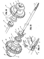
- Jaw member 120 is designed to be fixed to the end of a rotating tube 160 which is part of the rotating assembly 80 such that rotation of the tube 180 will impart rotation to the end effector assembly 100 (See Figs. 25 and 27 ).
- Jaw member 120 includes a rear C-shaped cuff 170 having a slot 177 defined therein which is dimensioned to receive a slide pin 171.
- slide pin 171 includes a slide rail 176 which extends substantially the length thereof which is dimensioned to slide into friction-fit engagement within slot 177.
- a pair of chamfered plates 172a and 172b extend generally radially from the slide rail 176 and include a radius which is substantially the same radius as the outer periphery of the rotating tube 160 such that the shaft 12 can encompass each of the same upon assembly.
- fixed jaw member 120 is connected to a second electrical potential through tube 160 which is connected at its proximal end to lead 310c. More particularly, fixed jaw 120 is welded to the rotating tube 160 and includes a fuse clip, spring clip or other electromechanical connection which provides electrical continuity to the fixed jaw member 120 from lead 310c (See Fig. 32 ). As best shown in Figs. 25 and 26 , the rotating tube 160 includes an elongated guide slot 167 disposed in an upper portion thereof which is dimensioned to carry lead 311 therealong. The chamfered plates 172a and 172b also form a wire channel 175 which is dimensioned to guide the cable lead 311 from the tube 160 and into the movable jaw member 110 (See Fig. 8 ). Lead 311 carries a first electrical potential to movable jaw 110. As explained in more detail below with respect to the internal electrical connections of the forceps, a second electrical connection from lead 310c is conducted through the tube 160 to the fixed jaw member 120.
- the distal end of the tube 160 is generally C-shaped to include two upwardly extending flanges 162a and 162b which define a cavity 165 for receiving the proximal end of the fixed jaw member 120 inclusive of C-shaped cuff 170 and slide pin 171 (See Fig. 27 ).
- the tube cavity 165 retains and secures the jaw member 120 in a friction-fit manner, however, the jaw member 120 may be welded to the tube 160 depending upon a particular purpose.
- Tube 160 also includes an inner cavity 169 defined therethrough which reciprocates the knife assembly 140 upon distal activation thereof and an elongated guide rail 163 which guides the knife assembly 140 during distal activation. The details with respect to the knife assembly are explained in more detail with respect to Figs. 21-24 .
- the proximal end of tube 160 includes a laterally oriented slot 168 which is designed to interface with the rotating assembly 80 as described below.
- Fig. 25 also shows the rotating assembly 80 which includes C-shaped rotating halves 82a and 82b which, when assembled about tube 160, form a generally circular rotating member 82. More particularly, each rotating half, e.g., 82b, includes a series, of mechanical interfaces 375a, 375b, 375c and 375d which matingly engage a corresponding series of mechanical interfaces in half 82a to form rotating member 82.
- Half 82b also includes a tab 89b which together with a corresponding tab 89a disposed on half 82a (phantomly illustrated) cooperate to matingly engage slot 168 disposed on tube 160.
- this permits selective rotation of the tube 160 about axis "A" by manipulating the rotating member 82 in the direction of the arrow "B" (see Fig. 4 ).
- jaw members 110 and 120 are pivotally mounted with respect to one another such that jaw member 110 pivots in a unilateral fashion from a first open position to a second doused position for grasping and manipulating tissue 420.
- fixed jaw member 120 includes a pair of proximal, upwardly extending flanges 125a and 125b which define a cavity 121 dimensioned to receive flanges 118 of movable jaw member 110 therein.
- Each of the flanges 125a and 125b includes an aperture 101a and 101b, respectively, defined therethrough which secures pivot pin 103 on opposite sides of pivot mount 119 disposed within jaw member 110.
- proximal movement of the tube 60 engages detent 117 to pivots the jaw member 110 to a closed position.
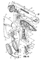
- Figs. 13 and 14 show the details of the housing 20 and the component features thereof, namely, the drive assembly 150, the rotating assembly 80, the knife assembly 140, the trigger assembly 70 and the handles 40 and 50. More particularly, Fig. 13 shows the above-identified assembles and components in an assembled form in the housing 20 and Fig. 14 shows an exploded view of teach of the above-identified assembles and components.
- the housing includes halves 20a and 20b which, when mated, form housing 20.
- housing 20 once formed, houses the various assemblies identified above which will enable a user to selectively manipulate, grasp, seal and sever tissue 420 in a simple, effective, and efficient manner.
- each half of the housing e.g., half 20b, includes a series of mechanical interfacing component, e.g., 27a - 27f which align and/or mate with a corresponding series of mechanical interfaces (not shown) to align the two housing halves 20a and 20b about the inner components and assemblies.
- the housing halves 20a and 20b are then preferably, sonic welded to secure the housing halves 20a and 20b once assembled.
- the movable handle 40 incudes clevis 45 which forms upper flanges 45a and 45b which pivot about pins 29a and 29b to pull the reciprocating sleeve 60 along longitudinal axis "A" and force during flange 47 against the drive assembly 150 which, in turn, closes the jaw members 110 and 120.
- the lower end of the movable handle 40 includes a flange 90 which has a t-shaped distal end 95 which rides within a predefined channel 51 disposed within fixed handle 50 to lock the movable handle 40 in a preset orientation relative to the fixed handle 50.
- the arrangement of the upper flanges 45a and 45b and the pivot point of the moveable handle 40 provides a distinct mechanical advantage over conventional handle assemblies due to the unique position of the pivot pins 29a and 29b (i.e., pivot point) relative to the longitudinal axis "A" of the driving flange 47.
- the pivot pins 29a and 29b i.e., pivot point
- the user gains lever-like mechanical advantage to actuate the jaw members 110 and 120. This reduces the overall amount of mechanical force necessary to close the jaw members 110 and 120 to effect a tissue seal.
- Handle 40 also includes a finger loop 41 which defines opening 42 which is dimensioned to facilitate grasping the handle 40.
- finger loop 41 includes rubber insert 43 which enhances the overall ergonomic "feel" of the handle member 40.
- a locking flange 44 is disposed on the outer periphery of the handle member 40 above the finger loop 41. Locking flange 44 presents the trigger assembly 70 from firing when the handle member 40 is oriented in a non-actuated position, i.e., the jaw members 110 and 120 are open. As can be appreciated, this prevents accidental or premature severing of tissue 420 prior to completion of the tissue seal 450.
- Fixed handle 50 includes halves 50a and 50b which, when assembled, form handle 50.
- Fixed handle 50 includes a channel 51 defined therein which is dimensioned to receive flange 90 in a proximal moving manner when movable handle 40 is actuated.
- the t-shaped free end 95 of handle 40 is dimensioned for facile reception within channel 51 of handle 50.
- flange 90 may be dimensioned to allow a user to selectively, progressively and/or incremental move jaw members 110 and 120 relative to one another from the open to closed positions.
- flange 90 may include a ratchet-like interface which mockingly engages the movable handle 40 and, therefore, jaw members 110 and 120 at selective, incremental positions relative to one another depending upon a particular purpose.
- Other mechanisms may also be employed to control and/or limit the movement of handle 40 relative to handle 50 (and jaw members 110 and 120) such as, e.g., hydraulic, semi-hydraulic, iinear actuator(s), gas-assisted mechanisms and/or gearing systems.
- housing halves 20a and 20b when assembled form an internal cavity 52 which predefines the channel 51 within fixed handle 50 such that an entrance pathway 54 and an exit pathway 58 are formed for reciprocation of the t-shaped flange end 95 therein.
- two generally triangular-shaped members 57 are positioned in close abutment relative to one another to define a rail or track 192 therebetween.
- the t-shaped end 95 rides along track 192 between the two triangular members 57 according to the particular dimensions of the triangularly-shaped members 57, which, as can be appreciated, predetermines part of the overall pivoting motion of handle 40 relative to fixed handles 50.
- handle 40 moves in a generally arcuate fashion towards fixed handle 50 about pivot pins 29a and 29b which forces driving flange 47 proximally against the drive assembly 150 which, in turn, pulls reciprocating sleeve 60 in a generally proximal direction to close jaw member 110 relative to jaw member 120.
- proximal rotation of the handle 40 causes the locking flange 44 to release, i.e., "unlock", the trigger assembly 70 for selective actuation.
- This feature is shown in detail with reference to Figs. 33 , 37 and 44 and the explanation of the operation of the knife assembly 70 explained below.
- the operating features and relative movements of the internal working components of the forceps 10 are shown by phantom representation in the various figures.
- a predefined channel 52 is formed within the fixed handle 50.
- the channel includes entrance pathway 51 and an exit pathway 58 for reciprocation of the flange 90 and the t-shaped end 95 therein.
- the two generally triangular-shaped members 57 are positioned in close abutment relative to one another and define track 192 disposed therebetween.
- the driving flange 47 biases flange 154 of drive ring 159 which, in turn, compresses a spring 67 against a rear ring 156 of the drive assembly 150 ( Fig. 40 ).
- the rear ring 156 reciprocates sleeve 60 proximally which, in turn, closes jaw member 110 onto jaw member 120.
- Figs. 37 and 38 show the initial actuation of handle 40 towards fired handle 50 which causes the free end 95 of flange 90 to move generally proximally and upwardly along entrance pathway 51.
- the t-shaped end 95 rides along track 192 between the two triangular members 57.
- the jaw members 110 and 120 may be opened, closed and rotated to manipulate tissue 420 until sealing is desired. This enables the user to position and re-position the forceps 10 prior to activation and sealing.
- the end effector assembly 100 is rotatable about longitudinal axis "A" through rotation of the rotating assembly 80.
- the unique feed path of the cable lead 311 through the rotating assembly 80, along shaft 12 and, ultimately, to the jaw member 110 enables the user to rotate the end effector assembly 100 about 180 degrees in both the clockwise and counterclockwise direction without tangling or causing undue strain on cable lead 311.
- Cable lead 310c is fused or clipped to the proximal end of tube 160 and is generally unaffected by rotation of the jaw members 110. and 120. As can be appreciated, this facilitates the grasping and manipulation of tissue 420.
- trigger assembly 70 mounts atop movable handle 40 and cooperates with the knife assembly 140 to selectively translate knife 185 through a tissue seal 450. More particularly, the trigger assembly 70 includes a finger actuator 71 and a U-shaped upwardly-extending flange 74 having legs 74a and 74b. A pivot pin 73 mounts the trigger assembly 70 between housing halves 20a and 20b for selective rotation thereof. A pair of safety tabs 76a and 76b are disposed atop finger actuator 71 and are dimensioned to abut the locking flange 44 on handle 40 when the handle 40 is disposed in as non-actuated position, i.e., the jaw members 110 and 120 are opened.
- the legs 74a and 74b of the U-shaped flange 74 each include a respective slot 77a and 77b defined therein which are each dimensioned to receive a free end of an elongated drive bar 75.
- Drive bar 75 is dimensioned to sit within a drive slot 147 which is part of the knife assembly 140 explained in detail below.
- the trigger assembly 70 is mounted atop the donut-like drive ring 141 of the knife assembly 140. Proximal activation of the finger actuator 71 rotates the trigger assembly 70 about pivot pin 73 which, in turn, forces the drive bar 75 distally, which, as explained in more detail below, ultimately extends the knife 185 through the tissue 420.
- a spring 350 biases the knife assembly 70 in a retracted position such that after severing tissue 420 the knife 185 and the knife assembly 70 are automatically returned to a pre-firing position.
- the locking flange 44 abuts tabs 76a and 76b when the handle 40 is disposed in a non-actuated position.
- the locking flange 44 moves proximally allowing activation of the trigger assembly 70 (See Figs. 37 and 44 ).
- Drive assembly 150 includes reciprocating sleeve 60, drive housing 158, spring 67, drive ring 159, drive stop 155 and guide sleeve 157 which all cooperate to form the drive assembly 150. More particularly and as best shown in Figs. 28 and 29 , the reciprocating sleeve 60 includes a distal end 65 which as mentioned above has an aperture 62 formed therein for actuating the detent 117 of jaw member 110. The distal end 65 preferably includes a scoop-like support member 69 for supporting the proximal end of the fixed jaw member 120 therein.
- the proximal end 61 of the reciprocating sleeve 60 includes a slot 68 defined therein which is dimensioned to slidingly support the knife assembly 70 for longitudinal reciprocation thereof to sever tissue 420.
- the slot 68 also permits retraction of the reciprocating sleeve 60 over the knife assembly 140 during the closing of jaw member 110 relative to jaw member 120.
- the proximal end 61 of the reciprocating sleeve 60 is positioned within an aperture 151 in drive housing 158 to permit selective reciprocation thereof upon actuation of the movable handle 40.
- the spring 67 is assembled atop the drive housing 158 between a rear stop 156 of the drive housing 158 and a forward stop 154 of the drive ring 159 such that movement of the forward stop 154 compresses the spring 67 against the rear stop 156 which, in turn, reciprocates the drive sleeve 60.
- the jaw members 10 and 120 and the movable handle 40 are biased by spring 67 in an open configuration.
- the drive stop 155 is fixedly positioned atop the drive housing 158 and biases the upper flange 458 and 45b of the movable handle 40 when actuated such that the driving flange 47 forces the stop 154 of the drive ring 159 proximally against the force of the spring 67.
- the spring 67 forces the rear stop 156 proximally to reciprocate the sleeve 60 (See Fig. 40 ).
- the rotating assembly 80 is located proximate the driving flange 47 to facilitate rotation of the end effector assembly 100.
- the guide sleeve 157 mates with the proximal end 61 of the reciprocating sleeve 60 and affixes to the drive housing 158.
- the assembled drive assembly 150 is shown best in Fig. 20 .
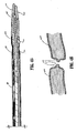
- the knife assembly 140 includes an elongated rod 182 having a bifurcated distal end comprising prongs 182a and 182b which cooperate to receive a knife bar 184 therein.
- the knife assembly 180 also includes a proximal end 183 which is keyed to facilitate insertion into tube 160 of the rotating assembly 80.
- a knife wheel 148 is secured to the knife bar 182 by a pin 143.
- the elongated knife rod 182 includes apertures 181a and 181b which are dimensioned to receive and secure the knife wheel 148 to the knife rod 182 such that longitudinal reciprocation of the knife wheel 148, in turn, moves the elongated knife rod 182 to sever tissue 420.
- the knife wheel 148 is preferably donut-like and incudes rings 141a and 141b which define a drive slot 147 designed to receive the drive bar 75 of the trigger assembly 70 such that proximal actuation of the trigger assembly 70 forces the drive bar 75 and the knife wheel 148 dismally. It is envisioned that aperture 181a may be used for a particular trigger assembly 70 configuration and aperture 181b may be used for a different trigger assembly 70 configuration. As such, pin 143 is designed for attachment through either aperture 181a or 181b to mount the knife wheel 148 (See Fig. 24 ). Knife wheel 148 also includes a series of radial flanges 142a and 142b which are dimensioned to side along both channel 163 of tube 160 and slot 68 of the reciprocating sleeve 60 (See Fig. 15 ).
- the knife rod 182 is dimensioned to mount the knife bar 184 between prongs 182a and 182b preferably in friction-fit engagement.
- the knife bar 184 incudes a series of steps 186a, 186b and 186c which reduce the profile of the knife bar 184 towards the distal end thereof.
- the distal end of the knife bar 184 includes a knife support 188 which is dimensioned to retain knife blade 185.
- the end of the knife support preferably includes a chamfered edge 188a. It is envisioned that the knife blade 185 may be welded to the knife support 188 of secured in any manner known in the trade.
- the electrical leads 310a, 310b, 310c and 311 are fed through the housing 20 by electrosurgical cable 310. More particularly, the electrosurgical cable 310 is fed into the bottom of the housing 20 through fixed handle 50. Lead 310c extends directly from cable 310 into the rotating assembly 80 and connects (via a fused clip or spring clip or the like) to tube 60 to conduct the second electrical potential to fixed jaw member 120. Leads 310a and 310b extend from cable 310 and connect to the hand switch or joy-stick-like toggle switch 200.
- Switch 200 includes an ergonomically dimensioned toggle plate 205 having a pair of wings 207a and 207b which preferably conform to the outer shape of housing 20 (once assembled). It is envisioned that the switch 200 permits the user to selectively activate the forceps 10 in a variety of different orientations, i.e., multi-oriented activation. As can be appreciated, this simplifies activation.
- a pair of prongs 204a and 204b extend distally and mate with a corresponding pair of mechanical interfaces 21a and 21b disposed within housing 20 (See Fig. 32 ). Prongs 204a and 204b preferably snap-fit to the housing 20 during assembly.
- Toggle plate 205 also includes a switch interface 203 with mates with a switch button 202 which, in turn, connects to electrical interface 201.
- the electrical leads 310a and 310b are electrically connected to electrical interface 201.
- trigger lead 311 carries the first electrical potential to jew member 110. More particularly, lead 311 extends from interface 201 through a plurality of slots 84a, 84b and 84c of the rotating assembly 80 (See Figs. 25 and 30 ) and alone the upper portion of tube 160 and eventually connects to the movable jaw member 110 as described above (See Figs. 32 , 34 and 35 ).
- a safety switch or circuit (not shown) may be employed such that the switch cannot fire unless the jaw members 110 and 120 are closed and/or unless the jaw members 110 and 120 have tissue 420 held therebetween.
- a sensor (not shown) may be employed to determine if tissue 420 is held therebetween.
- other sensor mechanisms may be employed which determine pre-surgical, concurrent surgical (i.e., during surgery) and/or post surgical conditions. The sensor mechanisms may also be utilized with a closed-loop feedback system coupled to the electrosurgical generator to regulate the electrosurgical energy based upon one or more pre-surgical, concurrent surgical or post surgical conditions.
- each jaw member, e.g., 110 includes a uniquely-designed electrosurgical cable path disposed therethrough which transmits electrosurgical energy to the electrically conductive sealing surface 112.
- jaw member 110 may include one or more cable guides or crimp-like electrical connectors to direct cable lead 311 towards electrically conductive sealing surface 112.
- cable lead 311 is held loosely but securely along the cable path to permit rotation of the jaw member 110 about pivot 103.
- the second electrical potential is conducted to jaw member 120 through tube 160.
- the two potentials are isolated from one another by virtue of the insulative sheathing surrounding cable lead 311.
- utilizing a cable feed path for cable lead 311 and by utilizing a conductive tube 160 to carry the first and second electrical potentials not only electrically isolates each jaw member 110 and 120 but also allows the jaw members 110 and 120 to pivot about pivot pin 103 without unduly straining or possibly tangling cable lead 311.
- the simplicity of the electrical connections greatly facilitates the manufacturing and assembly process and assures a consistent and tight electrical connection for the transfer of energy through the tissue 420.
- each cable lead 311 and 310c is fed through a series of conjoining slots 84a, 84b, 84c and 84d located in the two halves 82a and 82b of the rotating assembly 80.
- each conjoining pair of slots e.g., 84a, 84b and 84c, 84d, are large enough to permit rotation of the rotating assembly 80 without unduly straining or tangling the cable leads 311 and 310c.
- the presently disclosed cable lead feed path is envisioned to allow rotation of the rotation assembly approximately 180 degrees in either direction.
- Fig. 14 which shows the exploded view of the housing 20, rotating assembly 80, trigger assembly 70, movable handle 40 and fixed handle 50, it is envisioned that all of these various component parts along with the shaft 12 and the end effector assembly 100 are assembled during the manufacturing process to form a partially and/or fully disposable forceps 10.
- the shaft 12 and/or end effector assembly 100 may be disposable and, therefore, selectively/releasably engagable with the housing 20 and rotating assembly 80 to form a partially disposable forceps 10 and/or the entire forceps 10 may be disposable after use.
- spring 67 is poised for compression atop drive housing 158 upon actuation of the movable handle 40. More particularly, movement of the handle 40 about pivot pins 29a and 29b reciprocates the flange 90 into fixed handle 50 and forces drive flange 47 against flange 154 of drive ring 159 to compress spring 67 against the rear stop 156 to reciprocate the sleeve 60 (See Fig. 40 ).
- the trigger assembly 70 is initially prevented from firing by the locking flange 44 disposed on movable handle 40 which abuts against the trigger assembly 70 prior to actuation, It is envisioned that the opposing jaw members 110 and 120 may be rotated and partially opened and closed without unlocking the trigger assembly 70 which, as can be appreciated, allows the user to grip and manipulate the tissue 420 without premature activation of the knife assembly 140. As mentioned below, only when the t-shaped end 95 of flange 90 is completely reciprocated within channel 51 of the fixed handle 50 and seated within pre-defined catch basin 194 will the locking flange allow activation of the trigger assembly 70. The operating features and relative movements of these internal working components of the forceps 10 are shown by phantom representation and directional arrows and are best illustrated in Figs. 36-49 .
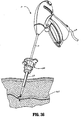
- Fig. 36 shows the forceps approximating tissue.
- the drive flange 47 through the mechanical advantage of the over the center pivot pins 29a and 29b is rotated generally proximally to compress spring 67.
- the reciprocating sleeve 60 is pulled proximally by the movement of rear ring 156 which, in turn, causes aperture 62 of sleeve 60 to proximally cam detent 117 and close the jaw member 110 relative to jaw member 120 (See Figs. 37-40 ).
- the mechanical advantage of the over-the-center pivot will enable the user to selectively compress the coil spring 67 a specific distance which, in turn, imparts a specific load on the reciprocating sleeve 60.
- the reciprocating sleeve's 60 load is converted to a torque about the jaw pivot 103.
- a specific closure force can be transmitted to the opposing jaw members 110 and 120.
- the jaw members 110 and 120 may be opened, closed and rotated to manipulate tissue 420 until sealing is desired without unlocking the trigger assembly 70. This enables the user to position and re-position the forceps 10 prior to activation and sealing. More particularly, as illustrated in Fig. 4 , the end effector assembly 100 is rotatable about longitudinal axis "A" through rotation of the rotating assembly 80.
- handle 40 may be compressed fully such that the t-shaped end 95 of flange 90 clears a predefined rail edge 193 located atop the triangular-shaped members 57. Once end 95 clears edge 193, the end is directed into catch basin 194 located within the exit pathway 58. More particularly, upon a slight reduction in the closing pressure of handle 40 against handle 50, the handle 40 returns slightly distally towards entrance pathway 54 but is re-directed towards exit pathway 58 into catch basin 194 (See Fig. 38 ).
- end effector assembly 100 and/or the jaw members 110 and 120 may be dimensioned to off-load some of the excessive clamping forces to prevent mechanical failure of certain internal operating elements of the end effector 100.
- the combination of the mechanical advantage of the over-the-center pivot along with the compressive force associated with the compression spring 67 facilitate and assure consistent, uniform and accurate closure pressure about the tissue 420 within the desired working pressure range of about 3 kg/cm 2 to about 16 kg/cm 2 and, preferably, about 7 kg/cm 2 to about 13 kg/cm 2 ,
- the user can either cauterize, coagulate/desiccate, seal and/or simply reduce or slow bleeding.
- Applying the correct force is also important for other reasons: to oppose the walls of the vessel; to reduce the tissue impedance to a low enough value that allows enough current through the tissue 420; and to overcome the forces of expansion during, tissue heating in addition to contributing towards creating the required end tissue thickness which is an indication of a good seal 450.
- the electrically conductive sealing surfaces 112, 122 of the jaw members 110, 120 are relatively flat to avoid current concentrations at sharp edges and to avoid arcing between high points.
- jaw members 110 and 120 are preferably manufactured to resist bending.
- the jaw members 110 and 120 may be tapered along the width thereof which is advantageous for two reasons: 1) the taper will apply constant pressure for a constant tissue thickness at parallel; 2) the thicker proximal portion of the jaw members 110 and 120 will resist bending due to the reaction force of the tissue 420.
- At least one jaw member may include a stop member 750 which limits the movement of the two opposing jaw members 110 and 120 relative to one another.
- the stop member 750 extends from the sealing surface 122 a predetermined distance according to the specific material properties (e.g., compressive strength, thermal expansion, etc.) to yield a consistent and accurate gap distance "G" during sealing ( Fig. 41 ).
- the gap distance between opposing sealing surfaces 112 and 122 during sealing ranges from about 0,00254 cm (0.001 inches) to about 0,01524 cm (0.006 inches) and, more preferably, between about 0,80508 cm and about 0,00762 cm (0.002 and about 0.003 inches).
- the non-conductive stop members 750 are molded onto the jaw members 110 and 120 (e.g., overmolding, injection molding, etc.), stamped onto the jaw members 110 and 120 or deposited (e.g., deposition) onto the jaw members 110 and 120.
- one technique involves thermally spraying a ceramic material onto the surface of the jaw member 110 and 120 to form the stop members 750.
- thermal spraying techniques are contemplated which involve depositing a broad range of heat resistant and insulative materials on various surfaces to create stop members 750 for controlling the gap distance between electrically conductive surfaces 112 and 122.
- tissue seal 450 forms isolating two tissue halves 420a and 420b.
- the user must remove and replace the forceps 10 with a cutting instrument (not shown) to divide the tissue halves 420a and 420b along the tissue seal 450.
- a cutting instrument not shown
- Knife assembly 140 which, when activated via the trigger assembly 70, progressively and selectively divides the tissue 420 along an ideal tissue plane in precise manner to effectively and reliably divide the tissue 420 into two sealed halves 420a and 420b (See Fig. 46 ) with a tissue gap 475 therebetween.
- the knife assembly 140 allows the user to quickly separate the tissue 420 immediately after sealing without substituting a cutting instrument through a cannula or trocar port. As can be appreciated, accurate sealing and dividing of tissue 420 is accomplished with the same forceps 10.
- knife blade 185 may also be coupled to the same or an alternative electrosurgical energy source to facilitate separation of the tissue 420 along the tissue seal 450 (Not shown).
- the angle of the knife blade tip 185 may be dimensioned to provide more or less aggressive cutting angles depending upon a particular purpose.
- the knife blade 185 may be positioned at an angle which reduces "tissue wisps" associated with cutting. More over, the knife blade 185 may be designed having different blade geometries such as serrated, notched, perforated, hollow, concave, convex etc. depending upon a particular purpose or to achieve a particular result.
- the jaw members 110 and 120 may be opened by re-grasping the handle 40 as explained below. It is envisioned that the knife assembly 140 generally cuts in a progressive, uni-directional fashion (i.e., distally).
- re-initiation or re-grasping of the handle 40 again moves t-shaped end 95 of flanges 90 generally proximally along exit pathway 58 until end 95 clears a lip 196 disposed atop triangular-shaped members 57 along exit pathway 58.
- lip 196 is sufficiently cleared, handle 40 and flange 90 are fully and freely releasable from handle 50 alone, exit pathway 58 upon the reduction of grasping/gripping pressure which, in turn, returns the jaw members 110 and 120 to the open, pre-activated position.
- the forceps 10 may include a sensor or feedback mechanism (not shown) which automatically selects the appropriate amount of electrosurgical energy to effectively seal the particularly-sized tissue grasped between the jaw members 110 and 120.
- the sensor or feedback mechanism may also measure the impedance across the tissue during seating and provide an indicator (visual and/or audible) that an effective seal has been created between the jaw members 110 and 120. Examples of such sensor systems are described in commonly-owned U.S. Patent Application Serial No. 10/427,832 entitled "METHOD AND SYSTEM FOR CONTROLLING OUTPUT OF RF MEDICAL GENERATOR" filed on May 1, 2003 the entire contents of which are hereby referred to.
- the trigger assembly 70 may include other types of recoil mechanism which are designed to accomplish the same purpose, e.g., gas-actuated recoil, electrically-actuated recoil (i.e., solenoid), etc. It is also envisioned that the forceps 10 may be used to cut tissue 420 without sealing. Alternatively, the knife assembly 70 may be coupled to the same or alternate eiectrosurgical energy source to facilitate cutting of the tissue 420.
- the forceps 10 manipulating an isolated vessel 420
- the forceps 10 may be used with non-isolated vessels as well.
- Other cutting mechanisms are also contemplated to cut tissue 420 along the ideal tissue plane.
- the outer surface of the end effector assembly 100 may include a nickel-based material, coating, stamping, metal injection molding which is designed to reduce adhesion between the jaw members 110 and 120 with the surrounding tissue during activation and sealing.
- the conductive surfaces 112 and 122 of the jaw members 110 and 120 may be manufactured from one (or a combination of one or more) of the following materials; nickel-chrome, chromium nitride, MedCoat 2000 manufactured by The Electrolizing Corporation of OHIO, inconel 600 and tin-nickel.
- the tissue conductive surfaces 112 arid 122 may also be coated with one or more of the above materials to achieve the same result, i.e., a "non-stick surface".
- reducing the amount that the tissue "sticks" during sealing improves the overall efficacy of the instrument.
- nitride coatings which include, but not are not limited to: TilN, ZrN, TiAlN, and CrN are preferred materials used for non-stick purposes. CrN has been found to be particularly useful for non-stick purposes due to its overall surface properties and optimal performance. Other classes of materials have also been found to reducing overall sticking. For example, high nickel/chrome alloys with a Ni/Cr ratio of approximately 5:1 have been found to significantly reduce sticking in bipolar instrumentation.
- One particularly useful non-stick material in this class is Inconel 600. Bipolar instrumentation having sealing surfaces 112 and 122 made from or coated with Ni200, Ni201 ( ⁇ 100% Ni) also showed improved non-stick performance over typical bipolar stainless steel electrodes.
- the switch 200 reduces the amount of electrical cable in the operating room and eliminates the possibility of activating the wrong instrument during a surgical procedure due to "line-of-sight" activation. Moreover, decommissioning the switch 200 when the trigger is actuated eliminates unintentionally activating the device during the cutting process. It is also envisioned that the switch 200 may be disposed on another part of the forceps 10, e.g., the fixed handle 40, rotating assembly 80, housing 20, etc.
Landscapes
- Health & Medical Sciences (AREA)
- Surgery (AREA)
- Engineering & Computer Science (AREA)
- Life Sciences & Earth Sciences (AREA)
- Biomedical Technology (AREA)
- Otolaryngology (AREA)
- Nuclear Medicine, Radiotherapy & Molecular Imaging (AREA)
- Plasma & Fusion (AREA)
- Physics & Mathematics (AREA)
- Heart & Thoracic Surgery (AREA)
- Medical Informatics (AREA)
- Molecular Biology (AREA)
- Animal Behavior & Ethology (AREA)
- General Health & Medical Sciences (AREA)
- Public Health (AREA)
- Veterinary Medicine (AREA)
- Surgical Instruments (AREA)
Claims (9)
- Endoskopische bipolare Zange (10), mit:einem Gehäuse (20);einem an dem Gehäuse befestigten Schaft (12), der an seinem distalen Ende ein bewegbares Backenelement (110) und ein zweites Backenelement (120) aufweist, wobei der Schaft durch sich hindurch eine Längsachse definiert und das bewegbare Backenelement einen Drehflansch (118) mit einem sich von ihm erstreckenden Vorsprung (117) aufweist;wobei jedes Backenelement eingerichtet ist, sich mit einer Quelle elektrochirurgischer Energie zu verbinden, sodass die Backenelemente im Stande sind, Energie durch zwischen ihnen gehaltenes Gewebe zu leiten, um eine Gewebeversiegelung zu bewirken; undein gezielt vorschiebbarer Messeraufbau (140), der Gewebe entlang der Gewebeversiegelung in Vorwärtsrichtung schneidet;einem Antriebsaufbau (150), der eingerichtet ist, das bewegbare Backenelement relativ zu dem zweiten Backenelement zu bewegen, und zwar von einer ersten Position, in der das bewegbare Backenelement in einer beabstandeten Beziehung relativ zu dem zweiten Backenelement angeordnet ist, zu einer zweiten Position, in der das bewegbare Backenelement zum Bearbeiten von Gewebe näher an dem zweiten Backenelement ist,wobei das zweite Backenelement ein an dem distalen Ende des Schafts befestigtes Backenelement ist;der Antriebsaufbau durch einen bewegbaren Griff (40) betätigbar ist, um einen Antriebsflansch (47a, 47b) proximal um einen Antriebsdrehpunkt (29a, 29b) zu drehen, um eine sich hin- und herbewegende Hülse (60) proximal entlang der Längsachse zu bewegen, wobei die sich hin- und herbewegende Hülse an ihrem distalen Ende eine Öffnung (62) definiert, die mechanisch mit dem Vorsprung des Drehflansches von dem bewegbaren Backenelement zusammenwirkt, um eine festgelegte Schließkraft auf das bewegbare Backenelement auszuüben, der Antriebsdrehpunkt in einem festgelegten Abstand über der Längsachse in einer zu der Längsachse des Schafts im Wesentlichen senkrechten Richtung angeordnet ist, und ein Griffabschnitt des Griffs in einem festgelegten Abstand unter der Längsachse in einer zu der Längsachse des Schafts im Wesentlichen senkrechten Richtung angeordnet ist, dadurch gekennzeichnet, dass das feststehende Backenelement ein Paar proximaler sich nach oben erstreckende Flansche (125a, 125b) aufweist, die einen Hohlraum (121) definieren, der in sich den Drehflansch des bewegbaren Backenelements aufnimmt, wobei jeder der Flansche jeweils eine durch sich hindurch definierte Öffnung (101a, 101b) aufweist, die einen Drehstift (103) auf gegenüberliegenden Seiten einer Gelenkhalterung (119) des Drehflansches von dem bewegbaren Backenelement sichert und der Drehstift in die Gelenkhalterung eingreift, um dem bewegbaren Backenelement zu ermöglichen, sich relativ zu dem feststehenden Backenelement von der ersten Position zu der zweiten Position bei proximalem Rückzug der sich hin- und herbewegenden Hülse zu drehen,und des Weitern mit einer leitfähigen Röhre (160), die an dem feststehenden Backenelement (120) befestigt ist und durch den Schaft (12) hindurch zum Leiten eines elektrischen Potentials zu dem feststehenden Backenelement (120) angeordnet ist.
- Endoskopische Zange nach Anspruch 1, bei welcher der bewegbare Griff einen Sperrflansch (44) aufweist, der ausgelegt ist, ein gezieltes Vorschieben des Messeraufbaus zu verhindern, wenn der bewegbare Griff in einer ersten Position angeordnet ist und wobei der Sperrflansch des bewegbaren Griffs verstellt wird, um ein gezieltes Vorschieben des Messeraufbaus zuzulassen, wenn der bewegbare Griff sich zu einer zweiten Position dreht.
- Endoskopische bipolare Zange nach Anspruch 1, des Weiteren mit einem Drehaufbau (80), der im Betrieb im Stande ist, die Backenelemente um die durch den Schaft definierte Längsachse zu drehen.
- Endoskopische bipolare Zange nach Anspruch 1, des Weiteren mit einem Handschalter (200), der in dem Gehäuse angeordnet ist und elektromechanisch mit der Quelle elektrischer Energie zusammenwirkt, wobei der Handschalter im Betrieb im Stande ist, es einem Benutzer zu ermöglichen, gezielt bipolare Energie zu den Backenelementen zuzuführen, um die Gewebeversiegelung zu bewirken.
- Endoskopische bipolare Zange nach Anspruch 4, bei welcher der Handschalter proximal zu dem Griff angeordnet ist.
- Endoskopische bipolare Zange nach Anspruch 1, bei der das bewegbare Backenelement ein erstes elektrisches Potential aufweist und das feststehende Backenelement ein zweites elektrisches Potential aufweist.
- Endoskopische bipolare Zange nach Anspruch 1, bei der mindestens eines der Backenelemente mindestens ein Anschlagelement (750) an sich angeordnet aufweist, das eingerichtet ist, den Abstand zwischen den Backenelementen während des Versiegelns zu regeln.
- Endoskopische bipolare Zange nach Anspruch 1, bei der die festgelegte Schließkraft in einem Bereich von in etwa 3 kg/cm2 bis in etwa 16 kg/cm2 liegt.
- Endoskopische bipolare Zange nach Anspruch 1, bei der die sich hin- und herbewegende Hülse an einem distalen Ende ein löffelartiges Stützelement aufweist, und zwar um eines proximales Ende des feststehenden Backenelements darin zu unterstützen, wobei das löffelähnliche Stützelement die Öffnung (62) definiert.
Priority Applications (1)
| Application Number | Priority Date | Filing Date | Title |
|---|---|---|---|
| EP10172005.0A EP2246004B1 (de) | 2003-06-13 | 2003-06-13 | Gefässabdichtung und -trenner zur Verwendung in kleinen Trokaren und Kanülen |
Applications Claiming Priority (3)
| Application Number | Priority Date | Filing Date | Title |
|---|---|---|---|
| PCT/US2003/018674 WO2005004734A1 (en) | 2003-06-13 | 2003-06-13 | Vessel sealer and divider for use with small trocars and cannulas |
| EP10172005.0A EP2246004B1 (de) | 2003-06-13 | 2003-06-13 | Gefässabdichtung und -trenner zur Verwendung in kleinen Trokaren und Kanülen |
| EP03737062A EP1633264B1 (de) | 2003-06-13 | 2003-06-13 | Gefässversieglungs- und -trennungsgerät zur benutzung mit kleinem trokar und kannula |
Related Parent Applications (1)
| Application Number | Title | Priority Date | Filing Date |
|---|---|---|---|
| EP03737062.4 Division | 2003-06-13 |
Publications (2)
| Publication Number | Publication Date |
|---|---|
| EP2246004A1 EP2246004A1 (de) | 2010-11-03 |
| EP2246004B1 true EP2246004B1 (de) | 2013-08-07 |
Family
ID=34061422
Family Applications (2)
| Application Number | Title | Priority Date | Filing Date |
|---|---|---|---|
| EP10172005.0A Expired - Lifetime EP2246004B1 (de) | 2003-06-13 | 2003-06-13 | Gefässabdichtung und -trenner zur Verwendung in kleinen Trokaren und Kanülen |
| EP03737062A Expired - Lifetime EP1633264B1 (de) | 2003-06-13 | 2003-06-13 | Gefässversieglungs- und -trennungsgerät zur benutzung mit kleinem trokar und kannula |
Family Applications After (1)
| Application Number | Title | Priority Date | Filing Date |
|---|---|---|---|
| EP03737062A Expired - Lifetime EP1633264B1 (de) | 2003-06-13 | 2003-06-13 | Gefässversieglungs- und -trennungsgerät zur benutzung mit kleinem trokar und kannula |
Country Status (6)
| Country | Link |
|---|---|
| EP (2) | EP2246004B1 (de) |
| AU (2) | AU2003236505B2 (de) |
| CA (1) | CA2528918C (de) |
| DE (1) | DE60333799D1 (de) |
| ES (1) | ES2348941T3 (de) |
| WO (1) | WO2005004734A1 (de) |
Cited By (1)
| Publication number | Priority date | Publication date | Assignee | Title |
|---|---|---|---|---|
| EP3167824A1 (de) | 2015-11-13 | 2017-05-17 | KLS Martin GmbH + Co. KG | Demontierbares chirurgisches instrument |
Families Citing this family (108)
| Publication number | Priority date | Publication date | Assignee | Title |
|---|---|---|---|---|
| US6726686B2 (en) | 1997-11-12 | 2004-04-27 | Sherwood Services Ag | Bipolar electrosurgical instrument for sealing vessels |
| US7435249B2 (en) | 1997-11-12 | 2008-10-14 | Covidien Ag | Electrosurgical instruments which reduces collateral damage to adjacent tissue |
| US7364577B2 (en) | 2002-02-11 | 2008-04-29 | Sherwood Services Ag | Vessel sealing system |
| US7118570B2 (en) | 2001-04-06 | 2006-10-10 | Sherwood Services Ag | Vessel sealing forceps with disposable electrodes |
| US7267677B2 (en) | 1998-10-23 | 2007-09-11 | Sherwood Services Ag | Vessel sealing instrument |
| US20040249374A1 (en) | 1998-10-23 | 2004-12-09 | Tetzlaff Philip M. | Vessel sealing instrument |
| WO2002080797A1 (en) | 1998-10-23 | 2002-10-17 | Sherwood Services Ag | Vessel sealing instrument |
| US7887535B2 (en) | 1999-10-18 | 2011-02-15 | Covidien Ag | Vessel sealing wave jaw |
| US7101371B2 (en) | 2001-04-06 | 2006-09-05 | Dycus Sean T | Vessel sealer and divider |
| DE60139815D1 (de) | 2001-04-06 | 2009-10-15 | Covidien Ag | Vorrichtung zum Abdichten und Teilen eines Gefässes mit nicht leitendem Endanschlag |
| US10849681B2 (en) | 2001-04-06 | 2020-12-01 | Covidien Ag | Vessel sealer and divider |
| EP1372506B1 (de) | 2001-04-06 | 2006-06-28 | Sherwood Services AG | Beschädigungen des benachbarten gewebes reduzierendes, elektrochirurgisches instrument |
| US7276068B2 (en) | 2002-10-04 | 2007-10-02 | Sherwood Services Ag | Vessel sealing instrument with electrical cutting mechanism |
| US7931649B2 (en) | 2002-10-04 | 2011-04-26 | Tyco Healthcare Group Lp | Vessel sealing instrument with electrical cutting mechanism |
| US7270664B2 (en) | 2002-10-04 | 2007-09-18 | Sherwood Services Ag | Vessel sealing instrument with electrical cutting mechanism |
| US7799026B2 (en) | 2002-11-14 | 2010-09-21 | Covidien Ag | Compressible jaw configuration with bipolar RF output electrodes for soft tissue fusion |
| US7033354B2 (en) | 2002-12-10 | 2006-04-25 | Sherwood Services Ag | Electrosurgical electrode having a non-conductive porous ceramic coating |
| EP1601298B1 (de) | 2003-03-13 | 2016-09-07 | Covidien AG | Bipolare coaxiale elektrodenanordnung zur sachtgewebefusion |
| CA2523675C (en) | 2003-05-01 | 2016-04-26 | Sherwood Services Ag | Electrosurgical instrument which reduces thermal damage to adjacent tissue |
| US8128624B2 (en) | 2003-05-01 | 2012-03-06 | Covidien Ag | Electrosurgical instrument that directs energy delivery and protects adjacent tissue |
| US7160299B2 (en) | 2003-05-01 | 2007-01-09 | Sherwood Services Ag | Method of fusing biomaterials with radiofrequency energy |
| CA2525785C (en) | 2003-05-15 | 2013-03-12 | Sherwood Services Ag | Tissue sealer with non-conductive variable stop members and method of sealing tissue |
| US7150749B2 (en) | 2003-06-13 | 2006-12-19 | Sherwood Services Ag | Vessel sealer and divider having elongated knife stroke and safety cutting mechanism |
| US7857812B2 (en) | 2003-06-13 | 2010-12-28 | Covidien Ag | Vessel sealer and divider having elongated knife stroke and safety for cutting mechanism |
| US7597693B2 (en) | 2003-06-13 | 2009-10-06 | Covidien Ag | Vessel sealer and divider for use with small trocars and cannulas |
| USD956973S1 (en) | 2003-06-13 | 2022-07-05 | Covidien Ag | Movable handle for endoscopic vessel sealer and divider |
| US7156846B2 (en) | 2003-06-13 | 2007-01-02 | Sherwood Services Ag | Vessel sealer and divider for use with small trocars and cannulas |
| US9848938B2 (en) | 2003-11-13 | 2017-12-26 | Covidien Ag | Compressible jaw configuration with bipolar RF output electrodes for soft tissue fusion |
| US7367976B2 (en) | 2003-11-17 | 2008-05-06 | Sherwood Services Ag | Bipolar forceps having monopolar extension |
| US7232440B2 (en) | 2003-11-17 | 2007-06-19 | Sherwood Services Ag | Bipolar forceps having monopolar extension |
| US7500975B2 (en) | 2003-11-19 | 2009-03-10 | Covidien Ag | Spring loaded reciprocating tissue cutting mechanism in a forceps-style electrosurgical instrument |
| US7811283B2 (en) | 2003-11-19 | 2010-10-12 | Covidien Ag | Open vessel sealing instrument with hourglass cutting mechanism and over-ratchet safety |
| US7131970B2 (en) | 2003-11-19 | 2006-11-07 | Sherwood Services Ag | Open vessel sealing instrument with cutting mechanism |
| US7442193B2 (en) | 2003-11-20 | 2008-10-28 | Covidien Ag | Electrically conductive/insulative over-shoe for tissue fusion |
| US7195631B2 (en) | 2004-09-09 | 2007-03-27 | Sherwood Services Ag | Forceps with spring loaded end effector assembly |
| US7540872B2 (en) | 2004-09-21 | 2009-06-02 | Covidien Ag | Articulating bipolar electrosurgical instrument |
| US7955332B2 (en) | 2004-10-08 | 2011-06-07 | Covidien Ag | Mechanism for dividing tissue in a hemostat-style instrument |
| US7686827B2 (en) | 2004-10-21 | 2010-03-30 | Covidien Ag | Magnetic closure mechanism for hemostat |
| US7686804B2 (en) | 2005-01-14 | 2010-03-30 | Covidien Ag | Vessel sealer and divider with rotating sealer and cutter |
| US7909823B2 (en) | 2005-01-14 | 2011-03-22 | Covidien Ag | Open vessel sealing instrument |
| US7491202B2 (en) | 2005-03-31 | 2009-02-17 | Covidien Ag | Electrosurgical forceps with slow closure sealing plates and method of sealing tissue |
| US7837685B2 (en) | 2005-07-13 | 2010-11-23 | Covidien Ag | Switch mechanisms for safe activation of energy on an electrosurgical instrument |
| US7628791B2 (en) | 2005-08-19 | 2009-12-08 | Covidien Ag | Single action tissue sealer |
| CA2561034C (en) | 2005-09-30 | 2014-12-09 | Sherwood Services Ag | Flexible endoscopic catheter with an end effector for coagulating and transfecting tissue |
| US7789878B2 (en) | 2005-09-30 | 2010-09-07 | Covidien Ag | In-line vessel sealer and divider |
| US7922953B2 (en) | 2005-09-30 | 2011-04-12 | Covidien Ag | Method for manufacturing an end effector assembly |
| US7879035B2 (en) | 2005-09-30 | 2011-02-01 | Covidien Ag | Insulating boot for electrosurgical forceps |
| US7722607B2 (en) | 2005-09-30 | 2010-05-25 | Covidien Ag | In-line vessel sealer and divider |
| AU2006225175B2 (en) | 2005-09-30 | 2012-08-30 | Covidien Ag | Insulating boot for electrosurgical forceps |
| US7594916B2 (en) | 2005-11-22 | 2009-09-29 | Covidien Ag | Electrosurgical forceps with energy based tissue division |
| US8882766B2 (en) | 2006-01-24 | 2014-11-11 | Covidien Ag | Method and system for controlling delivery of energy to divide tissue |
| AU2016200297B2 (en) * | 2006-01-24 | 2017-06-22 | Covidien Ag | Vessel sealer and divider for large tissue structures |
| AU2013206054B2 (en) * | 2006-01-24 | 2015-10-22 | Covidien Ag | Vessel sealer and divider for large tissue structures |
| US8298232B2 (en) | 2006-01-24 | 2012-10-30 | Tyco Healthcare Group Lp | Endoscopic vessel sealer and divider for large tissue structures |
| US7766910B2 (en) * | 2006-01-24 | 2010-08-03 | Tyco Healthcare Group Lp | Vessel sealer and divider for large tissue structures |
| US8734443B2 (en) | 2006-01-24 | 2014-05-27 | Covidien Lp | Vessel sealer and divider for large tissue structures |
| US7846158B2 (en) | 2006-05-05 | 2010-12-07 | Covidien Ag | Apparatus and method for electrode thermosurgery |
| US20070260238A1 (en) | 2006-05-05 | 2007-11-08 | Sherwood Services Ag | Combined energy level button |
| US7776037B2 (en) | 2006-07-07 | 2010-08-17 | Covidien Ag | System and method for controlling electrode gap during tissue sealing |
| US7744615B2 (en) | 2006-07-18 | 2010-06-29 | Covidien Ag | Apparatus and method for transecting tissue on a bipolar vessel sealing instrument |
| US7731717B2 (en) | 2006-08-08 | 2010-06-08 | Covidien Ag | System and method for controlling RF output during tissue sealing |
| US8597297B2 (en) | 2006-08-29 | 2013-12-03 | Covidien Ag | Vessel sealing instrument with multiple electrode configurations |
| US8070746B2 (en) | 2006-10-03 | 2011-12-06 | Tyco Healthcare Group Lp | Radiofrequency fusion of cardiac tissue |
| US7951149B2 (en) | 2006-10-17 | 2011-05-31 | Tyco Healthcare Group Lp | Ablative material for use with tissue treatment device |
| US8267935B2 (en) | 2007-04-04 | 2012-09-18 | Tyco Healthcare Group Lp | Electrosurgical instrument reducing current densities at an insulator conductor junction |
| US8241283B2 (en) | 2007-09-28 | 2012-08-14 | Tyco Healthcare Group Lp | Dual durometer insulating boot for electrosurgical forceps |
| US9023043B2 (en) | 2007-09-28 | 2015-05-05 | Covidien Lp | Insulating mechanically-interfaced boot and jaws for electrosurgical forceps |
| CA3216287C (en) | 2007-11-26 | 2025-09-09 | Attractive Surgical, Llc | MAGNARETRACTION SYSTEM AND METHOD |
| US8469956B2 (en) | 2008-07-21 | 2013-06-25 | Covidien Lp | Variable resistor jaw |
| US9603652B2 (en) | 2008-08-21 | 2017-03-28 | Covidien Lp | Electrosurgical instrument including a sensor |
| US8968314B2 (en) | 2008-09-25 | 2015-03-03 | Covidien Lp | Apparatus, system and method for performing an electrosurgical procedure |
| US9375254B2 (en) | 2008-09-25 | 2016-06-28 | Covidien Lp | Seal and separate algorithm |
| US8016827B2 (en) | 2008-10-09 | 2011-09-13 | Tyco Healthcare Group Lp | Apparatus, system, and method for performing an electrosurgical procedure |
| US8114122B2 (en) | 2009-01-13 | 2012-02-14 | Tyco Healthcare Group Lp | Apparatus, system, and method for performing an electrosurgical procedure |
| CL2009000279A1 (es) | 2009-02-06 | 2009-08-14 | Biotech Innovations Ltda | Sistema de guia y traccion remota para cirugia mini-invasiva, que comprende: al menos una endopinza quirurgica y desprendible con medios de enganches y una porcion de material ferro magnaetico, una guia de introduccion de forma cilindrica, un mecanismo de desprendimiento, y al menos un medio de traccion remota con iman. |
| US8187273B2 (en) | 2009-05-07 | 2012-05-29 | Tyco Healthcare Group Lp | Apparatus, system, and method for performing an electrosurgical procedure |
| US8246618B2 (en) | 2009-07-08 | 2012-08-21 | Tyco Healthcare Group Lp | Electrosurgical jaws with offset knife |
| US8133254B2 (en) | 2009-09-18 | 2012-03-13 | Tyco Healthcare Group Lp | In vivo attachable and detachable end effector assembly and laparoscopic surgical instrument and methods therefor |
| US8112871B2 (en) | 2009-09-28 | 2012-02-14 | Tyco Healthcare Group Lp | Method for manufacturing electrosurgical seal plates |
| DE102009059196A1 (de) | 2009-12-17 | 2011-06-22 | Aesculap AG, 78532 | Chirurgisches System zum Verbinden von Körpergewebe |
| DE102009059195A1 (de) * | 2009-12-17 | 2011-06-22 | Aesculap AG, 78532 | Chirurgisches System zum Verbinden von Körpergewebe und Verfahren zum Abtrennen überstehenden Gewebes |
| US8480671B2 (en) | 2010-01-22 | 2013-07-09 | Covidien Lp | Compact jaw including split pivot pin |
| US8672939B2 (en) | 2010-06-01 | 2014-03-18 | Covidien Lp | Surgical device for performing an electrosurgical procedure |
| US9144455B2 (en) | 2010-06-07 | 2015-09-29 | Just Right Surgical, Llc | Low power tissue sealing device and method |
| US9005200B2 (en) | 2010-09-30 | 2015-04-14 | Covidien Lp | Vessel sealing instrument |
| AU2016201424B2 (en) * | 2010-09-30 | 2017-09-14 | Covidien Lp | Vessel sealing instrument |
| US9113940B2 (en) | 2011-01-14 | 2015-08-25 | Covidien Lp | Trigger lockout and kickback mechanism for surgical instruments |
| US9844384B2 (en) | 2011-07-11 | 2017-12-19 | Covidien Lp | Stand alone energy-based tissue clips |
| US9339285B2 (en) | 2013-03-12 | 2016-05-17 | Levita Magnetics International Corp. | Grasper with magnetically-controlled positioning |
| WO2014159023A1 (en) | 2013-03-14 | 2014-10-02 | Levita Magnetics International Corp. | Magnetic control assemblies and systems therefor |
| CN105451670B (zh) | 2013-08-07 | 2018-09-04 | 柯惠有限合伙公司 | 外科手术钳 |
| WO2015112645A1 (en) | 2014-01-21 | 2015-07-30 | Levita Magnetics International Corp. | Laparoscopic graspers and systems therefor |
| US20150324317A1 (en) | 2014-05-07 | 2015-11-12 | Covidien Lp | Authentication and information system for reusable surgical instruments |
| DE102014113634A1 (de) * | 2014-09-22 | 2016-03-24 | Aesculap Ag | Modulares chirurgisches Instrument der Ein-Wege-Bauart |
| ES2897754T3 (es) | 2015-04-13 | 2022-03-02 | Levita Magnetics Int Corp | Dispositivos retractores |
| ES2895900T3 (es) | 2015-04-13 | 2022-02-23 | Levita Magnetics Int Corp | Empuñadura con ubicación controlada magnéticamente |
| US10213250B2 (en) | 2015-11-05 | 2019-02-26 | Covidien Lp | Deployment and safety mechanisms for surgical instruments |
| EP3399902B1 (de) | 2016-01-08 | 2024-06-12 | Levita Magnetics International Corp. | Chirurgisches system für einen bediener |
| US10765471B2 (en) | 2016-04-15 | 2020-09-08 | Bolder Surgical, Llc | Electrosurgical sealer and divider |
| US10856933B2 (en) | 2016-08-02 | 2020-12-08 | Covidien Lp | Surgical instrument housing incorporating a channel and methods of manufacturing the same |
| US10918407B2 (en) | 2016-11-08 | 2021-02-16 | Covidien Lp | Surgical instrument for grasping, treating, and/or dividing tissue |
| US11020137B2 (en) | 2017-03-20 | 2021-06-01 | Levita Magnetics International Corp. | Directable traction systems and methods |
| US11166759B2 (en) | 2017-05-16 | 2021-11-09 | Covidien Lp | Surgical forceps |
| USD904611S1 (en) | 2018-10-10 | 2020-12-08 | Bolder Surgical, Llc | Jaw design for a surgical instrument |
| CN114929151B (zh) | 2019-12-30 | 2025-09-16 | 北京术锐机器人股份有限公司 | 手术执行器、手术工具及手术机器人 |
| CN113116507B (zh) * | 2019-12-30 | 2024-04-05 | 北京术锐机器人股份有限公司 | 一种双极绝缘密封手术工具头 |
| US11844562B2 (en) | 2020-03-23 | 2023-12-19 | Covidien Lp | Electrosurgical forceps for grasping, treating, and/or dividing tissue |
| CN115530929B (zh) * | 2022-10-13 | 2024-04-16 | 以诺康医疗科技(苏州)有限公司 | 一种精细手术器械 |
Family Cites Families (10)
| Publication number | Priority date | Publication date | Assignee | Title |
|---|---|---|---|---|
| CA2094220A1 (en) * | 1992-05-21 | 1993-11-22 | Mark A. Rydell | Surgical scissors with bipolar coagulation feature |
| DE19632298B4 (de) * | 1996-08-10 | 2004-09-23 | Deutsches Zentrum für Luft- und Raumfahrt e.V. | Greifeinrichtung zum Einsatz in der Minimal-Invasiven-Chirurgie |
| US6626901B1 (en) * | 1997-03-05 | 2003-09-30 | The Trustees Of Columbia University In The City Of New York | Electrothermal instrument for sealing and joining or cutting tissue |
| US6033399A (en) | 1997-04-09 | 2000-03-07 | Valleylab, Inc. | Electrosurgical generator with adaptive power control |
| US6187003B1 (en) | 1997-11-12 | 2001-02-13 | Sherwood Services Ag | Bipolar electrosurgical instrument for sealing vessels |
| DE10003020C2 (de) * | 2000-01-25 | 2001-12-06 | Aesculap Ag & Co Kg | Bipolares Faßinstrument |
| US6443970B1 (en) * | 2001-01-24 | 2002-09-03 | Ethicon, Inc. | Surgical instrument with a dissecting tip |
| DE60139815D1 (de) * | 2001-04-06 | 2009-10-15 | Covidien Ag | Vorrichtung zum Abdichten und Teilen eines Gefässes mit nicht leitendem Endanschlag |
| EP1372510B1 (de) * | 2001-04-06 | 2005-03-09 | Sherwood Services AG | Gefässdichtungsgerät und gefässtrennungsgerät |
| AU2001253202B2 (en) * | 2001-04-06 | 2006-02-16 | Covidien Ag | Vessel sealer and divider |
-
2003
- 2003-06-13 EP EP10172005.0A patent/EP2246004B1/de not_active Expired - Lifetime
- 2003-06-13 ES ES03737062T patent/ES2348941T3/es not_active Expired - Lifetime
- 2003-06-13 WO PCT/US2003/018674 patent/WO2005004734A1/en not_active Ceased
- 2003-06-13 AU AU2003236505A patent/AU2003236505B2/en not_active Revoked
- 2003-06-13 EP EP03737062A patent/EP1633264B1/de not_active Expired - Lifetime
- 2003-06-13 CA CA2528918A patent/CA2528918C/en not_active Expired - Fee Related
- 2003-06-13 DE DE60333799T patent/DE60333799D1/de not_active Expired - Lifetime
-
2010
- 2010-10-29 AU AU2010236113A patent/AU2010236113B2/en not_active Ceased
Cited By (2)
| Publication number | Priority date | Publication date | Assignee | Title |
|---|---|---|---|---|
| EP3167824A1 (de) | 2015-11-13 | 2017-05-17 | KLS Martin GmbH + Co. KG | Demontierbares chirurgisches instrument |
| DE102015119691A1 (de) | 2015-11-13 | 2017-05-18 | Kls Martin Gmbh + Co. Kg | Demontierbares chirurgisches Instrument |
Also Published As
| Publication number | Publication date |
|---|---|
| ES2348941T3 (es) | 2010-12-17 |
| CA2528918C (en) | 2014-06-10 |
| EP1633264B1 (de) | 2010-08-11 |
| EP1633264A1 (de) | 2006-03-15 |
| AU2003236505A1 (en) | 2005-01-28 |
| AU2010236113A1 (en) | 2010-11-18 |
| AU2010236113B2 (en) | 2013-02-07 |
| WO2005004734A1 (en) | 2005-01-20 |
| DE60333799D1 (de) | 2010-09-23 |
| AU2003236505B2 (en) | 2010-07-29 |
| CA2528918A1 (en) | 2005-01-20 |
| EP2246004A1 (de) | 2010-11-03 |
Similar Documents
| Publication | Publication Date | Title |
|---|---|---|
| EP2246004B1 (de) | Gefässabdichtung und -trenner zur Verwendung in kleinen Trokaren und Kanülen | |
| US20200289193A1 (en) | Vessel sealer and divider | |
| CA2528919C (en) | Vessel sealer and divider for use with small trocars and cannulas | |
| AU2005218010B2 (en) | Vessel sealer and divider having elongated knife stroke and safety for cutting mechanism cross | |
| US7857812B2 (en) | Vessel sealer and divider having elongated knife stroke and safety for cutting mechanism | |
| EP1486177B1 (de) | Verfahren zur Herstellung einer Klemmbackenanordnung | |
| AU2017206219B2 (en) | Vessel sealer and divider for use with small trocars and cannulas | |
| AU2013205430B2 (en) | Vessel sealer and divider for use with small trocars and cannulas |
Legal Events
| Date | Code | Title | Description |
|---|---|---|---|
| PUAI | Public reference made under article 153(3) epc to a published international application that has entered the european phase |
Free format text: ORIGINAL CODE: 0009012 |
|
| AC | Divisional application: reference to earlier application |
Ref document number: 1633264 Country of ref document: EP Kind code of ref document: P |
|
| AK | Designated contracting states |
Kind code of ref document: A1 Designated state(s): DE ES FR GB IE IT |
|
| RIN1 | Information on inventor provided before grant (corrected) |
Inventor name: KERR, DUANE, EUGENE Inventor name: DYCUS, SEAN, T. Inventor name: PETERSON, DARION |
|
| 17P | Request for examination filed |
Effective date: 20110503 |
|
| RIC1 | Information provided on ipc code assigned before grant |
Ipc: A61B 17/29 20060101ALI20110704BHEP Ipc: A61B 18/14 20060101AFI20110704BHEP |
|
| 17Q | First examination report despatched |
Effective date: 20110719 |
|
| R17C | First examination report despatched (corrected) |
Effective date: 20110719 |
|
| GRAP | Despatch of communication of intention to grant a patent |
Free format text: ORIGINAL CODE: EPIDOSNIGR1 |
|
| GRAS | Grant fee paid |
Free format text: ORIGINAL CODE: EPIDOSNIGR3 |
|
| GRAS | Grant fee paid |
Free format text: ORIGINAL CODE: EPIDOSNIGR3 |
|
| GRAP | Despatch of communication of intention to grant a patent |
Free format text: ORIGINAL CODE: EPIDOSNIGR1 |
|
| RIN1 | Information on inventor provided before grant (corrected) |
Inventor name: KERR, DUANE, EUGENE Inventor name: DYCUS, SEAN, T. Inventor name: PETERSON, DARION |
|
| INTG | Intention to grant announced |
Effective date: 20130327 |
|
| GRAA | (expected) grant |
Free format text: ORIGINAL CODE: 0009210 |
|
| AC | Divisional application: reference to earlier application |
Ref document number: 1633264 Country of ref document: EP Kind code of ref document: P |
|
| AK | Designated contracting states |
Kind code of ref document: B1 Designated state(s): DE ES FR GB IE IT |
|
| REG | Reference to a national code |
Ref country code: GB Ref legal event code: FG4D |
|
| REG | Reference to a national code |
Ref country code: IE Ref legal event code: FG4D |
|
| REG | Reference to a national code |
Ref country code: DE Ref legal event code: R096 Ref document number: 60344688 Country of ref document: DE Effective date: 20131002 |
|
| PG25 | Lapsed in a contracting state [announced via postgrant information from national office to epo] |
Ref country code: ES Free format text: LAPSE BECAUSE OF FAILURE TO SUBMIT A TRANSLATION OF THE DESCRIPTION OR TO PAY THE FEE WITHIN THE PRESCRIBED TIME-LIMIT Effective date: 20130807 Ref country code: IT Free format text: LAPSE BECAUSE OF FAILURE TO SUBMIT A TRANSLATION OF THE DESCRIPTION OR TO PAY THE FEE WITHIN THE PRESCRIBED TIME-LIMIT Effective date: 20130807 |
|
| PLBE | No opposition filed within time limit |
Free format text: ORIGINAL CODE: 0009261 |
|
| STAA | Information on the status of an ep patent application or granted ep patent |
Free format text: STATUS: NO OPPOSITION FILED WITHIN TIME LIMIT |
|
| 26N | No opposition filed |
Effective date: 20140508 |
|
| REG | Reference to a national code |
Ref country code: DE Ref legal event code: R097 Ref document number: 60344688 Country of ref document: DE Effective date: 20140508 |
|
| REG | Reference to a national code |
Ref country code: FR Ref legal event code: PLFP Year of fee payment: 14 |
|
| REG | Reference to a national code |
Ref country code: FR Ref legal event code: PLFP Year of fee payment: 15 |
|
| REG | Reference to a national code |
Ref country code: FR Ref legal event code: PLFP Year of fee payment: 16 |
|
| PGFP | Annual fee paid to national office [announced via postgrant information from national office to epo] |
Ref country code: IE Payment date: 20200521 Year of fee payment: 18 Ref country code: FR Payment date: 20200520 Year of fee payment: 18 Ref country code: DE Payment date: 20200519 Year of fee payment: 18 |
|
| PGFP | Annual fee paid to national office [announced via postgrant information from national office to epo] |
Ref country code: GB Payment date: 20200525 Year of fee payment: 18 |
|
| REG | Reference to a national code |
Ref country code: DE Ref legal event code: R119 Ref document number: 60344688 Country of ref document: DE |
|
| GBPC | Gb: european patent ceased through non-payment of renewal fee |
Effective date: 20210613 |
|
| PG25 | Lapsed in a contracting state [announced via postgrant information from national office to epo] |
Ref country code: IE Free format text: LAPSE BECAUSE OF NON-PAYMENT OF DUE FEES Effective date: 20210613 Ref country code: GB Free format text: LAPSE BECAUSE OF NON-PAYMENT OF DUE FEES Effective date: 20210613 Ref country code: DE Free format text: LAPSE BECAUSE OF NON-PAYMENT OF DUE FEES Effective date: 20220101 |
|
| PG25 | Lapsed in a contracting state [announced via postgrant information from national office to epo] |
Ref country code: FR Free format text: LAPSE BECAUSE OF NON-PAYMENT OF DUE FEES Effective date: 20210630 |