EP2244489A1 - Procédé de fabrication d'un convertisseur électromécanique - Google Patents
Procédé de fabrication d'un convertisseur électromécanique Download PDFInfo
- Publication number
- EP2244489A1 EP2244489A1 EP09005740A EP09005740A EP2244489A1 EP 2244489 A1 EP2244489 A1 EP 2244489A1 EP 09005740 A EP09005740 A EP 09005740A EP 09005740 A EP09005740 A EP 09005740A EP 2244489 A1 EP2244489 A1 EP 2244489A1
- Authority
- EP
- European Patent Office
- Prior art keywords
- recesses
- polymer layer
- continuous
- cover
- printing
- Prior art date
- Legal status (The legal status is an assumption and is not a legal conclusion. Google has not performed a legal analysis and makes no representation as to the accuracy of the status listed.)
- Withdrawn
Links
- 238000004519 manufacturing process Methods 0.000 title claims description 15
- 229920000642 polymer Polymers 0.000 claims abstract description 400
- 238000000034 method Methods 0.000 claims abstract description 85
- 238000007639 printing Methods 0.000 claims abstract description 50
- 239000000463 material Substances 0.000 claims abstract description 33
- 238000000576 coating method Methods 0.000 claims abstract description 24
- 239000000203 mixture Substances 0.000 claims description 42
- 229920002635 polyurethane Polymers 0.000 claims description 33
- 239000004814 polyurethane Substances 0.000 claims description 33
- 238000007650 screen-printing Methods 0.000 claims description 17
- 229920000515 polycarbonate Polymers 0.000 claims description 14
- 239000004417 polycarbonate Substances 0.000 claims description 14
- 239000004831 Hot glue Substances 0.000 claims description 11
- 239000011248 coating agent Substances 0.000 claims description 11
- 229920000728 polyester Polymers 0.000 claims description 10
- 229920005989 resin Polymers 0.000 claims description 9
- 239000011347 resin Substances 0.000 claims description 9
- 229920000058 polyacrylate Polymers 0.000 claims description 7
- 238000007711 solidification Methods 0.000 claims description 7
- 230000008023 solidification Effects 0.000 claims description 7
- 229920000089 Cyclic olefin copolymer Polymers 0.000 claims description 6
- 239000004952 Polyamide Substances 0.000 claims description 6
- 238000003475 lamination Methods 0.000 claims description 6
- 229920002647 polyamide Polymers 0.000 claims description 6
- 229920000570 polyether Polymers 0.000 claims description 6
- 229920000098 polyolefin Polymers 0.000 claims description 6
- 229920003009 polyurethane dispersion Polymers 0.000 claims description 6
- 229920001971 elastomer Polymers 0.000 claims description 5
- 229920001634 Copolyester Polymers 0.000 claims description 4
- 229920002313 fluoropolymer Polymers 0.000 claims description 4
- 239000004642 Polyimide Substances 0.000 claims description 3
- 239000004793 Polystyrene Substances 0.000 claims description 3
- 150000001241 acetals Chemical class 0.000 claims description 3
- 229920000180 alkyd Polymers 0.000 claims description 3
- 125000003368 amide group Chemical group 0.000 claims description 3
- 229920003180 amino resin Polymers 0.000 claims description 3
- 229920002678 cellulose Polymers 0.000 claims description 3
- 229920003086 cellulose ether Polymers 0.000 claims description 3
- 229920001577 copolymer Polymers 0.000 claims description 3
- 150000001925 cycloalkenes Chemical class 0.000 claims description 3
- 238000003618 dip coating Methods 0.000 claims description 3
- 239000003822 epoxy resin Substances 0.000 claims description 3
- OIAUFEASXQPCFE-UHFFFAOYSA-N formaldehyde;1,3-xylene Chemical compound O=C.CC1=CC=CC(C)=C1 OIAUFEASXQPCFE-UHFFFAOYSA-N 0.000 claims description 3
- 238000007646 gravure printing Methods 0.000 claims description 3
- LNEPOXFFQSENCJ-UHFFFAOYSA-N haloperidol Chemical compound C1CC(O)(C=2C=CC(Cl)=CC=2)CCN1CCCC(=O)C1=CC=C(F)C=C1 LNEPOXFFQSENCJ-UHFFFAOYSA-N 0.000 claims description 3
- 150000002576 ketones Chemical class 0.000 claims description 3
- 229920001568 phenolic resin Polymers 0.000 claims description 3
- 239000005011 phenolic resin Substances 0.000 claims description 3
- 239000013034 phenoxy resin Substances 0.000 claims description 3
- 229920006287 phenoxy resin Polymers 0.000 claims description 3
- 229920003229 poly(methyl methacrylate) Polymers 0.000 claims description 3
- 229920000647 polyepoxide Polymers 0.000 claims description 3
- 229920001225 polyester resin Polymers 0.000 claims description 3
- 239000004645 polyester resin Substances 0.000 claims description 3
- 229920001721 polyimide Polymers 0.000 claims description 3
- 229920000193 polymethacrylate Polymers 0.000 claims description 3
- 229920002223 polystyrene Polymers 0.000 claims description 3
- 229920002451 polyvinyl alcohol Polymers 0.000 claims description 3
- 235000019422 polyvinyl alcohol Nutrition 0.000 claims description 3
- 229920000915 polyvinyl chloride Polymers 0.000 claims description 3
- 239000004800 polyvinyl chloride Substances 0.000 claims description 3
- 229920001290 polyvinyl ester Polymers 0.000 claims description 3
- 229920001289 polyvinyl ether Polymers 0.000 claims description 3
- 229920002050 silicone resin Polymers 0.000 claims description 3
- 229920006305 unsaturated polyester Polymers 0.000 claims description 3
- 229920002554 vinyl polymer Polymers 0.000 claims description 3
- 238000005304 joining Methods 0.000 claims description 2
- 238000007649 pad printing Methods 0.000 claims description 2
- 238000010023 transfer printing Methods 0.000 claims description 2
- 238000005266 casting Methods 0.000 claims 1
- 238000004528 spin coating Methods 0.000 abstract description 6
- 230000015572 biosynthetic process Effects 0.000 abstract description 4
- 238000010030 laminating Methods 0.000 abstract description 3
- 239000000976 ink Substances 0.000 description 44
- 239000006072 paste Substances 0.000 description 37
- 239000000654 additive Substances 0.000 description 24
- 239000000853 adhesive Substances 0.000 description 24
- 230000001070 adhesive effect Effects 0.000 description 24
- 238000009472 formulation Methods 0.000 description 22
- -1 polypropylene Polymers 0.000 description 18
- 239000002904 solvent Substances 0.000 description 15
- 239000003973 paint Substances 0.000 description 14
- 239000003795 chemical substances by application Substances 0.000 description 12
- 239000011800 void material Substances 0.000 description 12
- 239000012948 isocyanate Substances 0.000 description 10
- 239000004922 lacquer Substances 0.000 description 10
- 229920005862 polyol Polymers 0.000 description 10
- 150000003077 polyols Chemical class 0.000 description 10
- 238000001035 drying Methods 0.000 description 9
- 241000264877 Hippospongia communis Species 0.000 description 8
- 239000006185 dispersion Substances 0.000 description 8
- 238000005516 engineering process Methods 0.000 description 8
- 150000002513 isocyanates Chemical class 0.000 description 8
- 239000000126 substance Substances 0.000 description 8
- 239000004743 Polypropylene Substances 0.000 description 7
- 230000000996 additive effect Effects 0.000 description 7
- 239000011230 binding agent Substances 0.000 description 7
- 238000006243 chemical reaction Methods 0.000 description 7
- 229920001155 polypropylene Polymers 0.000 description 7
- 229920002396 Polyurea Polymers 0.000 description 6
- YXFVVABEGXRONW-UHFFFAOYSA-N Toluene Chemical compound CC1=CC=CC=C1 YXFVVABEGXRONW-UHFFFAOYSA-N 0.000 description 6
- 150000001875 compounds Chemical class 0.000 description 6
- 239000004744 fabric Substances 0.000 description 6
- 239000004014 plasticizer Substances 0.000 description 6
- CSCPPACGZOOCGX-UHFFFAOYSA-N Acetone Chemical compound CC(C)=O CSCPPACGZOOCGX-UHFFFAOYSA-N 0.000 description 5
- LYCAIKOWRPUZTN-UHFFFAOYSA-N Ethylene glycol Chemical compound OCCO LYCAIKOWRPUZTN-UHFFFAOYSA-N 0.000 description 5
- IISBACLAFKSPIT-UHFFFAOYSA-N bisphenol A Chemical compound C=1C=C(O)C=CC=1C(C)(C)C1=CC=C(O)C=C1 IISBACLAFKSPIT-UHFFFAOYSA-N 0.000 description 5
- 239000003054 catalyst Substances 0.000 description 5
- 238000004132 cross linking Methods 0.000 description 5
- 150000002009 diols Chemical class 0.000 description 5
- 230000000694 effects Effects 0.000 description 5
- 239000000945 filler Substances 0.000 description 5
- 229920001343 polytetrafluoroethylene Polymers 0.000 description 5
- 239000004810 polytetrafluoroethylene Substances 0.000 description 5
- RTZKZFJDLAIYFH-UHFFFAOYSA-N Diethyl ether Chemical compound CCOCC RTZKZFJDLAIYFH-UHFFFAOYSA-N 0.000 description 4
- 239000004812 Fluorinated ethylene propylene Substances 0.000 description 4
- 239000005057 Hexamethylene diisocyanate Substances 0.000 description 4
- 150000001298 alcohols Chemical class 0.000 description 4
- PXKLMJQFEQBVLD-UHFFFAOYSA-N bisphenol F Chemical compound C1=CC(O)=CC=C1CC1=CC=C(O)C=C1 PXKLMJQFEQBVLD-UHFFFAOYSA-N 0.000 description 4
- OHJMTUPIZMNBFR-UHFFFAOYSA-N biuret Chemical compound NC(=O)NC(N)=O OHJMTUPIZMNBFR-UHFFFAOYSA-N 0.000 description 4
- 238000009826 distribution Methods 0.000 description 4
- UHESRSKEBRADOO-UHFFFAOYSA-N ethyl carbamate;prop-2-enoic acid Chemical class OC(=O)C=C.CCOC(N)=O UHESRSKEBRADOO-UHFFFAOYSA-N 0.000 description 4
- RRAMGCGOFNQTLD-UHFFFAOYSA-N hexamethylene diisocyanate Chemical compound O=C=NCCCCCCN=C=O RRAMGCGOFNQTLD-UHFFFAOYSA-N 0.000 description 4
- 239000012943 hotmelt Substances 0.000 description 4
- IQPQWNKOIGAROB-UHFFFAOYSA-N isocyanate group Chemical group [N-]=C=O IQPQWNKOIGAROB-UHFFFAOYSA-N 0.000 description 4
- NIMLQBUJDJZYEJ-UHFFFAOYSA-N isophorone diisocyanate Chemical compound CC1(C)CC(N=C=O)CC(C)(CN=C=O)C1 NIMLQBUJDJZYEJ-UHFFFAOYSA-N 0.000 description 4
- 229920009441 perflouroethylene propylene Polymers 0.000 description 4
- 229920013653 perfluoroalkoxyethylene Polymers 0.000 description 4
- 230000010287 polarization Effects 0.000 description 4
- 229920000139 polyethylene terephthalate Polymers 0.000 description 4
- 239000005020 polyethylene terephthalate Substances 0.000 description 4
- 239000005056 polyisocyanate Substances 0.000 description 4
- 229920001228 polyisocyanate Polymers 0.000 description 4
- 229920002959 polymer blend Polymers 0.000 description 4
- 229920006254 polymer film Polymers 0.000 description 4
- 238000005507 spraying Methods 0.000 description 4
- 238000012360 testing method Methods 0.000 description 4
- 229920001169 thermoplastic Polymers 0.000 description 4
- 239000004416 thermosoftening plastic Substances 0.000 description 4
- DVKJHBMWWAPEIU-UHFFFAOYSA-N toluene 2,4-diisocyanate Chemical compound CC1=CC=C(N=C=O)C=C1N=C=O DVKJHBMWWAPEIU-UHFFFAOYSA-N 0.000 description 4
- 238000012546 transfer Methods 0.000 description 4
- PCHXZXKMYCGVFA-UHFFFAOYSA-N 1,3-diazetidine-2,4-dione Chemical compound O=C1NC(=O)N1 PCHXZXKMYCGVFA-UHFFFAOYSA-N 0.000 description 3
- ZWEHNKRNPOVVGH-UHFFFAOYSA-N 2-Butanone Chemical compound CCC(C)=O ZWEHNKRNPOVVGH-UHFFFAOYSA-N 0.000 description 3
- XEKOWRVHYACXOJ-UHFFFAOYSA-N Ethyl acetate Chemical compound CCOC(C)=O XEKOWRVHYACXOJ-UHFFFAOYSA-N 0.000 description 3
- 239000005058 Isophorone diisocyanate Substances 0.000 description 3
- 239000011231 conductive filler Substances 0.000 description 3
- 238000007766 curtain coating Methods 0.000 description 3
- 238000013461 design Methods 0.000 description 3
- 125000005442 diisocyanate group Chemical group 0.000 description 3
- 239000000975 dye Substances 0.000 description 3
- 238000010438 heat treatment Methods 0.000 description 3
- ZFSLODLOARCGLH-UHFFFAOYSA-N isocyanuric acid Chemical compound OC1=NC(O)=NC(O)=N1 ZFSLODLOARCGLH-UHFFFAOYSA-N 0.000 description 3
- 239000004611 light stabiliser Substances 0.000 description 3
- 239000000049 pigment Substances 0.000 description 3
- 239000000843 powder Substances 0.000 description 3
- 238000002360 preparation method Methods 0.000 description 3
- 238000012545 processing Methods 0.000 description 3
- JOYRKODLDBILNP-UHFFFAOYSA-N urethane group Chemical group NC(=O)OCC JOYRKODLDBILNP-UHFFFAOYSA-N 0.000 description 3
- XLYOFNOQVPJJNP-UHFFFAOYSA-N water Substances O XLYOFNOQVPJJNP-UHFFFAOYSA-N 0.000 description 3
- PUPZLCDOIYMWBV-UHFFFAOYSA-N (+/-)-1,3-Butanediol Chemical compound CC(O)CCO PUPZLCDOIYMWBV-UHFFFAOYSA-N 0.000 description 2
- NNOZGCICXAYKLW-UHFFFAOYSA-N 1,2-bis(2-isocyanatopropan-2-yl)benzene Chemical compound O=C=NC(C)(C)C1=CC=CC=C1C(C)(C)N=C=O NNOZGCICXAYKLW-UHFFFAOYSA-N 0.000 description 2
- VXKUOGVOWWPRNM-UHFFFAOYSA-N 3-ethoxypropyl acetate Chemical compound CCOCCCOC(C)=O VXKUOGVOWWPRNM-UHFFFAOYSA-N 0.000 description 2
- QMYGFTJCQFEDST-UHFFFAOYSA-N 3-methoxybutyl acetate Chemical group COC(C)CCOC(C)=O QMYGFTJCQFEDST-UHFFFAOYSA-N 0.000 description 2
- CCTFMNIEFHGTDU-UHFFFAOYSA-N 3-methoxypropyl acetate Chemical compound COCCCOC(C)=O CCTFMNIEFHGTDU-UHFFFAOYSA-N 0.000 description 2
- UPMLOUAZCHDJJD-UHFFFAOYSA-N 4,4'-Diphenylmethane Diisocyanate Chemical compound C1=CC(N=C=O)=CC=C1CC1=CC=C(N=C=O)C=C1 UPMLOUAZCHDJJD-UHFFFAOYSA-N 0.000 description 2
- PJMDLNIAGSYXLA-UHFFFAOYSA-N 6-iminooxadiazine-4,5-dione Chemical compound N=C1ON=NC(=O)C1=O PJMDLNIAGSYXLA-UHFFFAOYSA-N 0.000 description 2
- DKPFZGUDAPQIHT-UHFFFAOYSA-N Butyl acetate Natural products CCCCOC(C)=O DKPFZGUDAPQIHT-UHFFFAOYSA-N 0.000 description 2
- 239000004215 Carbon black (E152) Substances 0.000 description 2
- CTQNGGLPUBDAKN-UHFFFAOYSA-N O-Xylene Chemical compound CC1=CC=CC=C1C CTQNGGLPUBDAKN-UHFFFAOYSA-N 0.000 description 2
- 239000002033 PVDF binder Substances 0.000 description 2
- 239000004697 Polyetherimide Substances 0.000 description 2
- ATJFFYVFTNAWJD-UHFFFAOYSA-N Tin Chemical compound [Sn] ATJFFYVFTNAWJD-UHFFFAOYSA-N 0.000 description 2
- UKLDJPRMSDWDSL-UHFFFAOYSA-L [dibutyl(dodecanoyloxy)stannyl] dodecanoate Chemical compound CCCCCCCCCCCC(=O)O[Sn](CCCC)(CCCC)OC(=O)CCCCCCCCCCC UKLDJPRMSDWDSL-UHFFFAOYSA-L 0.000 description 2
- 239000006096 absorbing agent Substances 0.000 description 2
- 125000001931 aliphatic group Chemical group 0.000 description 2
- 150000001412 amines Chemical class 0.000 description 2
- 239000003963 antioxidant agent Substances 0.000 description 2
- 238000009835 boiling Methods 0.000 description 2
- WERYXYBDKMZEQL-UHFFFAOYSA-N butane-1,4-diol Chemical compound OCCCCO WERYXYBDKMZEQL-UHFFFAOYSA-N 0.000 description 2
- 230000015556 catabolic process Effects 0.000 description 2
- 239000000919 ceramic Substances 0.000 description 2
- 238000005229 chemical vapour deposition Methods 0.000 description 2
- 239000004927 clay Substances 0.000 description 2
- 238000001816 cooling Methods 0.000 description 2
- 238000001723 curing Methods 0.000 description 2
- JHIVVAPYMSGYDF-UHFFFAOYSA-N cyclohexanone Chemical compound O=C1CCCCC1 JHIVVAPYMSGYDF-UHFFFAOYSA-N 0.000 description 2
- 239000012975 dibutyltin dilaurate Substances 0.000 description 2
- KORSJDCBLAPZEQ-UHFFFAOYSA-N dicyclohexylmethane-4,4'-diisocyanate Chemical compound C1CC(N=C=O)CCC1CC1CCC(N=C=O)CC1 KORSJDCBLAPZEQ-UHFFFAOYSA-N 0.000 description 2
- 239000003085 diluting agent Substances 0.000 description 2
- 238000005553 drilling Methods 0.000 description 2
- 239000000806 elastomer Substances 0.000 description 2
- HQQADJVZYDDRJT-UHFFFAOYSA-N ethene;prop-1-ene Chemical group C=C.CC=C HQQADJVZYDDRJT-UHFFFAOYSA-N 0.000 description 2
- 239000006260 foam Substances 0.000 description 2
- 239000007789 gas Substances 0.000 description 2
- FUZZWVXGSFPDMH-UHFFFAOYSA-N hexanoic acid Chemical compound CCCCCC(O)=O FUZZWVXGSFPDMH-UHFFFAOYSA-N 0.000 description 2
- 229930195733 hydrocarbon Natural products 0.000 description 2
- 150000002430 hydrocarbons Chemical class 0.000 description 2
- 125000002887 hydroxy group Chemical group [H]O* 0.000 description 2
- 239000006224 matting agent Substances 0.000 description 2
- 239000000155 melt Substances 0.000 description 2
- 229910052751 metal Inorganic materials 0.000 description 2
- 239000002184 metal Substances 0.000 description 2
- 150000002739 metals Chemical class 0.000 description 2
- 239000002480 mineral oil Substances 0.000 description 2
- 230000003472 neutralizing effect Effects 0.000 description 2
- 239000003921 oil Substances 0.000 description 2
- 239000002245 particle Substances 0.000 description 2
- 229920001601 polyetherimide Polymers 0.000 description 2
- 239000011112 polyethylene naphthalate Substances 0.000 description 2
- 229920002981 polyvinylidene fluoride Polymers 0.000 description 2
- 238000000518 rheometry Methods 0.000 description 2
- 230000035945 sensitivity Effects 0.000 description 2
- 229920002545 silicone oil Polymers 0.000 description 2
- 229920002379 silicone rubber Polymers 0.000 description 2
- 239000007787 solid Substances 0.000 description 2
- 238000003860 storage Methods 0.000 description 2
- 238000010345 tape casting Methods 0.000 description 2
- 150000003512 tertiary amines Chemical class 0.000 description 2
- 239000002562 thickening agent Substances 0.000 description 2
- 229910052718 tin Inorganic materials 0.000 description 2
- AVWRKZWQTYIKIY-UHFFFAOYSA-N urea-1-carboxylic acid Chemical compound NC(=O)NC(O)=O AVWRKZWQTYIKIY-UHFFFAOYSA-N 0.000 description 2
- 239000000080 wetting agent Substances 0.000 description 2
- 239000008096 xylene Substances 0.000 description 2
- DNIAPMSPPWPWGF-VKHMYHEASA-N (+)-propylene glycol Chemical compound C[C@H](O)CO DNIAPMSPPWPWGF-VKHMYHEASA-N 0.000 description 1
- DNIAPMSPPWPWGF-GSVOUGTGSA-N (R)-(-)-Propylene glycol Chemical compound C[C@@H](O)CO DNIAPMSPPWPWGF-GSVOUGTGSA-N 0.000 description 1
- FKTHNVSLHLHISI-UHFFFAOYSA-N 1,2-bis(isocyanatomethyl)benzene Chemical compound O=C=NCC1=CC=CC=C1CN=C=O FKTHNVSLHLHISI-UHFFFAOYSA-N 0.000 description 1
- YPFDHNVEDLHUCE-UHFFFAOYSA-N 1,3-propanediol Substances OCCCO YPFDHNVEDLHUCE-UHFFFAOYSA-N 0.000 description 1
- OVBFMUAFNIIQAL-UHFFFAOYSA-N 1,4-diisocyanatobutane Chemical compound O=C=NCCCCN=C=O OVBFMUAFNIIQAL-UHFFFAOYSA-N 0.000 description 1
- ZFPGARUNNKGOBB-UHFFFAOYSA-N 1-Ethyl-2-pyrrolidinone Chemical compound CCN1CCCC1=O ZFPGARUNNKGOBB-UHFFFAOYSA-N 0.000 description 1
- LFSYUSUFCBOHGU-UHFFFAOYSA-N 1-isocyanato-2-[(4-isocyanatophenyl)methyl]benzene Chemical compound C1=CC(N=C=O)=CC=C1CC1=CC=CC=C1N=C=O LFSYUSUFCBOHGU-UHFFFAOYSA-N 0.000 description 1
- JCTXKRPTIMZBJT-UHFFFAOYSA-N 2,2,4-trimethylpentane-1,3-diol Chemical compound CC(C)C(O)C(C)(C)CO JCTXKRPTIMZBJT-UHFFFAOYSA-N 0.000 description 1
- IZXIZTKNFFYFOF-UHFFFAOYSA-N 2-Oxazolidone Chemical compound O=C1NCCO1 IZXIZTKNFFYFOF-UHFFFAOYSA-N 0.000 description 1
- QWGRWMMWNDWRQN-UHFFFAOYSA-N 2-methylpropane-1,3-diol Chemical compound OCC(C)CO QWGRWMMWNDWRQN-UHFFFAOYSA-N 0.000 description 1
- ZMSQJSMSLXVTKN-UHFFFAOYSA-N 4-[2-(2-morpholin-4-ylethoxy)ethyl]morpholine Chemical compound C1COCCN1CCOCCN1CCOCC1 ZMSQJSMSLXVTKN-UHFFFAOYSA-N 0.000 description 1
- 241001076973 Aroma Species 0.000 description 1
- ZHESOIPTRUDICE-UHFFFAOYSA-N CCCCCCCCC.N=C=O.N=C=O.N=C=O Chemical compound CCCCCCCCC.N=C=O.N=C=O.N=C=O ZHESOIPTRUDICE-UHFFFAOYSA-N 0.000 description 1
- 239000004971 Cross linker Substances 0.000 description 1
- MQIUGAXCHLFZKX-UHFFFAOYSA-N Di-n-octyl phthalate Natural products CCCCCCCCOC(=O)C1=CC=CC=C1C(=O)OCCCCCCCC MQIUGAXCHLFZKX-UHFFFAOYSA-N 0.000 description 1
- 239000004593 Epoxy Substances 0.000 description 1
- LFQSCWFLJHTTHZ-UHFFFAOYSA-N Ethanol Chemical compound CCO LFQSCWFLJHTTHZ-UHFFFAOYSA-N 0.000 description 1
- SECXISVLQFMRJM-UHFFFAOYSA-N N-Methylpyrrolidone Chemical compound CN1CCCC1=O SECXISVLQFMRJM-UHFFFAOYSA-N 0.000 description 1
- 150000007945 N-acyl ureas Chemical class 0.000 description 1
- YGYAWVDWMABLBF-UHFFFAOYSA-N Phosgene Chemical compound ClC(Cl)=O YGYAWVDWMABLBF-UHFFFAOYSA-N 0.000 description 1
- 239000004721 Polyphenylene oxide Substances 0.000 description 1
- ZJCCRDAZUWHFQH-UHFFFAOYSA-N Trimethylolpropane Chemical compound CCC(CO)(CO)CO ZJCCRDAZUWHFQH-UHFFFAOYSA-N 0.000 description 1
- XSQUKJJJFZCRTK-UHFFFAOYSA-N Urea Chemical compound NC(N)=O XSQUKJJJFZCRTK-UHFFFAOYSA-N 0.000 description 1
- HCHKCACWOHOZIP-UHFFFAOYSA-N Zinc Chemical compound [Zn] HCHKCACWOHOZIP-UHFFFAOYSA-N 0.000 description 1
- 238000003957 acoustic microscopy Methods 0.000 description 1
- 239000002318 adhesion promoter Substances 0.000 description 1
- 239000013466 adhesive and sealant Substances 0.000 description 1
- 230000032683 aging Effects 0.000 description 1
- 150000001447 alkali salts Chemical class 0.000 description 1
- 239000002518 antifoaming agent Substances 0.000 description 1
- 125000003118 aryl group Chemical group 0.000 description 1
- PASDCCFISLVPSO-UHFFFAOYSA-N benzoyl chloride Chemical compound ClC(=O)C1=CC=CC=C1 PASDCCFISLVPSO-UHFFFAOYSA-N 0.000 description 1
- BJQHLKABXJIVAM-UHFFFAOYSA-N bis(2-ethylhexyl) phthalate Chemical compound CCCCC(CC)COC(=O)C1=CC=CC=C1C(=O)OCC(CC)CCCC BJQHLKABXJIVAM-UHFFFAOYSA-N 0.000 description 1
- 150000001622 bismuth compounds Chemical class 0.000 description 1
- 239000003990 capacitor Substances 0.000 description 1
- 239000004202 carbamide Substances 0.000 description 1
- 150000001718 carbodiimides Chemical group 0.000 description 1
- 239000006229 carbon black Substances 0.000 description 1
- 239000002041 carbon nanotube Substances 0.000 description 1
- 150000004649 carbonic acid derivatives Chemical class 0.000 description 1
- 238000006555 catalytic reaction Methods 0.000 description 1
- 230000001427 coherent effect Effects 0.000 description 1
- 238000004891 communication Methods 0.000 description 1
- 239000011853 conductive carbon based material Substances 0.000 description 1
- 239000004020 conductor Substances 0.000 description 1
- 239000013256 coordination polymer Substances 0.000 description 1
- 229920006147 copolyamide elastomer Polymers 0.000 description 1
- 238000002425 crystallisation Methods 0.000 description 1
- 230000008025 crystallization Effects 0.000 description 1
- 239000002274 desiccant Substances 0.000 description 1
- IEJIGPNLZYLLBP-UHFFFAOYSA-N dimethyl carbonate Chemical compound COC(=O)OC IEJIGPNLZYLLBP-UHFFFAOYSA-N 0.000 description 1
- 125000002147 dimethylamino group Chemical group [H]C([H])([H])N(*)C([H])([H])[H] 0.000 description 1
- ROORDVPLFPIABK-UHFFFAOYSA-N diphenyl carbonate Chemical compound C=1C=CC=CC=1OC(=O)OC1=CC=CC=C1 ROORDVPLFPIABK-UHFFFAOYSA-N 0.000 description 1
- SZXQTJUDPRGNJN-UHFFFAOYSA-N dipropylene glycol Chemical compound OCCCOCCCO SZXQTJUDPRGNJN-UHFFFAOYSA-N 0.000 description 1
- 230000009977 dual effect Effects 0.000 description 1
- 230000005684 electric field Effects 0.000 description 1
- 238000010292 electrical insulation Methods 0.000 description 1
- 239000007772 electrode material Substances 0.000 description 1
- 238000001227 electron beam curing Methods 0.000 description 1
- 238000010894 electron beam technology Methods 0.000 description 1
- 239000003995 emulsifying agent Substances 0.000 description 1
- 150000002148 esters Chemical class 0.000 description 1
- 125000001495 ethyl group Chemical group [H]C([H])([H])C([H])([H])* 0.000 description 1
- 230000007717 exclusion Effects 0.000 description 1
- 238000002474 experimental method Methods 0.000 description 1
- 238000001125 extrusion Methods 0.000 description 1
- MSKQYWJTFPOQAV-UHFFFAOYSA-N fluoroethene;prop-1-ene Chemical group CC=C.FC=C MSKQYWJTFPOQAV-UHFFFAOYSA-N 0.000 description 1
- 239000003365 glass fiber Substances 0.000 description 1
- 150000002334 glycols Chemical class 0.000 description 1
- 238000003306 harvesting Methods 0.000 description 1
- XXMIOPMDWAUFGU-UHFFFAOYSA-N hexane-1,6-diol Chemical compound OCCCCCCO XXMIOPMDWAUFGU-UHFFFAOYSA-N 0.000 description 1
- 229920001519 homopolymer Polymers 0.000 description 1
- 125000004435 hydrogen atom Chemical group [H]* 0.000 description 1
- 230000007062 hydrolysis Effects 0.000 description 1
- 238000006460 hydrolysis reaction Methods 0.000 description 1
- WGCNASOHLSPBMP-UHFFFAOYSA-N hydroxyacetaldehyde Natural products OCC=O WGCNASOHLSPBMP-UHFFFAOYSA-N 0.000 description 1
- AMGQUBHHOARCQH-UHFFFAOYSA-N indium;oxotin Chemical compound [In].[Sn]=O AMGQUBHHOARCQH-UHFFFAOYSA-N 0.000 description 1
- HFGPZNIAWCZYJU-UHFFFAOYSA-N lead zirconate titanate Chemical compound [O-2].[O-2].[O-2].[O-2].[O-2].[Ti+4].[Zr+4].[Pb+2] HFGPZNIAWCZYJU-UHFFFAOYSA-N 0.000 description 1
- 239000012528 membrane Substances 0.000 description 1
- 150000002734 metacrylic acid derivatives Chemical class 0.000 description 1
- 229910001092 metal group alloy Inorganic materials 0.000 description 1
- DNIAPMSPPWPWGF-UHFFFAOYSA-N monopropylene glycol Natural products CC(O)CO DNIAPMSPPWPWGF-UHFFFAOYSA-N 0.000 description 1
- SLCVBVWXLSEKPL-UHFFFAOYSA-N neopentyl glycol Chemical compound OCC(C)(C)CO SLCVBVWXLSEKPL-UHFFFAOYSA-N 0.000 description 1
- OEIJHBUUFURJLI-UHFFFAOYSA-N octane-1,8-diol Chemical compound OCCCCCCCCO OEIJHBUUFURJLI-UHFFFAOYSA-N 0.000 description 1
- 125000005474 octanoate group Chemical group 0.000 description 1
- 238000007645 offset printing Methods 0.000 description 1
- HXSACZWWBYWLIS-UHFFFAOYSA-N oxadiazine-4,5,6-trione Chemical compound O=C1ON=NC(=O)C1=O HXSACZWWBYWLIS-UHFFFAOYSA-N 0.000 description 1
- 238000005325 percolation Methods 0.000 description 1
- 229920001200 poly(ethylene-vinyl acetate) Polymers 0.000 description 1
- 229920000767 polyaniline Polymers 0.000 description 1
- 229920001748 polybutylene Polymers 0.000 description 1
- 229920001610 polycaprolactone Polymers 0.000 description 1
- 239000004632 polycaprolactone Substances 0.000 description 1
- 229920005906 polyester polyol Polymers 0.000 description 1
- 229920006149 polyester-amide block copolymer Polymers 0.000 description 1
- 239000004848 polyfunctional curative Substances 0.000 description 1
- 239000002861 polymer material Substances 0.000 description 1
- 229920001451 polypropylene glycol Polymers 0.000 description 1
- 229920000128 polypyrrole Polymers 0.000 description 1
- 229920000123 polythiophene Polymers 0.000 description 1
- 229920000166 polytrimethylene carbonate Polymers 0.000 description 1
- 229920003225 polyurethane elastomer Polymers 0.000 description 1
- 239000011148 porous material Substances 0.000 description 1
- 235000013772 propylene glycol Nutrition 0.000 description 1
- 239000003586 protic polar solvent Substances 0.000 description 1
- 239000002994 raw material Substances 0.000 description 1
- 239000004065 semiconductor Substances 0.000 description 1
- 238000004544 sputter deposition Methods 0.000 description 1
- 239000003381 stabilizer Substances 0.000 description 1
- 230000035882 stress Effects 0.000 description 1
- 239000000758 substrate Substances 0.000 description 1
- 150000003606 tin compounds Chemical class 0.000 description 1
- KSBAEPSJVUENNK-UHFFFAOYSA-L tin(ii) 2-ethylhexanoate Chemical compound [Sn+2].CCCCC(CC)C([O-])=O.CCCCC(CC)C([O-])=O KSBAEPSJVUENNK-UHFFFAOYSA-L 0.000 description 1
- RUELTTOHQODFPA-UHFFFAOYSA-N toluene 2,6-diisocyanate Chemical compound CC1=C(N=C=O)C=CC=C1N=C=O RUELTTOHQODFPA-UHFFFAOYSA-N 0.000 description 1
- 230000001960 triggered effect Effects 0.000 description 1
- 238000002604 ultrasonography Methods 0.000 description 1
- 238000011144 upstream manufacturing Methods 0.000 description 1
- 238000007740 vapor deposition Methods 0.000 description 1
- 229910052725 zinc Inorganic materials 0.000 description 1
- 239000011701 zinc Substances 0.000 description 1
Images
Classifications
-
- H—ELECTRICITY
- H10—SEMICONDUCTOR DEVICES; ELECTRIC SOLID-STATE DEVICES NOT OTHERWISE PROVIDED FOR
- H10N—ELECTRIC SOLID-STATE DEVICES NOT OTHERWISE PROVIDED FOR
- H10N30/00—Piezoelectric or electrostrictive devices
- H10N30/80—Constructional details
- H10N30/85—Piezoelectric or electrostrictive active materials
- H10N30/857—Macromolecular compositions
-
- H—ELECTRICITY
- H10—SEMICONDUCTOR DEVICES; ELECTRIC SOLID-STATE DEVICES NOT OTHERWISE PROVIDED FOR
- H10N—ELECTRIC SOLID-STATE DEVICES NOT OTHERWISE PROVIDED FOR
- H10N30/00—Piezoelectric or electrostrictive devices
- H10N30/01—Manufacture or treatment
- H10N30/09—Forming piezoelectric or electrostrictive materials
- H10N30/098—Forming organic materials
-
- H—ELECTRICITY
- H04—ELECTRIC COMMUNICATION TECHNIQUE
- H04R—LOUDSPEAKERS, MICROPHONES, GRAMOPHONE PICK-UPS OR LIKE ACOUSTIC ELECTROMECHANICAL TRANSDUCERS; DEAF-AID SETS; PUBLIC ADDRESS SYSTEMS
- H04R7/00—Diaphragms for electromechanical transducers; Cones
- H04R7/02—Diaphragms for electromechanical transducers; Cones characterised by the construction
- H04R7/04—Plane diaphragms
- H04R7/06—Plane diaphragms comprising a plurality of sections or layers
- H04R7/08—Plane diaphragms comprising a plurality of sections or layers comprising superposed layers separated by air or other fluid
-
- H—ELECTRICITY
- H04—ELECTRIC COMMUNICATION TECHNIQUE
- H04R—LOUDSPEAKERS, MICROPHONES, GRAMOPHONE PICK-UPS OR LIKE ACOUSTIC ELECTROMECHANICAL TRANSDUCERS; DEAF-AID SETS; PUBLIC ADDRESS SYSTEMS
- H04R17/00—Piezoelectric transducers; Electrostrictive transducers
-
- H—ELECTRICITY
- H10—SEMICONDUCTOR DEVICES; ELECTRIC SOLID-STATE DEVICES NOT OTHERWISE PROVIDED FOR
- H10N—ELECTRIC SOLID-STATE DEVICES NOT OTHERWISE PROVIDED FOR
- H10N30/00—Piezoelectric or electrostrictive devices
- H10N30/30—Piezoelectric or electrostrictive devices with mechanical input and electrical output, e.g. functioning as generators or sensors
-
- H—ELECTRICITY
- H10—SEMICONDUCTOR DEVICES; ELECTRIC SOLID-STATE DEVICES NOT OTHERWISE PROVIDED FOR
- H10N—ELECTRIC SOLID-STATE DEVICES NOT OTHERWISE PROVIDED FOR
- H10N30/00—Piezoelectric or electrostrictive devices
- H10N30/40—Piezoelectric or electrostrictive devices with electrical input and electrical output, e.g. functioning as transformers
-
- H—ELECTRICITY
- H04—ELECTRIC COMMUNICATION TECHNIQUE
- H04R—LOUDSPEAKERS, MICROPHONES, GRAMOPHONE PICK-UPS OR LIKE ACOUSTIC ELECTROMECHANICAL TRANSDUCERS; DEAF-AID SETS; PUBLIC ADDRESS SYSTEMS
- H04R17/00—Piezoelectric transducers; Electrostrictive transducers
- H04R17/005—Piezoelectric transducers; Electrostrictive transducers using a piezoelectric polymer
-
- H—ELECTRICITY
- H10—SEMICONDUCTOR DEVICES; ELECTRIC SOLID-STATE DEVICES NOT OTHERWISE PROVIDED FOR
- H10N—ELECTRIC SOLID-STATE DEVICES NOT OTHERWISE PROVIDED FOR
- H10N30/00—Piezoelectric or electrostrictive devices
- H10N30/01—Manufacture or treatment
- H10N30/05—Manufacture of multilayered piezoelectric or electrostrictive devices, or parts thereof, e.g. by stacking piezoelectric bodies and electrodes
- H10N30/057—Manufacture of multilayered piezoelectric or electrostrictive devices, or parts thereof, e.g. by stacking piezoelectric bodies and electrodes by stacking bulk piezoelectric or electrostrictive bodies and electrodes
-
- H—ELECTRICITY
- H10—SEMICONDUCTOR DEVICES; ELECTRIC SOLID-STATE DEVICES NOT OTHERWISE PROVIDED FOR
- H10N—ELECTRIC SOLID-STATE DEVICES NOT OTHERWISE PROVIDED FOR
- H10N30/00—Piezoelectric or electrostrictive devices
- H10N30/50—Piezoelectric or electrostrictive devices having a stacked or multilayer structure
-
- Y—GENERAL TAGGING OF NEW TECHNOLOGICAL DEVELOPMENTS; GENERAL TAGGING OF CROSS-SECTIONAL TECHNOLOGIES SPANNING OVER SEVERAL SECTIONS OF THE IPC; TECHNICAL SUBJECTS COVERED BY FORMER USPC CROSS-REFERENCE ART COLLECTIONS [XRACs] AND DIGESTS
- Y10—TECHNICAL SUBJECTS COVERED BY FORMER USPC
- Y10S—TECHNICAL SUBJECTS COVERED BY FORMER USPC CROSS-REFERENCE ART COLLECTIONS [XRACs] AND DIGESTS
- Y10S310/00—Electrical generator or motor structure
- Y10S310/80—Piezoelectric polymers, e.g. PVDF
-
- Y—GENERAL TAGGING OF NEW TECHNOLOGICAL DEVELOPMENTS; GENERAL TAGGING OF CROSS-SECTIONAL TECHNOLOGIES SPANNING OVER SEVERAL SECTIONS OF THE IPC; TECHNICAL SUBJECTS COVERED BY FORMER USPC CROSS-REFERENCE ART COLLECTIONS [XRACs] AND DIGESTS
- Y10—TECHNICAL SUBJECTS COVERED BY FORMER USPC
- Y10T—TECHNICAL SUBJECTS COVERED BY FORMER US CLASSIFICATION
- Y10T29/00—Metal working
- Y10T29/42—Piezoelectric device making
-
- Y—GENERAL TAGGING OF NEW TECHNOLOGICAL DEVELOPMENTS; GENERAL TAGGING OF CROSS-SECTIONAL TECHNOLOGIES SPANNING OVER SEVERAL SECTIONS OF THE IPC; TECHNICAL SUBJECTS COVERED BY FORMER USPC CROSS-REFERENCE ART COLLECTIONS [XRACs] AND DIGESTS
- Y10—TECHNICAL SUBJECTS COVERED BY FORMER USPC
- Y10T—TECHNICAL SUBJECTS COVERED BY FORMER US CLASSIFICATION
- Y10T29/00—Metal working
- Y10T29/49—Method of mechanical manufacture
- Y10T29/49002—Electrical device making
Definitions
- the present invention relates to a method for producing an electromechanical, for example piezoelectric, transducer, electromechanical transducer and their use.
- piezoelectricity The ability of some materials to form an electrical potential due to applied mechanical stress is referred to as piezoelectricity.
- Established piezoelectric materials are lead zirconium titanate (PZT) and fluorinated polymers such as polyvinylidene fluoride (PVDF).
- PZT lead zirconium titanate
- PVDF polyvinylidene fluoride
- PP closed-cell polypropylene
- PP closed-cell polypropylene
- Such polypropylene ferroelectrets may have a piezoelectric coefficient of several hundred picocoulombs per Newton.
- multilayer systems consisting of several foams stacked on top of each other have been developed.
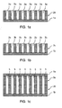
- Gerhard et al. (2007 Annual Report on Electrical Insulation and Dielectric Phenomena, pages 453-456 ) describes a three-layer ferroelectret in which a polytetrafluoroethylene film provided with a plurality of uniform continuous recesses by mechanical or laser-based drilling is sandwiched between two uniform fluoroethylene propylene films.
- a polytetrafluoroethylene film provided with a plurality of uniform continuous recesses by mechanical or laser-based drilling is sandwiched between two uniform fluoroethylene propylene films.
- the introduction of continuous recesses by mechanical or laser-based drilling is expensive and unsuitable for the production of large quantities.
- electromechanical transducers can advantageously be produced in large numbers.
- the recesses can be formed by the erfmdungswashe method in many different forms.
- the shape of the recess is therefore not limited to a cylindrical shape having a circular cross-sectional area.
- the inventive method offers the possibility to combine formed in different shapes recesses. In this way, on the one hand advantageously, the total void volume of the resulting cavities can be maximized.
- the electromechanical, in particular piezoelectric, properties of the electromechanical transducers produced by the method according to the invention can be adapted by selecting the recess shape, arrangement and / or distribution.
- burrs and other sharp-edged recessed surface irregularities can be avoided, which could advantageously affect the electromechanical, in particular piezoelectric, properties.
- the recessed polymer layer may advantageously soften the electromechanical transducer to be made along its thickness to decrease its modulus of elasticity, allow a poling process in the resulting cavities, and / or separate charge layers formed in the continuous polymer layers after the charging process.
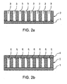
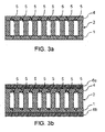
- the cover comprises a second recesses-containing polymer layer and a second continuous polymer layer, wherein the second recesses polymer layer is disposed on the second continuous polymer layer.
- the cover may consist of a second recesses-comprising polymer layer and a second continuous polymer layer.
- the cover is a third continuous polymer layer.
- the cover is produced by applying a polymer layer comprising second recesses to a second continuous polymer layer by means of a printing and / or coating method.
- the polymer layer comprising the first recesses is joined to the cover by a lamination process, in particular under elevated pressure and / or at an elevated temperature and / or under irradiation with ultraviolet light and / or under irradiation with infrared light.
- laminating under elevated pressure and / or at an elevated temperature may occur between two hot rotating cylinders.
- the pressure and / or the temperature are preferably selected such that the polymer layers connect, whereby the shape of the recesses is maintained.
- the polymer layer comprising the first recesses and / or the first continuous polymer layer and / or the polymer layer comprising the second recesses and / or the second continuous polymer layer can be heated.
- the material of the polymer layer comprising the first recesses and / or the polymer layer comprising the second recesses can be solidified, in particular completely, for example completely dried and / or completely crosslinked and / or completely solidified and / or completely crystallized.
- the material of the first recesses comprising polymer layer may be partially solidified after application to the first continuous polymer layer, for example, partially dried and / or partially crosslinked and / or partially solidified and / or partially crystallized.
- the material of the second recesses comprising polymer layer may be partially solidified after application to the second continuous polymer layer, for example, partially dried and / or partially crosslinked and / or partially solidified and / or partially crystallized.
- the material of the first recesses-comprising polymer layer can be partially solidified after application to the second continuous polymer layer, for example partially dried and / or partially crosslinked and / or partially solidified and / or partially crystallized, that its viscosity is increased compared with the viscosity when applied to the continuous polymer layer.
- the dimensional stability of the recesses can be improved.
- only partial solidification offers the possibility of the first recesses comprising polymer layer with the third continuous one Polymer layer or the second recesses comprising polymer layer to connect by further, in particular complete, solidification of the material.
- connecting the first recesses-comprising polymer layer to the cover takes place by only partially solidifying the material of the first recesses-comprising polymer layer after application to the first continuous polymer layer, and / or only partially solidifying the material of the second recesses Polymer layer after application to the second continuous polymer layer, and further, in particular complete, solidifying the material of the first recesses comprehensive polymer layer after the application of the cover, and / or further, in particular complete, solidifying the material of the second recesses comprising polymer layer after the application of the Cover.
- solidification, drying and / or crosslinking and / or solidification and / or crystallization can be understood.
- the material of the first recesses-comprising polymer layer after application to the first continuous polymer layer and / or the material of the second recesses comprising polymer layer after application to the second continuous polymer layer, for example thermally, and only after application to network the cover.
- a further example is to use an amorphously solidifying and / or crystallizing material, in particular polymer, for example a polyurethane, for the polymer layer comprising the first recesses and / or the polymer layer comprising the second recesses.
- the amorphous solidifying and / or crystallizing material can be applied to the first or second continuous polymer layer, for example, as a dispersion comprising the formation of the first or second recesses.
- the amorphous solidifying and / or crystallizing material for example after application to the first or second continuous polymer layer solidify partially amorphous and / or crystallize and solidify completely amorphous after application of the cover and / or crystallize and thereby the first recesses comprehensive polymer layer with the Connect the cover.
- the amorphous solidifying and / or crystallizing material may also solidify completely amorphous and / or crystallize after application to the first and second continuous polymer layer and be crosslinked after application of the cover, wherein the first recesses polymer layer is connected to the cover.
- the amorphous solidifying and / or crystallizing material can solidify completely amorphous after application to the first and second continuous polymer layer and / or crystallize and after applying the cover to a Temperature be heated at which the amorphous solidifying and / or crystallizing material softens and / or melts, wherein the third continuous polymer layer or the other recesses comprehensive polymer layer is wetted, wherein the structure of the recesses comprising polymer layer is maintained and wherein after cooling to a lower temperature the first recesses comprising polymer layer is connected to the cover.
- the polymer layer comprising the material of the first and / or second recesses can be crosslinked, for example thermally, by irradiation with ultraviolet light, by irradiation with infrared light and / or by drying.
- crosslinking may be thermal, by irradiation with infrared light, or by drying.
- the application of the first recesses comprising polymer layer and / or applying the second recesses polymer layer by doctoring, spin coating (dipcoating), spray coating (spray coating), curtain coating (curtain coating), coating by means of nozzle application (Slot dye coating), flexographic printing, gravure printing, pad printing, digital printing, thermal transfer printing, through-printing, in particular high-pressure, planographic printing, gravure printing (offset printing) and / or screen printing, and / or a roller application method, for example with hot melt roller applicators from the company Hardo Maschinenbau GmbH (Bad Salzuflen, Germany).
- the polymer layer comprising the first recesses and / or the polymer layer comprising the second recesses can be applied, for example, by doctoring, spincoating, dipcoating, spraycoating and / or curtaincoating in combination with matrices or stencils ,
- the polymer layer comprising the first recesses and / or the polymer layer comprising the second recesses are applied by a screen printing method.
- the application of the polymer layer comprising the first recesses and / or the polymer layer comprising the second recesses can be effected with a, for example electrically, heated screen, in particular screen printing fabric.
- Heated sieves for screen printing are offered, for example, by Koenen GmbH (Ottobrunn, Germany) under the trade name Hot Screen.
- thermoplastic substances such as reactive and non-reactive hotmelt adhesives based on polyurethane, polyester and / or polyamide, especially hot-melt pastes, or screen printing pastes, which include high-boiling solvents and / or drying under ultraviolet light, as Screen printing pastes are used.
- thermoplastic substances or hot-melt pastes are preferably solid at room temperature and reach at the temperatures to which the wire is heated, for example ⁇ 60 ° C to ⁇ 80 ° C, a viscosity which is comparable to that of conventional screen-printing pastes, for example from ⁇ 1000 mPa ⁇ s to ⁇ 20000 mPa ⁇ s.
- the addition of solvents is not required in such hot-melt pastes.
- the thermoplastic substances cool on contact with the continuous polymer layer and can thus remain contour sharp.
- the use of a heated screen and a thermoplastic substance has the advantage that can be dispensed with a drying process.
- Screen printing pastes which comprise high-boiling solvents and / or are drying under ultraviolet light can be applied when using a heated screen, in particular screen-printed fabric, and optionally a heated doctor blade.
- a heated screen By heating the screen, the viscosity of the paste is lowered.
- the paste cools and its viscosity increases. This has the advantage that the contour sharpness can be increased.
- low-viscosity pastes may optionally also be used.
- the fineness of the fabric is the number of threads per centimeter understood. For example, screen printed fabrics having a filament count of at least 120 threads per centimeter, especially at least 150 threads per centimeter, can be used.
- the pressure and / or flood doctor blades can be heated.
- the material of the first or second recesses comprising polymer layer can be partially or completely solidified, for example, dried and / or crosslinked and / or solidified and / or crystallized. If necessary, the prints can be done wet to wet. While the structure of the recesses-comprising polymer layer can be applied directly by a printing process, the positions of the later recesses in the coating process described above are initially masked or masked.
- the application of the first recesses-comprising polymer layer and / or the application of the second recesses polymer layer by transfer coating.
- transfer coating is understood to mean, in particular, that the polymer layer comprising recesses is first formed on a transfer layer, for example a release paper or release film, by a printing and / or coating process and then transferred to the continuous polymer layer and bonded to the continuous polymer layer becomes.
- Suitable printing and / or coating methods are the abovementioned printing and / or coating methods.
- the transfer coating advantageously offers the possibility of spatially and temporally separating the production of the first and / or second recesses comprising polymer layer and the joining of the recesses comprehensive layer / s with the continuous layers.
- the recesses of the polymer layer comprising first recesses are formed continuously by the polymer layer comprising first recesses, in particular in the direction of the continuous polymer layers, and / or the recesses of the polymer layer comprising second recesses are continuous through the polymer layer comprising the second recesses, in particular in the direction of the continuous polymer layers.
- the cavities formed after completion of the process according to the invention contact one (first) continuous polymer layer on one side and the other (second or third) continuous poly-layer on the other side. This in turn has an advantageous effect on the electromechanical behavior of the produced electromechanical energy converter.
- the polymer layer comprising the first and / or second recesses can be produced both by printing and / or coating the first or second continuous polymer layer with a coherent recesses-containing polymer layer and by printing and / or coating the first or second continuous polymer layer with the same or different, isolated or interconnected structures, for example structures with a rather small area, such as points and lines, such as curved or straight, single or crossed lines or perimeter lines of geometric figures, such as a circle or a perimeter of a cross, or structures with a larger area, such as filled rectangles, circles, crosses, et cetera, be trained.
- structures with a rather small area such as points and lines, such as curved or straight, single or crossed lines or perimeter lines of geometric figures, such as a circle or a perimeter of a cross, or structures with a larger area, such as filled rectangles, circles, crosses, et cetera, be trained.
- the size and layer thickness of the structures is preferably set such that the continuous polymer layers can not touch and / or that the total void volume resulting after completion is as large as possible.
- the polymer layer comprising the first and / or second recesses can have, for example, in each case a layer thickness of ⁇ 1 ⁇ m to ⁇ 800 ⁇ m, in particular of ⁇ 10 ⁇ m to ⁇ 400 ⁇ m.
- the first recesses comprehensive polymer layer in the finished electromechanical transducer in particular a layer thickness of ⁇ 1 microns to ⁇ 800 microns, for example from ⁇ 10 microns to ⁇ 400 microns, exhibit.
- both a first and a second recesses comprehensive polymer layer are applied, so in the finished electromechanical transducer, the common layer thickness of the first recesses comprehensive polymer layer and the second recesses comprehensive polymer layer ⁇ 1 microns to ⁇ 800 microns, for example from ⁇ 10 ⁇ m to ⁇ 400 ⁇ m.
- the layer thickness of the first and / or second recesses may comprise, for example, the use of solvent-containing printing inks, inks, pastes, formulations, paints or adhesives directly after applying the recesses polymer layer to the continuous layer be greater or even significantly greater than the layer thickness of the resulting recesses comprehensive polymer layer in the finished electromechanical transducer.
- the layout, the printing process parameters and / or the coating process parameters are preferably set such that the polymer layers comprising the recesses have no cavities, in particular gas inclusions, which are not in contact with the continuous polymer layers.
- the recesses of the polymer layer comprising the first recesses and the recesses of the polymer layer comprising the second recesses may be formed and arranged such that at least part of the recesses of the first recesses comprising the polymer layer and a portion of the recesses of the second recesses comprising the polymer layer are partially or completely applied when the cover is applied overlap.
- the recesses of the polymer layer comprising the first recesses and the recesses of the polymer layer comprising second recesses are formed and arranged in such a way that, when the cover is applied, a recess of the first recesses comprising polymer layer and a recess of the second recesses comprising polymer layer partially or completely overlap.
- the recesses of the first recesses comprehensive polymer layer and the recesses of the second recesses comprising polymer layer are preferably formed and arranged so that each cover a recess of the first recesses comprehensive polymer layer and a recess of the second recesses comprising polymer layer form a common cavity during application of the cover ,
- the recesses of the polymer layer comprising the first recesses and the recesses of the polymer layer comprising the second recesses are preferably designed and arranged so that a respective recess of the first recesses comprising the polymer layer and a recess of the second recesses completely overlap the polymer layer.
- the polymer layer comprising the first and second recesses may be designed congruently, in particular identically. In this way, cavities can be realized which are continuous from the continuous polymer layer on one side to the continuous polymer layer on the other side.
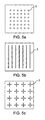
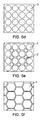
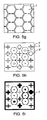
- At least a part of the recesses of the polymer layer comprising the first recesses and / or the recesses of the polymer layer comprising second recesses may be formed into shapes having a cross-sectional area selected from the group consisting of substantially round, for example circular, elliptical or oval, polygons, for example triangular, rectangular, trapezoidal, diamond-shaped, pentagonal, hexagonal, in particular honeycomb-shaped, cruciform, star-shaped and partially round and partially polygonal, for example S-shaped, cross-sectional surfaces have.
- the recesses of the first recesses-comprising polymer layer and / or the recesses of the polymer layer comprising second recesses may also be completely formed in shapes having a cross-sectional area selected from the group consisting of substantially round, for example circular, elliptical or oval, polygons, for example, triangular, rectangular, trapezoidal, diamond-shaped, pentagonal, hexagonal, in particular honeycomb-shaped, cross-shaped, star-shaped and partially round and partially polygonal, for example S-shaped, cross-sectional surfaces have, as well as be completely formed in deviating forms.
- the recesses of the polymer layer comprising the first recesses and / or the recesses of the polymer layer comprising the second recesses are honeycomb-shaped and / or arranged.
- a honeycomb design and arrangement of the recesses on the one hand has a very large total void volume result.
- a honeycomb design and arrangement of the recesses can have a high mechanical stability.
- the size of the cross-sectional areas may be the same or different for all recesses of a recesses-comprising polymer layer.
- the recesses in the polymer layer comprising the first and / or second recesses may be formed both homogeneously and heterogeneously distributed.
- the recesses in the first and / or second recesses comprising polymer layer may be formed homogeneously distributed.
- the recesses in the first and / or second recesses comprising polymer layer may optionally be partially or completely interconnected.
- the polymer layer comprising first recesses and / or the polymer layer comprising the second recesses comprises recesses formed in different shapes.
- the polymer layer comprising first and / or second recesses may have a multiplicity of recesses formed in a first shape and a multiplicity of recesses formed in a second shape and optionally a multiplicity of recesses, et cetera, formed in a third shape.
- the recesses formed in different shapes in the first or second recesses comprising polymer layer can be homogeneously or heterogeneously distributed and / or formed partially or completely connected to each other.
- the electromechanical, in particular piezoelectric, properties of the electromechanical transducers produced by the method according to the invention can be adapted by selecting the recess shape, arrangement and / or distribution.
- the recesses of the first and / or second recesses comprising layer may be formed in forms which have no circular, in particular no substantially circular, cross-sectional area. This is because the total void volume of layers having only cavities with circular or substantially circular cross-sectional areas is less than the total void volume, for example, in a homogeneously distributed array of cavities with circular and diamond-shaped cross-sectional areas or one exclusively on cavities with honeycomb cross-sectional areas based arrangement.
- the polymer layer comprising first and second recesses may, in principle, be formed independently of each other from any polymer which is suitable for enabling a poling process in the cavities and for separating the charge layers formed in the polymer films after the charging process.
- the recesses comprising polymer layers may be formed of an elastomer.
- a printing ink, an ink, a paste, a formulation, a paint or an adhesive can be used. These can be formulated both directly before processing and commercially available.
- the printing ink, the ink, the paste, the formulation, the paint or the adhesive or the first and / or second recesses comprising polymer layer at least one polymer selected from the group consisting of cellulose esters, cellulose ethers, rubber derivatives, polyester resins, unsaturated polyesters, alkyd resins , Phenolic resins, amino resins, amido resins, ketone resins, xylene-formaldehyde resins, epoxy resins, phenoxy resins, polyolefins, polyvinyl chloride, polyvinyl esters, polyvinyl alcohols, polyvinyl acetals, polyvinyl ethers, polyacrylates, polymethacrylates, polystyrenes, polycarbonates, polyesters, copolyesters, polyamides, silicone resins, polyurethanes, especially polyurethanes, and Mixtures of these polymers, in particular as binders, comprise or be formed therefrom.
- cellulose esters cellulose ether
- the ink, the ink, the paste, the formulation, the paint or the adhesive or the first and / or second recesses polymer layer comprises a resin
- the printing ink, the ink, the paste, the formulation, the paint or the adhesive or the polymer layer comprising the first and / or second recesses optionally further comprises one or more resin hardeners.
- the ink, the paste, the formulation, the paint or the adhesive or the first and / or second recesses polymer layer comprising a variety of commercially available products, in particular as a binder, suitable, for example, under the trade name Noriphan HTR, Noriphan PCI, Noriphan N2K, Noricryl and NoriPET from Pröll KG, Weissenburg in Bavaria, Germany, or under the trade name Maraflex FX from Marabu GmbH & Co.
- Urethane acrylates can be used as solutions in reactive diluents (low-viscosity methacrylates or acrylic esters), as low-viscosity oligomers, as solids for powder coating technology or as urethane acrylate dipserions. Urethane acrylates are available, for example, under the trade / trademark Desmolux from Bayer MaterialScience AG (Leverkusen, Germany). For curing, for example, electron beam curing, mono-cure technology and dual-cure technology are suitable. Isocyanatourethanacryle are particularly suitable for dual cure technology.
- the printing ink, the ink, the paste, the formulation, the paint or the adhesive may be water-based or based on solvents other than water.
- the polymer layer comprising the printing ink, the ink, the paste, the formulation, the lacquer or the adhesive or the first and / or second recesses may comprise or be formed from one or more polyurethanes.
- the polymer layer comprising the printing ink, the ink, the paste, the formulation, the paint or the adhesive or the first and / or second recesses may comprise one or more one-component polyurethanes and / or one or more two-component polyurethanes and / or one or more aqueous polyurethane dispersions and / or comprise one or more polyurethane hot melt adhesives or be formed therefrom.
- the printing ink, the ink, the paste, the formulation, the lacquer or the adhesive or the first and / or second recesses comprising polymer layer may comprise or be formed from one or more one-component polyurethanes, which prepolymers prepared by reaction of alcohols with a stoichiometric excess of polyfunctional isocyanates having an average functionality greater than 2 and up to 4.
- these prepolymers may further comprise additives and / or solvents.
- the prepolymers can be obtained, for example, by reacting polyisocyanates with alcohols which are mixtures of polyols with on average monofunctional alcohols to form urethane groups and terminal isocyanate groups.
- polyols it is possible to use the polyols known to one skilled in the art, such as, for example, polyether, polyacrylate, polycarbonate, polycaprolactone, polyurethane and polyester polyols, such as are known in polyurethane chemistry Ullmann's Encyclopedia of Industrial Chemistry, 4th Edition, Volume 19, pp. 304-5, Verlag Chemie, Weinheim , or in polyurethane paints, adhesives and sealants by Ulrich Meier-Westhues, Vincentz Network, Hannover, 2007, are described.
- the polyols designated Desmophen® from Bayer MaterialScience AG, Leverkusen, Germany can be used.
- polyfunctional isocyanates having an average functionality> 2 the usual in polyurethane chemistry, known in the art products can be used, as for example in Ullmann's Encyclopedia of Industrial Chemistry, 4th Edition, Volume 19, pp. 303-4, Verlag Chemie, Weinheim , are described. Examples which may be mentioned are biuret trimerized isocyanates, such as trimerized hexamethylene diisocyanate Desmodur® N (trade name of Bayer MaterialScience AG, Leverkusen, Germany), or mixtures thereof with diisocyanates or isocyanurate trimerized isocyanates or their mixtures with diisocyanates. Also, the adducts of diisocyanates to polyols, for example of tolylene diisocyanate to trimethylolpropane are suitable.
- the prepolymers may contain additives such as catalysts for accelerating the curing, for example tertiary amines such Dimorpholinodiethylether, bis [2-N, N- (dimethylamino) ethyl] ether or tin compounds such as dibutyltin dilaurate or stannous octoate, aging and light stabilizers, drying agents Stabilizers, for example benzoyl chloride, adhesion promoters to improve the adhesion, plasticizers, such as dioctyl phthalate, as well as pigments and fillers may be added.
- additives such as catalysts for accelerating the curing, for example tertiary amines such Dimorpholinodiethylether, bis [2-N, N- (dimethylamino) ethyl] ether or tin compounds such as dibutyltin dilaurate or stannous octoate, aging and light stabilizers, drying agents
- the prepolymers can be prepared by reacting the mixture of polyols and monofunctional alcohol with a stoichiometric excess of di- or polyfunctional isocyanate compound. However, it is also possible to react the monofunctional hydroxyl compound in an upstream reaction with the isocyanate compound.
- the polymer layer comprising the printing ink, the ink, the paste, the formulation, the lacquer or the adhesive or the first and / or second recesses may also comprise or be formed from one or more two-component polyurethanes comprising, for example, a component with isocyanate groups and a isocyanate-reactive component.
- the polymer layer comprising suitable polyisocyanates for the printing ink, the ink, the paste, the formulation, the paint or the adhesive or the first and / or second recesses may be the NCO-functional compounds known to the person skilled in the art having a functionality of preferably 2 or more Find.
- di- or triisocyanates examples include tetramethylene diisocyanate, cyclohexane-1,3- and 1,4-diisocyanate, hexamethylene diisocyanate (HDI), 1-isocyanato-3,3,5-trimethyl-5-isocyanatomethyl-cyclohexane (isophorone diisocyanate, IPDI) , Methylene bis (4-isocyanatocyclohexane), tetramethylxylylene diisocyanate (TMXDI), triisocyanatononane, tolylene diisocyanate (TDI), diphenylmethane-2,4'-and / or -4,4'-and / or -2,2'-diisocyanate ( MDI), triphenylmethane-4,4'-diisocyanate, naphthylene-1,5-diisocyanate, 4-isocyanatomethyl-1,8-oct
- the printing ink, the ink, the paste, the formulation, the paint or the adhesive or the first and / or second recesses comprehensive Polymer layer the higher molecular weight compounds with isocyanurate, urethane, allophanate, biuret, Iminooxadiazintrion-, Oxadiazintrion- and / or uretdione groups based on aliphatic and / or cycloaliphatic and / or aromatic diisocyanates used.
- the printing ink, the ink, the paste, the formulation, the paint or the adhesive or the first and / or second recesses comprising polymer layer compounds with biuret, iminooxadiazinedione, - isocyanurate and / or uretdione groups based on hexamethylene diisocyanate, Isophorone diisocyanate, 4,4'-diisocyanatodicyclohexylmethane, diphenylmethane-4,4'-diisocyanate, diphenylmethane-2,4'-diisocyanate, 2,4-tolylene diisocyanate, 2,6-tolylene diisocyanate and / or xylylene diisocyanate used.
- the preparation and / or use of the isocyanate-containing component can be carried out in a solvent, examples being N-methylpyrrolidone, N-ethylpyrrolidone, xylene, solvent naphtha, toluene, butyl acetate, methoxypropyl acetate, acetone or methyl ethyl ketone. It is possible to add solvent after the reaction of the isocyanate groups. It is also possible to use protic solvents, such as alcohols, which serve, for example, to stabilize the solution or to improve paint properties. Any mixtures of solvents are also possible.
- the amount of solvent is generally such that from 20 weight percent to ⁇ 100 weight percent, preferably 50 weight percent to 90 weight percent solutions result.
- Suitable catalysts are described in "Polyurethane Chemistry and Technology", Volume XVI, Part 1, Section IV, pages 129-211 , The Kinetics and Catalysis of the Isocyanate Reactions.
- tertiary amines, tin, zinc or bismuth compounds, or basic salts are suitable. Preference is given to dibutyltin dilaurate and octoate.
- Suitable isocyanate-reactive components such as, for example, polyhydroxyl compounds are known per se to the person skilled in the art. These are preferably the known binders based on polyhydroxy polyesters, polyhydroxy polyurethanes, polyhydroxy polyethers, polycarbonate diols or polymers containing hydroxyl groups, such as the known polyhydroxy polyacrylates, polyacrylate polyurethanes and / or polyurethane polyacrylates. Examples which may be mentioned are the Desmophen® polyols from Bayer MaterialScience AG, Leverkusen, Germany.
- the polymer layer comprising the printing ink, the ink, the paste, the formulation, the lacquer or the adhesive or the first and / or second recesses may be also comprise one or more aqueous polyurethane dispersions, for example a polyurethane-polyurea dispersion, or be formed from such.
- aqueous polyurethane dispersions for formulating the printing ink, the ink, the paste, the formulation, the lacquer or the adhesive are, for example, those described in US Pat US 2,479,310 A . US 4,092,286 A . DE 2 811 148 A . DE 3603996 and EP 08019884 are described.
- Suitable diol and / or polyol components for the preparation of the polyurethane-polyurea dispersions are compounds having at least two isocyanate-reactive hydrogen atoms and an average molecular weight of ⁇ 62 to ⁇ 18000, preferably ⁇ 62 to ⁇ 4000 g / mol.
- suitable structural components are polyethers, polyesters, polycarbonate, polylactones and polyamides.
- Preferred polyols have ⁇ 2 to ⁇ 4 preferably ⁇ 2 to ⁇ 3 hydroxyl groups. Mixtures of such compounds are also possible.
- the polyurethane-polyurea dispersion can be used both alone and in combination with one or more hydrophilically modified crosslinkers.
- the additional crosslinking of the polyurethane-polyurea polymer causes a significant increase in the heat resistance and the hydrolysis resistance of the adhesive bond.
- Latent-reactive polyurethane-polyurea dispersions can also be used.
- Latent-reactive polyurethane-polyurea dispersions are for example in EP 0 922 720 A and WO 2008/071307 described.
- the advantage of this product class lies in the fact that the crosslinking reaction of the polymer is triggered during the laminating process which involves the heating of the recesses, which is in any case necessary for heating the recesses.
- the dispersion can be used alone or with the binders, auxiliaries and / or impact substances known in coating and adhesive technology, in particular emulsifiers and light stabilizers, such as UV absorbers and hindered amines (HALS), antioxidants, fillers, anti-settling agents, defoaming agents, wetting agents, leveling agents , Reactive diluents, plasticizers, neutralizing agents, catalysts, auxiliary solvents and / or thickeners and / or additives, such as pigments, dyes or matting agents. Also tackifiers (“tackifiers”) can be added.
- the additives can be added immediately before processing. However, it is also possible to add at least part of the additives before or during the dispersion of the binder.
- the rheology of the aqueous polyurethane dispersions is preferably adjusted with suitable thickeners so that they no longer run after application, for example to the continuous polymer layer.
- the intrinsic viscosity of the flow limit can be high.
- the use of such an aqueous polyurethane dispersion has the advantage that the recesses comprehensive polymer layer can be dried after application first, wherein the polyurethane polymer - depending on the polymer or polymer mixture used - amorphous solidifies and / or crystallized and the recesses comprehensive polymer layer in a subsequent Lamination process can be heated just to the extent that the polyurethane polymer softens and / or melts and the continuous polymer layer is wetted, wherein the structure of the recesses comprehensive polymer layer is maintained.
- the polymer layer comprising the ink, the ink, the paste, the formulation, the lacquer or the adhesive or the first and / or second recesses may also comprise or be formed from a reactive or non-reactive polyurethane hotmelt adhesive.
- Suitable reactive polyurethane hot melt adhesives are, for example, in DE 3827724 . DE 4114229 and EP 354527 described. These hot-melt adhesives have free isocyanate groups, which crosslink after application with moisture from the substrate and thus achieve the required heat resistance.
- the polyurethane hotmelt adhesives can, alone or with the binders, auxiliaries and / or impact substances known in coating and adhesive technology, in particular light stabilizers, such as UV absorbers and sterically hindered amines (HALS), furthermore contain antioxidants, fillers, wetting agents, flow control agents, reactive agents. Thinners, plasticizers, neutralizing agents, catalysts, auxiliary solvents, tackifying resins (tackifiers) and / or additives, such as pigments, dyes or matting agents are used.
- the additives can be added immediately before processing. However, it is also possible to add at least part of the additives before or during the preparation of the reactive hotmelt adhesive.
- Suitable non-reactive polyurethane hot melt adhesives are, for example, in DE 1256822 . DE 1930336 or EP 192946 described.
- Other suitable non-reactive hot melt adhesives are polyesters and copolyesters, polyamide, polyolefins (APAO), ethylene vinyl acetate copolymers, polyester elastomers, polyurethane elastomers and copolyamide elastomers.
- the ink, the ink, the paste, the formulation, the paint or the adhesive or the first and / or second recesses comprising polymer layer further comprises at least one additive for improving the electret and / or electromechanical, such as piezoelectric properties.
- the additive can thereby improve any polymer properties as well as parameters which have an effect on the electromechanical, for example piezoelectric, properties of the material.
- the additive can improve the dielectric constant, the modulus of elasticity, the viscoelastic behavior, the maximum elongation and / or the dielectric strength of the polymer or of the polymer mixture.
- an additive which lowers the dielectric constant and / or the electrical conductivity and / or the modulus of elasticity of the polymer and / or increases the dielectric strength of the polymer.
- clay particles, fine ceramic powders and / or plasticizers such as hydrocarbon oils, mineral oils, silicone oils and / or silicone elastomers, in particular of high molecular weight, can be used as additives.
- the polymer layer comprising the printing ink, the ink, the paste, the formulation, the lacquer or the adhesive or the first and / or second recesses may comprise additives which simplify the application of the recesses-comprising polymer layer. These are, for example, flow control additives, defoamers and / or rheology additives as well as additives to improve the properties of the recesses comprising polymer layer, such as plasticizers.
- the printing ink, the ink, the paste, the formulation, the lacquer or the adhesive or the polymer layer comprising first and / or second recesses may also comprise solvents.
- solvents examples of these are ethyl acetate, butyl acetate, methoxypropyl acetate, ethoxypropyl acetate, acetone, cyclohexanone, toluene, xylene, Solvesso 100, Shellsol A and / or mixtures of two or more of these solvents.
- the first and / or second and / or third continuous polymer layers are preferably compact polymer layers.
- the term "compact" in the sense of the present invention means that the continuous polymer layers have as few, in particular no, inclusions as gas bubbles.
- the continuous polymer layers may be polymer films.
- the first and / or second and / or third continuous polymer layer can in principle be prepared independently of one another by all known processes for the production of, in particular thin, layers and films.
- the first and / or second and / or third continuous polymer layer can be prepared independently of each other via extrusion, doctor blading, in particular solution doctor blades, spin coating, in particular spin coating, or spraying.
- commercially available continuous polymer layers or polymer films can also be used as the first and / or second and / or third continuous polymer layer.
- the first and / or second and / or third continuous polymer layer can, independently of one another, basically be formed from any polymer or polymer mixture which is suitable for holding charge for a long period of time, for example a few months or years.
- the first and / or second and / or third continuous polymer layers may comprise or consist of almost any, identical or different polymer materials.
- the first and / or second and / or third continuous polymer layer may comprise at least one polymer selected from the group consisting of polycarbonates, perfluorinated or partially fluorinated polymers and co-polymers such as polytetrafluoroethylene (PTFE), fluorinated ethylene propylene (FEP), perfluoroalkoxyethylenes (PFA).
- PTFE polytetrafluoroethylene
- FEP fluorinated ethylene propylene
- PFA perfluoroalkoxyethylenes
- Polyesters such as polyethylene terephthalate (PET) or polyethylene naphthalate (PEN), polyimides, especially polyetherimide, polyethers, polymethyl methacrylates, cyclo-olefin polymers, cyclo-olefin copolymers, polyolefins such as polypropylene, and blends of these polymers include or may be formed therefrom.
- Such polymers may advantageously retain the introduced polarization for a long time.
- Suitable polycarbonates are obtainable, for example, by reaction of carbonic acid derivatives, such as diphenyl carbonate, dimethyl carbonate or phosgene, with polyols, preferably diols.
- diols examples include ethylene glycol, 1,2-propanediol, 1,3-propanediol, 1,3-butanediol, 1,4-butanediol, 1,6-hexanediol, 1,8-octanediol, neopentyl glycol, 1,4- Bishydroxyrnethylcyclohexane, 2-methyl-1,3-propanediol, 2,2,4-trimethylpentanediol-1,3, dipropylene glycol, polypropylene glycols, dibutylene glycol, polybutylene glycols, bisphenol A, bisphenol F, trimethylcyclohexyl-bisphenol (bisphenol-TMC), mixtures from these and lactone-modified diols.
- ethylene glycol 1,2-propanediol, 1,3-propanediol, 1,3-butanediol, 1,4-butanedi
- polycarbonates prepared bisphenol A, bisphenol F, Trimethylcyclohexyl-bisphenol (bisphenol-TMC) and mixtures thereof and most preferred are polycarbonates based on bisphenol A.
- the continuous polymer layers may independently comprise or be formed from a homopolymer.
- the first and / or second and / or third continuous polymer layer may comprise at least one additive for improving the electret and / or electromechanical, for example piezoelectric, properties.
- the additive can thereby improve any polymer properties as well as parameters which have an effect on the electromechanical, for example piezoelectric, properties of the material.
- the additive can improve the electret properties, the dielectric constant, the modulus of elasticity, the viscoelastic behavior, the maximum elongation and / or the dielectric breakdown strength of the polymer or of the polymer mixture.
- one or more additives are used which improve the electret properties, that is, which increase the charge storage ability, decrease the electrical conductivity and / or increase the dielectric strength of the polymer.
- clay particles, fine ceramic powders and / or plasticizers such as hydrocarbon oils, mineral oils, silicone oils and / or silicone elastomers, in particular of high molecular weight, can be used as additives.
- hydrocarbon oils, mineral oils, silicone oils and / or silicone elastomers in particular of high molecular weight
- the first and / or second and / or third continuous polymer layer can independently of one another have, for example, a layer thickness of ⁇ 10 ⁇ m to ⁇ 500 ⁇ m, for example from ⁇ 20 ⁇ m to ⁇ 250 ⁇ m ,
- the transducer according to the invention may have one or more further continuous polymer layers.
- Such a further, continuous polymer layer can, for example, be arranged on the side of the first and / or second and / or third continuous polymer layer, which lies opposite the polymer layer comprising the adjacent recesses.
- the continuous polymer layers can be tempered before use in the process according to the invention or within the scope of the process according to the invention.
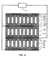
- the method may further comprise the method step D) of applying an electrode to the first continuous polymer layer and an electrode to the cover, in particular to the continuous polymer layer (second or third) of the cover.
- the electrodes can also already be provided together with the first and / or second and / or third continuous polymer layer, in particular each formed thereon.
- the electrodes can be applied by methods known to those skilled in the art. For this purpose, for example, methods such as sputtering, vapor deposition, chemical vapor deposition (CVD), printing, knife coating, spin coating in question.
- the electrodes can also be glued in prefabricated form.
- the electrode materials may be conductive materials known to those skilled in the art.
- metals, metal alloys, semiconductors, conductive oligo- or polymers such as polythiophenes, polyanilines, polypyrroles, conductive oxides or mixed oxides, such as indium tin oxide (ITO), or polymers filled with conductive fillers come into question.
- Suitable fillers for polymers filled with conductive fillers are, for example, metals, conductive carbon-based materials, for example carbon black, carbon nanotubes (CNTs), or conductive oligo- or polymers.
- the filler content of the polymers is preferably above the percolation threshold, which is characterized in that the conductive fillers form continuous electrically conductive paths.
- the electrodes may also be structured in the context of the present invention.
- the electrodes may be structured such that the transducer has active and passive regions.
- the electrodes can be structured in such a way that, in particular in the sensor mode, the signals are detected spatially resolved and / or, in particular in the actuator mode, the active regions can be specifically controlled. This can be achieved, for example, by providing the active regions with electrodes, whereas the passive regions have no electrodes.
- the method may further comprise the method step E): charging the arrangement resulting from method step C), in particular a sandwich arrangement.
- the first continuous polymer layer and the cover, in particular the continuous polymer layer (second or third) of the cover can be charged with charges of different sign.
- the charging can be done for example by tribocharging, electron beam bombardment, applying an electrical voltage to the electrodes or corona discharge.
- the charging by a two-electrode corona arrangement respectively.
- the needle voltage may be at least ⁇ 20 kV, for example at least ⁇ 25 kV, in particular at least ⁇ 30 kV.
- the charging time can be at least ⁇ 20 s, for example at least ⁇ 30 s, in particular at least ⁇ 1 min.
- both process step D) and then process step E) and also process step E) and then process step D) can be carried out.
- the method may further comprise the method step F): Stacking of two or more arrangements resulting from method step C), in particular a sandwich arrangement.
- the first continuous polymer layer and the cover, in particular the continuous layer (two or three) of the cover can each be contacted with an electrode.
- two adjacent, continuous polymer layers of different arrangements resulting from method step C) are charged with the same polarization.
- two adjacent, continuous polymer layers of different arrangements emerging from method step C) can contact the same electrode or be contacted with the same electrode.
- Another object of the present invention is an electromechanical, for example, piezoelectric transducer, in particular produced by a method according to the invention comprising a first continuous polymer layer, a polymer layer comprising first recesses and a cover, wherein the first recesses polymer layer between the first continuous polymer layer and the cover is arranged, wherein the recesses of the first recesses polymer layer are closed on one side by the first continuous polymer layer and on the other side through the cover to form cavities.
- the surfaces defining the recesses may be different than the recessed surfaces of drilling-made recesses.
- the surfaces bounding the recesses resulting from the process of the present invention could have less burrs and other sharp-edged surface irregularities that are not characteristic but could still have one, in particular negative, effect on the electromechanical, in particular piezoelectric, properties.
- the cover comprises a second recesses-containing polymer layer and a second continuous polymer layer, wherein the second continuous polymer layer on the second recesses comprising polymer layer and the second recesses comprising polymer layer, in particular to form common cavities on the first recesses Polymer layer is arranged.
- the cover is a third continuous polymer layer.
- the first recesses-comprising polymer layer comprises recesses formed in different shapes and / or recesses comprising the second recesses comprising polymer layer formed in different shapes.
- the recesses of the polymer layer comprising the first recesses and / or the polymer layer comprising the recesses of the second recesses may optionally be formed partially or completely connected to one another.
- At least a portion of the recesses of the first recesses-comprising polymer layer is formed in shapes that have no circular, in particular no substantially circular, cross-sectional area, and / or is at least a portion of the recesses of the second recesses polymer layer in forms formed, which have no circular, in particular no substantially circular, cross-sectional area.
- the total void volume can be increased by at least partially dispensing with recesses which have a circular, in particular a substantially circular, cross-sectional area.
- the polymer layer comprising the first and second recesses may in particular be congruent, in particular identical.
- the recesses may be formed homogeneously or heterogeneously distributed in the first and / or second recesses comprising polymer layer.
- the recesses in the first and / or second recesses comprising polymer layer may be formed homogeneously distributed.
- the recesses of the first recesses comprising the polymer layer are preferably formed continuously, in particular in the direction of the continuous polymer layers, by the polymer layer comprising the first recesses; and / or the recesses of the second recesses comprising polymer layer throughout, in particular in the direction of the continuous polymer layers, formed by the second recesses comprising polymer layer.
- the polymer layer comprising the first and / or second recesses may have a multiplicity of recesses formed in a first shape and a plurality of recesses formed in a second shape, and optionally a plurality of recesses formed in a third shape, et cetera.
- recesses in the first and / or second recesses comprising polymer layer may be homogeneously or heterogeneously distributed and / or partially or completely connected to each other.
- the recesses may be formed partially or completely in shapes having a cross-sectional area selected from the group consisting of substantially round, for example, circular, elliptical or oval, polygonal, for example, triangular, rectangular, trapezoidal, diamond-shaped, pentagonal , hexagonal, in particular honeycomb-shaped, cross-shaped, star-shaped and partially round and partially polygonal, for example S-shaped, cross-sectional surfaces have.
- the recesses of the first and / or second recesses layer have a honeycomb-shaped cross-sectional area or are honeycomb-shaped and / or arranged.
- a honeycomb formation and arrangement of the recesses on the one hand results in a very large total void volume.
- a honeycomb design and arrangement of the recesses can have a high mechanical stability.
- the size of the cross-sectional areas may be the same or different for all recesses of the recesses comprising polymer layer.
- the polymer layer comprising the first and / or second recesses may, for example, each have a layer thickness of ⁇ 1 ⁇ m to ⁇ 800 ⁇ m, in particular of ⁇ 10 ⁇ m to ⁇ 400 ⁇ m.
- the polymer layer comprising first recesses may have a layer thickness of ⁇ 1 ⁇ m to ⁇ 800 ⁇ m, for example of ⁇ 10 ⁇ m to ⁇ 400 ⁇ m.
- the electromechanical transducer has both a first and a second recesses-comprising polymer layer, the common layer thickness of the first recesses comprising polymer layer and the second recesses comprising polymer layer ⁇ 1 microns to ⁇ 800 microns, for example, from ⁇ 10 microns to ⁇ 400 microns, be.
- the first and / or second and / or third continuous polymer layer may, for example independently of one another, have, for example, a layer thickness of ⁇ 10 ⁇ m to ⁇ 500 ⁇ m, for example from ⁇ 20 ⁇ m to ⁇ 250 ⁇ m.
- the polymer layer comprising the first and / or second recesses may be, for example, at least one polymer selected from the group consisting of cellulose esters, cellulose ethers, rubber derivatives, polyester resins, unsaturated polyesters, alkyd resins, phenolic resins, amino resins, amido resins, ketone resins, xylene-formaldehyde resins, epoxy resins, phenoxy resins, polyolefms , Polyvinyl chloride, polyvinyl esters, polyvinyl alcohols, polyvinyl acetals, polyvinyl ethers, polyacrylates, polymethacrylates, polystyrenes, polycarbonates, polyesters, copolyesters, polyamides, silicone resins, polyurethanes, especially polyurethanes, and blends of these polymers.
- the polymer layer comprising first and / or second recesses may comprise or be formed from one or more one-component polyurethanes and / or one or more two-component polyurethanes and / or one or more polyurethane hotmelt adhesives.
- the first and / or second and / or third continuous polymer layer can be, for example, at least one polymer selected from the group consisting of polycarbonates, perfluorinated or partially fluorinated polymers and co-polymers, such as polytetrafluoroethylene (PTFE), fluorinated ethylene propylene (FEP), perfluoroalkoxyethylenes (PFA).
- PTFE polytetrafluoroethylene
- FEP fluorinated ethylene propylene
- PFA perfluoroalkoxyethylenes
- Polyesters such as polyethylene terephthalate (PET) or polyethylene naphthalate (PEN), polyimides, especially polyetherimide, polyethers, polymethyl methacrylates, cyclo-olefin polymers, cyclo-olefin copolymers, polyolefins such as polypropylene, and mixtures of these polymers include or be formed therefrom.
- PET polyethylene terephthalate
- PEN polyethylene naphthalate
- polyimides especially polyetherimide, polyethers, polymethyl methacrylates, cyclo-olefin polymers, cyclo-olefin copolymers, polyolefins such as polypropylene, and mixtures of these polymers include or be formed therefrom.
- an electromechanical transducer further comprises two electrodes, in particular electrode layers, one electrode contacting the first continuous polymer layer and the other electrode contacting the cover, in particular the continuous polymer layer (second or third) of the cover.
- the first continuous polymer layer and the cover, in particular the continuous polymer layer (second or third) of the cover can have an electrical charge with different signs.
- an electromechanical transducer may comprise two or more stacked arrangements, in particular a sandwich arrangement, each comprising a first continuous polymer layer, a polymer layer comprising first recesses and a cover, the polymer layer comprising the first recesses between the first continuous polymer layer and the first polymer layer Cover is arranged and wherein the recesses of the first recesses polymer layer are closed on one side by the first continuous polymer layer and on the other side through the cover to form cavities.
- the first continuous polymer layer and the cover in particular the continuous layer (two or three) of the cover, each contact an electrode.
- two adjacent, continuous polymer layers of different arrangements have the same charge polarization.
- two adjacent, continuous polymer layers of different arrangements can contact the same electrode.
- a transducer for example in the electromechanical and / or electro-acoustic field, in particular in the field of energy from mechanical vibrations (energy harvesting), the acoustics, ultrasound, medical diagnostics, acoustic microscopy, mechanical sensors, in particular pressure, force and / or strain sensors, robotics and / or communication technology, in particular in loudspeakers, vibration transducers, light deflectors, membranes, modulators for glass fiber optics, pyroelectric detectors, capacitors and control systems ,
- FIG. 1a shows a schematic cross section through a first continuous polymer layer 1a, on which a first recesses 3a comprehensive polymer layer 2a has been applied.
- FIG. 1b shows a schematic cross-section through a shape of a cover, which comprises a second recesses 3b comprising polymer layer 2b and a second continuous polymer layer 1b.
- Figure 1c shows a schematic cross section through the in the FIG. 1a Layer arrangement shown, to which the in FIG. 1b shown cover was applied.
- Figure 1c illustrates that the recesses 3a of the first recesses 3a comprising polymer layer 2a and the recesses 3b of the second recesses 3b comprising polymer layer 2b are formed and arranged such that after applying the cover 1b, 2b on the first recesses 3a comprising polymer layer 2a each have a recess 3a of the first recesses 3a comprising polymer layer 2a and a recess 3b of the second recesses 3b comprehensive polymer layer 2b overlap completely to form a common cavity 5.
- FIG. 2a shows a schematic cross section through a first continuous polymer layer 1, on which a first recesses 3 comprising polymer layer 2 has been applied.
- FIG. 2 a illustrates that the recesses 3 of the first recesses comprising polymer layer are formed throughout by the recesses 3 comprising polymer layer 2.
- FIG. 2b shows that on the first recesses 3 comprehensive polymer layer 2 of in Fig. 1a a layer in the form of a third continuous polymer layer 4 has been applied.
- FIG. 2b illustrates that the recesses 3 of the first recesses 3 comprising polymer layer 2 were closed on one side by the first continuous polymer layer 1 and on the other side by the third continuous polymer layer 4 to form cavities.
- FIG. 3a shows a schematic cross section through the in FIG. 2b and illustrates the charge distribution after charging the in FIG. 2b shown arrangement.
- FIG. 3a illustrates that the negative charges on the first continuous polymer layer 1 and the positive charges on the third continuous polymer layer 4 are located.
- FIG. 3b shows a schematic cross section through the in FIG. 2b shown arrangement after the charging process and after the attachment of electrodes.
- the first 1 and third 4 continuous polymer layer each contact an electrode 6a, 6b.
- De electrodes 6a, 6b are in this case formed as electrode layers on the sides of the first 1 and third 4 polymer layers which are arranged opposite to the sides on which the cavities 5 forming, recesses comprising polymer layer 2 adjacent.
- FIG. 4 shows a schematic cross section through a transducer according to the invention with three stacked arrangements, each comprising a first continuous polymer layer 11a, 11b, 11c, a first recesses comprising polymer layer 12a, 12b, 12c and a cover in the form of a third continuous polymer layer 14a, 14b, 14c include.
- FIG. 4 illustrates that two adjacent continuous polymer films 11a, 14b; 11b, 14c of different arrangements are charged with a same polarization and thereby the same electrode 16ab; 16bc contact.
- FIG. 4 also shows a possibility of connecting the electrodes 16a, 16ab, 16bc, 16c to a voltage / current measuring / supply / storage device 17.
- FIGS. 5a to 5i show various embodiments of recesses 3 comprising polymer layers and recess configurations.
- the in the FIGS. 5a to 5i However, embodiments and configurations shown are only examples and are not intended to limit the invention in any way. For the sake of clarity is in the FIGS. 5a to 5i only one recess of a mold is exemplified by a reference numeral.
- FIG. 5a shows a recesses 3 comprehensive polymer layer whose recesses have a circular cross-sectional area.
- FIG. 5a illustrates, moreover, that a plurality of small recesses 3 can be formed by the method according to the invention.
- FIG. 5b shows a recesses 3 comprehensive polymer layer, the recesses 3 have an elongated, rectangular cross-sectional area.
- FIG. 5b also illustrates that a plurality of small recesses 3 can be formed by the method according to the invention.
- FIG. 5c shows a recesses 3 comprehensive polymer layer, the recesses 3 have a cross-shaped cross-sectional area.
- FIG. 5d shows a recesses 3 comprehensive polymer layer whose recesses 3 have a circular cross-sectional area.
- FIG. 5d illustrates that the exclusive use of recesses 3 with circular cross-sectional areas no optimal total void volume can be achieved.
- FIG. 5e shows a recesses 3, 3 'comprehensive polymer layer, the recesses have partially a circular cross-sectional area 3 and partially a diamond-shaped cross-sectional area 3'.
- FIG. 5e illustrates that with a homogeneously distributed arrangement of recesses having circular 3 and diamond-shaped 3 'cross-sectional areas, a larger overall void volume can be achieved than in FIG FIG. 5d shown, exclusive use of recesses 3 with circular cross-sectional areas.
- FIG. 5f shows a recesses 3 comprehensive polymer layer whose recesses 3 have a honeycomb-shaped cross-sectional area.
- FIG. 5f illustrates that by an arrangement which is based exclusively on recesses 3 with honeycomb cross-sectional areas, a significantly larger total void volume can be achieved than in the FIG. 5d shown, exclusive use of recesses 3 with circular cross-sectional areas.
- FIG. 5g shows a recesses 3 comprehensive polymer layer whose recesses 3 have a honeycomb-shaped cross-sectional area and are partially formed interconnected.
- FIG. 5h shows a recesses 3, 3 ', 3 "comprehensive polymer layer, the recesses are formed in different shapes and sizes and have the cross-shaped 3', 3" and substantially honeycomb 3 cross-sectional areas.
- FIG. 5h further shows that the recesses are distributed in an unhomogeneous and partially connected to each other.
- FIG. 5i shows a recesses 3 comprising polymer layer whose recesses 3 were formed by applying a combination of different structures, in particular of hexagons / honeycombs, crosses and points of different point and line thickness, on a continuous polymer layer 1 by a printing and / or coating method.
- FIG. 5i further shows that at least the edge regions of the continuous polymer layer can be printed and / or coated with a closed structure in order to obtain one or more closed cavities in contact with the continuous polymer layers after completion of the production process according to the invention. In this way, a continuous cavity can be formed.
- FIG. 5i shows a recesses 3 comprising polymer layer whose recesses 3 were formed by applying a combination of different structures, in particular of hexagons / honeycombs, crosses and points of different point and line thickness, on a continuous polymer layer 1 by a printing and / or coating method.
- FIG. 5i further shows that at least the edge regions of the continuous polymer layer can be printed and / or coated with a closed structure
- a polymer layer having recesses may also be understood as meaning a polymer layer which has only one recess 3, in particular which can also be understood as a combination or connection of a plurality of recesses.
- a first screen printing paste was formulated to produce a recessed polymer layer by a screen printing process. It contained 47.14 percent by weight of Desmodur ® N75 MPA and 52.11 percent by weight of Desmophen ® 670. To the course of the paste and the bubble formation to reduce during printing, the formulation was (BYK 410 50% in butoxyl) was added 0.75 percent by weight of leveling agent ,
- a second screen printing paste was formulated to produce a further polymer layer comprising recesses by a screen printing process.
- this was 40.40 percent by weight of Desmodur ® N75 MPA, 44.59 percent by weight of Desmophen ® 670, 11.26 percent by weight ethoxypropyl acetate, 3.30 percent by weight of leveling agent and 0.45 weight percent of a 1: 1 mixture of BYK 410 used with butoxyl.
- a printing layer can be applied to a not yet completely solidified, previous printing layer (wet-on-wet process). It has been shown that several printing steps with intermediate drying can be carried out to increase the layer thickness.
- a print coat may be applied twice by wet-on-wet with intermediate drying.
- tissues having 12 to 200 threads per centimeter, preferably 22 to 120 threads per centimeter, were used.
- a fabric with 90 threads per centimeter was used. In this way, with a wet-on-wet printing layer thicknesses of 7 microns and 12 microns and with a double wet-in-wet printing with intermediate drying layer thicknesses of 15 microns to 25 microns could be achieved.
Priority Applications (8)
| Application Number | Priority Date | Filing Date | Title |
|---|---|---|---|
| EP09005740A EP2244489A1 (fr) | 2009-04-24 | 2009-04-24 | Procédé de fabrication d'un convertisseur électromécanique |
| TW099109756A TW201110434A (en) | 2009-04-24 | 2010-03-31 | Process for the production of an electromechanical converter |
| JP2012506369A JP2012524986A (ja) | 2009-04-24 | 2010-04-10 | 電気機械の変換器の製造プロセス |
| CN201080018062.5A CN102415106B (zh) | 2009-04-24 | 2010-04-10 | 生产电-机换能器的方法、电-机换能器及其用途 |
| PCT/EP2010/002238 WO2010121720A1 (fr) | 2009-04-24 | 2010-04-10 | Procédé de production d'un convertisseur électromécanique |
| US13/258,646 US8779650B2 (en) | 2009-04-24 | 2010-04-10 | Process for the producing of an electromechanical transducer |
| EP10713317A EP2422530A1 (fr) | 2009-04-24 | 2010-04-10 | Procédé de production d'un convertisseur électromécanique |
| KR1020117024863A KR20120016611A (ko) | 2009-04-24 | 2010-04-10 | 전기기계 변환기의 제조 방법 |
Applications Claiming Priority (1)
| Application Number | Priority Date | Filing Date | Title |
|---|---|---|---|
| EP09005740A EP2244489A1 (fr) | 2009-04-24 | 2009-04-24 | Procédé de fabrication d'un convertisseur électromécanique |
Publications (1)
| Publication Number | Publication Date |
|---|---|
| EP2244489A1 true EP2244489A1 (fr) | 2010-10-27 |
Family
ID=41078219
Family Applications (2)
| Application Number | Title | Priority Date | Filing Date |
|---|---|---|---|
| EP09005740A Withdrawn EP2244489A1 (fr) | 2009-04-24 | 2009-04-24 | Procédé de fabrication d'un convertisseur électromécanique |
| EP10713317A Withdrawn EP2422530A1 (fr) | 2009-04-24 | 2010-04-10 | Procédé de production d'un convertisseur électromécanique |
Family Applications After (1)
| Application Number | Title | Priority Date | Filing Date |
|---|---|---|---|
| EP10713317A Withdrawn EP2422530A1 (fr) | 2009-04-24 | 2010-04-10 | Procédé de production d'un convertisseur électromécanique |
Country Status (7)
| Country | Link |
|---|---|
| US (1) | US8779650B2 (fr) |
| EP (2) | EP2244489A1 (fr) |
| JP (1) | JP2012524986A (fr) |
| KR (1) | KR20120016611A (fr) |
| CN (1) | CN102415106B (fr) |
| TW (1) | TW201110434A (fr) |
| WO (1) | WO2010121720A1 (fr) |
Cited By (3)
| Publication number | Priority date | Publication date | Assignee | Title |
|---|---|---|---|---|
| EP2511352A1 (fr) * | 2011-04-13 | 2012-10-17 | Bayer Materialscience AG | Procédé de sérigraphie à l'aide d'une encre d'impression réagissant avec un polymère de polyuréthane |
| WO2013093766A1 (fr) * | 2011-12-21 | 2013-06-27 | Koninklijke Philips Electronics N.V. | Actionneur polymère contrôlable |
| CN115643783A (zh) * | 2022-11-07 | 2023-01-24 | 中南大学 | 多层定向多孔压电复合材料及制备和压电能量收集器 |
Families Citing this family (22)
| Publication number | Priority date | Publication date | Assignee | Title |
|---|---|---|---|---|
| EP2174360A4 (fr) | 2007-06-29 | 2013-12-11 | Artificial Muscle Inc | Transducteurs polymères électroactifs pour des applications de rétroaction sensorielle |
| EP2239793A1 (fr) | 2009-04-11 | 2010-10-13 | Bayer MaterialScience AG | Montage de film polymère électrique commutable et son utilisation |
| EP2284919A1 (fr) * | 2009-08-07 | 2011-02-16 | Bayer MaterialScience AG | Procédé de fabrication d'un convertisseur électromécanique |
| KR20140008416A (ko) | 2011-03-01 | 2014-01-21 | 바이엘 인텔렉쳐 프로퍼티 게엠베하 | 변형가능한 중합체 장치 및 필름을 제조하기 위한 자동화 제조 방법 |
| US9195058B2 (en) | 2011-03-22 | 2015-11-24 | Parker-Hannifin Corporation | Electroactive polymer actuator lenticular system |
| WO2013142552A1 (fr) | 2012-03-21 | 2013-09-26 | Bayer Materialscience Ag | Procédés de fabrication de rouleau à rouleau pour la production de dispositifs à polymère électroactif autoréparant |
| WO2013192143A1 (fr) | 2012-06-18 | 2013-12-27 | Bayer Intellectual Property Gmbh | Cadre d'étirement pour processus d'étirement |
| DE102012016378B4 (de) * | 2012-08-13 | 2020-06-18 | Technische Universität Dresden | Dielektrischer Elastomeraktor und Verfahren zu seiner Herstellung |
| EP2885868A4 (fr) * | 2012-08-16 | 2016-04-13 | Bayer Ip Gmbh | Actionneurs à élastomères diélectriques laminés et conformes |
| CN103682083A (zh) * | 2012-08-31 | 2014-03-26 | 纳米新能源(唐山)有限责任公司 | 一种压电驻极体薄膜及其制备方法 |
| CN103682081B (zh) * | 2012-09-14 | 2017-07-11 | 纳米新能源(唐山)有限责任公司 | 压电驻极体薄膜及其制备方法 |
| US9590193B2 (en) | 2012-10-24 | 2017-03-07 | Parker-Hannifin Corporation | Polymer diode |
| US9913321B2 (en) * | 2013-01-25 | 2018-03-06 | Energyield, Llc | Energy harvesting container |
| US9444030B2 (en) | 2013-05-10 | 2016-09-13 | Wisconsin Alumni Research Foundation | Nanoporous piezoelectric polymer films for mechanical energy harvesting |
| DE102014204015A1 (de) * | 2014-03-05 | 2015-09-10 | Tesa Se | Mehrschicht-Verbund mit hoher innerer Dämpfung |
| JP2016020814A (ja) * | 2014-07-11 | 2016-02-04 | 積水化学工業株式会社 | 圧電センサスイッチ |
| JP6870200B2 (ja) * | 2014-11-13 | 2021-05-12 | 株式会社リコー | 素子、及び発電装置 |
| EP3410089B1 (fr) * | 2016-01-29 | 2020-12-02 | Ricoh Company, Ltd. | Capteur sensible à la pression, dispositif de préhension, et robot |
| CN105788863B (zh) * | 2016-02-29 | 2018-06-12 | 杭州电子科技大学 | 一种聚偏氟乙烯薄膜驻极体的制备方法 |
| US10629800B2 (en) | 2016-08-05 | 2020-04-21 | Wisconsin Alumni Research Foundation | Flexible compact nanogenerators based on mechanoradical-forming porous polymer films |
| DE102018221047A1 (de) * | 2018-04-05 | 2019-10-10 | Continental Reifen Deutschland Gmbh | Vorrichtung zum Messen einer mechanischen Kraft, umfassend eine erste, zweite, dritte, vierte und fünfte Schicht sowie die Verwendungen der Vorrichtung und Reifen oder technischer Gummiartikel umfassend die Vorrichtung |
| KR20220016107A (ko) * | 2019-05-31 | 2022-02-08 | 스토로브 가부시키가이샤 | 멀티레이어 구조를 갖는 정전 액추에이터 |
Citations (12)
| Publication number | Priority date | Publication date | Assignee | Title |
|---|---|---|---|---|
| US2479310A (en) | 1947-03-21 | 1949-08-16 | Edward K Chapin | Dry egg composition |
| DE1256822B (de) | 1963-07-23 | 1967-12-21 | Bayer Ag | Verkleben von weichmacherhaltigen Kunststoffen aus Polyvinylchlorid oder dessen Mischpolymerisaten |
| DE1930336A1 (de) | 1969-06-14 | 1971-01-07 | Bayer Ag | Verfahren zur Herstellung von Klebungen hoher Sofortfestigkeit |
| US4092286A (en) | 1975-11-14 | 1978-05-30 | Bayer Aktiengesellschaft | Production of water-dispersible polyurethanes having ionic groups and hydrophilic side chains |
| DE2811148A1 (de) | 1978-03-15 | 1979-09-20 | Bayer Ag | Verfahren zur herstellung von waessrigen polyurethan-dispersionen und -loesungen |
| EP0192946A1 (fr) | 1985-01-25 | 1986-09-03 | Bayer Ag | Polyesterpolyuréthanes contenant des groupes hydroxy terminaux et leur utilisation comme adhésif ou pour la préparation d'adhésifs |
| DE3603996A1 (de) | 1986-02-08 | 1987-08-13 | Bayer Ag | Verfahren zur kontinuierlichen herstellung von waessrigen polyurethandispersionen und ihre verwendung als beschichtungsmittel oder als klebstoff |
| DE3827724A1 (de) | 1987-08-22 | 1989-03-02 | Zahnradfabrik Friedrichshafen | Hilfskraftbetaetigte kupplungs- und gangschalteinrichtung |
| EP0354527A2 (fr) | 1988-08-11 | 1990-02-14 | Hüls Aktiengesellschaft | Adhésifs à fusion durcissables par l'humidité et à vitesse de liaison élevée |
| DE4114229A1 (de) | 1990-10-13 | 1992-04-16 | Bayer Ag | Verfahren zur herstellung von polarisationsfolien |
| EP0922720A1 (fr) | 1997-12-11 | 1999-06-16 | Abend, Thomas | Procédé de préparation et utilisation de couches ou poudres stables au stockage ayant une réactivité latente à partir de polyisocyanates solides déactivés à la surface et polymères en dispersion fonctionnalisés |
| WO2008071307A1 (fr) | 2006-12-12 | 2008-06-19 | Bayer Materialscience Ag | Adhésifs |
Family Cites Families (20)
| Publication number | Priority date | Publication date | Assignee | Title |
|---|---|---|---|---|
| FR2271733B1 (fr) * | 1974-05-17 | 1979-08-03 | Inst Francais Du Petrole | |
| JPS6077600A (ja) * | 1983-10-05 | 1985-05-02 | Kureha Chem Ind Co Ltd | アレイ型超音波探触子の製造方法 |
| GB2243946A (en) * | 1990-05-09 | 1991-11-13 | Plessey Res Caswell | A method of poling an electroactive composite material |
| DE4025435C2 (de) * | 1990-08-10 | 2003-07-03 | Siemens Ag | Piezoelektrischer Biegewandler und Verfahren zu seiner Herstellung |
| EP0634227B1 (fr) * | 1993-07-15 | 1999-10-06 | General Electric Company | Transducteurs ultrasonores à large bande et leurs procédé de fabrication |
| US6098460A (en) * | 1995-10-09 | 2000-08-08 | Matsushita Electric Industrial Co., Ltd. | Acceleration sensor and shock detecting device using the same |
| US6375871B1 (en) * | 1998-06-18 | 2002-04-23 | 3M Innovative Properties Company | Methods of manufacturing microfluidic articles |
| US6013311A (en) * | 1998-06-08 | 2000-01-11 | Eastman Kodak Company | Using morphological changes to make piezoelectric transducers |
| US6758094B2 (en) * | 2001-07-31 | 2004-07-06 | Koninklijke Philips Electronics, N.V. | Ultrasonic transducer wafer having variable acoustic impedance |
| US7382082B2 (en) * | 2002-08-14 | 2008-06-03 | Bhardwaj Mahesh C | Piezoelectric transducer with gas matrix |
| DE10238932B3 (de) * | 2002-08-24 | 2004-06-09 | Deutsches Zentrum für Luft- und Raumfahrt e.V. | Als Sensor und/oder Aktuator einsetzbares Bauteil |
| EP1849195A4 (fr) * | 2005-02-15 | 2011-12-07 | Ultran Group Inc | Transducteur composite piezoelectrique a matrice gazeuse multicouche |
| US7193350B1 (en) * | 2005-02-25 | 2007-03-20 | United States Of America As Represented By The Secretary Of The Navy | Electroactive polymer structure |
| DE102006004284A1 (de) * | 2006-01-31 | 2007-08-02 | Robert Bosch Gmbh | Piezoaktor und Verfahren zur Herstellung desselben |
| JP4903002B2 (ja) * | 2006-02-28 | 2012-03-21 | 株式会社潤工社 | 高分子物質の圧電・焦電素子 |
| US7755254B2 (en) * | 2006-12-04 | 2010-07-13 | Ngk Insulators, Ltd. | Honeycomb-type piezoelectric/electrostrictive element |
| US8006356B2 (en) * | 2006-12-07 | 2011-08-30 | Xerox Corporation | Method of forming an array of drop generators |
| DE102007031057A1 (de) * | 2007-07-04 | 2009-01-08 | Manroland Ag | Elektrete und deren Einsatz in Druckmaschinen |
| EP2159857A1 (fr) * | 2008-08-30 | 2010-03-03 | Bayer MaterialScience AG | Transducteur électromécanique |
| EP2339869A1 (fr) * | 2009-11-12 | 2011-06-29 | Bayer MaterialScience AG | Composite ferroélectrique à deux et plusieurs couches et son procédé de fabrication |
-
2009
- 2009-04-24 EP EP09005740A patent/EP2244489A1/fr not_active Withdrawn
-
2010
- 2010-03-31 TW TW099109756A patent/TW201110434A/zh unknown
- 2010-04-10 KR KR1020117024863A patent/KR20120016611A/ko not_active Application Discontinuation
- 2010-04-10 CN CN201080018062.5A patent/CN102415106B/zh not_active Expired - Fee Related
- 2010-04-10 WO PCT/EP2010/002238 patent/WO2010121720A1/fr active Application Filing
- 2010-04-10 JP JP2012506369A patent/JP2012524986A/ja active Pending
- 2010-04-10 EP EP10713317A patent/EP2422530A1/fr not_active Withdrawn
- 2010-04-10 US US13/258,646 patent/US8779650B2/en not_active Expired - Fee Related
Patent Citations (12)
| Publication number | Priority date | Publication date | Assignee | Title |
|---|---|---|---|---|
| US2479310A (en) | 1947-03-21 | 1949-08-16 | Edward K Chapin | Dry egg composition |
| DE1256822B (de) | 1963-07-23 | 1967-12-21 | Bayer Ag | Verkleben von weichmacherhaltigen Kunststoffen aus Polyvinylchlorid oder dessen Mischpolymerisaten |
| DE1930336A1 (de) | 1969-06-14 | 1971-01-07 | Bayer Ag | Verfahren zur Herstellung von Klebungen hoher Sofortfestigkeit |
| US4092286A (en) | 1975-11-14 | 1978-05-30 | Bayer Aktiengesellschaft | Production of water-dispersible polyurethanes having ionic groups and hydrophilic side chains |
| DE2811148A1 (de) | 1978-03-15 | 1979-09-20 | Bayer Ag | Verfahren zur herstellung von waessrigen polyurethan-dispersionen und -loesungen |
| EP0192946A1 (fr) | 1985-01-25 | 1986-09-03 | Bayer Ag | Polyesterpolyuréthanes contenant des groupes hydroxy terminaux et leur utilisation comme adhésif ou pour la préparation d'adhésifs |
| DE3603996A1 (de) | 1986-02-08 | 1987-08-13 | Bayer Ag | Verfahren zur kontinuierlichen herstellung von waessrigen polyurethandispersionen und ihre verwendung als beschichtungsmittel oder als klebstoff |
| DE3827724A1 (de) | 1987-08-22 | 1989-03-02 | Zahnradfabrik Friedrichshafen | Hilfskraftbetaetigte kupplungs- und gangschalteinrichtung |
| EP0354527A2 (fr) | 1988-08-11 | 1990-02-14 | Hüls Aktiengesellschaft | Adhésifs à fusion durcissables par l'humidité et à vitesse de liaison élevée |
| DE4114229A1 (de) | 1990-10-13 | 1992-04-16 | Bayer Ag | Verfahren zur herstellung von polarisationsfolien |
| EP0922720A1 (fr) | 1997-12-11 | 1999-06-16 | Abend, Thomas | Procédé de préparation et utilisation de couches ou poudres stables au stockage ayant une réactivité latente à partir de polyisocyanates solides déactivés à la surface et polymères en dispersion fonctionnalisés |
| WO2008071307A1 (fr) | 2006-12-12 | 2008-06-19 | Bayer Materialscience Ag | Adhésifs |
Non-Patent Citations (8)
| Title |
|---|
| "Polyurethane Chemistry and Technology", vol. XVI, pages: 129 - 211 |
| "Ullmanns Enzyklopädie der technischen Chemie", vol. 19, VERLAG CHEMIE, pages: 303 - 4 |
| "Ullmanns Enzyklopädie der technischen Chemie", vol. 19, VERLAG CHEMIE, pages: 304 - 5 |
| BASSO H C; ALTA R A P; MELLINGER A; FANG W P W; GERHARD R ED - AL-AMMAR E; KARADY G G; TUOMINEN M W; VERMEERS D J: "Three-layer ferroelectrets from perforated Teflon TM -PTFE films fused between two homogeneous Teflon TM -FEP films", ELECTRICAL INSULATION AND DIELECTRIC PHENOMENA, 2007. CEIDP 2007. ANNUAL REPORT - CONFERENCE ON, IEEE, PISCATAWAY, NJ, USA, 14 October 2007 (2007-10-14), pages 453 - 456, XP031230601 * |
| GERHARD ET AL.: "Annual Report Conference on Electrical Insulation and Dielectric Phenomena", 2007 |
| HUANG JINFENG; ZHANG XIAOQING; XIA ZHONGFU; WANG XUEWEN: "Piezoelectrets from laminated sandwiches of porous polytetrafluoroethylene films and nonporous fluoroethylenepropylene films", JOURNAL OF APPLIED PHYSICS, AMERICAN INSTITUTE OF PHYSICS. NEW YORK, US, vol. 103, no. 8, 23 April 2008 (2008-04-23), pages 84111 - 84111, XP012110609, ISSN: 0021-8979 * |
| LACKE; KLEB; DICHTSTOFFE VON ULRICH MEIER-WESTHUES: "Polyurethan", 2007 |
| SAARIMAKI; PAAJANEN; SAVIJARVI; MINKKINEN; WEGENER; VORONINA; SCHULZE; WIRGES; GERHARD-MULTHAUPT: "Novel heat durable electromechanical film: processing for electromechanical and electret applications", IEEE TRANSACTIONS ON DIELECTRICS AND ELECTRICAL INSULATION, IEEE SERVICE CENTER, PISCATAWAY, NJ, US, vol. 13, no. 5, 1 October 2006 (2006-10-01), pages 963 - 972, XP011142329, ISSN: 1070-9878 * |
Cited By (7)
| Publication number | Priority date | Publication date | Assignee | Title |
|---|---|---|---|---|
| EP2511352A1 (fr) * | 2011-04-13 | 2012-10-17 | Bayer Materialscience AG | Procédé de sérigraphie à l'aide d'une encre d'impression réagissant avec un polymère de polyuréthane |
| WO2012152500A1 (fr) * | 2011-04-13 | 2012-11-15 | Bayer Materialscience Ag | Procédé de sérigraphie à l'aide d'une encre d'impression réagissant pour devenir un polymère polyuréthane |
| CN103492501A (zh) * | 2011-04-13 | 2014-01-01 | 拜耳知识产权有限责任公司 | 使用反应形成聚氨酯聚合物的印刷油墨的丝网印刷法 |
| WO2013093766A1 (fr) * | 2011-12-21 | 2013-06-27 | Koninklijke Philips Electronics N.V. | Actionneur polymère contrôlable |
| US9891429B2 (en) | 2011-12-21 | 2018-02-13 | Philips Lighting Holding B.V. | Controllable polymer actuator |
| CN115643783A (zh) * | 2022-11-07 | 2023-01-24 | 中南大学 | 多层定向多孔压电复合材料及制备和压电能量收集器 |
| CN115643783B (zh) * | 2022-11-07 | 2023-07-25 | 中南大学 | 多层定向多孔压电复合材料及制备和压电能量收集器 |
Also Published As
| Publication number | Publication date |
|---|---|
| CN102415106B (zh) | 2014-09-24 |
| US8779650B2 (en) | 2014-07-15 |
| JP2012524986A (ja) | 2012-10-18 |
| US20120068572A1 (en) | 2012-03-22 |
| WO2010121720A1 (fr) | 2010-10-28 |
| KR20120016611A (ko) | 2012-02-24 |
| TW201110434A (en) | 2011-03-16 |
| CN102415106A (zh) | 2012-04-11 |
| EP2422530A1 (fr) | 2012-02-29 |
Similar Documents
| Publication | Publication Date | Title |
|---|---|---|
| EP2244489A1 (fr) | Procédé de fabrication d'un convertisseur électromécanique | |
| EP2462637B1 (fr) | Procédé de fabrication d'un convertisseur électromécanique | |
| EP2400573A1 (fr) | Convertisseur électromécanique, son procédé de fabrication et d'utilisation | |
| EP2371887B1 (fr) | Matériau polymère comprenant un polymère et nanoparticule d'argent y étant dispersée | |
| EP2330650B1 (fr) | Convertisseur électromécanique comprenant un polymère de polyuréthane doté d'unités d'éther de poly-tétra-méthylène-glycol | |
| EP2459611B1 (fr) | Convertisseur électromécanique doté d'un élément polymère basé sur un mélange en polyisocyanate et de pré-polymères fonctionnels avec de l'isocyanate et sur une liaison dotée d'au moins deux groupes hydroxy réactifs à isocyanate | |
| EP2507848A1 (fr) | Elément de film polymère piézoélectrique, en particulier une feuille polymère, et procédé de fabrication associé | |
| EP2239793A1 (fr) | Montage de film polymère électrique commutable et son utilisation | |
| WO2014001272A1 (fr) | Film de polyuréthane diélectrique | |
| EP2870189A1 (fr) | Procédé de fabrication d'un système de films de polyuréthane diélectriques multicouches | |
| EP2775483A1 (fr) | Matériau conducteur d'électricité et son utilisation comme électrode dans un composite d'élastomère diélectrique ou en tant que fibre extensible conductrice d'électricité | |
| EP2159857A1 (fr) | Transducteur électromécanique | |
| EP3304609A1 (fr) | Convertisseur électromécanique constitué d'un électrode extensible, réversible et cycliquement stable et procédé de fabrication de celle-ci | |
| WO2014131895A1 (fr) | Procédé de fabrication d'un système de film de polyuréthane diélectrique multicouches | |
| EP2418231A1 (fr) | Convertisseur électromécanique comprenant un polymère de polyuréthane doté d'unités de polycarbonate | |
| EP2368935B1 (fr) | Composite à couches de polymère ayant une adhérence des couches améliorée | |
| WO2012152500A1 (fr) | Procédé de sérigraphie à l'aide d'une encre d'impression réagissant pour devenir un polymère polyuréthane | |
| EP3143061A1 (fr) | Films diélectriques eap à bas point de transition vitreuse et à base de polyester-polyols | |
| EP2418230A1 (fr) | Convertisseur électromécanique comprenant un polymère de polyuréthane doté d'unités de polyéther |
Legal Events
| Date | Code | Title | Description |
|---|---|---|---|
| PUAI | Public reference made under article 153(3) epc to a published international application that has entered the european phase |
Free format text: ORIGINAL CODE: 0009012 |
|
| AK | Designated contracting states |
Kind code of ref document: A1 Designated state(s): AT BE BG CH CY CZ DE DK EE ES FI FR GB GR HR HU IE IS IT LI LT LU LV MC MK MT NL NO PL PT RO SE SI SK TR |
|
| AX | Request for extension of the european patent |
Extension state: AL BA RS |
|
| STAA | Information on the status of an ep patent application or granted ep patent |
Free format text: STATUS: THE APPLICATION IS DEEMED TO BE WITHDRAWN |
|
| 18D | Application deemed to be withdrawn |
Effective date: 20110428 |