EP2243916A2 - Gate drive device with absolute position sensor - Google Patents
Gate drive device with absolute position sensor Download PDFInfo
- Publication number
- EP2243916A2 EP2243916A2 EP10160644A EP10160644A EP2243916A2 EP 2243916 A2 EP2243916 A2 EP 2243916A2 EP 10160644 A EP10160644 A EP 10160644A EP 10160644 A EP10160644 A EP 10160644A EP 2243916 A2 EP2243916 A2 EP 2243916A2
- Authority
- EP
- European Patent Office
- Prior art keywords
- door
- angle sensor
- rotation angle
- gate
- rotation
- Prior art date
- Legal status (The legal status is an assumption and is not a legal conclusion. Google has not performed a legal analysis and makes no representation as to the accuracy of the status listed.)
- Withdrawn
Links
Images


Classifications
-
- E—FIXED CONSTRUCTIONS
- E05—LOCKS; KEYS; WINDOW OR DOOR FITTINGS; SAFES
- E05F—DEVICES FOR MOVING WINGS INTO OPEN OR CLOSED POSITION; CHECKS FOR WINGS; WING FITTINGS NOT OTHERWISE PROVIDED FOR, CONCERNED WITH THE FUNCTIONING OF THE WING
- E05F15/00—Power-operated mechanisms for wings
- E05F15/70—Power-operated mechanisms for wings with automatic actuation
-
- E—FIXED CONSTRUCTIONS
- E05—LOCKS; KEYS; WINDOW OR DOOR FITTINGS; SAFES
- E05F—DEVICES FOR MOVING WINGS INTO OPEN OR CLOSED POSITION; CHECKS FOR WINGS; WING FITTINGS NOT OTHERWISE PROVIDED FOR, CONCERNED WITH THE FUNCTIONING OF THE WING
- E05F15/00—Power-operated mechanisms for wings
- E05F15/60—Power-operated mechanisms for wings using electrical actuators
- E05F15/603—Power-operated mechanisms for wings using electrical actuators using rotary electromotors
- E05F15/665—Power-operated mechanisms for wings using electrical actuators using rotary electromotors for vertically-sliding wings
- E05F15/668—Power-operated mechanisms for wings using electrical actuators using rotary electromotors for vertically-sliding wings for overhead wings
-
- E—FIXED CONSTRUCTIONS
- E05—LOCKS; KEYS; WINDOW OR DOOR FITTINGS; SAFES
- E05Y—INDEXING SCHEME RELATING TO HINGES OR OTHER SUSPENSION DEVICES FOR DOORS, WINDOWS OR WINGS AND DEVICES FOR MOVING WINGS INTO OPEN OR CLOSED POSITION, CHECKS FOR WINGS AND WING FITTINGS NOT OTHERWISE PROVIDED FOR, CONCERNED WITH THE FUNCTIONING OF THE WING
- E05Y2201/00—Constructional elements; Accessories therefore
- E05Y2201/60—Suspension or transmission members; Accessories therefore
- E05Y2201/622—Suspension or transmission members elements
- E05Y2201/71—Toothed gearing
- E05Y2201/726—Ring gears; Internal gears
-
- E—FIXED CONSTRUCTIONS
- E05—LOCKS; KEYS; WINDOW OR DOOR FITTINGS; SAFES
- E05Y—INDEXING SCHEME RELATING TO HINGES OR OTHER SUSPENSION DEVICES FOR DOORS, WINDOWS OR WINGS AND DEVICES FOR MOVING WINGS INTO OPEN OR CLOSED POSITION, CHECKS FOR WINGS AND WING FITTINGS NOT OTHERWISE PROVIDED FOR, CONCERNED WITH THE FUNCTIONING OF THE WING
- E05Y2400/00—Electronic control; Power supply; Power or signal transmission; User interfaces
- E05Y2400/10—Electronic control
- E05Y2400/30—Electronic control of motors
- E05Y2400/32—Position control, detection or monitoring
- E05Y2400/322—Position control, detection or monitoring by using absolute position sensors
- E05Y2400/326—Position control, detection or monitoring by using absolute position sensors of the angular type
-
- E—FIXED CONSTRUCTIONS
- E05—LOCKS; KEYS; WINDOW OR DOOR FITTINGS; SAFES
- E05Y—INDEXING SCHEME RELATING TO HINGES OR OTHER SUSPENSION DEVICES FOR DOORS, WINDOWS OR WINGS AND DEVICES FOR MOVING WINGS INTO OPEN OR CLOSED POSITION, CHECKS FOR WINGS AND WING FITTINGS NOT OTHERWISE PROVIDED FOR, CONCERNED WITH THE FUNCTIONING OF THE WING
- E05Y2400/00—Electronic control; Power supply; Power or signal transmission; User interfaces
- E05Y2400/10—Electronic control
- E05Y2400/30—Electronic control of motors
- E05Y2400/32—Position control, detection or monitoring
- E05Y2400/334—Position control, detection or monitoring by using pulse generators
-
- E—FIXED CONSTRUCTIONS
- E05—LOCKS; KEYS; WINDOW OR DOOR FITTINGS; SAFES
- E05Y—INDEXING SCHEME RELATING TO HINGES OR OTHER SUSPENSION DEVICES FOR DOORS, WINDOWS OR WINGS AND DEVICES FOR MOVING WINGS INTO OPEN OR CLOSED POSITION, CHECKS FOR WINGS AND WING FITTINGS NOT OTHERWISE PROVIDED FOR, CONCERNED WITH THE FUNCTIONING OF THE WING
- E05Y2900/00—Application of doors, windows, wings or fittings thereof
- E05Y2900/10—Application of doors, windows, wings or fittings thereof for buildings or parts thereof
- E05Y2900/106—Application of doors, windows, wings or fittings thereof for buildings or parts thereof for garages
Definitions
- the invention relates to a door drive device with the features of the preamble of the appended claim 1, as it is already available for example in the form of a Wellentorantriebes on the market. Furthermore, the invention relates to a door travel sensor for such a door drive device, a door provided with such a door drive device and a method for controlling a driven door.
- the invention is in the field of gate drives, by means of which a wing of a gate is driven by a motor.
- gate drives by means of which a wing of a gate is driven by a motor.
- towing drives in which a carriage is guided in a guide rail and is driven back and forth by a motor. On this slide then the wing is coupled.
- traction drives are often found in garage doors, especially in single or double garages.
- larger gates such as larger sectional doors for collective garages, industrial doors or roller shutters, there is already a goal shaft at the gate, which is connected via cables or other gear with the wing of the door geared.
- the door shaft is part of a weight balancing device, wherein a spring element is tensioned when lowering the wing.
- a spring element is tensioned when lowering the wing.
- Wellentorantriebe whose output shaft could be coupled directly or with the interposition of a transmission, such as in particular a chain gear, with the door shaft for common rotation.
- door drives have a preferably designed as an electric motor motor with a rotor over the previously explained gear and a motor gearbox is geared to the door leaf connectable.
- the gearboxes are such that the rotor rotates many times during a travel of the wing between the end positions and, for example, performs more than 100 revolutions.
- a displacement sensor or door position sensor which can be used to control the door drive.
- these displacement sensors are designed as rotation angle sensors to detect the rotation of the rotor or a gear member rotatably connected thereto of the door drive device.
- an incremental encoder is provided on a motor shaft of the motor connected to the rotor. This generates, for example by means of a perforated disc and a light barrier, upon rotation of the rotor many pulses.
- the incremental encoder is assigned, for example, in a door drive control a counter. Upon rotation of the rotor, the pulses are counted.
- a learning run is then carried out in order to determine the counter readings of the end positions and of other door leaf positions of interest for the control. In operation, the door drive device is then carried out on the basis of the respective meter reading.
- the position signal of the absolute value encoder should represent a continuous, monotonous function of the position of the connected door leaf in order to enable the unambiguous assignment of signal and position.
- the rotation angle sensor of the absolute value encoder has as a rotary element, for example, a magnet mounted on a rotary shaft.
- the position of the magnet is detected by taking advantage of the Hall effect, and from this a position signal is generated.
- this rotary element may move from one end position (for example the closed position) to the other end position (for example the open position) during the entire door path. do not turn more than 360 °. If the rotary element made more than one complete revolution, for example a rotation of 370 degrees, then the output signal would correspond to the same signal as at the position of 10 degrees. Thus, one would again only have a relative gate position, the absolute value in turn being obtainable only on the basis of further information, for example determined by a counter.
- Such Wellentorantriebe form a door drive device with a motor having a rotor.
- the rotor is - for example via a transmission in the door drive device and a door shaft geared with the gate to be driven connectable.
- the known absolute encoder forms a first rotation angle sensor with which the current door position can be determined by means of a gate position signal. So that this gate position signal for the purpose of a more precise control is always assigned to a specific gate position, the rotation angle sensor is connected via a reduction gear on the rotor or a rotary member rotating therewith such that a total movement of a gate to be connected between its end positions less than 360 ° of causes the rotation angle detection rotating rotary element of the first rotation angle sensor.
- gate drives have the advantage of a gate position signal, which is always a specific gate position can be assigned, but this gate position signal is too imprecise for many control and monitoring purposes.
- the object of the invention is to improve a door drive device with the features of the preamble of the attached claim 1 such that it is more precisely controlled and / or monitored.
- a door travel sensor for use in such a door drive device, a door provided with such a door drive device and / or with such a door travel sensor and a control method therefor are indicated in the dependent claims.
- a rotation angle sensor is provided with a rotary element rotating at a maximum of 360 °.
- This rotation angle sensor will be referred to as a first rotation angle sensor hereinafter, and its rotary element will be referred to as a first rotary element hereinafter.
- a first gate position signal can be generated, which generates a continuous monotonous function of a gate position of a door leaf to be connected to the door drive device.
- a second rotation angle sensor is provided with a second rotary element for detecting the rotation angle, which is likewise connected in a gear to the rotor and / or rotary member rotating therewith, but such that it rotates much faster than the first rotary element of the first rotation angle sensor.
- a first door position signal can be generated which indicates the door position absolutely.
- the signal of the second rotation angle sensor many intermediate positions can be specified without having to store counter readings.
- the motor and / or the driven door can be very accurately monitored via the second angle of rotation sensor.
- the first and / or the second rotation angle sensor are preferably designed as absolute value sensors which supply a signal which represents a continuous monotonous function of the rotational angle position of the respective rotary element.
- a voltage signal is output, which increases steadily monotonically with the rotation angle of the rotary member.
- the rotation angle sensors Hall sensors are smooth and maintenance-free, and they can - as opposed to potentiometers, for example - be turned around as often as desired.
- rotation angle sensors can be provided individually at different locations of the door drive device, it is particularly preferred to combine the two rotation angle sensors in one unit.
- a Torwegssensor is provided in the door drive device, in which both rotation angle sensors are combined.
- This preferably designed as an absolute value sensor gate travel sensor has in a preferred embodiment, an input shaft.
- the input shaft may be provided with an input rotary member for coupling to a rotary member of the door drive device.
- a gear is provided as an input rotary member, with which the input shaft is also directly connected to the rotor.
- the faster rotating second rotary element of the second rotation angle sensor engages on the input shaft.
- a transmission gear is provided on the input shaft, whose output shaft rotates by a multiple slower than the input shaft.
- the transmission ratio between the first rotary element and the second rotary element is chosen such that an accurate detection of small rotations of the rotor by the second rotary element can be detected, but on the other hand, the first rotary member rotates a maximum of 360 ° in the course of the door movement.
- the gear ratio is therefore selected so that no full rotation of the first rotary element is achieved even when the maximum conceivable number of revolutions of the rotor in a Tor mars between the end positions. If a smaller gate or another intermediate gear is then used, so that the rotor rotates correspondingly less during a door drive, a full turning drive will lead, for example, only to an angle adjustment of 270 ° or even only 180 °.
- the two differently rotating rotation angle sensors and / or the described door travel sensor with these rotation angle sensors has particular advantages in connection with torque motors or direct drives, where a rotor preferably engages gearless directly on a door shaft.
- Gate drive 10 shown as an example of a door drive device has a torque motor (direct drive) 12 as an electric motor.
- the gate drives 10 shown in the figures as an example of door drive devices have a torque motor (direct drive) 12 in all their different embodiments as an electric motor.
- torque motors are direct motors which directly on drive shafts of machines without intermediate links such as gears, belts or clutches to be assembled.
- torque motors reference is expressly made to the aforementioned reference.
- the most important components of a torque motor are a stator and a rotor.
- a torque motor can be considered simplified as a high torque optimized, large servomotor with hollow shaft.
- a high-pole synchronous motor 13 is used as the torque motor 12.
- the torque motor 12 generates the torque which is used to raise and lower the gate (not shown - the formation of the gate is analogous to that in the EP 1 426 538 A2 port shown; the publication EP 1 1426 538 A2 is hereby incorporated by reference) is necessary.
- the torque motor 12 operates depending on the operating state both motor and generator. Therefore, a recovery of energy when driving down the gate is possible.
- the torque motor 12 may be designed as external rotor or internal rotor machine.
- the rotor 14 of the torque motor (direct drive) is preferably directly or coupled, but more preferably without an additional translation, connected to the door shaft - for example torsion spring shaft of a sectional or tilt gate or the like). Rotating the rotor 14 by the traveling electromagnetic field causes the rotation of the gate shaft 102.
- the speed and torque of the rotor 14 and the door shaft 102 are preferably identical.
- a force action protection sensor receives the torque motor 12 by a control electronics - door drive control 38 see FIG. 15 - a signal for immediate reversal of direction, and the direction of rotation of the rotor 14 and thus the Torwelle is reversed immediately (in fractions of a second) ,
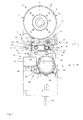
- the torque motor 12 is designed as an external rotor machine.
- the rotor 14 has an acting as the output shaft of the torque motor 12 hollow shaft 15 and is inserted with this hollow shaft directly on the door shaft 102, as shown by way of example in the Fig. 11 and FIG. 13 is shown.
- the stator 17 of the torque motor 12 is fixedly connected to a base plate 16 of a drive housing 100, which is secured with a torque arm (not shown) on the frame of the door against rotation.
- the drive housing 100 of the direct drive can be designed as a foot housing.
- the door shaft can then be coupled or connected via a plug connection with the hollow shaft 15.
- the brake device 18 as a brake a plurality of spring brakes 20, 21.
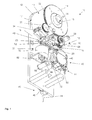
- Fig. 1 the base plate 16 is shown together with some essential elements of the door drive 10. On the base plate 16 of the torque motor 12 is mounted.
- the rotor 14 encloses as an external rotor the stator 17, which is therefore at least partially visible in the figures.
- the output shaft designed as a hollow shaft 15 is integrally arranged on the rotor 14.
- the hollow shaft 15 has a groove 24 for wedging a to be accommodated in the hollow shaft Torwelle 102 (only in the second embodiment in Fig. 11 shown).
- the hollow shaft 15 can be coupled directly to the door shaft 102.
- the braking device 18 is designed switchable by means of a switching device 31, as a switching device 31 acts here an electromagnet 32 which is energized simultaneously with the torque motor 12.
- an absolute encoder 34 is further provided on the rotor toothing 22, which is always coupled by a gear 36 geared to the rotor 14 and detected the rotational position of the rotor 14 by means of a Hall effect rotational angle sensor. This will be discussed later.
- a door drive control 38 see Fig. 12 .
- a frequency converter is arranged, by means of which the torque motor 12 is driven.
- target positions for the gate are stored in the door drive control 38 in nonvolatile memories, which - controlled by the absolute value transmitter 34 - can be controlled by means of the torque motor 12.
- a manual override device 40 is shown, by means of which the rotor 14 can be rotated manually and by means of which the brake 20 can be turned off for manual rotation.
- the manual override device 40 has a bearing 42 for a chain drive 44 which also acts as a first switching mechanism for the brake 20.
- the chain drive 44 is identical to that in the EP 1 028 223 B1 formed chain drive trained.
- the manual override device 40 as a second switching mechanism for switching the brake 20 is still a manual operation unit 46.
- the braking device 18 of the in Fig. 1 to 10 shown first embodiment with reference to the illustration in Fig. 2 which has been omitted for better illustration purposes, the electromagnet 32 and the chain drive 44 have been omitted.
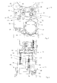
- the braking device 18 has the spring brake 21, 21 'and a spring loosening device 48.
- the spring brake 21 has the brake shaft 30, which has the gear 28 at one end, which meshes with the intermediate gear 26 and at another end has a further gear 50.
- two brake springs 52 are arranged to form the spring brake 21, 21 '. These are formed by a first leg spring 54 and a second leg spring 55. How best Fig. 4 can be seen, both leg springs 54, 55 a fixed to a holder 56 fixed end 57, 58, a winding portion 59, 60 and a leg 61, 62 on.
- the turn portions 59, 60 are each wound in opposite directions and wound around the shaft portion of the brake shaft 30.
- the dimensions are chosen so that the inner diameter of the two turn portions 59, 60 of the unloaded torsion springs 54, 55 before installation are slightly smaller than the outer diameter of the shaft portion of the brake shaft 30. The difference is between 0.2 and 0.5 mm.
- the winding regions 59, 60 of the torsion springs 54, 55 in the state of rest are biased against the shaft region of the brake shaft 30.
- additional or alternative to the bias of the leg springs 54, 55 separate biasing elements - as on the legs 61, 62 attacking -vortex to the winding portion 59, 60 of the brake springs 52 to press the associated brake shaft 30.
- the two legs 61, 62 tangentially from the brake shaft 30 and are detected by the spring loosening 48.
- the spring loosening device 48 has a respective cam 64, 65 per leg spring 54, 55.
- the two cams 64, 65 are mounted on a camshaft 66, which is rotatable by pivoting the bearing 42.
- the two legs 61, 62 take the camshaft 66 between them, so that upon rotation of the camshaft bent in the one direction of rotation of a leg 61 farther away and thus the associated winding portion 59 is released from the brake shaft, and upon rotation of the camshaft 66 in the opposite direction of the other leg 62 is bent away from the camshaft 66, whereby the other winding portion 60 is released in accordance with the brake shaft 30.
- the bearing 42 of the chain drive 44 is pivotally mounted about a pivot axis 68. At the opposite end, the bearing 42 is connected via a linkage 70 to the camshaft 66 of the spring loosening device 48. Like this in the EP 1 028 223 B1 explained in more detail and shown, engages a chain 72 of the chain drive 44 on a ring gear with internal teeth arranged with sprocket (not shown here). This ring gear is with play of an internal gear 74 on a centrally disposed shaft 76 (see Fig. 4 ) arranged around.
- the bearing 42 is by means of springs 78 in their in Fig. 3 and 4 shown center position where the Kettenhohlrad the internal gear 74 is not detected, biased.
- the bearing 42 When pulling on a strand of the chain 72, however, the bearing 42 is pivoted against the bias of the springs 78 about the pivot axis 78 in the pulling direction. As a result, the Kettenhohlrad engages the internal gear 74.
- the shaft 76 of the internal gear is, as in Fig. 4 is shown in detail, via an intermediate gear 80 with the further gear 50 of the brake shaft in engagement.
- the linkage 70 is adjusted such that a release of the corresponding leg spring 54, 55 from the brake shaft 30 takes place only when meshing between the internal gear 74 and the chain ring gear.
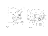
- the spring-loosening device 48 also has a slide 82, which acts on the two legs 61, 62 and can be displaced by means of the electromagnet 32.
- the legs 61, 62 are received in slots (not shown) of the slider 82, so that when the slider 82 in one direction (eg., Down in Fig. 7 ) only one leg 61 is moved to loosen the first leg spring 54, while the second leg 62 of the second leg spring 55 remains unmoved.
- the slider 82 is displaced in the opposite direction (for example, upward in FIG Fig. 7 ) only the second leg 62, namely that of the second leg spring 55 is then moved to loosen this second leg spring 55.
- the slider 82 can be moved by the electromagnet 32.
- the slider 82 is provided with a rod portion 84 which extends through the electromagnet 32 therethrough.
- the slider 82 by the switching mechanism of the manual operation device 40, so here by the manual operation unit 46 movable.
- a pin 86 engages on a pivot shaft 88 of the manual actuation unit 46.
- the manual actuator 46 on the back of the base plate 16 has a lever 90 which is connected to the pivot shaft 88 for common rotation and which is pivotable about a pulley construction 92 by means of a Bowden cable 94.
- the Bowden cable 94 can be operated by means of an emergency release device, which is not shown here, but just as in the DE 1 035 667 A1 , of the DE 102 56 480 A1 or the EP 1 418 296 B1 can be shown and shown configured.
- the absolute value transmitter 34 forms a door travel sensor 200, by means of which a position and a travel of the door leaf (not shown) connected to the door drive 10 can be detected by absolute position signals.
- the absolute value encoder 34 has a housing 202 in which a first rotation angle sensor 204 and a second rotation angle sensor 206 are accommodated. Both rotation angle sensors 204, 206 are designed as Hall rotation angle sensors.
- the first rotation angle sensor 204 has a first rotary element 208, which is connected via a transmission gear 210 to an input shaft 212 of the door travel sensor 200 with a large translation.
- the first rotary element 208 has a first magnet 216 seated on an output shaft 214 of the transmission gear 210.
- the first rotation angle sensor 204 has a first detection unit 218, which determines the rotational angle position of the first Detected magnet 216 and outputs a first gate position signal 220 in the form of a first voltage U 1 .
- This first gate position signal 220 is a signal that increases steadily monotonically with the rotational angle position of the first magnet 216.
- the transmission gear 210 has a transmission input shaft 222 and the output shaft 214.
- the transmission input shaft 222 is gearingly coupled to the input shaft 212, as indicated by two gears 224, 225.
- the ratio of the transmission 210 is more than 1: 100, for example between 1: 100 and 1: 150. For a rotation of the output shaft 214 thus more than 100 revolutions of the gear 36 are required.
- the translation 210 is selected such that in all conceivable door types to which the door drive 10 is to be connected, in the course of a total door movement between the ⁇ réellesend ein and the Scharchitected ein (or vice versa) no complete rotation of 360 ° degrees of the first magnet 216.
- the first door position signal 220 can always be assigned a specific position of the connected door leaf. It is always possible to determine the respective present door position on the adjacent door position signal.
- the second rotation angle sensor 206 has a second rotation angle element 226 that rotates many times faster than the first rotation element 208.
- the second rotary element 226 has a second magnet 228 which sits on the input shaft 212 and thus rotates at the same speed as the gear 36.
- the second rotation angle sensor 206 has a second detection unit 230.
- the second detection unit 230 is preferably designed as an absolute value sensor and is designed such that it generates from the present rotational angle position of the second magnet 228, a second position signal 232 in the form of a second voltage U 2 , which is a steadily increasing monotonically increasing function of the respective rotational angular position of the second magnet 228 is.
- Corresponding rotation angle sensors 206, 204 which generate continuously monotonous signals from rotational positions of magnets, are available on the market, for example, as Hall effect rotational angle sensors.
- Corresponding transmission gear 210 are available, for example, on the model market, for example, for aircraft model construction.
- FIG. 12 which illustrates a schematic diagram, can be seen, controls the door drive controller 38, the torque motor 12 based on the two position signals 220, 232.
- the first gate position signal 220 determines the door drive control 38, the respective door position.
- the properties of the driven gate are taught once.
- the end positions (closing end position and opening end position) are in this case taught in such a way that the door drive control 38 assigns the two end positions in each case a specific value of the first door position signal 220. In principle, however, it is also possible that corresponding end positions for different goals are already pre-stored.
- the door drive control 38 Based on the second position signal 232, the door drive control 38 receives very accurate intermediate values. From this signal also accurate speeds and accelerations of the rotor 14 can be derived and monitored.
- path-dependent speed profiles for the rotor 14 can be provided in the door drive control 38 in order to control the door leaf at different speeds as a function of the path.
- Corresponding control signals are applied to the torque motor 12 as control signals 240.
- the door drive control 38 can then monitor via the second rotation angle sensor whether the rotor 14 carries out corresponding movements. If the rotor movement deviates from the control commands, an error can be determined from this. In particular, in the illustrated configuration, smaller changes in speed of the rotor 14 can be detected, which are caused for example when the gate leaf to a relatively soft obstacle.
- the door operator control 38 can then respond by a corresponding shutdown. Overall, a very precise control of Troquemotors 12 and the connected thereto door is possible.
Abstract
Description
Die Erfindung betrifft eine Torantriebsvorrichtung mit den Merkmalen des Oberbegriffes des beigefügten Anspruches 1, wie sie beispielsweise in Form eines Wellentorantriebes bereits auf dem Markt erhältlich ist. Weiter betrifft die Erfindung einen Torwegsensor für eine solche Torantriebsvorrichtung, ein mit einer solchen Torantriebsvorrichtung versehenes Tor sowie ein Verfahren zum Steuern eines angetriebenen Tores.The invention relates to a door drive device with the features of the preamble of the appended claim 1, as it is already available for example in the form of a Wellentorantriebes on the market. Furthermore, the invention relates to a door travel sensor for such a door drive device, a door provided with such a door drive device and a method for controlling a driven door.
Die Erfindung liegt auf dem Gebiet von Torantrieben, mittels welchen ein Flügel eines Tores motorisch antreibbar ist. Hierzu gibt es ganz unterschiedliche Torantriebsvorrichtungen auf dem Markt. Beispielsweise gibt es sogenannte Schleppantriebe, bei denen ein Schlitten in einer Führungsschiene geführt wird und durch einen Motor hin- und hergehend angetrieben wird. An diesem Schlitten wird dann der Flügel angekoppelt. Solche Schleppantriebe sind häufig bei Garagentoren, insbesondere bei Einzel- oder Doppelgaragen, aufzufinden. Insbesondere bei größeren Toren, wie beispielsweise größeren Sektionaltoren für Sammelgaragen, Industrietoren oder auch Rolltoren gibt es bereits am Tor eine Torwelle, die über Seilzüge oder ein sonstiges Getriebe mit dem Flügel des Tores getrieblich verbunden ist. Beispielsweise ist die Torwelle Teil einer Gewichtsausgleichseinrichtung, wobei ein Federelement sich beim Senken des Flügels spannt. Für solche Tore gibt es die sogenannten Wellentorantriebe, deren Abtriebswelle unmittelbar oder unter Zwischenschaltung eines Getriebes, wie insbesondere eines Kettengetriebes, mit der Torwelle zur gemeinsamen Drehung gekoppelt werden könnten.The invention is in the field of gate drives, by means of which a wing of a gate is driven by a motor. For this purpose, there are very different door drive devices on the market. For example, there are so-called towing drives, in which a carriage is guided in a guide rail and is driven back and forth by a motor. On this slide then the wing is coupled. Such traction drives are often found in garage doors, especially in single or double garages. Especially with larger gates, such as larger sectional doors for collective garages, industrial doors or roller shutters, there is already a goal shaft at the gate, which is connected via cables or other gear with the wing of the door geared. For example, the door shaft is part of a weight balancing device, wherein a spring element is tensioned when lowering the wing. For such goals, there are the so-called Wellentorantriebe whose output shaft could be coupled directly or with the interposition of a transmission, such as in particular a chain gear, with the door shaft for common rotation.
Alle auf dem Markt befindlichen Torantriebe weisen einen vorzugsweise als Elektromotor ausgebildeten Motor mit einem Rotor auf, der über die zuvor erläuterten Getriebe sowie ein Motorgetriebe getrieblich mit dem Torflügel verbindbar ist.All available on the market door drives have a preferably designed as an electric motor motor with a rotor over the previously explained gear and a motor gearbox is geared to the door leaf connectable.
Durch Drehung des Rotors wird so der Torflügel zwischen seinen Endpositionen angetrieben. In der Regel sind die Getriebe derart, dass sich der Rotor bei einer Fahrt des Flügels zwischen den Endpositionen viele Male umdreht und beispielsweise mehr als 100 Umdrehungen durchführt.By rotation of the rotor so the gate is driven between its end positions. In general, the gearboxes are such that the rotor rotates many times during a travel of the wing between the end positions and, for example, performs more than 100 revolutions.
Nahezu alle auf dem Markt befindlichen Torantriebe weisen weiter einen Wegsensor oder Torpositionssensor auf, über den der Torantrieb gesteuert werden kann. In der Regel sind diese Wegsensoren als Drehwinkelsensoren ausgebildet, um die Drehung des Rotors oder eine damit getrieblich verbundenes Drehglied der Torantriebsvorrichtung zu erfassen.Virtually all door drives on the market continue to have a displacement sensor or door position sensor, which can be used to control the door drive. In general, these displacement sensors are designed as rotation angle sensors to detect the rotation of the rotor or a gear member rotatably connected thereto of the door drive device.
Beispielsweise ist auf einer mit dem Rotor verbundenen Motorwelle des Motors ein Inkremetalgeber vorgesehen. Dieser erzeugt, beispielsweise mittels einer Lochscheibe und einer Lichtschranke, bei einer Drehung des Rotors viele Impulse. Dem Inkremetalgeber ist beispielsweise in einer Torantriebssteuerung ein Zählwerk zugeordnet. Bei Drehung des Rotors werden die Impulse gezählt. Es wird dann nach der Montage des Torantriebes an dem anzutreibenden Flügel eine Lernfahrt durchgeführt, um die Zählerstände der Endpositionen und von sonstigen für die Steuerung interessierenden Torflügelpositionen zu ermitteln. Im Betrieb wird dann die Torantriebsvorrichtung anhand des jeweiligen Zählerstandes durchgeführt.For example, an incremental encoder is provided on a motor shaft of the motor connected to the rotor. This generates, for example by means of a perforated disc and a light barrier, upon rotation of the rotor many pulses. The incremental encoder is assigned, for example, in a door drive control a counter. Upon rotation of the rotor, the pulses are counted. After the door drive has been mounted on the wing to be driven, a learning run is then carried out in order to determine the counter readings of the end positions and of other door leaf positions of interest for the control. In operation, the door drive device is then carried out on the basis of the respective meter reading.
Diese Inkremetalgeber sind mit dem Nachteil verbunden, dass die Zählerstände insbesondere bei Stromausfall oder dergleichen Störfällen verloren gehen. Auch sind solche Inkrementalgeber teils ungenau, so dass sie öfters im Verlauf des Betriebs des Torantriebes wieder geeicht werden müssen. Man hat hierzu beispielsweise bereits einen Referenzpunktgeber vorgeschlagen, der an einer bestimmten Position des Torflügels oder eines Getriebeelements vorgesehen ist und bei Passieren dieses Punktes im Verlauf des Torweges ein Referenzsignal abgibt, mit dem das Zählwerk bei jeder Fahrt erneut abgeglichen werden kann. Hier besteht aber der Nachteil des zusätzlichen Montage- und Verdrahtungsaufwandes des Referenzgebers.These incremental encoders are associated with the disadvantage that the counter readings are lost, in particular in the event of a power failure or similar malfunctions. Also, such incremental encoders are sometimes inaccurate, so that they often have to be calibrated again in the course of the operation of the door drive. For this purpose, for example, it has already been proposed, for example, a reference point sensor, which is provided at a specific position of the door leaf or a transmission element and when passing this point in the course of Torweges outputs a reference signal with which the counter can be adjusted again with each ride. Here, however, there is the disadvantage of additional installation and wiring costs of the reference encoder.
Es besteht daher vielfach der Wunsch, anstelle der Inkremetalgeber, die nur eine relative Torposition ermitteln, Absolutwertgeber vorzusehen, die ein Positionssignal liefern, das stets auf eine bestimmte Torposition hindeutet. Das Positionssignal des Absolutwertgebers soll insbesondere eine stetig monotone Funktion der Position des angeschlossenen Torflügels darstellen, um die eindeutige Zuordnung von Signal und Position zu ermöglichen.There is therefore often the desire, instead of the incremental encoders, which determine only a relative gate position, to provide absolute encoders which deliver a position signal which always indicates a certain gate position. In particular, the position signal of the absolute value encoder should represent a continuous, monotonous function of the position of the connected door leaf in order to enable the unambiguous assignment of signal and position.
Hier gibt es bereits Wellentorantriebe auf dem Markt, die insbesondere als Industrietortriebe einsetzbar sind und die als Absolutwertgeber einen auf dem Hall-Effekt beruhenden Drehwinkelsensor aufweisen.Here there are already Wellentorantriebe on the market, which can be used in particular as Industrietortriebe and have as an absolute encoder based on the Hall effect angle of rotation sensor.
Der Drehwinkelsensor des Absolutwertgebers hat als Drehelement beispielsweise einen auf einer Drehwelle angebrachten Magneten. Die Stellung des Magneten wird unter Ausnutzung des Hall-Effektes erfasst, und daraus wird ein Positionssignal erzeugt. Damit dieses Positionssignal eine stetig monotone Funktion der Torposition darstellt und so immer einen absoluten Wert einer bestimmten Torposition angibt, darf sich dieses Drehelement im Verlauf des gesamten Torweges von der einen Endposition (zum Beispiel der Schließposition) zu der anderen Endposition (zum Beispiel der Öffnungsposition) um nicht mehr als 360° Grad drehen. Würde das Drehelement mehr als eine volle Umdrehung machen, beispielsweise eine Drehung von 370° Grad, dann würde das Ausgangssignal dem gleichen Signal entsprechen, wie bei der Stellung von 10° Grad. Somit hätte man wiederum nur eine relative Torposition, wobei der Absolutwert wiederum nur anhand von weiteren Informationen, beispielsweise ermittelt durch ein Zählwerk, erhältlich ist.The rotation angle sensor of the absolute value encoder has as a rotary element, for example, a magnet mounted on a rotary shaft. The position of the magnet is detected by taking advantage of the Hall effect, and from this a position signal is generated. In order for this position signal to represent a continuous, monotonous function of the gate position and thus always indicate an absolute value of a specific gate position, this rotary element may move from one end position (for example the closed position) to the other end position (for example the open position) during the entire door path. do not turn more than 360 °. If the rotary element made more than one complete revolution, for example a rotation of 370 degrees, then the output signal would correspond to the same signal as at the position of 10 degrees. Thus, one would again only have a relative gate position, the absolute value in turn being obtainable only on the basis of further information, for example determined by a counter.
Der Oberbegriff des beigefügten Patentanspruches 1 geht als Stand der Technik von einem solchen Wellentorantrieb mit einem entsprechend langsam drehenden Absolutwertgeber aus.The preamble of appended claim 1 is known in the art of such a Wellentorantrieb with a correspondingly slowly rotating absolute encoder.
Demnach bilden solche Wellentorantriebe eine Torantriebsvorrichtung mit einem Motor, welche einen Rotor aufweist. Der Rotor ist - beispielsweise über ein Getriebe in der Torantriebsvorrichtung sowie eine Torwelle getrieblich mit dem anzutreibenden Torflügel verbindbar.Accordingly, such Wellentorantriebe form a door drive device with a motor having a rotor. The rotor is - for example via a transmission in the door drive device and a door shaft geared with the gate to be driven connectable.
Der bekannte Absolutwertgeber bildet einen ersten Drehwinkelsensor, mit dem die aktuelle Torposition anhand eines Torpositionssignal bestimmbar ist. Damit dieses Torpositionssignal zum Zwecke einer genaueren Steuerung stets einer bestimmten Torposition zuordenbar ist, ist der Drehwinkelsensor derart über ein Untersetzungsgetriebe an dem Rotor oder ein sich damit drehendes Drehglied angeschlossen, dass eine gesamte Bewegung eines anzuschließenden Torflügels zwischen dessen Endpositionen weniger als 360° Grad des sich zur Drehwinkelerfassung drehenden Drehelements des ersten Drehwinkelsensors bewirkt.The known absolute encoder forms a first rotation angle sensor with which the current door position can be determined by means of a gate position signal. So that this gate position signal for the purpose of a more precise control is always assigned to a specific gate position, the rotation angle sensor is connected via a reduction gear on the rotor or a rotary member rotating therewith such that a total movement of a gate to be connected between its end positions less than 360 ° of causes the rotation angle detection rotating rotary element of the first rotation angle sensor.
Solche Torantriebe weisen zwar den Vorteil eines Torpositionssignals auf, welches stets einer bestimmten Torposition zuordenbar ist, jedoch ist dieses Torpositionssignal für viele Steuerungs- und Überwachungszwecke zu ungenau.Although such gate drives have the advantage of a gate position signal, which is always a specific gate position can be assigned, but this gate position signal is too imprecise for many control and monitoring purposes.
Aufgabe der Erfindung ist es, eine Torantriebsvorrichtung mit dem Merkmalen des Oberbegriffes des beigefügten Anspruches 1 derart zu verbessern, dass sie exakter steuerbar und/oder überwachbar ist.The object of the invention is to improve a door drive device with the features of the preamble of the attached claim 1 such that it is more precisely controlled and / or monitored.
Diese Aufgabe wird durch eine Torantriebsvorrichtung mit den Merkmalen des Anspruches 1 gelöst.This object is achieved by a door drive device with the features of claim 1.
Vorteilhafte Ausgestaltungen der Erfindung sind Gegenstand der Unteransprüche.Advantageous embodiments of the invention are the subject of the dependent claims.
Ein Torwegsensor zur Verwendung in einer solchen Torantriebsvorrichtung, ein mit einer solchen Torantriebsvorrichtung und/oder mit einem solchen Torwegssensor versehenes Tor sowie ein Steuerungsverfahren hierfür sind in den Nebenansprüchen angegeben.A door travel sensor for use in such a door drive device, a door provided with such a door drive device and / or with such a door travel sensor and a control method therefor are indicated in the dependent claims.
Bei einer erfindungsgemäßen Torantriebsvorrichtung ist - wie dies im Stand der Technik grundsätzlich bekannt ist -, ein Drehwinkelsensor mit einem sich langsam, maximal um 360° drehenden Drehelement vorgesehen.In a door drive device according to the invention, as is basically known in the prior art, a rotation angle sensor is provided with a rotary element rotating at a maximum of 360 °.
Dieser Drehwinkelsensor wird im Folgenden als erster Drehwinkelsensor bezeichnet, und sein Drehelement wird im Folgenden als erstes Drehelement bezeichnet.This rotation angle sensor will be referred to as a first rotation angle sensor hereinafter, and its rotary element will be referred to as a first rotary element hereinafter.
Mit diesem ersten Drehwinkelsensor kann ein erstes Torpositionssignal erzeugt werden, welches eine stetig monotone Funktion einer Torposition eines an die Torantriebsvorrichtung anzuschließenden Torflügels erzeugt.With this first rotation angle sensor, a first gate position signal can be generated, which generates a continuous monotonous function of a gate position of a door leaf to be connected to the door drive device.
Erfindungsgemäß ist noch ein zweiter Drehwinkelsensor mit einem zweiten Drehelement zur Drehwinkelerfassung vorgesehen, das ebenfalls mit dem Rotor und/oder sich damit drehenden Drehgliedes getrieblich verbunden ist, jedoch derart, dass es sich um ein Vielfaches schneller dreht als das erste Drehelement des ersten Drehwinkelsensors.According to the invention, a second rotation angle sensor is provided with a second rotary element for detecting the rotation angle, which is likewise connected in a gear to the rotor and / or rotary member rotating therewith, but such that it rotates much faster than the first rotary element of the first rotation angle sensor.
Somit kann mittels des ersten Drehwinkelsensors ein erstes Torpositionssignal erzeugt werden, welches die Torposition absolut angibt. Mit dem Signal des zweiten Drehwinkelsensors können viele Zwischenpositionen angegeben werden, ohne dass hierzu Zählerstände gespeichert werden müssen.Thus, by means of the first rotation angle sensor, a first door position signal can be generated which indicates the door position absolutely. With the signal of the second rotation angle sensor, many intermediate positions can be specified without having to store counter readings.
Anhand der beiden Torsignale kann man so sehr genau die Torposition absolut bestimmen, auch wenn der erste Drehwinkelsensor kein sehr genaues Signal abgeben sollte.On the basis of the two gate signals, one can determine the position of the gate absolutely exactly, even if the first rotation angle sensor should not deliver a very accurate signal.
Durch den sich schneller drehenden zweiten Drehwinkelsensor können weiter auch kleinere Fluktuationen oder Änderungen in der Geschwindigkeit des Motors erfasst werden.By the faster rotating second rotation angle sensor, even smaller fluctuations or changes in the speed of the engine can be detected.
Insgesamt sind der Motor und/oder das angetriebene Tor so über den zweiten Drehwinkelsensor sehr genau überwachbar.Overall, the motor and / or the driven door can be very accurately monitored via the second angle of rotation sensor.
Der erste und/oder der zweite Drehwinkelsensor sind vorzugsweise als Absolutwertsensoren ausgebildet, die ein Signal liefern, welches eine stetig monotone Funktion der Drehwinkelposition des jeweiligen Drehelements darstellt.The first and / or the second rotation angle sensor are preferably designed as absolute value sensors which supply a signal which represents a continuous monotonous function of the rotational angle position of the respective rotary element.
Beispielsweise wird ein Spannungssignal abgegeben, das mit dem Drehwinkel des Drehelements stetig monoton ansteigt.For example, a voltage signal is output, which increases steadily monotonically with the rotation angle of the rotary member.
Dadurch lässt sich jedem Drehwinkel genau ein Signal zuordnen und umgekehrt.As a result, exactly one signal can be assigned to each rotation angle and vice versa.
Vorzugsweise sind die Drehwinkelsensoren Hall-Sensoren, wie dies grundsätzlich bei Absolutwertgebern bereits Stand der Technik ist. Solche Hall-Sensoren sind leichtgängig und wartungsfrei, außerdem können sie - im Gegensatz zum Beispiel zu Potentiometern - beliebig oft herumgedreht werden.Preferably, the rotation angle sensors Hall sensors, as is basically already in prior art absolute value encoders. Such Hall sensors are smooth and maintenance-free, and they can - as opposed to potentiometers, for example - be turned around as often as desired.
Wenngleich die Drehwinkelsensoren an unterschiedlichen Stellen der Torantriebsvorrichtung jeweils einzeln vorgesehen werden können, so ist besonders bevorzugt, die beiden Drehwinkelsensoren in einer Einheit zusammenzufassen. Beispielsweise ist in der Torantriebsvorrichtung ein Torwegssensor vorgesehen, in dem beide Drehwinkelsensoren vereinigt sind. Dieser vorzugsweise als Absolutwertgeber ausgebildete Torwegsensor weist in bevorzugter Ausgestaltung eine Eingangswelle auf. Die Eingangswelle kann mit einem Eingangsdrehelement zur Kopplung an ein Drehglied der Torantriebsvorrichtung versehen sein. Beispielsweise ist ein Zahnrad als Eingangsdrehelement vorgesehen, mit dem die Eingangswelle auch unmittelbar mit dem Rotor verbindbar ist. An der Eingangswelle greift einerseits das sich schneller drehende zweite Drehelement des zweiten Drehwinkelsensors an. An der Eingangswelle ist andererseits auch ein Übersetzungsgetriebe vorgesehen, dessen Ausgangswelle um ein Vielfaches langsamer dreht als die Eingangswelle.Although the rotation angle sensors can be provided individually at different locations of the door drive device, it is particularly preferred to combine the two rotation angle sensors in one unit. For example, a Torwegssensor is provided in the door drive device, in which both rotation angle sensors are combined. This preferably designed as an absolute value sensor gate travel sensor has in a preferred embodiment, an input shaft. The input shaft may be provided with an input rotary member for coupling to a rotary member of the door drive device. For example, a gear is provided as an input rotary member, with which the input shaft is also directly connected to the rotor. On the one hand, the faster rotating second rotary element of the second rotation angle sensor engages on the input shaft. On the other hand, a transmission gear is provided on the input shaft, whose output shaft rotates by a multiple slower than the input shaft.
An dieser Ausgangswelle greift dann das erste Drehelement des ersten Drehwinkelsensors an.At this output shaft then attacks the first rotary element of the first rotation angle sensor.
Das Übersetzungsverhältnis zwischen dem ersten Drehelement und dem zweiten Drehelement wird derart gewählt, dass eine genaue Erfassung auch kleiner Verdrehungen des Rotors durch das zweite Drehelement erfassbar ist, andererseits aber das erste Drehelement sich maximal um 360° Grad im Verlauf der Torbewegung dreht.The transmission ratio between the first rotary element and the second rotary element is chosen such that an accurate detection of small rotations of the rotor by the second rotary element can be detected, but on the other hand, the first rotary member rotates a maximum of 360 ° in the course of the door movement.
Die meisten Torantriebe sind zum Anschließen an unterschiedliche Tore oder Torantriebsarten vorgesehen. Das Übersetzungsverhältnis wird daher so ausgewählt, dass auch bei der maximal denkbaren Umdrehungszahl des Rotors bei einer Torfahrt zwischen den Endpositionen keine volle Drehung des ersten Drehelements erreicht wird. Wird dann ein kleineres Tor oder ein anderes Zwischengetriebe verwendet, so dass sich der Rotor bei einer Torfahrt entsprechend weniger dreht, wird eine volle Drehfahrt beispielsweise nur zu einer Winkelverstellung von 270° Grad oder auch nur 180° Grad führen.Most door operators are designed for connection to different gates or door types. The gear ratio is therefore selected so that no full rotation of the first rotary element is achieved even when the maximum conceivable number of revolutions of the rotor in a Torfahrt between the end positions. If a smaller gate or another intermediate gear is then used, so that the rotor rotates correspondingly less during a door drive, a full turning drive will lead, for example, only to an angle adjustment of 270 ° or even only 180 °.
Eine dadurch grundsätzlich bedingte geringere Genauigkeit des ersten Drehwinkelsensors, der die gesamte Torfahrt auf entsprechend weniger Drehwinkelgraden abbilden muss, wird durch das Vorsehen des zweiten Drehwinkelsensors mehr als kompensiert.A basically conditional lower accuracy of the first rotation angle sensor, which must map the entire door travel on correspondingly less rotation angle degrees, is more than compensated by the provision of the second rotation angle sensor.
Entsprechende kleine Getriebe für den Torwegsensor sind auf dem Markt beispielsweise für den Modelbau erhältlich.Corresponding small gears for the Torwegsensor are available on the market, for example, for model making.
Anhand der beiden Drehwinkelsignale lässt sich eine sehr genaue Steuerung durchführen. Aufgrund des sich sehr schnell drehenden zweiten Drehelementes können auch geringe Änderungen in der Geschwindigkeit des Rotors sofort erfasst werden. Beispielsweise würde bei einem Auftreffen des Torflügels auf ein relativ weiches Hindernis - beispielsweise eine Person - sich zunächst die Geschwindigkeit nur sehr gering ändern.Based on the two rotation angle signals, a very precise control can be carried out. Due to the very fast rotating second rotary element even small changes in the speed of the rotor can be detected immediately. For example, if the door leaf strikes a relatively soft obstacle-for example, a person-the speed would initially only change very slightly.
Dennoch könnte eine solche geringe Geschwindigkeitsänderung aufgrund des zweiten Drehwinkelsensors sofort erfasst werden und ein Stoppen der Torantriebsvorrichtung wegen Auflaufen auf ein Hindernis eingeleitet werden.Nevertheless, such a small speed change due to the second rotation angle sensor could be detected immediately and a stop of the door drive device due to running on an obstacle can be initiated.
Die beiden unterschiedlich drehenden Drehwinkelsensoren und/oder der erläuterte Torwegsensor mit diesen Drehwinkelsensoren hat besondere Vorteile in Verbindung mit Torquemotoren oder Direktantrieben, wo ein Rotor vorzugsweise getriebelos unmittelbar an einer Torwelle angreift.The two differently rotating rotation angle sensors and / or the described door travel sensor with these rotation angle sensors has particular advantages in connection with torque motors or direct drives, where a rotor preferably engages gearless directly on a door shaft.
Dadurch werden Rotorbewegungen und Rotorpositionen erfasst, die aufgrund eines fehlenden Zwischengetriebes sehr viel genauer die Bewegung eines Torflügels wiedergeben. Dadurch kann auch der Torflügel sehr direkter gesteuert und überwacht werden.As a result, rotor movements and rotor positions are detected, which reflect due to a missing intermediate gear much more accurately the movement of a gate. This also allows the door leaf to be controlled and monitored very directly.
Ein Ausführungsbeispiel der Erfindung wird nachfolgend anhand der beigefügten Zeichnung näher erläutert. Darin zeigt:
- Fig. 1
- eine perspektivische Ansicht einer ersten Ausführungsform einer Torantriebsvorrichtung zum Antreiben einer Torwelle;
- Fig. 2
- eine perspektivische Ansicht der ersten Ausführungsform der Torantriebsvorrichtung vergleichbar der Ansicht von
Fig. 1 , wobei einige Elemente zu Darstellungszwecken weggelassen worden sind; - Fig. 3
- eine Vorderansicht auf die Torantriebsvorrichtung von
Fig. 1 , - Fig. 4
- eine Seitenansicht der Torantriebsvorrichtung von
Fig. 1 ; - Fig. 5
- eine Rückansicht der Torantriebsvorrichtung von
Fig. 1 ; - Fig. 6
- eine geschnittene Draufsicht auf die Torantriebsvorrichtung von
Fig. 1 ; - Fig. 7
- eine Detailansicht von vorne auf einen Teilbereich der Torantriebsvorrichtung von
Fig. 1 ; - Fig. 8
- der Teilbereich von
Fig. 7 von der Seite gesehen; - Fig. 9
- eine Detailansicht eines Teilbereichs der Rückansicht von
Fig. 5 ; und - Fig. 10
- der Teilbereich von
Fig. 7 von vorne, wobei einige Elemente zu Darstellungszwecken weggelassen worden sind; - Fig. 11
- eine schematische Darstellung eines bei der Torantriebsvorrichtung verwendbaren Absolutwertgebers; und
- Fig. 12
- eine schematische Darstellung des Absolutwertgebers zusammen mit einer Torantriebsteuerung zum Steuern der Torantriebsvorrichtung.
- Fig. 1
- a perspective view of a first embodiment of a door drive device for driving a door shaft;
- Fig. 2
- a perspective view of the first embodiment of the door drive device comparable to the view of
Fig. 1 with some elements omitted for illustrative purposes; - Fig. 3
- a front view of the door drive device of
Fig. 1 . - Fig. 4
- a side view of the door drive device of
Fig. 1 ; - Fig. 5
- a rear view of the door drive device of
Fig. 1 ; - Fig. 6
- a sectional plan view of the door drive device of
Fig. 1 ; - Fig. 7
- a detail view from the front of a portion of the door drive device of
Fig. 1 ; - Fig. 8
- the subarea of
Fig. 7 seen from the side; - Fig. 9
- a detailed view of a portion of the rear view of
Fig. 5 ; and - Fig. 10
- the subarea of
Fig. 7 from the front, with some elements omitted for illustrative purposes; - Fig. 11
- a schematic representation of a usable in the door drive absolute value encoder; and
- Fig. 12
- a schematic representation of the absolute value encoder together with a Torantriebsteuerung for controlling the door drive device.
Der in den
Die in den Figuren als Beispiel für Torantriebsvorrichtungen dargestellten Torantriebe 10 weisen in allen ihren unterschiedlichen Ausführungsformen als Elektromotor einen Torquemotor (Direktantrieb) 12 auf.The gate drives 10 shown in the figures as an example of door drive devices have a torque motor (direct drive) 12 in all their different embodiments as an electric motor.
Wie dies zum Beispiel näher in "EBERLEIN, W; BARAN: "Besser direkt", in WISSENSPORTAL baumaschine.de, 1(2005)" beschrieben ist, sind Torquemotoren Direktmotoren, welche direkt auf Antriebswellen von Maschinen ohne Zwischenglieder wie Getriebe, Riemen oder Kupplungen montiert werden. Für weitere Einzelheiten zu Torquemotoren wird ausdrücklich auf die vorerwähnte Literaturstelle verwiesen. Die wichtigsten Bauelemente eines Torquemotors sind ein Stator und ein Rotor. Ein Torquemotor kann vereinfacht als ein auf hohe Drehmomente optimierter, großer Servomotor mit Hohlwelle betrachtet werden.For example, as described in more detail in "EBERLEIN, W; BARAN:" Better Direct ", in WISSENSPORTAL baumaschine.de, 1 (2005)", torque motors are direct motors which directly on drive shafts of machines without intermediate links such as gears, belts or clutches to be assembled. For further details on torque motors, reference is expressly made to the aforementioned reference. The most important components of a torque motor are a stator and a rotor. A torque motor can be considered simplified as a high torque optimized, large servomotor with hollow shaft.
Bei den dargestellten Beispielen wird ein hochpoliger Synchronmotor 13 als Torquemotor 12 verwendet.In the illustrated examples, a high-pole
Der Torquemotor 12 erzeugt das Drehmoment, welches zum Heben und Senken des Tores (nicht dargestellt - die Ausbildung des Tores ist analog zu dem in der
Dabei kann der Torquemotor 12 als Außenläufer- oder Innenläufermaschine ausgeführt sein. Der Rotor 14 des Torquemotors (Direktantriebes) ist vorzugsweise direkt oder gekuppelt, aber besonders bevorzugt ohne eine zusätzliche Übersetzung, mit der Torwelle - zum Beispiel Torsionsfederwelle eines Sektional- oder Kipptores oder dergleichen) verbunden. Drehen des Rotors 14 durch das wandernde elektromagnetische Feld bewirkt das Drehen der Torwelle 102. Dabei sind Drehzahl und Drehmoment von Rotor 14 und Torwelle 102 vorzugsweise identisch.In this case, the
Im Fall des Auslösens eines Krafteinwirkungsschutz-Sensors (nicht dargestellt) erhält der Torquemotor 12 durch eine Ansteuerungselektronik - Torantriebssteuerung 38 siehe Fig. 15 - ein Signal zur sofortigen Drehrichtungsumkehr, und die Drehrichtung des Rotors 14 und damit der Torwelle wird sofort (in Sekundenbruchteilen) umkehrt.In the case of triggering a force action protection sensor (not shown) receives the
In den in den Figuren dargestellten Beispielen ist der Torquemotor 12 als Außenläufermaschine ausgeführt. Der Rotor 14 hat eine als Abtriebswelle des Torquemotors 12 wirkende Hohlwelle 15 und wird mit dieser Hohlwelle direkt auf die Torwelle 102 gesteckt, wie dies beispielhaft in den
Alternativ kann das Antriebsgehäuse 100 des Direktantriebes als Fußgehäuse ausgeführt werden. Die Torwelle kann dann gekuppelt oder über eine Steckverbindung mit der Hohlwelle 15 verbunden werden.Alternatively, the
Bei den bevorzugten Ausgestaltungen des Torantriebes 10, wie sie in den beigefügten Figuren wiedergegeben sind, sind neben der Hauptfunktion "Heben und Senken des Tores" folgende Sicherheitsfunktionen integriert:
- Halten des Tores in einer Halteposition (Tor geschlossen oder Tor offen),
- Halten des Tores bei Federbruch (Ausfall einer
Gewichtsausgleichseinrichtung des Tores) und Stromausfall, - Fangen (Bremsen) und Halten des Tores bei Federbruch während der Bewegung,
- Krafteinwirkungsschutz von Personen und Gegenständen während der Schließbewegung und
- Handbetätigung zum Öffnen und Schließen des Tores z.B. bei einem Stromausfall oder bei der Montage.
- Holding the gate in a stop position (gate closed or gate open),
- Holding the gate in case of spring breakage (failure of a
Counterweight device of the gate) and power failure, - Catching (braking) and holding the gate during spring break during the movement,
- Force impact protection of persons and objects during the closing movement and
- Manual operation for opening and closing the door, eg during a power failure or during assembly.
Das Halten des Tores in einer Halteposition erfolgt durch eine Bremseinrichtung 18 mit einer Bremse 20.The holding of the gate in a holding position by a
Bei der in den
In
Weiter ist an dem Rotor 14 die als Hohlwelle 15 ausgebildete Abtriebswelle integral angeordnet. Die Hohlwelle 15 weist eine Nut 24 zum Verkeilen einer in der Hohlwelle aufzunehmenden Torwelle 102 (nur bei dem zweiten Ausführungsbeispiel in
An der Rotorverzahnung 22 greift ein Zwischenzahnrad 26 und an dem Zwischenzahnrad 26 ein Zahnrad 28 einer Bremswelle 30 der Bremseinrichtung 18 an.At the
Die Bremseinrichtung 18 ist mittels einer Schalteinrichtung 31 schaltbar ausgebildet, als Schalteinrichtung 31 wirkt hier ein Elektromagnet 32, der gleichzeitig mit dem Torquemotor 12 bestromt wird.The
Wie aus den
In
Die Handbetätigungseinrichtung 40 weist eine auch als ein erster Schaltmechanismus für die Bremse 20 wirkende Lagerung 42 für einen Kettentrieb 44 auf. Der Kettentrieb 44 ist identisch zu dem in der
Weiter weist die Handbetätigungseinrichtung 40 als zweiten Schaltmechanismus zum Schalten der Bremse 20 noch eine Manualbetätigungseinheit 46 auf.Next, the
Im Folgenden wird die Bremseinrichtung 18 des in den
Die Federbremse 21 weist die Bremswelle 30 auf, die an einem Ende das Zahnrad 28 aufweist, das mit dem Zwischenzahnrad 26 kämmt und an einem anderen Ende ein weiteres Zahnrad 50 aufweist. An einem dazwischen angeordneten Wellenbereich sind zum Bilden der Federbremse 21, 21' zwei Bremsfedern 52 angeordnet. Diese werden durch eine erste Schenkelfeder 54 und eine zweite Schenkelfeder 55 gebildet. Wie am besten aus
Dadurch liegen die Windungsbereiche 59, 60 der Schenkelfedern 54, 55 im Ruhezustand vorgespannt an dem Wellenbereich der Bremswelle 30 an. In einer nicht dargestellten alternativen Ausgestaltung sind zusätzlich oder alternativ zu der Vorspannung der Schenkelfedern 54, 55 gesonderte Vorspannelemente - etwa an den Schenkeln 61, 62 angreifend -vorgesehen, um den Windungsbereich 59, 60 der Bremsfedern 52 auf die zugeordnete Bremswelle 30 zu drücken. Wie in den
Die Federlockerungseinrichtung 48 weist je eine Nocke 64, 65 pro Schenkelfeder 54, 55 auf. Die beiden Nocken 64, 65 sind an einer Nockenwelle 66 gelagert, die durch Verschwenkung der Lagerung 42 verdrehbar ist.The
Die beiden Schenkel 61, 62 nehmen die Nockenwelle 66 zwischen sich auf, so dass bei Verdrehung der Nockenwelle in die eine Drehrichtung der eine Schenkel 61 weiter weg gebogen und somit der zugeordnete Windungsbereich 59 von der Bremswelle gelöst wird, und bei Drehung der Nockenwelle 66 in die entgegengesetzte Richtung der andere Schenkel 62 von der Nockenwelle 66 weggebogen wird, wodurch der andere Windungsbereich 60 entsprechend von der Bremswelle 30 gelöst wird.The two
Wie am besten aus
Bei Zug an einem Strang der Kette 72 wird die Lagerung 42 jedoch entgegen die Vorspannung der Federn 78 um die Schwenkachse 78 in Zugrichtung verschwenkt. Dadurch gelangt das Kettenhohlrad in Eingriff mit dem Innenzahnrad 74. Die Welle 76 des Innenzahnrades ist, wie dies in
Über die Bremswelle 30 und das Zwischenzahnrad 26 ist so die Welle 76 der Handbetätigungseinrichtung 40 mit der Rotorverzahnung 22 in Eingriff.Via the
Das Gestänge 70 ist derart eingestellt, dass erst bei Eingriff zwischen Innenzahnrad 74 und Kettenhohlrad ein Lösen der entsprechenden Schenkelfeder 54, 55 von der Bremswelle 30 erfolgt.The
Die Federlockerungseinrichtung 48 weist neben der Nockenwelle 66 mit den beiden Nocken 64, 65 noch einen an den beiden Schenkeln 61, 62 angreifenden, mittels des Elektromagneten 32 verschiebbaren Schieber 82 auf. Die Schenkel 61, 62 sind in Langlöchern (nicht dargestellt) des Schiebers 82 aufgenommen, so dass bei Zug des Schiebers 82 in die eine Richtung (z. B. nach unten in
Wie erläutert kann der Schieber 82 durch den Elektromagneten 32 bewegt werden. Hierzu ist der Schieber 82 mit einem Stangenbereich 84 versehen, welcher sich durch den Elektromagneten 32 hindurch erstreckt. Weiter ist der Schieber 82 durch den Schaltmechanismus der Handbetätigungseinrichtung 40, also hier durch die Manualbetätigungseinheit 46 bewegbar. Hierzu greift an dem Schieber 82, hier an dem Stangenbereich 84 an dem entgegengesetzten Ende, ein Stift 86 an einer Schwenkwelle 88 der Manualbetätigungseinheit 46 an.As explained, the
Wie aus
Der Bowdenzug 94 lässt sich mittels einer Notentriegelungsvorrichtung bedienen, die hier nicht weiter dargestellt ist, jedoch genauso wie in der
Durch Zug an dem Bowdenzug 94 wird der Hebel 90 verschwenkt. Dadurch wird die Schwenkwelle 88 verschwenkt, so dass über den Stift 86 der Schieber 82 bewegt wird, um so eine der Schenkelfedern 54, 55 zu lockern und damit die Bremseinrichtung 18 zu lösen. Dadurch kann ein an die Hohlwelle 15 angeschlossenes Tor ohne Entkupplung der Torwelle 102 von dem Rotor 14 und damit ohne Entkupplung von dem Absolutwertgeber 34 manuell bewegt werden.By train on the
In der
Der erste Drehwinkelsensor 204 weist ein erstes Drehelement 208 auf, welches über ein Übersetzungsgetriebe 210 an eine Eingangswelle 212 des Torwegsensors 200 mit einer großen Übersetzung angeschlossen ist. Das erste Drehelement 208 weist einen auf einer Ausgangswelle 214 des Übersetzungsgetriebes 210 sitzenden ersten Magneten 216 auf. Weiter weist der erste Drehwinkelsensor 204 eine erste Erfassungseinheit 218 auf, die die Drehwinkelstellung des ersten Magneten 216 erfasst und ein erstes Torpositionssignal 220 in Form einer ersten Spannung U1 abgibt. Dieses erstes Torpositionssignal 220 ist ein Signal, das mit der Drehwinkelstellung des ersten Magneten 216 stetig monoton ansteigt.The first rotation angle sensor 204 has a first rotary element 208, which is connected via a transmission gear 210 to an
Das Übersetzungsgetriebe 210 weist eine Getriebeeingangswelle 222 und die Ausgangswelle 214 auf. Die Getriebeeingangswelle 222 ist getrieblich mit der Eingangswelle 212 gekoppelt, wie dies durch zwei Zahnräder 224, 225 angedeutet ist.The transmission gear 210 has a
Die Übersetzung des Übersetzungsgetriebes 210 beträgt mehr als 1:100 beispielsweise zwischen 1:100 und 1:150. Für eine Umdrehung der Ausgangswelle 214 werden somit mehr als 100 Umdrehungen des Zahnrades 36 benötigt. Insgesamt wird die Übersetzung 210 derart gewählt, dass bei allen denkbaren Torarten, an die der Torantrieb 10 anzuschließen ist, im Verlauf einer gesamten Torbewegung zwischen der Öffnungsendstellung und der Schließendstellung (oder umgekehrt) keine gesamte Volldrehung von 360° Grad des ersten Magneten 216 erfolgt. Auf diese Weise lässt sich dem ersten Torpositionssignal 220 stets eine bestimmte Position des angeschlossenen Torflügels zuordnen. Man kann stets an dem anliegenden Torpositionssignal die jeweils vorliegende Torposition bestimmen.The ratio of the transmission 210 is more than 1: 100, for example between 1: 100 and 1: 150. For a rotation of the
Der zweite Drehwinkelsensor 206 weist ein zweites Drehwinkelelement 226 auf, welches sich um ein Vielfaches schneller als das erste Drehelement 208 dreht. Das zweite Drehelement 226 weist einen zweiten Magneten 228 auf, der auf der Eingangswelle 212 sitzt und sich somit gleich schnell wie das Zahnrad 36 dreht. Weiter weist der zweite Drehwinkelsensor 206 eine zweite Erfassungseinheit 230 auf. Auch die zweite Erfassungseinheit 230 ist vorzugsweise als Absolutwertsensor ausgebildet und ist derart ausgebildet, dass sie aus der vorliegenden Drehwinkelposition des zweiten Magneten 228 ein zweites Positionssignal 232 in Form einer zweiten Spannung U2 erzeugt, die eine stetig monoton ansteigende Funktion der jeweiligen Drehwinkelposition des zweiten Magneten 228 ist. Entsprechende Drehwinkelsensoren 206, 204, die aus Drehwinkelstellungen von Magneten stetig monotone Signale erzeugen, sind beispielsweise als Hall-Effekt-Drehwinkelsensoren auf dem Markt erhältlich.The second
Entsprechende Übersetzungsgetriebe 210 sind beispielsweise auf dem Modellbaumarkt, beispielsweise zum Flugzeugmodellbau, erhältlich.Corresponding transmission gear 210 are available, for example, on the model market, for example, for aircraft model construction.
Wie insbesondere aus
Es können insbesondere in der Torantriebssteuerung 38 wegabhängige Geschwindigkeitsprofile für den Rotor 14 vorgesehen werden, um den Torflügel wegabhängig unterschiedlich schnell zu steuern. Entsprechende Steuerungssignale werden als Steuersignale 240 auf den Torquemotor 12 gegeben. Über den zweiten Drehwinkelsensor kann dann die Torantriebssteuerung 38 überwachen, ob der Rotor 14 entsprechende Bewegungen durchführt. Weicht die Rotorbewegung von den Steuerbefehlen ab, kann daraus ein Fehler ermittelt werden. Insbesondere können bei der dargestellten Konfiguration auch kleinere Geschwindigkeitsänderungen des Rotors 14 erfasst werden, die beispielsweise beim Auflaufen des Torflügels auf ein relativ weiches Hindernis verursacht werden. Die Torantriebssteuerung 38 kann dann durch ein entsprechendes Abschalten reagieren. Insgesamt ist dadurch eine sehr genaue Steuerung des Troquemotors 12 sowie des daran angeschlossenen Tores möglich.In particular, path-dependent speed profiles for the
- 1010
- Torantriebdoor drive
- 1212
- Torquemotortorque motor
- 1313
- Synchronmotorsynchronous motor
- 1414
- Rotorrotor
- 1515
- Hohlwelle (Abtriebswelle)Hollow shaft (output shaft)
- 1616
- Basisplatte (eines Antriebsgehäuses)Base plate (of a drive housing)
- 1717
- Statorstator
- 1818
- Bremseinrichtungbraking means
- 2020
- Bremsebrake
- 2121
- Federbremsespring brake
- 21'21 '
- Federbremsespring brake
- 2222
- Rotorverzahnungrotor teeth
- 2424
- Nut in der HohlwelleGroove in the hollow shaft
- 2626
- Zwischenzahnradintermediate gear
- 2828
- Zahnradgear
- 3030
- Bremswellebrake shaft
- 3131
- Schalteinrichtungswitching device
- 3232
- Elektromagnetelectromagnet
- 3434
- AbsolutwertgeberAbsolute encoders
- 3636
- Zahnradgear
- 3838
- Torantriebssteuerungdoor drive
- 4040
- HandbetätigungseinrichtungManual actuator
- 4242
- Lagerungstorage
- 4444
- Kettentriebchain drive
- 4646
- ManualbetätigungseinheitManual operation unit
- 4848
- FederlockerungseinrichtungSpring loosening device
- 5050
- weiteres Zahnrad der Bremswelleanother gear of the brake shaft
- 5252
- Bremsfederbrake spring
- 5454
- erste Schenkelfederfirst leg spring
- 5555
- zweite Schenkelfedersecond leg spring
- 5656
- Halterungbracket
- 5757
- festes Endesolid end
- 5858
- festes Endesolid end
- 5959
- Windungsbereichwinding portion
- 6060
- Windungsbereichwinding portion
- 6161
- Schenkelleg
- 6262
- Schenkelleg
- 6464
- Nockecam
- 6565
- Nockecam
- 6666
- Nockenwellecamshaft
- 6868
- Schwenkachse der LagerungSwivel axis of storage
- 7070
- Gestängelinkage
- 7272
- KetteChain
- 7474
- Innenzahnradinternal gear
- 7676
- Wellewave
- 7878
- Federnfeathers
- 8080
- Zwischenzahnradintermediate gear
- 8282
- Schieberpusher
- 8484
- Stangenbereichbar area
- 8686
- Stiftpen
- 8888
- Schwenkwellepivot shaft
- 9090
- Hebellever
- 9292
- Flaschenzugkonstruktionpulley construction
- 9494
- BowdenzugBowden
- 9696
- Deckplatte des AntriebsgehäusesCover plate of the drive housing
- 100100
- Antriebsgehäusedrive housing
- 102102
- Torwelledoor shaft
- 200200
- TorwegsensorTorwegsensor
- 202202
- Gehäusecasing
- 204204
- erster Drehwinkelsensorfirst rotation angle sensor
- 206206
- zweiter Drehwinkelsensorsecond rotation angle sensor
- 208208
- erstes Drehelementfirst rotary element
- 210210
- Übersetzungsgetriebeup gear
- 212212
- Eingangswelleinput shaft
- 214214
- Ausgangswelleoutput shaft
- 216216
- erster Magnetfirst magnet
- 218218
- erste Erfassungseinheitfirst detection unit
- 220220
- erstes Torpositionssignalfirst gate position signal
- 222222
- GetriebeeingangswelleTransmission input shaft
- 224224
- Zahnradgear
- 225225
- Zahnradgear
- 226226
- zweites Drehelementsecond rotary element
- 228228
- zweiter Magnetsecond magnet
- 230230
- Erfassungseinheitacquisition unit
- 232232
- zweites Positionssignalsecond position signal
- 240240
- Steuerungssignalcontrol signal
- U1 U 1
- erste Spannungfirst tension
- U2 U 2
- zweite Spannungsecond tension
Claims (17)
gekennzeichnet durch
einen zweiten Drehwinkelsensor (206) mit einem zweiten Drehelement (226) zur Drehwinkelerfassung, das sich bei Drehung des Rotors (14) und/oder des sich damit drehenden Drehgliedes (36) um ein Vielfaches schneller dreht als das erste Drehelement (208) des ersten Drehwinkelsensors (204).A door drive apparatus (10) comprising a motor (12) having a rotor (14) operatively connectable to a door leaf to be driven by the door operator (10), and a first rotation angle sensor (204) for determining the current door position; first rotation angle sensor (204) via a transmission gear (210) to the rotor (14) and / or a rotating therewith rotating member (36) is connected, that a total movement of a gate to be connected between the end positions less than 360 ° one to the rotation angle detection rotating the first rotary member (208) of the first rotation angle sensor (204) causes
marked by
a second rotation angle sensor (206) having a second rotation angle detection element (226) that rotates many times faster than the first rotation element (208) of the first one upon rotation of the rotor (14) and / or rotating member (36) Angle of rotation sensor (204).
dadurch gekennzeichnet,
dass der erste (2049 und/oder der zweite Drehwinkelsensor (206) als Absolutwertsensoren ausgebildet sind.Door drive device (10) according to claim 1,
characterized,
that the first (2049 and / or the second rotation angle sensor (206) are formed as absolute value sensors.
dadurch gekennzeichnet,
dass der erste (204) und der zweite Drehwinkelsensor (206) als Hall-Drehwinkelsensor ausgebildet sind, wobei das erste und das zweite Drehelement einen Magneten (216, 228) aufweisen, dessen Drehwinkelposition erfassbar ist, so dass ein Signal (220, 232) ausgegeben wird, das eine stetig monotone Funktion der Drehwinkelposition des Magneten (216, 228) ist.Door drive device according to claim 2,
characterized,
in that the first (204) and the second rotational angle sensor (206) are designed as Hall-effect rotational angle sensors, wherein the first and the second rotational element have a magnet (216, 228) whose rotational angular position can be detected, such that a signal (220, 232) is output, which is a continuous monotonous function of the rotational angular position of the magnet (216, 228).
dass der erste (204) und der zweite Drehwinkelsensor (206) Teile eines Torwegsensors (200) sind, der eine getrieblich mit dem Rotor (14) und/oder dem Drehglied verbindbare Eingangswelle (212), insbesondere mit einem Zahnrad (36), aufweist, die das zweite Drehelement (226) und über ein zwischengeschaltetes Übersetzungsgetriebe (210) das erste Drehelement (208) antreibt.Door drive device (10) according to one of the preceding claims, characterized in that
in that the first (204) and the second rotation angle sensor (206) are parts of a door travel sensor (200) which has an input shaft (212) which can be connected in terms of gear with the rotor (14) and / or the rotary member, in particular with a toothed wheel (36) driving the second rotary member (226) and via an intermediate transmission gear (210) the first rotary member (208).
dadurch gekennzeichnet,
dass das Zahnrad (36) mit einer Verzahnung (22) auf dem Rotor (14) kämmt.Door drive device (10) according to claim 4,
characterized,
that the toothed wheel (36) meshes with a toothing (22) on the rotor (14).
dadurch gekennzeichnet,
dass das zweite Drehelement (226) direkt durch die Eingangswelle (212) angetrieben wird und das Übersetzungsgetriebe (210) eine Übersetzung von mehr als 1:20, vorzugsweise mehr als 1:50, insbesondere mehr als 1:100 liefert.Door drive device (10) according to claim 3 or 4,
characterized,
in that the second rotary element (226) is driven directly by the input shaft (212) and the transmission gear (210) provides a ratio of more than 1:20, preferably more than 1:50, in particular more than 1: 100.
dass der Motor ein Torquemotor (12) oder Direktmotor ist, der ohne zwischengeschaltetes Getriebe unmittelbar an eine Torwelle eines anzutreibenden Tores anschließbar ist.Door drive device (10) according to any one of the preceding claims, characterized in that
that the motor is a torque motor (12) or a direct motor which is directly connected without an intermediate gear in a door shaft of a driven gate.
dadurch gekennzeichnet,
dass die Steuerungseinrichtung (38) aus dem Signal (220) des ersten Drehwinkelsensors (204) die aktuelle Torposition, insbesondere zum Anfahren von und Anhalten in Endpositionen und zum Durchführen von wegabhängigen Steuerungsprofilen, ermittelt, und/oder
dass die Steuerungseinrichtung (38) aufgrund des Signals des zweiten Drehwinkelsensors (206) die Funktion des Motors (12) überwacht und/oder die Geschwindigkeit und/oder Beschleunigung und/oder Drehschwingungen des Motors (12) ermittelt, insbesondere um geschwindigkeitsabhängige Steuerungen und/oder Überwachungen durchzuführen.Door drive device (10) according to claim 8,
characterized,
in that the control device (38) determines from the signal (220) of the first rotation angle sensor (204) the current door position, in particular for approaching and stopping in end positions and for performing path-dependent control profiles, and / or
in that the control device (38) monitors the function of the motor (12) on the basis of the signal of the second rotation angle sensor (206) and / or determines the speed and / or acceleration and / or torsional vibrations of the motor (12), in particular about speed-dependent controls and / or To carry out surveillance.
dass er zum Antreiben einer Reihe von unterschiedlichen Toren und/oder Torarten ausgebildet ist, wobei der erste Drehwinkelsensor (204) derart ausgebildet ist, dass sein erstes Drehelement (208) bei Anschluss der Torantriebsvorrichtung an dasjenige Tor, dessen Bewegung von Endposition zu Endposition die meisten Umdrehungen des Rotors (14) benötigt, bei einer vollen Torfahrt eine Drehung von weniger als 360° durchführt.Door drive device (10) according to one of the preceding claims, characterized in that
that it is designed to drive a number of different gates and / or gate types, wherein the first rotation angle sensor (204) is formed such that its first rotary element (208) when connecting the door drive device to the gate whose movement from end to end position most Rotations of the rotor (14) required, in a full door travel performs a rotation of less than 360 °.
dass der zweite Drehwinkelsensor (206) unmittelbar an einer mit einer Torwelle zu verbindenden Abtriebswelle (15) der Torantriebsvorrichtung (10) angreift.Door drive device (10) according to one of the preceding claims, characterized in that
that the second rotation angle sensor (206) directly to one with a door shaft to be connected to the output shaft (15) of the door drive (10) engages.
zur Erfassung eines Torweges und/oder einer Torposition, mit einem als Absolutwertgeber ausgebildeten ersten Drehwinkelsensor (204), der getrieblich an ein Drehglied eines Tores oder eines Torantriebes (10) oder eines Rotors (14) eines Motors (12) eines Torantriebes (10) derart anschließbar ist, dass eine Bewegung des anzuschließenden Tores zwischen seinen Endpositionen eine Drehung von weniger als 360° eines ersten Drehelements (208) des ersten Drehwinkelsensors (204) bewirkt,
gekennzeichnet durch einen zweiten Drehwinkelsensor (206) mit einem zweiten Drehelement (226) zur Drehwinkelerfassung, das sich bei Drehung des ersten Drehelements (208) um ein Vielfaches schneller dreht als das erste Drehelement (208).Doorway sensor (200), in particular for a door drive device (10) according to one of the preceding claims,
for detecting a door path and / or a gate position, with a first rotary angle sensor (204) designed as an absolute value transmitter and geared to a rotary member of a door or door drive (10) or a rotor (14) of a motor (12) of a door drive (10) is connectable such that a Movement of the gate to be connected between its end positions causes a rotation of less than 360 ° of a first rotary member (208) of the first rotation angle sensor (204),
characterized by a second rotation angle sensor (206) having a second rotary element (226) for detecting the rotation angle, which rotates by a multiple faster than the first rotary element (208) upon rotation of the first rotary element (208).
gekennzeichnet durch
eine Eingangswelle (212) mit einem Eingangsdrehelement (36), an welcher das zweite Drehelement (226) zur Drehung angreift und
ein an die Eingangswelle (212) angeschlossenes Übersetzungsgetriebe (210) mit einer Ausgangswelle (214), die sich um ein Vielfaches langsamer als die Eingangswelle (212) dreht, wobei das erste Drehelement (208) an der Ausgangswelle (214) des Übersetzungsgetriebes (210) angreift.Doorway sensor (200) according to claim 12,
marked by
an input shaft (212) having an input rotary member (36) to which the second rotary member (226) engages for rotation and
a transmission gear (210) connected to the input shaft (212) and having an output shaft (214) that rotates many times slower than the input shaft (212), the first rotary member (208) being connected to the output shaft (214) of the transmission gear (210 ) attacks.
gekennzeichnet durch
eine Torantriebsvorrichtung (10) nach einem der Ansprüche 1 bis 11 und/oder durch einen Torwegsensor (200) nach einem der Ansprüche 12 oder 13.Gate with a gate that is movable between a first and a second end position,
marked by
A door drive device (10) according to any one of claims 1 to 11 and / or by a door travel sensor (200) according to any one of claims 12 or 13.
dadurch gekennzeichnet,
dass eine Torwelle vorgesehen ist, die mit einem Torflügel derart gekoppelt ist, dass sie sich bei Bewegung des Torflügels dreht,
wobei vorzugsweise der zweite Drehwinkelsensor (206) und/oder der Torwegsensor (200) unmittelbar an der Torwelle angreifen.Gate according to claim 14,
characterized,
that a door shaft is provided which is coupled to a door leaf in such a way that it rotates during movement of the gate,
wherein preferably the second rotation angle sensor (206) and / or the Torwegsensor (200) directly engage the Torwelle.
dadurch gekennzeichnet,
dass sich das zweite Drehelement (226) um ein Vielfaches schneller als die Torwelle dreht.Gate according to claim 15,
characterized,
that the second rotary element (226) rotates many times faster than the door shaft.
gekennzeichnet durch
Erzeugen eines ersten Positionssignals (220) mittels eines ersten Drehwinkelsensors (204), der das erste Positionssignal als eine stetig monotone Funktion der Drehwinkelposition eines ersten Drehelements (208) des ersten Drehwinkelsensors (204) erzeugt, wobei das erste Drehelement (208) bei einer vollen Fahrt des Tores von einer Endposition zur anderen eine Drehung von weniger als 360° vollführt, und
Erzeugen eines zweiten Positionssignals (232) mittels eines zweiten Drehwinkelsensors (206), der das zweites Positionssignal als eine stetig monotone Funktion der Drehwinkelposition eines zweiten Drehelements (226) des zweiten Drehwinkelsensors (206) erzeugt, wobei sich das zweite Drehelement bei Fahrt des Tores um ein Vielfaches schneller, insbesondere 10mal oder schneller, mehr insbesondere 50mal oder schneller und bevorzugt mehr als 100mal oder schneller, als das erste Drehelement (208) dreht und
Steuern und/oder Überwachen einer Torfahrt aufgrund des ersten und des zweiten Positionssignals (220, 232).Method for controlling a driven gate,
marked by
Generating a first position signal (220) by means of a first rotation angle sensor (204) generating the first position signal as a continuous monotonic function of the rotational angular position of a first rotary element (208) of the first rotary angle sensor (204), the first rotary element (208) at a full rotation Run the gate from one end position to another performs a rotation of less than 360 °, and
Generating a second position signal (232) by means of a second rotation angle sensor (206) which generates the second position signal as a continuous monotonous function of the rotational angular position of a second rotational element (226) of the second rotational angle sensor (206), wherein the second rotational element moves around when the gate is driven a multiple faster, in particular 10 times or faster, more especially 50 times or faster, and preferably more than 100 times or faster than the first rotary element (208) rotates and
Controlling and / or monitoring a door travel based on the first and second position signals (220, 232).
Applications Claiming Priority (2)
| Application Number | Priority Date | Filing Date | Title |
|---|---|---|---|
| DE102009018398 | 2009-04-22 | ||
| DE102009050185A DE102009050185A1 (en) | 2009-04-22 | 2009-10-21 | Door drive device with absolute travel sensor |
Publications (1)
| Publication Number | Publication Date |
|---|---|
| EP2243916A2 true EP2243916A2 (en) | 2010-10-27 |
Family
ID=42328742
Family Applications (1)
| Application Number | Title | Priority Date | Filing Date |
|---|---|---|---|
| EP10160644A Withdrawn EP2243916A2 (en) | 2009-04-22 | 2010-04-21 | Gate drive device with absolute position sensor |
Country Status (2)
| Country | Link |
|---|---|
| EP (1) | EP2243916A2 (en) |
| DE (2) | DE202009018565U1 (en) |
Cited By (3)
| Publication number | Priority date | Publication date | Assignee | Title |
|---|---|---|---|---|
| DE202016100797U1 (en) | 2016-02-16 | 2017-05-17 | Hörmann KG Antriebstechnik | Final drive device and thus provided building or enclosure |
| IT201600089006A1 (en) * | 2016-09-01 | 2018-03-01 | Faac Spa | SYSTEM FOR DETECTING THE CONDITIONS OF MOVEMENT OF THE CLOSING DOOR FOR A BARRIER. |
| WO2021156338A1 (en) * | 2020-02-06 | 2021-08-12 | Assa Abloy Entrance Systems Ab | Sectional door operator system |
Families Citing this family (7)
| Publication number | Priority date | Publication date | Assignee | Title |
|---|---|---|---|---|
| DE102014105089B4 (en) * | 2014-04-10 | 2023-08-10 | Elero Gmbh | Drive device for a surface element |
| DE102016102703B3 (en) * | 2016-01-22 | 2016-11-10 | Hörmann KG Antriebstechnik | GATE OPERATING DEVICE, OVERHEADING OPERATOR AND OPERATING METHOD THEREFOR |
| DE102016203616A1 (en) * | 2016-03-04 | 2017-09-07 | Lenze Drives Gmbh | Vernier external rotor machine and engine system |
| DE102016108007A1 (en) * | 2016-04-29 | 2017-11-02 | Lock Antriebstechnik Gmbh | Switching device for switching an electric motor |
| DE102019003536A1 (en) * | 2019-05-20 | 2020-11-26 | Novoferm Tormatic Gmbh | Method for operating an electromotive drive device |
| DE102020130782A1 (en) | 2020-11-20 | 2022-05-25 | Kesseböhmer Holding Kg | Device for moving facilities |
| DE102022119074A1 (en) | 2022-07-29 | 2024-02-01 | Feig Electronic Gmbh | Drive device for moving a darkening, adjusting or closing device |
Citations (5)
| Publication number | Priority date | Publication date | Assignee | Title |
|---|---|---|---|---|
| DE1035667B (en) | 1955-06-11 | 1958-08-07 | Georg Spiess Dr Ing | Device for lifting and separating the top sheet from a flat or round stack |
| EP1028223B1 (en) | 1999-02-11 | 2004-04-28 | Hörmann KG Antriebstechnik | Auxiliary driving device for the auxiliary driving building closures |
| DE10256480A1 (en) | 2002-11-05 | 2004-05-19 | Hörmann KG Antriebstechnik | Secured emergency release device and use of the same |
| EP1426538A2 (en) | 2002-11-29 | 2004-06-09 | Hörmann KG Antriebstechnik | Shaft door drive system, a door with such a drive system and method for connecting the drive system |
| EP1418296B1 (en) | 2002-11-05 | 2008-05-07 | Hörmann KG Antriebstechnik | Secured emergency unlocking device and use thereof |
Family Cites Families (1)
| Publication number | Priority date | Publication date | Assignee | Title |
|---|---|---|---|---|
| GB2347828B (en) | 1999-03-05 | 2004-05-19 | Internat Mobile Satellite Orga | Communication methods and apparatus |
-
2009
- 2009-10-21 DE DE202009018565U patent/DE202009018565U1/en not_active Expired - Lifetime
- 2009-10-21 DE DE102009050185A patent/DE102009050185A1/en not_active Withdrawn
-
2010
- 2010-04-21 EP EP10160644A patent/EP2243916A2/en not_active Withdrawn
Patent Citations (5)
| Publication number | Priority date | Publication date | Assignee | Title |
|---|---|---|---|---|
| DE1035667B (en) | 1955-06-11 | 1958-08-07 | Georg Spiess Dr Ing | Device for lifting and separating the top sheet from a flat or round stack |
| EP1028223B1 (en) | 1999-02-11 | 2004-04-28 | Hörmann KG Antriebstechnik | Auxiliary driving device for the auxiliary driving building closures |
| DE10256480A1 (en) | 2002-11-05 | 2004-05-19 | Hörmann KG Antriebstechnik | Secured emergency release device and use of the same |
| EP1418296B1 (en) | 2002-11-05 | 2008-05-07 | Hörmann KG Antriebstechnik | Secured emergency unlocking device and use thereof |
| EP1426538A2 (en) | 2002-11-29 | 2004-06-09 | Hörmann KG Antriebstechnik | Shaft door drive system, a door with such a drive system and method for connecting the drive system |
Non-Patent Citations (1)
| Title |
|---|
| EBERLEIN, W; BARAN: "Besser direkt", WISSENSPORTAL, 2005 |
Cited By (4)
| Publication number | Priority date | Publication date | Assignee | Title |
|---|---|---|---|---|
| DE202016100797U1 (en) | 2016-02-16 | 2017-05-17 | Hörmann KG Antriebstechnik | Final drive device and thus provided building or enclosure |
| IT201600089006A1 (en) * | 2016-09-01 | 2018-03-01 | Faac Spa | SYSTEM FOR DETECTING THE CONDITIONS OF MOVEMENT OF THE CLOSING DOOR FOR A BARRIER. |
| EP3290626A1 (en) * | 2016-09-01 | 2018-03-07 | FAAC S.p.A. | System for detecting moving conditions of the closing leaf of a barrier |
| WO2021156338A1 (en) * | 2020-02-06 | 2021-08-12 | Assa Abloy Entrance Systems Ab | Sectional door operator system |
Also Published As
| Publication number | Publication date |
|---|---|
| DE202009018565U1 (en) | 2012-02-28 |
| DE102009050185A1 (en) | 2010-10-28 |
Similar Documents
| Publication | Publication Date | Title |
|---|---|---|
| EP2243916A2 (en) | Gate drive device with absolute position sensor | |
| DE19756496C2 (en) | Swing door drive | |
| DE102009007634B4 (en) | Door drive device, in particular direct drive | |
| EP1894877B1 (en) | Door drive for an automatic door | |
| DE102006028875B3 (en) | Electrically operated system is used with a double door arrangement using separate actuators | |
| EP1936091B1 (en) | Door or window actuator | |
| DE4231984C2 (en) | Electromechanical swing door drive | |
| EP2226463A2 (en) | Door drive with two motors | |
| EP1902995B1 (en) | Door drive for an automatic door | |
| EP1020602B1 (en) | Swinging door drive | |
| DE102005004571B4 (en) | Power assisted vehicle hinge | |
| DE102010050827A1 (en) | Door drive and control method for this | |
| DE102004027420A1 (en) | Motor vehicle component | |
| EP0822316B1 (en) | Device for detection of measured values for realising motor controls for electromotive drives of windable and unwindable screens | |
| EP3555409A1 (en) | Door having a fall protection mechanism and method for triggering the fall protection mechanism | |
| EP2659077A1 (en) | Production and operating method for producing and operating an automatically driven door, and door system | |
| EP1870551B1 (en) | Device for regulating the closing sequence for swinging doors with two leaves | |
| EP1870553B1 (en) | Device for regulating the order of closing for rotary doors with two leafs | |
| DE102018205138A1 (en) | Device for manual and / or electromotive adjustment of a first vehicle part and a second vehicle part relative to each other | |
| DE102017220796A1 (en) | Switching device for producing an operative connection between two transmission parts | |
| DE102011001884B3 (en) | Method for controlling driving of door installed in e.g. machine, involves transmitting error message when values of motor current and rotation angle signals of motor are varied | |
| EP1956346B1 (en) | Device for controlling the standstill state of a motorised drive mechanism | |
| EP1870550A2 (en) | Device for controlling the closing sequence of rotary doors with two leaves | |
| DE202016104268U1 (en) | Building or enclosure completion position sensing apparatus for a building or enclosure completion drive and associated building or enclosure termination drive | |
| DE102006026050B4 (en) | Door closer with actively adjustable spring force |
Legal Events
| Date | Code | Title | Description |
|---|---|---|---|
| PUAI | Public reference made under article 153(3) epc to a published international application that has entered the european phase |
Free format text: ORIGINAL CODE: 0009012 |
|
| AK | Designated contracting states |
Kind code of ref document: A2 Designated state(s): AT BE BG CH CY CZ DE DK EE ES FI FR GB GR HR HU IE IS IT LI LT LU LV MC MK MT NL NO PL PT RO SE SI SK SM TR |
|
| AX | Request for extension of the european patent |
Extension state: AL BA ME RS |
|
| STAA | Information on the status of an ep patent application or granted ep patent |
Free format text: STATUS: THE APPLICATION IS DEEMED TO BE WITHDRAWN |
|
| 18D | Application deemed to be withdrawn |
Effective date: 20121101 |