EP2243728A2 - Transporter for transporting objects - Google Patents
Transporter for transporting objects Download PDFInfo
- Publication number
- EP2243728A2 EP2243728A2 EP10003884A EP10003884A EP2243728A2 EP 2243728 A2 EP2243728 A2 EP 2243728A2 EP 10003884 A EP10003884 A EP 10003884A EP 10003884 A EP10003884 A EP 10003884A EP 2243728 A2 EP2243728 A2 EP 2243728A2
- Authority
- EP
- European Patent Office
- Prior art keywords
- conveyor
- belt
- conveyor belt
- roller
- belts
- Prior art date
- Legal status (The legal status is an assumption and is not a legal conclusion. Google has not performed a legal analysis and makes no representation as to the accuracy of the status listed.)
- Granted
Links
- 230000007704 transition Effects 0.000 claims abstract description 11
- 239000011248 coating agent Substances 0.000 claims description 6
- 238000000576 coating method Methods 0.000 claims description 6
- 230000001154 acute effect Effects 0.000 claims description 3
- 238000000034 method Methods 0.000 description 2
- 208000001431 Psychomotor Agitation Diseases 0.000 description 1
- 206010038743 Restlessness Diseases 0.000 description 1
- 230000005484 gravity Effects 0.000 description 1
- 238000009420 retrofitting Methods 0.000 description 1
- 238000005096 rolling process Methods 0.000 description 1
Images


Classifications
-
- B—PERFORMING OPERATIONS; TRANSPORTING
- B65—CONVEYING; PACKING; STORING; HANDLING THIN OR FILAMENTARY MATERIAL
- B65G—TRANSPORT OR STORAGE DEVICES, e.g. CONVEYORS FOR LOADING OR TIPPING, SHOP CONVEYOR SYSTEMS OR PNEUMATIC TUBE CONVEYORS
- B65G13/00—Roller-ways
- B65G13/02—Roller-ways having driven rollers
- B65G13/06—Roller driving means
- B65G13/071—Roller driving means with frictional engagement
-
- B—PERFORMING OPERATIONS; TRANSPORTING
- B65—CONVEYING; PACKING; STORING; HANDLING THIN OR FILAMENTARY MATERIAL
- B65G—TRANSPORT OR STORAGE DEVICES, e.g. CONVEYORS FOR LOADING OR TIPPING, SHOP CONVEYOR SYSTEMS OR PNEUMATIC TUBE CONVEYORS
- B65G15/00—Conveyors having endless load-conveying surfaces, i.e. belts and like continuous members, to which tractive effort is transmitted by means other than endless driving elements of similar configuration
- B65G15/22—Conveyors having endless load-conveying surfaces, i.e. belts and like continuous members, to which tractive effort is transmitted by means other than endless driving elements of similar configuration comprising a series of co-operating units
- B65G15/26—Conveyors having endless load-conveying surfaces, i.e. belts and like continuous members, to which tractive effort is transmitted by means other than endless driving elements of similar configuration comprising a series of co-operating units extensible, e.g. telescopic
-
- B—PERFORMING OPERATIONS; TRANSPORTING
- B65—CONVEYING; PACKING; STORING; HANDLING THIN OR FILAMENTARY MATERIAL
- B65G—TRANSPORT OR STORAGE DEVICES, e.g. CONVEYORS FOR LOADING OR TIPPING, SHOP CONVEYOR SYSTEMS OR PNEUMATIC TUBE CONVEYORS
- B65G47/00—Article or material-handling devices associated with conveyors; Methods employing such devices
- B65G47/52—Devices for transferring articles or materials between conveyors i.e. discharging or feeding devices
- B65G47/66—Fixed platforms or combs, e.g. bridges between conveyors
Definitions
- the invention relates to a conveyor for transporting objects according to the preamble of claim 1.
- Conveyor belts for transporting objects are known in various embodiments.
- the basic principle is that around two end drums, a belt runs endlessly.
- the drums are rotatably mounted on a frame.
- the one drum serves as a drive drum.
- the invention has the object , in a conveyor for transporting objects of the type described above to provide a way that the conveyor is equally applicable in both directions.
- a Universaleleskop mergeer is created by means of which objects can be transported in both directions. With one and the same telescopic conveyor, both loading and unloading of containers, trucks etc. can be carried out without rotation of the conveyor through 180 °.
- the basic idea of the invention is that the overall height to be bridged of the floor-like transition from one conveyor belt to the adjacent conveyor belt is flattened in the transport direction. This means that the object to be transported does not have the maximum bridging height between the lower floor and the upper floor as a whole in front of him, but that he only gradually has to overcome a slope.
- the development according to claim 2 proposes that in the area of the floor-like transition from a conveyor belt to the adjacent conveyor belt at least one seen in the transport direction transverse bar is provided which divides the total height to be overcome in at least one partial height to be overcome.
- the basic idea is that the height of the floor-like transition from a conveyor belt to the adjacent conveyor belt is divided by transverse strips. This means that the object to be transported does not have the total height between the lower floor and the upper floor in front of him, but that he must cascade overcome only by the transverse strips defined part heights, which define an easy to be overcome slope.
- the rotatable rollers have the advantage that due to the very low transport resistance, the height difference can be overcome very easily. This means that the conveyor belt of the lower level pushes the objects to be transported over the rotatable rollers until they reach the area of action of the conveyor belt of the upper floor.
- the rollers can be freely rotatable according to claim 6.
- the development proposes at least one drive roller according to claim 8.
- the basic principle is that the drive roller rests on the lower conveyor belt. By the forward movement of the belt of this lower conveyor belt, the drive roller is placed in a rotary motion. Since the actual roles are in frictional contact with this drive roller, they are equally placed in a rotary motion.
- the drive roller has u. a. the task to put the actual (transport) roles in the direction of transport of the conveyor belts rectified direction of rotation.
- the drive roller thus also serves as a deflection roller for reversing the direction of rotation of the rollers.
- This friction-increasing coating for the drive roller has the advantage that it is always driven by the associated conveyor belt.
- the coating on the actual (transport) rollers has the advantage that the objects to be transported can not slip off. But here, too, the frictional contact with the drive roller is increased.
- This allows a retrofit of the telescopic conveyor to a universal telescopic conveyor, which can be used for both directions. In practice, this means the following: For the one direction no retrofitting is required by the inventive device to overcome the floor level. Because the objects can easily overcome the floor height from top to bottom due to gravity. But if the telescopic conveyor for the reverse direction needed, it faces the problem that the objects to be transported must overcome the above height. In this case, the operator populates the telescopic conveyor with this retrofit device.
- a further preferred embodiment proposes according to claim 11 that performs a curvature by an intermediate strip between the belt and the underlying support surface of the belt.
- Fig. 1 The sponsor in his initial constellation is in Fig. 1 shown. It is a so-called telescopic conveyor, in which the conveyor belts 1 are arranged one behind the other. Each of these conveyor belts 1 has a frame 2 which can be moved on the floor, and a belt 4 which revolves endlessly around end-side drums 3. One of the two drums 3 is driven thereby.
- the promoter as he is in Fig. 1 is shown, has a running direction, as indicated by the arrow. This means that the objects which are placed on the conveyor belt 1 at the top right, are transported cascade down from conveyor belt 1 to conveyor belt 1. A problem arises when the article must be transported in the reverse direction. For this purpose, the object must overcome the floor height between two adjacent conveyor belts 1.
- a separate device is provided which can be attached in the region of the floor transition between two adjacent conveyor belts 1. This facility is in Fig. 4 separately and in the Fig. 2, 3rd and 5 shown in action.
- This accessory has its own frame 5. This has lateral guides 6. Furthermore, a drive roller 7 and two rollers 8 are provided. These can each be provided with a friction-increasing coating 9.
- the frame 5 is arranged in the transition region between two adjacent conveyor belts 1 and has the purpose to overcome the total height between the two floors by the rollers 8 in part heights, so that in a sense a slope between the two floors is formed.
- the drive shaft 7 rests on the belt 4 of the conveyor belt 1.
- the freely rotatable drive roller 7 is set in a rotational movement. Since the two rollers 8 are in frictional contact with this drive roller 7, they are equally placed in a rotational movement, in the reverse direction of rotation. However, this reverse direction of rotation corresponds to the transport direction of the conveyor belt. 1
- FIG. 6 An alternative development is in Fig. 6 shown.
- the further development is that seen in the transport direction of the belt 4 in front of the first roller 8 between the belt 4 and the underlying support surface for this belt 4 a cross bar 10 is arranged.
- This cross bar 10 causes the belt 4 performs a buckle.
- rollers 8 are driven, for example by the drive shaft 7 described above. This applies when the object to be transported is correspondingly long and rests with its rear end on the belt 4 and pushed in front of him until it is gripped with its front end by the next belt 4.
- FIG. 7 Another embodiment of a conveyor for transporting objects shows Fig. 7 ,
- the basic principle does not exist in a separate frame 5 with transverse Rollers 8, but the free end of the conveyor belt 1, which is located above the underlying conveyor belt 1, is chamfered at an acute angle.
- the end-side deflection drum 11 has a smaller diameter than the remaining drums between the upper run and the lower run of the conveyor belt 1.
- This beveled design of the conveyor belt 1 defines a kind of inclined plane, which allows that to transporting object gradually overcomes the overall height.
- the bevel described above and shown in the drawing is located either at one of the two ends of the conveyor belts 1 or else alternatively at both ends of the conveyor belts 1. Depending on how the conveyor belts 1 telescopically either in one direction or in both directions are universally the most diverse transport directions possible.
Landscapes
- Engineering & Computer Science (AREA)
- Mechanical Engineering (AREA)
- Structure Of Belt Conveyors (AREA)
Abstract
Description
Die Erfindung betrifft einen Förderer zum Transportieren von Gegenständen nach dem Oberbegriff des Anspruchs 1.The invention relates to a conveyor for transporting objects according to the preamble of
Förderbänder zum Transportieren von Gegenständen sind in vielfältigen Ausführungsformen bekannt. Das Grundprinzip besteht darin, daß um zwei endseitige Trommeln ein Gurt endlos umläuft. Die Trommeln sind dabei auf einem Gestell drehbar gelagert. Die eine Trommel dient als Antriebstrommel.Conveyor belts for transporting objects are known in various embodiments. The basic principle is that around two end drums, a belt runs endlessly. The drums are rotatably mounted on a frame. The one drum serves as a drive drum.
Es ist bekannt, mehrere Förderbänder zu einem Gesamtförderer zusammenzustellen. Das Grundprinzip besteht dabei darin, daß die einzelnen Förderbänder des Förderers im Nichtgebrauchszustand in ihrer Längserstreckung zusammengeschoben sind. Für den Gebrauchszustand werden die Förderbänder teilweise oder vollständig, teleskopartig in Längsrichtung der Förderbänder auseinandergefahren. Die Enden benachbarter Förderbänder liegen dabei etagenartig übereinander.It is known to put together several conveyor belts to a total conveyor. The basic principle consists in the fact that the individual conveyor belts of the conveyor are pushed together in the non-use state in its longitudinal extent. For use, the conveyor belts are partially or completely telescoped in the longitudinal direction of the conveyor belts. The ends of adjacent conveyor belts lie one above the other like a pile.
Das Problem bei diesen Teleskopförderern besteht darin, daß sie in der Regel nur in eine Richtung transportieren können, nämlich in der Richtung, bei welcher die zu transportierenden Gegenstände von der oberen Etage des Förderbandes auf die darunterliegende Etage des benachbarten, nächsten Förderbandes übergeben werden. Eine umgekehrte Laufrichtung ist in der Regel nicht möglich, da die Gegenstände, insbesondere relativ kleine Gegenstände die Höhe zwischen zwei benachbarten Etagen nicht überwinden können.The problem with these telescopic conveyors is that they can usually only transport in one direction, namely in the direction in which the objects to be transported are transferred from the upper level of the conveyor belt to the lower level of the adjacent, next conveyor belt. A reverse direction is usually not possible because the objects, especially relatively small objects can not overcome the height between two adjacent floors.
Davon ausgehend liegt der Erfindung die Aufgabe zugrunde, bei einem Förderer zum Transportieren von Gegenständen der eingangs angegebenen Art eine Möglichkeit zu schaffen, daß der Förderer in beide Laufrichtungen gleichermaßen einsetzbar ist.On this basis, the invention has the object , in a conveyor for transporting objects of the type described above to provide a way that the conveyor is equally applicable in both directions.
Die technische Lösung ist gekennzeichnet durch die Merkmale im Kennzeichen des Anspruchs 1.The technical solution is characterized by the features in the characterizing part of
Dadurch ist ein Universalteleskopförderer geschaffen, mittels welchem in beide Laufrichtungen Gegenstände transportiert werden können. Mit ein und demselben Teleskopförderer kann ohne Drehung des Förderers um 180° sowohl eine Be- als auch eine Entladung von Containern, Lastkraftwagen etc. durchgeführt werden. Die Grundidee der Erfindung besteht darin, daß die zu überbrückende Gesamthöhe des etagenartigen Überganges von einem Förderband zum benachbarten Förderband in Transportrichtung gesehen abgeflacht ist. Dies bedeutet, daß der zu transportierende Gegenstand nicht die maximale Überbrückungshöhe zwischen der unteren Etage und der oberen Etage als Ganzes vor sich hat, sondern daß er lediglich eine Schräge allmählich überwinden muß.As a result, a Universaleleskopförderer is created by means of which objects can be transported in both directions. With one and the same telescopic conveyor, both loading and unloading of containers, trucks etc. can be carried out without rotation of the conveyor through 180 °. The basic idea of the invention is that the overall height to be bridged of the floor-like transition from one conveyor belt to the adjacent conveyor belt is flattened in the transport direction. This means that the object to be transported does not have the maximum bridging height between the lower floor and the upper floor as a whole in front of him, but that he only gradually has to overcome a slope.
Die Weiterbildung gemäß Anspruch 2 schlägt vor, daß im Bereich des etagenartigen Übergangs von einem Förderband zum benachbarten Förderband wenigstens eine in Transportrichtung gesehen querverlaufende Leiste vorgesehen ist, welche die zu überwindende Gesamthöhe in wenigstens eine zu überwindende Teilhöhe unterteilt. Die Grundidee besteht darin, daß die Höhe des etagenartigen Überganges von einem Förderband zum benachbarten Förderband durch Querleisten unterteilt ist. Dies bedeutet, daß der zu transportierende Gegenstand nicht die Gesamthöhe zwischen der unteren Etage und der oberen Etage vor sich hat, sondern daß er kaskadenartig lediglich durch die Querleisten definierte Teilhöhen überwinden muß, welche eine leicht zu überwindende Schräge definieren.The development according to
Vorzugsweise sind gemäß der Weiterbildung in Anspruch 3 mehrere Leisten vorgesehen. Dies bedeutet, daß die zu überwindende Gesamthöhe in mehrere Einzeletagen unterteilt ist. Dies erleichtert den zu transportierenden Gegenständen die Gesamthöhe zu überwinden.Preferably, several strips are provided according to the embodiment in
Die Weiterbildung gemäß Anspruch 4 schlägt vor, daß im Bereich dieser Leisten seitliche Führungen vorgesehen sind. Diese haben den Vorteil, daß die zu transportierenden Gegenstände nicht seitlich vom Förderer herunterfallen können, und zwar in dem Bereich, wo im Transportgeschehen für die Gegenstände durch die Überwindung der Kaskade eine gewisse Unruhe herrscht.The development according to
Eine bevorzugte Weiterbildung schlägt gemäß Anspruch 5 vor, daß es sich bei der Leiste um eine drehbare Rolle handelt. Es kann sich dabei um eine durchgehende, walzenartige Rolle handeln. Es ist aber auch denkbar, daß auf einer gemeinsamen Achse mehrere Einzelrollen angeordnet sind. Die drehbaren Rollen haben den Vorteil, daß dadurch aufgrund des sehr niedrigen Transportwiderstandes die Höhendifferenz sehr leicht überwunden werden kann. Dies bedeutet, daß das Transportband der unteren Ebene die zu transportierenden Gegenstände über die drehbaren Rollen schiebt, bis sie in den Wirkungsbereich des Transportbandes der oberen Etage gelangen.A preferred embodiment proposes according to
In einer ersten Variante können gemäß Anspruch 6 die Rollen frei drehbar sein.In a first variant, the rollers can be freely rotatable according to
Um aber den Transportvorgang für die zu transportierenden Gegenstände zu unterstützen, schlägt die zweite Alternative gemäß Anspruch 7 vor, daß die Rollen von dem Gurt des Förderbandes angetrieben werden. Dies bedeutet, daß die zu transportierenden Gegenstände auf ein rollendes Zwischensystem gelangen, welches für sich alleine in der Lage ist, die Gegenstände zur Überwindung der Höhe zu transportieren. Der Schub durch das Transportband der unteren Etage wird dadurch unterstützt.However, in order to support the transport process for the objects to be transported, proposes the second alternative according to
Für den Antrieb der Rollen schlägt die Weiterbildung gemäß Anspruch 8 wenigstens eine Antriebsrolle vor. Das Grundprinzip besteht darin, daß die Antriebsrolle auf dem unteren Transportband aufliegt. Durch die Vorwärtsbewegung des Gurtes dieses unteren Transportbandes wird die Antriebsrolle in eine Drehbewegung versetzt. Da die eigentlichen Rollen mit dieser Antriebsrolle im Reibkontakt stehen, werden diese gleichermaßen in eine Drehbewegung versetzt. Die Antriebsrolle hat dabei u. a. die Aufgabe, die eigentlichen (Transport-) Rollen in die zur Transportrichtung der Förderbänder gleichgerichtete Drehrichtung zu versetzen. Die Antriebsrolle dient somit auch als Umlenkrolle für die Umkehrung der Drehrichtung der Rollen.For the drive of the rollers, the development proposes at least one drive roller according to
Um ein Durchrutschen der Rollen und/oder Antriebsrollen zu verhindern, schlägt die Weiterbildung gemäß Anspruch 9 eine reibungserhöhende Beschichtung vor. Diese reibungserhöhende Beschichtung für die Antriebsrolle hat den Vorteil, daß jederzeit diese von dem zugeordneten Förderband angetrieben wird. Die Beschichtung auf den eigentlichen (Transport-) Rollen hat den Vorteil, daß die zu transportierenden Gegenstände nicht abrutschen können. Aber auch hier wird der Reibkontakt zu der Antriebsrolle erhöht.In order to prevent slippage of the rollers and / or drive rollers, proposes the development according to
Eine bevorzugte weitere Weiterbildung schlägt gemäß Anspruch 10 vor, daß es sich bei dem vorbeschriebenen Rollensystem um eine separate Baueinheit mit einem separaten Gestell handelt. Dies erlaubt eine Nachrüstung des Teleskopförderers zu einem Universalteleskopförderer, der für beide Laufrichtungen eingesetzt werden kann. In der Praxis bedeutet dies Folgendes: Für die eine Laufrichtung wird keine Nachrüstung durch die erfindungsgemäße Einrichtung zur Überwindung der Etagenhöhe benötigt. Denn die Gegenstände können aufgrund der Schwerkraft ohne weiteres die Etagenhöhe von oben nach unten überwinden. Wird aber der Teleskopförderer für die umgekehrte Laufrichtung benötigt, steht man vor dem Problem, daß die zu transportierenden Gegenstände die vorbeschriebene Höhe überwinden müssen. Für diesen Fall bestückt die Bedienungsperson den Teleskopförderer mit dieser Nachrüsteinrichtung.A preferred further development proposes according to
Eine weitere bevorzugte Weiterbildung schlägt gemäß Anspruch 11 vor, daß durch eine Zwischenleiste zwischen dem Gurt und der darunter befindlichen Auflagefläche der Gurt eine Wölbung durchführt. Dies hat den Vorteil, daß die zu transportierenden Gegenstände nicht an der dahinter befindlichen, ersten Leiste gewissermaßen hängenbleiben, sondern daß die Gegenstände aufgrund der Überwölbung des Gurtes die erste Leiste leichter überwinden können.A further preferred embodiment proposes according to
Eine Alternative zu den vorbeschriebenen Querleisten schlägt die Weiterbildung gemäß Anspruch 13 vor. Die Grundidee hier besteht darin, daß das Ende des um eine Trommel umlaufenden Förderbandes über eine gewisse Strecke schräg nach unten in einem spitzen Winkel abgeflacht ist. Dies bedeutet, daß - in Transportrichtung gesehen - durch diese allmähliche Schräge bis hin zur maximalen Höhe des oberen Förderbandes bezüglich zum unteren Förderband diese maximale Höhe allmählich erreicht wird. Die Schräge gestattet somit einen problemlosen Transport des Gegenstandes von der unteren Etage auf die darüber befindliche obere Etage des benachbarten Förderbandes. Auch ist diese Weiterbildung des Förderbandes als solches technisch einfach zu realisieren, indem die endseitige Umlenktrommel einen entsprechend geringeren Durchmesser aufweist als die im Mittelbereich befindlichen Rollen.An alternative to the above-described transverse strips proposes the development according to claim 13. The basic idea here is that the end of the circulating around a drum conveyor belt is flattened over a certain distance obliquely downwards at an acute angle. This means that, as viewed in the transport direction, this gradual slope, up to the maximum height of the upper conveyor belt with respect to the lower conveyor belt, gradually achieves this maximum height. The slope thus allows easy transport of the object from the lower floor to the upper floor of the adjacent conveyor belt located above. Also, this development of the conveyor belt as such is technically easy to implement by the end-side deflection drum has a correspondingly smaller diameter than the rollers located in the central region.
Ausführungsbeispiele eines erfindungsgemäßen Förderers zum Transportieren von Gegenständen wird nachfolgend anhand der Zeichnungen beschrieben. In diesen zeigt:
- Fig. 1
- einen Förderer zum Transportieren von Gegenständen ohne die erfindungsgemäße Nachrüsteinheit;
- Fig. 2
- der Förderer in
Fig. 1 , jedoch mit der erfindungsgemäßen Nachrüsteinheit; - Fig. 3
- ein Detailausschnitt aus
Fig. 2 ; - Fig. 4
- eine Einzeldarstellung der Nachrüsteinheit;
- Fig. 5
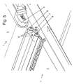
- ein Detailausschnitt aus dem Bereich des Übergangs von einem Förderband zum anderen Förderband mit der erfindungsgemäßen Nachrüsteinheit;
- Fig. 6
- eine alternative Ausführungsform des Förderers mit einer Zwischenleiste zur Überwölbung des Gurtes;
- Fig. 7
- einen altenativen Förderer zum Transportieren von Gegenständen mit abgeschrägtem Förderband.
- Fig. 1
- a conveyor for transporting articles without the retrofit unit according to the invention;
- Fig. 2
- the promoter in
Fig. 1 , but with the retrofit unit according to the invention; - Fig. 3
- a detail from
Fig. 2 ; - Fig. 4
- an individual representation of the retrofit unit;
- Fig. 5
- a detail from the area of the transition from a conveyor belt to the other conveyor belt with the retrofit unit according to the invention;
- Fig. 6
- an alternative embodiment of the conveyor with an intermediate strip for buckling of the belt;
- Fig. 7
- an alternative conveyor for transporting objects with a bevelled conveyor belt.
Der Förderer in seiner Ausgangskonstellation ist in
Für den Nichtgebrauchszustand sind dabei die Förderbänder 1 teleskopartig ineinandergeschoben, wie dies in der Darstellung in
Der Förderer, wie er in
Um dennoch diese umgekehrte Laufrichtung des Förderers einsetzen zu können, ist eine separate Einrichtung vorgesehen, welche im Bereich des Etagenübergangs zwischen zwei benachbarten Förderbändern 1 anbringbar ist. Diese Einrichtung ist in
Diese Zusatzeinrichtung besitzt ein eigenes Gestell 5. Dieses weist seitliche Führungen 6 auf. Weiterhin sind eine Antriebsrolle 7 sowie zwei Rollen 8 vorgesehen. Diese können jeweils mit einer reibungserhöhenden Beschichtung 9 versehen sein.This accessory has its
Das Gestell 5 wird im Übergangsbereich zwischen zwei benachbarten Förderbändern 1 angeordnet und hat den Zweck, die Gesamthöhe zwischen den beiden Etagen durch die Rollen 8 in Teilhöhen zu überwinden, so daß gewissermaßen eine Schräge zwischen den beiden Etagen ausgebildet ist. Zu diesem Zweck liegt die Antriebswelle 7 auf dem Gurt 4 des Förderbandes 1 auf. Durch die Vorwärtsbewegung des Förderbands 1 (in
Dies bedeutet, daß der zu transportierende Gegenstand von dem etagenmäßig unteren Förderband 1 in den Wirkungsbereich der Rollen 8 geschoben wird. Da diese angetrieben sind, sorgen diese für den weiteren Transport des Gegenstandes im Bereich des Übergangs zwischen diesen beiden Etagen, und zwar bis der Gegenstand das Förderband 1 der oberen Etage erreicht hat.This means that the object to be transported is pushed by the floor-level
Eine alternative Weiterentwicklung ist in
Bei dieser Variante ist es nicht unbedingt notwendig, daß die Rollen 8 angetrieben sind, beispielsweise durch die zuvor beschriebene Antriebswelle 7. Dies gilt dann, wenn der zu transportierende Gegenstand entsprechend lang ist und mit seinem hinteren Ende auf dem Gurt 4 aufliegt und vor sich hergeschoben wird, bis er mit seinem vorderen Ende vom nächsten Gurt 4 ergriffen wird.In this variant, it is not absolutely necessary that the
Eine weitere Ausführungsvariante eines Förderers zum Transportieren von Gegenständen zeigt
Die vorbeschriebene und in der Zeichnung dargestellte Abschrägung befindet sich dabei entweder an einem der beiden Enden der Förderbänder 1 oder aber auch alternativ an beiden Enden der Förderbänder 1. Je nachdem, wie die Förderbänder 1 entweder nur in die eine Richtung oder aber in beide Richtungen teleskopierbar sind, sind universell die unterschiedlichsten Transportrichtungen möglich.The bevel described above and shown in the drawing is located either at one of the two ends of the
- 11
- Förderbandconveyor belt
- 22
- Gestellframe
- 33
- Trommeldrum
- 44
- Gurtbelt
- 55
- Gestellframe
- 66
- seitliche Führunglateral guidance
- 77
- Antriebswelledrive shaft
- 88th
- Rollerole
- 99
- Beschichtungcoating
- 1010
- Querleistecleat
- 1111
- UmlenktrommelUmlenktrommel
Claims (13)
mit mehreren Förderbändern (1),
welche jeweils ein eigenes Gestell (2) und einen eigenen, und um endseitige Trommeln (3) endlos umlaufenden Gurt (4) aufweisen,
wobei die Förderbänder (1) im Nichtgebrauchszustand in ihrer Längserstreckung zusammengeschoben sind und
wobei die Förderbänder (1) im Gebrauchszustand teilweise oder vollständig, teleskopartig in Längsrichtung der Förderbänder (1) auseinandergefahren werden können und dabei die Enden benachbarter Förderbänder (1) etagenartig übereinander liegen,
dadurch gekennzeichnet,
daß im Bereich des etagenartigen Übergangs von einem Förderband (1) zum benachbarten Förderband (1) in Transportrichtung gesehen die zu überwindende Gesamthöhe über eine vorgegebene Transportstrecke abgeflacht ist.Conveyor for transporting objects,
with several conveyor belts (1),
each having its own frame (2) and its own, and around end drums (3) endlessly circulating belt (4),
wherein the conveyor belts (1) are pushed together in the non-use state in its longitudinal extent and
wherein the conveyor belts (1) in use can be moved apart partially or completely, telescopically in the longitudinal direction of the conveyor belts (1) and the ends of adjacent conveyor belts (1) are stacked on top of each other,
characterized,
that in the area of the floor-like transition from a conveyor belt (1) to the adjacent conveyor belt (1) seen in the transport direction, the total height to be overcome is flattened over a predetermined transport path.
dadurch gekennzeichnet,
daß im Bereich des etagenartigen Übergangs von einem Förderband (1) zum benachbarten Förderband (1) wenigstens eine in Transportrichtung gesehen querverlaufende Leiste vorgesehen ist, welche die zu überwindende Gesamthöhe in wenigstens eine zu überwindende Teilhöhe unterteilt.Conveyor according to claim 1,
characterized,
that in the region of the floor-like transition from a conveyor belt (1) to the adjacent conveyor belt (1) is provided at least one transverse bar as seen in the transport direction, which divides the total height to be overcome in at least one partial height to be overcome.
dadurch gekennzeichnet,
daß mehrere Leisten vorgesehen sind.Conveyor according to claim 2,
characterized,
that several strips are provided.
dadurch gekennzeichnet,
daß den Leisten in Transportrichtung der Förderbänder (1) gesehen seitliche Führungen (6) zugeordnet sind.Conveyor according to claim 2 or 3,
characterized,
that the strips in the transport direction of the conveyor belts (1) seen side guides (6) are associated.
dadurch gekennzeichnet,
daß die Leiste eine drehbare Rolle (8) ist.Conveyor according to one of claims 2 to 4,
characterized,
that the strip is a rotatable roller (8).
dadurch gekennzeichnet,
daß die Rolle/n (8) frei drehbar ist/sind.Conveyor according to one of claims 2 to 5,
characterized,
that the roller / s (8) is freely rotatable / are.
dadurch gekennzeichnet,
daß die Rolle/n (8) von dem Gurt (4) des Förderbandes (1) angetrieben wird/werden.Conveyor according to one of claims 2 to 5,
characterized,
in that the roller (s) (8) is / are driven by the belt (4) of the conveyor belt (1).
dadurch gekennzeichnet,
daß wenigstens eine Antriebsrolle (7) vorgesehen ist, welche über Reibkontakt von dem Gurt (4) des Förderbands (1) angetrieben wird, und
daß der Antriebswelle (7) wenigstens eine, vorzugsweise zwei Rollen (8) zugeordnet sind, welche über Reibkontakt von der Antriebsrolle (7) angetrieben werden.Conveyor according to claim 7,
characterized,
that at least one drive roller (7) is provided, which is driven by frictional contact of the belt (4) of the conveyor belt (1), and
in that the drive shaft (7) is assigned at least one, preferably two, rollers (8) which are driven via frictional contact by the drive roller (7).
dadurch gekennzeichnet,
daß die Rolle/n (8) und/oder Antriebsrolle (7) mit einer reibungserhöhenden Beschichtung (9) versehen sind.Conveyor according to one of claims 2 to 8,
characterized,
that the roller / s (8) and / or drive roller (7) with a friction-enhancing coating (9) are provided.
dadurch gekennzeichnet,
daß ein separates Gestell (5) für die Rolle/n (8) sowie ggf. Antriebsrolle (7) vorgesehen ist, welches bedarfsweise am Förderer anbringbar ist.Conveyor according to one of claims 2 to 9,
characterized,
in that a separate frame (5) is provided for the roller (s) (8) and optionally the drive roller (7), which can be attached to the conveyor as required.
dadurch gekennzeichnet,
daß in Transportrichtung des Gurtes (4) gesehen vor der Leiste eine Querleiste (10) zwischen dem Gurt (4) und der darunter befindlichen Auflagefläche für diesen Gurt (4) derart angeordnet ist, daß der Gurt (4) die Querleiste (10) überwölbt.Conveyor according to one of claims 2 to 10,
characterized,
that in the transport direction of the belt (4) seen in front of the bar a transverse bar (10) between the belt (4) and the underlying support surface for this belt (4) is arranged such that the belt (4) arched over the transverse bar (10) ,
dadurch gekennzeichnet,
daß im Bereich des etagenartigen Übergangs von einem Förderband (1) zum benachbarten Förderband (1) in Transportrichtung gesehen das Obertrum des oberhalb des darunter befindlichen Förderbandes (1) liegenden oberen Förderbandes (1) zum freien Ende hin zu einem spitzen Winkel als Schräge abgeflacht ist.Conveyor according to claim 1,
characterized,
that in the area of the floor-like transition from a conveyor belt (1) to the adjacent conveyor belt (1) seen in the transport direction, the upper strand of the above underlying conveyor belt (1) lying upper conveyor belt (1) is flattened to the free end to an acute angle as a slope.
Applications Claiming Priority (1)
| Application Number | Priority Date | Filing Date | Title |
|---|---|---|---|
| DE200910018163 DE102009018163B4 (en) | 2009-04-22 | 2009-04-22 | Separate device for a conveyor for transporting objects |
Publications (3)
| Publication Number | Publication Date |
|---|---|
| EP2243728A2 true EP2243728A2 (en) | 2010-10-27 |
| EP2243728A3 EP2243728A3 (en) | 2013-02-20 |
| EP2243728B1 EP2243728B1 (en) | 2013-12-11 |
Family
ID=42231173
Family Applications (1)
| Application Number | Title | Priority Date | Filing Date |
|---|---|---|---|
| EP10003884.3A Active EP2243728B1 (en) | 2009-04-22 | 2010-04-13 | Transporter for transporting objects |
Country Status (2)
| Country | Link |
|---|---|
| EP (1) | EP2243728B1 (en) |
| DE (1) | DE102009018163B4 (en) |
Cited By (10)
| Publication number | Priority date | Publication date | Assignee | Title |
|---|---|---|---|---|
| CN104386419A (en) * | 2014-11-17 | 2015-03-04 | 浙江大学 | Ellipsoidal fruit conveying and rotating device |
| CN104458744A (en) * | 2014-11-17 | 2015-03-25 | 浙江大学 | Device for acquiring full-surface hyperspectral images of spheroidic fruits on line |
| CN104909111A (en) * | 2014-03-11 | 2015-09-16 | 德国邮政股份公司 | System with telescopic conveyor and method therefor |
| CN106044048A (en) * | 2016-07-29 | 2016-10-26 | 芜湖鸣人热能设备有限公司 | Steel plate conveying device |
| CN108033194A (en) * | 2018-01-05 | 2018-05-15 | 苏州双祺自动化设备有限公司 | Weigh Expansion belt conveyor |
| CN108840027A (en) * | 2018-07-27 | 2018-11-20 | 烟台杰瑞石油装备技术有限公司 | A kind of double arch conveyor belts |
| CN109026139A (en) * | 2018-09-19 | 2018-12-18 | 贵州大学 | It is a kind of with prevent mineral slide function mining mineral conveying device |
| CN109132332A (en) * | 2018-09-29 | 2019-01-04 | 佛山市奥楷机械科技有限公司 | A kind of flexible conveying device of sausage hanging rod |
| WO2019120597A1 (en) * | 2017-12-21 | 2019-06-27 | Gawronski Gmbh | Telescopic conveyor |
| CN112320198A (en) * | 2020-11-26 | 2021-02-05 | 广东和胜工业铝材股份有限公司 | Telescopic conveying equipment |
Families Citing this family (3)
| Publication number | Priority date | Publication date | Assignee | Title |
|---|---|---|---|---|
| ES2910704T3 (en) * | 2015-04-23 | 2022-05-13 | Laitram Llc | Input and output assemblies for a conveyor |
| CN105083847B (en) * | 2015-08-03 | 2017-12-01 | 宁波亿普瑞物流自动化分拣设备有限公司 | One kind five saves drawer type transporting equipment |
| CN114435862B (en) * | 2020-11-04 | 2023-10-10 | 深圳顺丰泰森控股(集团)有限公司 | Transmission mechanism, transmission device and sorting transmission line |
Family Cites Families (10)
| Publication number | Priority date | Publication date | Assignee | Title |
|---|---|---|---|---|
| US2760617A (en) * | 1955-01-11 | 1956-08-28 | Mathews Conveyer Co | Telescoping conveyer |
| JPS58161916U (en) * | 1982-04-20 | 1983-10-28 | 株式会社中村機器エンジニアリング | Transfer device between conveyors |
| ATE128435T1 (en) * | 1990-06-20 | 1995-10-15 | Digitron Ag | METHOD AND DEVICE FOR RECORDING OR DISPOSAL OF PACKAGE-SHAPED GOODS. |
| US6481563B1 (en) * | 1999-12-29 | 2002-11-19 | Rapistan Systems Advertising Corp. | Extendable conveyor with additional boom section |
| JP2002087557A (en) * | 2000-09-19 | 2002-03-27 | Kamusa Shoji:Kk | Conveyer device for transferring small fish |
| DE10255843B4 (en) * | 2002-11-29 | 2012-06-06 | Caljan Rite-Hite Aps | Telescopic conveyor |
| DE102006008583B3 (en) * | 2006-02-24 | 2007-08-09 | Gawronski Industrievertretungen Gmbh | Conveyor for transporting articles, has multiple conveyor belts, which have individual frame and individual belt continuously rotating around end-side drums |
| US7416075B2 (en) * | 2006-08-08 | 2008-08-26 | Northstar Industries, Inc. | Telescoping conveyor with powered and steerable discharge section |
| DE202006015281U1 (en) * | 2006-10-04 | 2007-03-08 | Msk-Verpackungs-Systeme Gmbh | Device for raising layer consisting of number of containers, e.g. for use in glass industry, has transport surface that can be guided under the containers of row A |
| FR2911332B1 (en) * | 2007-01-11 | 2009-11-27 | Advanced Automation | CONVEYOR FOR REMOVAL OF PRODUCTS, IN PARTICULAR FOODSTUFFS ON A PLANT |
-
2009
- 2009-04-22 DE DE200910018163 patent/DE102009018163B4/en active Active
-
2010
- 2010-04-13 EP EP10003884.3A patent/EP2243728B1/en active Active
Non-Patent Citations (1)
| Title |
|---|
| None |
Cited By (15)
| Publication number | Priority date | Publication date | Assignee | Title |
|---|---|---|---|---|
| CN104909111A (en) * | 2014-03-11 | 2015-09-16 | 德国邮政股份公司 | System with telescopic conveyor and method therefor |
| US9776801B2 (en) | 2014-03-11 | 2017-10-03 | Deutsche Post Ag | System with telescopic conveyor and method therefor |
| CN104458744A (en) * | 2014-11-17 | 2015-03-25 | 浙江大学 | Device for acquiring full-surface hyperspectral images of spheroidic fruits on line |
| CN104458744B (en) * | 2014-11-17 | 2017-05-03 | 浙江大学 | Device for acquiring full-surface hyperspectral images of spheroidic fruits on line |
| CN104386419A (en) * | 2014-11-17 | 2015-03-04 | 浙江大学 | Ellipsoidal fruit conveying and rotating device |
| CN106044048A (en) * | 2016-07-29 | 2016-10-26 | 芜湖鸣人热能设备有限公司 | Steel plate conveying device |
| WO2019120597A1 (en) * | 2017-12-21 | 2019-06-27 | Gawronski Gmbh | Telescopic conveyor |
| US10899548B2 (en) | 2017-12-21 | 2021-01-26 | Gawronski Gmbh | Telescopic conveyor |
| CN108033194A (en) * | 2018-01-05 | 2018-05-15 | 苏州双祺自动化设备有限公司 | Weigh Expansion belt conveyor |
| CN108840027A (en) * | 2018-07-27 | 2018-11-20 | 烟台杰瑞石油装备技术有限公司 | A kind of double arch conveyor belts |
| CN109026139A (en) * | 2018-09-19 | 2018-12-18 | 贵州大学 | It is a kind of with prevent mineral slide function mining mineral conveying device |
| CN109132332A (en) * | 2018-09-29 | 2019-01-04 | 佛山市奥楷机械科技有限公司 | A kind of flexible conveying device of sausage hanging rod |
| CN109132332B (en) * | 2018-09-29 | 2024-05-28 | 佛山市奥楷机械科技有限公司 | Sausage peg flexible conveyor |
| CN112320198A (en) * | 2020-11-26 | 2021-02-05 | 广东和胜工业铝材股份有限公司 | Telescopic conveying equipment |
| CN112320198B (en) * | 2020-11-26 | 2024-06-04 | 广东和胜工业铝材股份有限公司 | Telescopic conveying equipment |
Also Published As
| Publication number | Publication date |
|---|---|
| DE102009018163B4 (en) | 2011-03-24 |
| DE102009018163A1 (en) | 2010-12-30 |
| EP2243728B1 (en) | 2013-12-11 |
| EP2243728A3 (en) | 2013-02-20 |
Similar Documents
| Publication | Publication Date | Title |
|---|---|---|
| DE102009018163B4 (en) | Separate device for a conveyor for transporting objects | |
| EP3078543B1 (en) | Vehicle for the transport of bulk and/or piece goods | |
| EP1189825B1 (en) | Conveying and/or storage device for packaged goods | |
| EP1826154A1 (en) | Conveyor belt for transporting articles | |
| CH701686A1 (en) | Supporting device for conveying heavy loads. | |
| WO2010135756A1 (en) | Order picking device | |
| EP1283809B1 (en) | Device for conveying a supply roll | |
| DE2853483A1 (en) | JAM FEEDER FOR PIECE | |
| EP0541850A1 (en) | Curvilinear plate conveyor | |
| DE1951598B2 (en) | Evade lane for production lines containing a work device | |
| DE2233832A1 (en) | DEVICE FOR TRANSPORTING LOADS | |
| DE4427477A1 (en) | Conveying apparatus | |
| EP2754626B1 (en) | Conveyor device with concave belt | |
| DE19912391A1 (en) | Roller conveyor or roller conveyor section | |
| DE1531831B2 (en) | CONVEYOR DEVICE WITH PRESSURELESS STORAGE | |
| DE2621304C2 (en) | Collecting device, preferably for elongated objects | |
| EP0949166A1 (en) | Method for a continuous lining-up of containers, successively delivered at a pick-up section | |
| EP3081448B1 (en) | Station for an aerial cableway with transport device and roof structure | |
| DE2110819A1 (en) | Conveyor device with at least one conveyor chain | |
| DE3233271C2 (en) | Conveyor device for piece goods | |
| DE4111087C1 (en) | Displacement table for goods transported on roller track - has axis supported conveyor rollers, longitudinally movable for transverse goods displacement | |
| WO2001036302A1 (en) | Picking store for piece goods | |
| EP2507149B1 (en) | Conveying system for piece goods | |
| DE20018272U1 (en) | Belt conveyor for general cargo | |
| DE1277129B (en) | Conveyor device for objects, especially eggs |
Legal Events
| Date | Code | Title | Description |
|---|---|---|---|
| PUAI | Public reference made under article 153(3) epc to a published international application that has entered the european phase |
Free format text: ORIGINAL CODE: 0009012 |
|
| AK | Designated contracting states |
Kind code of ref document: A2 Designated state(s): AT BE BG CH CY CZ DE DK EE ES FI FR GB GR HR HU IE IS IT LI LT LU LV MC MK MT NL NO PL PT RO SE SI SK SM TR |
|
| AX | Request for extension of the european patent |
Extension state: AL BA ME RS |
|
| PUAL | Search report despatched |
Free format text: ORIGINAL CODE: 0009013 |
|
| AK | Designated contracting states |
Kind code of ref document: A3 Designated state(s): AT BE BG CH CY CZ DE DK EE ES FI FR GB GR HR HU IE IS IT LI LT LU LV MC MK MT NL NO PL PT RO SE SI SK SM TR |
|
| AX | Request for extension of the european patent |
Extension state: AL BA ME RS |
|
| RIC1 | Information provided on ipc code assigned before grant |
Ipc: B65G 21/14 20060101ALI20130115BHEP Ipc: B65G 15/26 20060101ALI20130115BHEP Ipc: B65G 13/071 20060101AFI20130115BHEP Ipc: B65G 47/66 20060101ALI20130115BHEP |
|
| 17P | Request for examination filed |
Effective date: 20130726 |
|
| RBV | Designated contracting states (corrected) |
Designated state(s): AT BE BG CH CY CZ DE DK EE ES FI FR GB GR HR HU IE IS IT LI LT LU LV MC MK MT NL NO PL PT RO SE SI SK SM TR |
|
| GRAP | Despatch of communication of intention to grant a patent |
Free format text: ORIGINAL CODE: EPIDOSNIGR1 |
|
| INTG | Intention to grant announced |
Effective date: 20130918 |
|
| GRAS | Grant fee paid |
Free format text: ORIGINAL CODE: EPIDOSNIGR3 |
|
| GRAA | (expected) grant |
Free format text: ORIGINAL CODE: 0009210 |
|
| AK | Designated contracting states |
Kind code of ref document: B1 Designated state(s): AT BE BG CH CY CZ DE DK EE ES FI FR GB GR HR HU IE IS IT LI LT LU LV MC MK MT NL NO PL PT RO SE SI SK SM TR |
|
| REG | Reference to a national code |
Ref country code: GB Ref legal event code: FG4D Free format text: NOT ENGLISH |
|
| REG | Reference to a national code |
Ref country code: CH Ref legal event code: EP |
|
| REG | Reference to a national code |
Ref country code: AT Ref legal event code: REF Ref document number: 644451 Country of ref document: AT Kind code of ref document: T Effective date: 20140115 |
|
| REG | Reference to a national code |
Ref country code: IE Ref legal event code: FG4D Free format text: LANGUAGE OF EP DOCUMENT: GERMAN |
|
| REG | Reference to a national code |
Ref country code: DE Ref legal event code: R096 Ref document number: 502010005584 Country of ref document: DE Effective date: 20140206 |
|
| REG | Reference to a national code |
Ref country code: NL Ref legal event code: T3 |
|
| REG | Reference to a national code |
Ref country code: SE Ref legal event code: TRGR |
|
| PG25 | Lapsed in a contracting state [announced via postgrant information from national office to epo] |
Ref country code: HR Free format text: LAPSE BECAUSE OF FAILURE TO SUBMIT A TRANSLATION OF THE DESCRIPTION OR TO PAY THE FEE WITHIN THE PRESCRIBED TIME-LIMIT Effective date: 20131211 Ref country code: FI Free format text: LAPSE BECAUSE OF FAILURE TO SUBMIT A TRANSLATION OF THE DESCRIPTION OR TO PAY THE FEE WITHIN THE PRESCRIBED TIME-LIMIT Effective date: 20131211 Ref country code: NO Free format text: LAPSE BECAUSE OF FAILURE TO SUBMIT A TRANSLATION OF THE DESCRIPTION OR TO PAY THE FEE WITHIN THE PRESCRIBED TIME-LIMIT Effective date: 20140311 Ref country code: LT Free format text: LAPSE BECAUSE OF FAILURE TO SUBMIT A TRANSLATION OF THE DESCRIPTION OR TO PAY THE FEE WITHIN THE PRESCRIBED TIME-LIMIT Effective date: 20131211 |
|
| REG | Reference to a national code |
Ref country code: LT Ref legal event code: MG4D |
|
| PG25 | Lapsed in a contracting state [announced via postgrant information from national office to epo] |
Ref country code: CY Free format text: LAPSE BECAUSE OF FAILURE TO SUBMIT A TRANSLATION OF THE DESCRIPTION OR TO PAY THE FEE WITHIN THE PRESCRIBED TIME-LIMIT Effective date: 20131211 Ref country code: LV Free format text: LAPSE BECAUSE OF FAILURE TO SUBMIT A TRANSLATION OF THE DESCRIPTION OR TO PAY THE FEE WITHIN THE PRESCRIBED TIME-LIMIT Effective date: 20131211 |
|
| PG25 | Lapsed in a contracting state [announced via postgrant information from national office to epo] |
Ref country code: IS Free format text: LAPSE BECAUSE OF FAILURE TO SUBMIT A TRANSLATION OF THE DESCRIPTION OR TO PAY THE FEE WITHIN THE PRESCRIBED TIME-LIMIT Effective date: 20140411 Ref country code: EE Free format text: LAPSE BECAUSE OF FAILURE TO SUBMIT A TRANSLATION OF THE DESCRIPTION OR TO PAY THE FEE WITHIN THE PRESCRIBED TIME-LIMIT Effective date: 20131211 |
|
| PG25 | Lapsed in a contracting state [announced via postgrant information from national office to epo] |
Ref country code: ES Free format text: LAPSE BECAUSE OF FAILURE TO SUBMIT A TRANSLATION OF THE DESCRIPTION OR TO PAY THE FEE WITHIN THE PRESCRIBED TIME-LIMIT Effective date: 20131211 Ref country code: SK Free format text: LAPSE BECAUSE OF FAILURE TO SUBMIT A TRANSLATION OF THE DESCRIPTION OR TO PAY THE FEE WITHIN THE PRESCRIBED TIME-LIMIT Effective date: 20131211 Ref country code: PL Free format text: LAPSE BECAUSE OF FAILURE TO SUBMIT A TRANSLATION OF THE DESCRIPTION OR TO PAY THE FEE WITHIN THE PRESCRIBED TIME-LIMIT Effective date: 20131211 Ref country code: CZ Free format text: LAPSE BECAUSE OF FAILURE TO SUBMIT A TRANSLATION OF THE DESCRIPTION OR TO PAY THE FEE WITHIN THE PRESCRIBED TIME-LIMIT Effective date: 20131211 Ref country code: RO Free format text: LAPSE BECAUSE OF FAILURE TO SUBMIT A TRANSLATION OF THE DESCRIPTION OR TO PAY THE FEE WITHIN THE PRESCRIBED TIME-LIMIT Effective date: 20131211 Ref country code: PT Free format text: LAPSE BECAUSE OF FAILURE TO SUBMIT A TRANSLATION OF THE DESCRIPTION OR TO PAY THE FEE WITHIN THE PRESCRIBED TIME-LIMIT Effective date: 20140411 |
|
| REG | Reference to a national code |
Ref country code: DE Ref legal event code: R097 Ref document number: 502010005584 Country of ref document: DE |
|
| PLBE | No opposition filed within time limit |
Free format text: ORIGINAL CODE: 0009261 |
|
| STAA | Information on the status of an ep patent application or granted ep patent |
Free format text: STATUS: NO OPPOSITION FILED WITHIN TIME LIMIT |
|
| PG25 | Lapsed in a contracting state [announced via postgrant information from national office to epo] |
Ref country code: DK Free format text: LAPSE BECAUSE OF FAILURE TO SUBMIT A TRANSLATION OF THE DESCRIPTION OR TO PAY THE FEE WITHIN THE PRESCRIBED TIME-LIMIT Effective date: 20131211 |
|
| 26N | No opposition filed |
Effective date: 20140912 |
|
| PG25 | Lapsed in a contracting state [announced via postgrant information from national office to epo] |
Ref country code: MC Free format text: LAPSE BECAUSE OF FAILURE TO SUBMIT A TRANSLATION OF THE DESCRIPTION OR TO PAY THE FEE WITHIN THE PRESCRIBED TIME-LIMIT Effective date: 20131211 Ref country code: LU Free format text: LAPSE BECAUSE OF FAILURE TO SUBMIT A TRANSLATION OF THE DESCRIPTION OR TO PAY THE FEE WITHIN THE PRESCRIBED TIME-LIMIT Effective date: 20140413 |
|
| REG | Reference to a national code |
Ref country code: CH Ref legal event code: PL |
|
| REG | Reference to a national code |
Ref country code: DE Ref legal event code: R097 Ref document number: 502010005584 Country of ref document: DE Effective date: 20140912 |
|
| REG | Reference to a national code |
Ref country code: IE Ref legal event code: MM4A |
|
| PG25 | Lapsed in a contracting state [announced via postgrant information from national office to epo] |
Ref country code: LI Free format text: LAPSE BECAUSE OF NON-PAYMENT OF DUE FEES Effective date: 20140430 Ref country code: CH Free format text: LAPSE BECAUSE OF NON-PAYMENT OF DUE FEES Effective date: 20140430 |
|
| PG25 | Lapsed in a contracting state [announced via postgrant information from national office to epo] |
Ref country code: SI Free format text: LAPSE BECAUSE OF FAILURE TO SUBMIT A TRANSLATION OF THE DESCRIPTION OR TO PAY THE FEE WITHIN THE PRESCRIBED TIME-LIMIT Effective date: 20131211 |
|
| PG25 | Lapsed in a contracting state [announced via postgrant information from national office to epo] |
Ref country code: IE Free format text: LAPSE BECAUSE OF NON-PAYMENT OF DUE FEES Effective date: 20140413 |
|
| PG25 | Lapsed in a contracting state [announced via postgrant information from national office to epo] |
Ref country code: MT Free format text: LAPSE BECAUSE OF FAILURE TO SUBMIT A TRANSLATION OF THE DESCRIPTION OR TO PAY THE FEE WITHIN THE PRESCRIBED TIME-LIMIT Effective date: 20131211 |
|
| REG | Reference to a national code |
Ref country code: FR Ref legal event code: PLFP Year of fee payment: 7 |
|
| PG25 | Lapsed in a contracting state [announced via postgrant information from national office to epo] |
Ref country code: SM Free format text: LAPSE BECAUSE OF FAILURE TO SUBMIT A TRANSLATION OF THE DESCRIPTION OR TO PAY THE FEE WITHIN THE PRESCRIBED TIME-LIMIT Effective date: 20131211 |
|
| REG | Reference to a national code |
Ref country code: AT Ref legal event code: MM01 Ref document number: 644451 Country of ref document: AT Kind code of ref document: T Effective date: 20150413 |
|
| PG25 | Lapsed in a contracting state [announced via postgrant information from national office to epo] |
Ref country code: IT Free format text: LAPSE BECAUSE OF FAILURE TO SUBMIT A TRANSLATION OF THE DESCRIPTION OR TO PAY THE FEE WITHIN THE PRESCRIBED TIME-LIMIT Effective date: 20131211 Ref country code: GR Free format text: LAPSE BECAUSE OF FAILURE TO SUBMIT A TRANSLATION OF THE DESCRIPTION OR TO PAY THE FEE WITHIN THE PRESCRIBED TIME-LIMIT Effective date: 20140312 Ref country code: BG Free format text: LAPSE BECAUSE OF FAILURE TO SUBMIT A TRANSLATION OF THE DESCRIPTION OR TO PAY THE FEE WITHIN THE PRESCRIBED TIME-LIMIT Effective date: 20131211 |
|
| PG25 | Lapsed in a contracting state [announced via postgrant information from national office to epo] |
Ref country code: HU Free format text: LAPSE BECAUSE OF FAILURE TO SUBMIT A TRANSLATION OF THE DESCRIPTION OR TO PAY THE FEE WITHIN THE PRESCRIBED TIME-LIMIT; INVALID AB INITIO Effective date: 20100413 Ref country code: TR Free format text: LAPSE BECAUSE OF FAILURE TO SUBMIT A TRANSLATION OF THE DESCRIPTION OR TO PAY THE FEE WITHIN THE PRESCRIBED TIME-LIMIT Effective date: 20131211 Ref country code: BE Free format text: LAPSE BECAUSE OF FAILURE TO SUBMIT A TRANSLATION OF THE DESCRIPTION OR TO PAY THE FEE WITHIN THE PRESCRIBED TIME-LIMIT Effective date: 20140430 |
|
| PG25 | Lapsed in a contracting state [announced via postgrant information from national office to epo] |
Ref country code: AT Free format text: LAPSE BECAUSE OF NON-PAYMENT OF DUE FEES Effective date: 20150413 |
|
| REG | Reference to a national code |
Ref country code: FR Ref legal event code: PLFP Year of fee payment: 8 |
|
| REG | Reference to a national code |
Ref country code: FR Ref legal event code: PLFP Year of fee payment: 9 |
|
| PG25 | Lapsed in a contracting state [announced via postgrant information from national office to epo] |
Ref country code: MK Free format text: LAPSE BECAUSE OF FAILURE TO SUBMIT A TRANSLATION OF THE DESCRIPTION OR TO PAY THE FEE WITHIN THE PRESCRIBED TIME-LIMIT Effective date: 20131211 |
|
| REG | Reference to a national code |
Ref country code: DE Ref legal event code: R082 Ref document number: 502010005584 Country of ref document: DE Representative=s name: STUMPF PATENTANWAELTE PARTGMBB, DE Ref country code: DE Ref legal event code: R082 Ref document number: 502010005584 Country of ref document: DE |
|
| REG | Reference to a national code |
Ref country code: DE Ref legal event code: R082 Ref document number: 502010005584 Country of ref document: DE Representative=s name: STUMPF PATENTANWAELTE PARTGMBB, DE |
|
| PGFP | Annual fee paid to national office [announced via postgrant information from national office to epo] |
Ref country code: NL Payment date: 20240422 Year of fee payment: 15 |
|
| PGFP | Annual fee paid to national office [announced via postgrant information from national office to epo] |
Ref country code: GB Payment date: 20240423 Year of fee payment: 15 |
|
| PGFP | Annual fee paid to national office [announced via postgrant information from national office to epo] |
Ref country code: DE Payment date: 20240325 Year of fee payment: 15 |
|
| PGFP | Annual fee paid to national office [announced via postgrant information from national office to epo] |
Ref country code: FR Payment date: 20240423 Year of fee payment: 15 |
|
| PGFP | Annual fee paid to national office [announced via postgrant information from national office to epo] |
Ref country code: SE Payment date: 20240423 Year of fee payment: 15 |