EP2243655A1 - Device with additional restoring force on the gas pedal based on the deviation of a vehicle paramenter from the set value - Google Patents
Device with additional restoring force on the gas pedal based on the deviation of a vehicle paramenter from the set value Download PDFInfo
- Publication number
- EP2243655A1 EP2243655A1 EP10166107A EP10166107A EP2243655A1 EP 2243655 A1 EP2243655 A1 EP 2243655A1 EP 10166107 A EP10166107 A EP 10166107A EP 10166107 A EP10166107 A EP 10166107A EP 2243655 A1 EP2243655 A1 EP 2243655A1
- Authority
- EP
- European Patent Office
- Prior art keywords
- force
- pedal
- stop
- speed
- spring
- Prior art date
- Legal status (The legal status is an assumption and is not a legal conclusion. Google has not performed a legal analysis and makes no representation as to the accuracy of the status listed.)
- Granted
Links
- 230000001419 dependent effect Effects 0.000 claims abstract description 7
- 230000008859 change Effects 0.000 claims description 4
- 230000001960 triggered effect Effects 0.000 claims description 3
- 238000004804 winding Methods 0.000 claims description 3
- 230000004044 response Effects 0.000 claims description 2
- 230000003247 decreasing effect Effects 0.000 claims 1
- 230000006870 function Effects 0.000 description 27
- 230000005540 biological transmission Effects 0.000 description 17
- 230000008901 benefit Effects 0.000 description 10
- 230000008878 coupling Effects 0.000 description 9
- 238000010168 coupling process Methods 0.000 description 9
- 238000005859 coupling reaction Methods 0.000 description 9
- 238000010276 construction Methods 0.000 description 8
- 238000012546 transfer Methods 0.000 description 8
- 238000000034 method Methods 0.000 description 6
- 230000008569 process Effects 0.000 description 6
- 238000006243 chemical reaction Methods 0.000 description 4
- 230000000694 effects Effects 0.000 description 4
- 230000007257 malfunction Effects 0.000 description 3
- 239000000725 suspension Substances 0.000 description 3
- 230000009471 action Effects 0.000 description 2
- 238000013459 approach Methods 0.000 description 2
- 230000001276 controlling effect Effects 0.000 description 2
- 230000002401 inhibitory effect Effects 0.000 description 2
- 230000004048 modification Effects 0.000 description 2
- 238000012986 modification Methods 0.000 description 2
- 230000001105 regulatory effect Effects 0.000 description 2
- 229910000831 Steel Inorganic materials 0.000 description 1
- 230000001133 acceleration Effects 0.000 description 1
- 230000004913 activation Effects 0.000 description 1
- 238000011109 contamination Methods 0.000 description 1
- 230000000881 depressing effect Effects 0.000 description 1
- 238000013461 design Methods 0.000 description 1
- 239000000446 fuel Substances 0.000 description 1
- 230000008571 general function Effects 0.000 description 1
- 230000006872 improvement Effects 0.000 description 1
- 238000003780 insertion Methods 0.000 description 1
- 230000037431 insertion Effects 0.000 description 1
- 238000004519 manufacturing process Methods 0.000 description 1
- KJFBVJALEQWJBS-XUXIUFHCSA-N maribavir Chemical compound CC(C)NC1=NC2=CC(Cl)=C(Cl)C=C2N1[C@H]1O[C@@H](CO)[C@H](O)[C@@H]1O KJFBVJALEQWJBS-XUXIUFHCSA-N 0.000 description 1
- 239000000463 material Substances 0.000 description 1
- 230000007246 mechanism Effects 0.000 description 1
- 238000012544 monitoring process Methods 0.000 description 1
- 230000036316 preload Effects 0.000 description 1
- 238000003825 pressing Methods 0.000 description 1
- 230000035484 reaction time Effects 0.000 description 1
- 230000009467 reduction Effects 0.000 description 1
- 238000004904 shortening Methods 0.000 description 1
- 239000010959 steel Substances 0.000 description 1
- 238000003860 storage Methods 0.000 description 1
Images


Classifications
-
- G—PHYSICS
- G05—CONTROLLING; REGULATING
- G05G—CONTROL DEVICES OR SYSTEMS INSOFAR AS CHARACTERISED BY MECHANICAL FEATURES ONLY
- G05G1/00—Controlling members, e.g. knobs or handles; Assemblies or arrangements thereof; Indicating position of controlling members
- G05G1/30—Controlling members actuated by foot
-
- B—PERFORMING OPERATIONS; TRANSPORTING
- B60—VEHICLES IN GENERAL
- B60K—ARRANGEMENT OR MOUNTING OF PROPULSION UNITS OR OF TRANSMISSIONS IN VEHICLES; ARRANGEMENT OR MOUNTING OF PLURAL DIVERSE PRIME-MOVERS IN VEHICLES; AUXILIARY DRIVES FOR VEHICLES; INSTRUMENTATION OR DASHBOARDS FOR VEHICLES; ARRANGEMENTS IN CONNECTION WITH COOLING, AIR INTAKE, GAS EXHAUST OR FUEL SUPPLY OF PROPULSION UNITS IN VEHICLES
- B60K26/00—Arrangements or mounting of propulsion unit control devices in vehicles
- B60K26/02—Arrangements or mounting of propulsion unit control devices in vehicles of initiating means or elements
- B60K26/021—Arrangements or mounting of propulsion unit control devices in vehicles of initiating means or elements with means for providing feel, e.g. by changing pedal force characteristics
-
- B—PERFORMING OPERATIONS; TRANSPORTING
- B60—VEHICLES IN GENERAL
- B60K—ARRANGEMENT OR MOUNTING OF PROPULSION UNITS OR OF TRANSMISSIONS IN VEHICLES; ARRANGEMENT OR MOUNTING OF PLURAL DIVERSE PRIME-MOVERS IN VEHICLES; AUXILIARY DRIVES FOR VEHICLES; INSTRUMENTATION OR DASHBOARDS FOR VEHICLES; ARRANGEMENTS IN CONNECTION WITH COOLING, AIR INTAKE, GAS EXHAUST OR FUEL SUPPLY OF PROPULSION UNITS IN VEHICLES
- B60K31/00—Vehicle fittings, acting on a single sub-unit only, for automatically controlling vehicle speed, i.e. preventing speed from exceeding an arbitrarily established velocity or maintaining speed at a particular velocity, as selected by the vehicle operator
- B60K31/02—Vehicle fittings, acting on a single sub-unit only, for automatically controlling vehicle speed, i.e. preventing speed from exceeding an arbitrarily established velocity or maintaining speed at a particular velocity, as selected by the vehicle operator including electrically actuated servomechanism including an electric control system or a servomechanism in which the vehicle velocity affecting element is actuated electrically
- B60K31/04—Vehicle fittings, acting on a single sub-unit only, for automatically controlling vehicle speed, i.e. preventing speed from exceeding an arbitrarily established velocity or maintaining speed at a particular velocity, as selected by the vehicle operator including electrically actuated servomechanism including an electric control system or a servomechanism in which the vehicle velocity affecting element is actuated electrically and means for comparing one electrical quantity, e.g. voltage, pulse, waveform, flux, or the like, with another quantity of a like kind, which comparison means is involved in the development of an electrical signal which is fed into the controlling means
-
- B—PERFORMING OPERATIONS; TRANSPORTING
- B60—VEHICLES IN GENERAL
- B60K—ARRANGEMENT OR MOUNTING OF PROPULSION UNITS OR OF TRANSMISSIONS IN VEHICLES; ARRANGEMENT OR MOUNTING OF PLURAL DIVERSE PRIME-MOVERS IN VEHICLES; AUXILIARY DRIVES FOR VEHICLES; INSTRUMENTATION OR DASHBOARDS FOR VEHICLES; ARRANGEMENTS IN CONNECTION WITH COOLING, AIR INTAKE, GAS EXHAUST OR FUEL SUPPLY OF PROPULSION UNITS IN VEHICLES
- B60K31/00—Vehicle fittings, acting on a single sub-unit only, for automatically controlling vehicle speed, i.e. preventing speed from exceeding an arbitrarily established velocity or maintaining speed at a particular velocity, as selected by the vehicle operator
- B60K31/18—Vehicle fittings, acting on a single sub-unit only, for automatically controlling vehicle speed, i.e. preventing speed from exceeding an arbitrarily established velocity or maintaining speed at a particular velocity, as selected by the vehicle operator including a device to audibly, visibly, or otherwise signal the existence of unusual or unintended speed to the driver of the vehicle
-
- B—PERFORMING OPERATIONS; TRANSPORTING
- B60—VEHICLES IN GENERAL
- B60T—VEHICLE BRAKE CONTROL SYSTEMS OR PARTS THEREOF; BRAKE CONTROL SYSTEMS OR PARTS THEREOF, IN GENERAL; ARRANGEMENT OF BRAKING ELEMENTS ON VEHICLES IN GENERAL; PORTABLE DEVICES FOR PREVENTING UNWANTED MOVEMENT OF VEHICLES; VEHICLE MODIFICATIONS TO FACILITATE COOLING OF BRAKES
- B60T7/00—Brake-action initiating means
- B60T7/02—Brake-action initiating means for personal initiation
- B60T7/04—Brake-action initiating means for personal initiation foot actuated
- B60T7/042—Brake-action initiating means for personal initiation foot actuated by electrical means, e.g. using travel or force sensors
-
- G—PHYSICS
- G05—CONTROLLING; REGULATING
- G05G—CONTROL DEVICES OR SYSTEMS INSOFAR AS CHARACTERISED BY MECHANICAL FEATURES ONLY
- G05G5/00—Means for preventing, limiting or returning the movements of parts of a control mechanism, e.g. locking controlling member
- G05G5/03—Means for enhancing the operator's awareness of arrival of the controlling member at a command or datum position; Providing feel, e.g. means for creating a counterforce
-
- F—MECHANICAL ENGINEERING; LIGHTING; HEATING; WEAPONS; BLASTING
- F02—COMBUSTION ENGINES; HOT-GAS OR COMBUSTION-PRODUCT ENGINE PLANTS
- F02D—CONTROLLING COMBUSTION ENGINES
- F02D11/00—Arrangements for, or adaptations to, non-automatic engine control initiation means, e.g. operator initiated
- F02D11/06—Arrangements for, or adaptations to, non-automatic engine control initiation means, e.g. operator initiated characterised by non-mechanical control linkages, e.g. fluid control linkages or by control linkages with power drive or assistance
- F02D11/10—Arrangements for, or adaptations to, non-automatic engine control initiation means, e.g. operator initiated characterised by non-mechanical control linkages, e.g. fluid control linkages or by control linkages with power drive or assistance of the electric type
- F02D11/105—Arrangements for, or adaptations to, non-automatic engine control initiation means, e.g. operator initiated characterised by non-mechanical control linkages, e.g. fluid control linkages or by control linkages with power drive or assistance of the electric type characterised by the function converting demand to actuation, e.g. a map indicating relations between an accelerator pedal position and throttle valve opening or target engine torque
Definitions
- the invention relates to a device according to the preamble of patent claim 1.
- the invention relates to a device for controlling a parameter of a motor vehicle (for example, the speed of a vehicle) which has a designed as a pedal control member.
- a parameter of a motor vehicle for example, the speed of a vehicle
- the gas pedal or brake pedal
- the control member in the supply of fuel to the engine and thus the driving speed of the vehicle (or reduces the speed of the activation of the braking system).
- the observance of a suitable and / or prescribed speed is very important.
- the driver In order to recognize the instantaneous speed of a vehicle, the driver must read off the readings on a speedometer with the known displays. During the time in which the driver reads this measuring instrument and assesses the result, he is only partially able to pay attention to the traffic.
- warning displays should be as conspicuous and easily interpretable as possible, for example, in terms of too high a speed, so that the driver can react to it very quickly and without errors.
- the reaction time a display is the shorter, the more compatible it is with the associated control, that is, the higher the apparent relationship between the display and the control itself.
- the presetting is done by means of a rotatable plate.
- the is-speed is represented by a pointer. If the actual speed exceeds the desired speed, a contact is switched by the pointer and a relay switches on a motor, which moves a slide against a stop by means of a rod until the actual speed is sufficiently below the desired speed and so that the engine is switched off. From the previously known control is also known, the force is generated by an electromechanical actuator.
- the invention is therefore based on a device as it results from the preamble of the main claim.
- the object of the invention is to describe improvements of the known constructions, by which the manufacturing costs for the device are reduced, the reliability of the operation of the device is improved and additionally advantageous features are introduced, which simplify the handling of the device in practice. Details of the problem of the known devices can also be taken from the figures 8a and 8c in connection with in the accompanying description.
- the object of the invention is also to ensure the possibility that the generic device can be violated even if the known violation means are blocked.
- FFP function restoring force
- the actuator is controlled by an actuating signal which is triggered by the deviation of a measured variable of the vehicle from a desired value, in particular the driving speed of a predetermined desired speed or braking force of an allowable braking force, or at least dependent and that the force in Dependence on the deviation of the setpoint, in particular the speed of the target speed acts on the control member and that emergency means are provided which allow a trespassing of the pedal against the force even if the Mattertretstoff have a blockage.
- the actuator is provided with a gear via which it outputs the actuating force to the pedal, wherein the gear is a ball-threaded drive, which is formed by a threaded spindle and a threaded nut.
- the threaded spindle acts directly on the pedal and the threaded spindle or the threaded nut is elastically supported in the axial direction by a Kochtretfeder.
- the additional actuating force (ie the FF function) is provided by an electromechanical actuator.
- This actuator is advantageously controllable depending on a number of parameters. This can be done for example by a suitable electronic circuit such as by a processor. In this way it is possible not only the power depending on the size of the deviation of the is-speed of the target speed. Rather, it can also be taken into account with which force the driver is currently operating the gas pedal, so that the actuating force can be adjusted depending on this. In this way, it can be avoided that the driver, for example, in a mountain driving, in which the pedal must be operated with greater force, with little speed exceeding the onset of relatively small actuating force does not feel.
- the force should be qualitatively dependent on the difference in the speeds but not quantitatively of this difference. In other words, even with a small deviation of the actual speed from the target speed, the actuating force should be of sufficient magnitude to allow the driver to feel that the target speed has now been exceeded and the pedal is reset by the actuator.
- the additional force including without this predetermined restoring force can be exceeded by the driver.
- the driver does not yield the actuating force exerted by the actuator, in particular electric motor, the pedal restores force but withstands this force and thus the pedal remains in position or even that the driver exerts a greater force by which the pedal against the force in the Deeper down in the sense of a higher speed.
- the pedal restores force but withstands this force and thus the pedal remains in position or even that the driver exerts a greater force by which the pedal against the force in the Deeper down in the sense of a higher speed.
- the electric motor can be reversed, so can be moved against its drive direction, so can the "trespassing" in a simple manner allow the drive is overcome by a correspondingly high pedal force and the motor in this way practically is forced to turn backwards a bit.
- an elastic member must be inserted in the force path, in order to allow the trespassing, which yields with a sufficiently large force exerted on the pedal and thus allows the pedal to depress against the actuating force.
- the elastic member for example steel spring, must have a sufficiently large preload, otherwise the spring will yield without exerting a greater force on the pedal and so the driver is not warned by the response of the Force Feedback Pedal (FFP) device.
- FFP Force Feedback Pedal
- it is desirable that the spring constant of the spring is small so that the force does not change too much with the position of the pedal.
- the actuating force starts suddenly.
- the control force should not occur creeping, so that the driver hardly realizes that the additional force (FFP force) has deployed and may be subject to the deception that pedal feel has changed. Rather, it is desirable that the additional actuating force starts jerkily and does not leave the driver in doubt about the fact that the control wants to put the pedal back against the operating force of the driver. As a result, the necessary alarm effect can be achieved.
- the means for crossing the pedal against the FFP force can be that the force source providing the additional actuating force can be forced to move counter to its drive direction by a correspondingly high actuating force on the pedals , If, for example, the power source consists of an electric motor, a violation may exist therein; that the switched-on engine through the trespassing Force is forced to move against its drive direction. It must be ensured, however, that trespassing is also possible if the engine and / or the gearbox connected between the engine and the pedal block high pedal forces or high pedal actuation speeds (eg rapid passage of the accelerator pedal). For this purpose, suitable measures are proposed, which are often referred to below as fail-safe devices.
- a convenient solution may be to place in the drive path of the power source a stiff spring which acts at usual Kochtret forces as an inelastic object. However, if the forces are too great, which may be due to a blockage, so gives the spring and allows movement of the pedal against the FFP force.
- the stop can constantly be under a certain bias or the bias voltage is built only when the is-speed approaches the target speed. In principle, it is only necessary that the stop is at the point that reaches a coupled with the pedal counter-stop when the target speed is exceeded.
- a problem may, however, be that the position of the pedal at a certain speed is not clear, since this depends not only on the condition of the vehicle (load) but also on the condition of the route (uphill). When pre-setting the position of the stop is thus to ensure that the factors mentioned are taken into account.
- the electric motor starts so only when the additional force is to be effective. A default setting of a stop and the associated problems described above are thereby simply avoided.
- the output by the actuator force is fed by a transmission link.
- the driver can overcome the force (transgress) is proposed to form the actuator itself or its storage elastic, so that it can escape from a certain operating force by the driver and an adjustment of the pedals in the direction of higher speed allowed.
- a particularly simple dimensioning of the actuating force can be achieved in that the actuating force is coupled completely separated from the restoring force in the pedal. In this way, the actuator can be effective regardless of the restoring force in the direction of the pedal module. It is also easier in this way the actuator in its effect on the restoring force vote.
- a relatively simple construction can be achieved in that the transmission paths for the restoring force and the restoring force are largely shared. This can be done, for example, that both the actuator and the source of the restoring force on the pulley in the pedal module attack. This can be done at a common point of attack or at different points of attack.
- the pull cable guided over the deflection roller can be used in common, so that both the source for the restoring force and the actuator in the force direction in front of the deflection roller act on the pulling cable.
- the restoring force and the actuating force can be connected in series, so the two forces are coupled one behind the other in the traction cable or its extension.
- the advantage here is that the transmission member of the actuator can be suspended from the return spring so this is anchored elastically. By shortening the cable pull, the tensile force of the return spring can be abruptly increased by the transmission member, so that the tensile force is increased by the size of the actuating force. However, the driver can override the actuating force as long as the return spring can be extended even further.
- a clutch can be used to let the force of the actuator act abruptly on the pedal.
- the clutch the force either directly to the pedal or indirectly, z. B. transmitted via the traction cable and the pulley. It can therefore the power of the engine, which is possibly even before the exceeding of the target value is annulled or constantly idling, be brought abruptly on the pedal by the clutch, so that the pedal pulling back the force increases abruptly.
- the bias voltage either a coil spring or a coil spring can be used.
- the bias voltage is preferably established by an electric motor, which starts before the target value is reached or while the target value is reached.
- a preferred construction using a stop may be that an electric motor is connected via a cable to a spring which builds up the actuating force. If the electric motor pulls the spring lengthwise, a stop attached to the cable can only be changed in its position with a correspondingly greater force. If now attached to the pull cable of the return spring a counter-stop, it can be set on the change of the position of the stop by the electric motor, the point at which the actuating force is effective. This principle is also well applicable when two return springs are provided, as is common in practice. For reasons of symmetry, it is advisable in this case to provide a counter-stop for each of the two return springs, which run counter to the stop set by the electric motor.
- the position of the stop can be adjusted on a circular path. This is particularly advantageous if the actuating force is applied by a biased by an electric motor coil spring. When using a coil spring, it is advantageous to move the stop on a linear path.
- a rope or a band can be used, at the end of which there is a stop. Depending on the desired position of the stop then the rope or band is wound up or unwound accordingly. The other end of the band is connected to a suitable spring, which provides the desired actuating force.
- the spindle of the ball-threaded drive acts directly on the designed as a pedal control member.
- the restoring force and the actuating force engage at different points of the pedal lever.
- the return spring can additionally provide for the actuating force, in which it is extended by the actuator so far that the restoring force increases abruptly.
- this spring can take over all three tasks with a suitable vote, namely provide the restoring force and the force available and also take over the override function.
- the function of the return spring should not be changed, such as when the actuator is optional and in addition to be made available.
- the clutches mentioned above may be constructed such that they cause the force connection between the electric motor and the pedal lever by positive engagement (for example, by toothing) or by frictional engagement.
- the coupling elements may be configured as discs or as rods. Electromagnets can be used to merge the elements to engage the clutch. But it is also possible to exploit the inertia of the elements for the switching operation. This can be done, for example, by providing a switching shaft which is provided with an external thread and runs smoothly in a threaded sleeve, for example by means of a ball thread. Now starts an electric motor to rotate the threaded sleeve, so the shaft remains due to their inertia and drives out of the sleeve, whereby the coupling elements are driven against each other.
- the coupling can also have a rod provided with teeth or a friction surface into which an associated second coupling element is coupled by a switching magnet or an eccentric shaft.
- the linear motor requires neither a gearbox nor a clutch and can additionally engage directly in the form of a linear movement on the pedal lever. If the inductor is not energized, it provides virtually no resistance to the pedal lever. By a simple switching operation, by which the inductor is energized, can then be advantageous by the reaction rail exert a force on the pedal lever, since you need for the moving transfer member (reaction rail) no power supply when it is provided with permanent magnets or from a magnetizable Material exists. But it is also possible to perform the reaction rail curved and to use the inductor with a rotary lever which engages the cam. This rotary lever can also be a part of the coupling lever, which in a conventional manner transmits the restoring force to the pedal lever, which is initiated by the return spring in the cam.
- reaction rail is used as a transmission element, it can also be switched on within the pedal travel in the force path of the return spring. This is best done on the distance between the return spring and the cam.
- the subject of the invention is also advantageously used for operating other control elements of the vehicle such as the brake pedal.
- the additional force restoring the brake pedal can not only be dependent on the appropriate actuation of the brake itself (for example when starting up).
- the restoring additional force on the brake pedal (or on the gas pedal) can also be controlled by driving dynamics parameters such as ESP, if a driver wants to brake too hard or too fast in a curve.
- the structure of the devices according to the invention is otherwise particularly simple if the braking process or the change in speed is not introduced directly into the pedal but the pedal position is scanned by means of sensors, as is the case for example in an electromechanically or electro-hydraulically operating brake system.
- the arrangement made in the embodiments is also extremely suitable for the driver to perform that he operated the gas pedal in an optimal way.
- a driver in his vehicle wants to over-accelerate in a difficult situation by operating the accelerator pedal with too much force, it is possible to control the accelerator pedal with an inhibiting or even electronic control depending on the dynamic vehicle parameters resetting Provide force, so that the driver is given the impression that the accelerator has already taken the position that corresponds to his (the vehicle endangering) input request.
- a dangerous operation of the brake pedal can be corrected in a similar way. In this way, the driver can be stopped to a disciplined driving style.
- the inhibiting force in the operation of the pedal or the driver counteracting the pedal force of the pedal is regularly brought about by the force of an electric motor.
- a correspondingly large current is supplied to a suitable motor coil.
- the triggering of this process is done by the output signal of a control or regulation, which is controlled by the vehicle dynamics indicating parameter.
- the output signal of the controller can also be triggered by externally supplied signals, such as by an arrangement which is arranged in conjunction with a speed limit on a route.
- a displaceable stop is used.
- the engine torque at a certain pedal position counteracts the pedal force or against the stop.
- the position of the stop must be adapted not only to the desired driving speed, but also the driving situation.
- the stop is realized by means of an adjustable rope slack. In contrast to this is in the embodiment after Fig. 1 the general function is described.
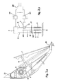
- FIG. 1 is a pedal board 7 rotatably articulated to a housing 23 of a pedal module.
- a cam 3 is rotatably arranged.
- a coupling lever 50 engages a coupling lever 50, which cooperates with a fixedly connected to the cam pivot lever 51. It can be seen that during a rotational movement of the pedal lever 7 in the counterclockwise direction, the cam 3 is rotated clockwise.
- a restoring force applying return spring 4 which is often referred to as a return spring or return spring.
- FIG. 1 illustrated inventive structure for the fact that in an excess of the actual value compared to the target value of the speed, an electric motor 1 with a connected gear 13 exerts a force on the pedal lever 7, which is the restoring force of the return spring 4 is added.
- the connection between the retraction rod and the cam via a bypass spring 57 takes place. It is meant by “transgress” the following.
- the driver is given the opportunity, contrary to the force exerted by the retraction rod 54, to be able to depress the pedal lever 7 in the counterclockwise direction.
- the escape spring 57 is for this purpose between the cam. 3 and the retraction rod 54 is switched.
- the retraction rod suspension can deflect upwards within the cam so as to avoid sudden acceleration due to a malfunction in the force feedback unit (for example, reverse rotation of the engine).
- the suspension 58 is guided in a groove 59 in such a way that it can engage the wall 59 of the groove 59 and can rotate the cam disk 3 in the counterclockwise direction via tensile forces. Compressive forces can not be transmitted because the suspension 58 can escape upwardly within the groove 60.
- the connection between the cam and the retraction rod can be made via a rope. It only has to be ensured that the power transmission can only take place in one direction.
- connection between the retraction rod 54 and the engine-transmission unit 1, 13 can, as in FIG. 1 is shown, via positive engagement but also via friction.
- the engine In order to directly have a higher engine torque available when connecting the force feedback function, the engine first runs against a blocked transmission which is not shown in detail. By shifting the retraction rod to the bottom right, the locking of the transmission is released in unspecified form and you have thus immediately the full engine torque for the force feedback function available.
- Fig. 1 The benefits of using Fig. 1 described device that the engine only needs to be switched on or off. No position recognition is required for the motor. The engine only needs to turn in one direction. No reversing operation required. The parts can be made of plastic. The system does not have to be set to different load conditions.
- Fig. 2a and 2b The embodiment according to Fig. 2a and 2b is based on the usual construction of a pedal module within the housing 23.
- the basic structure of the standard module is again the same as in the previous embodiment. Since the analog reference numerals have been used in so far apply the statements already made above.
- a pedal board 7 is rotatably connected via the rotation axis 89 to the pedal module 23.
- a return cable 8 engages a return spring 4 via a cam 3 to a rotary lever 51, which acts via a coupling lever 50 on the pedal 7.
- the return spring 4 is formed by two mutually parallel springs. If you step on the pedal board 7, the coupling lever 50 is axially displaced, which is hinged to the rotary lever 51.
- the rotary lever 51 is fixedly connected to the cam 3, so that when pressing the pedal board 7, the cam 3 is rotated by a certain angle. The rotation takes place against the resistance of the return spring 4, which thus tries to pull the pedal 7 back to its original position, since it is connected via the return cable 8 with the cam. This way of working is standard with the usual pedal modules.
- the embodiment of the invention is characterized by the fact that on the return rope 8 and the two return ropes 8, a counter-stop 17 is fixed, which changes its position with the operation of the pedal board 7 by the expansion of the return springs 4. Between the two return springs 4, a spring 9 is arranged, which also like the return springs 4 acts on the housing 23.
- the adjusting spring 9 is connected at its other end via a return cable 110 with a pulley 230, which can be rotated via a motor / gear unit 230.
- the motor-gear unit 230 consists of an electric motor 1 and a gear 13.
- a stop 87 is fixed, the position of which is adjustable by operating the motor 1 by the motor via the pulley 230, the length of the spring 9 changes and thus shifts the position of the stop 87.
- Counter stop and stop are arranged so that they can engage behind when they are compared to each other. The stop 87 can therefore not pass the counter-stop 17, if he in Fig. 2b is lowered far enough down.
- the magnitude of the force with which the stop 87 acts on the counter-stop 17 can be controlled by the motor 1, wherein the maximum force is predetermined by the force of the pretensioned spring 9 via the motor.
- This adjustment of the adjusting force on the engine 1 is important insofar as otherwise the force is determined only by the force of the prestressed spring 9, wherein this force in turn depends on the bias of the spring 9 in the meeting of the two stops. But this bias is different depending on the instantaneous position of the counter-attack 17th
- Fig. 2b is indicated that the motor 1 is driven by an electric controller 240 when the measured by the control speeds s (is-speed and soll-speed) are equal or almost equal.
- the controller 240 can act on the electric motor 1 via a converter 241, wherein the converter supplies the electric motor with the corresponding current due to the voltage at the output of the controller 240.
- the controller To be able to act with a certain force on the stop 87 on the counter-stop 17 the controller must be informed, at which point the counter-stop 17 is located. Due to the speed alone is the location of the counter-attack 17 is not clearly established in advance, as this situation indeed depends on the possible loading of the vehicle, a possible uphill and the like.
- the position of the counter-attack 17 is at the time of transfer of the force (ie, for example, speed is equal speed) clearly defined by the rotational position of the cam 3. It is therefore recommended to measure the rotational position of the cam at the time of transfer and a another converter 241 to control the controller 240 accordingly. There is no attempt made on the basis of corresponding table values, which take into account not only the speed but also the other driving conditions such as loading, uphill and the like, stop stop 87 by readjustment before the target speed is reached. As already explained above, the position of the counter-attack is determined only when it has reached this position, in other words, at the time of transfer of additional power to the pedal. 7
- FIGS. 2a and 2b can be briefly summarized as follows. There are two return springs 8 and a single return spring 9 is provided. The action of the return spring 9 is effected by a stop 87 which acts on the two return cables 8 via a driver 17.
- a third spring (FFP spring) is used as the over-tread spring 9, which provides the maximum force feedback force.
- FFP spring is biased via a cable 110 by means of a motor-gear unit 1, 13.
- the FFP spring 9 is preloaded to the maximum and locked in this position. But the engine and / or the transmission can also be self-locking, whereby a corresponding locking device is not needed.
- a stop in the form of a driver or counter-stop 17 is attached on the cable 8 of the standard retraction springs 4.
- a stop 87 is attached on the cable 110 of the FFP spring .
- the FFP cable 110 is unlocked and the stop 87 of the FFP cable 110 is moved to the driver 17 of the standard cable 8.
- a force increased by the FFP spring force of the spring 9 must be applied to the pedal 7.
- the engine 1 can also draw with a defined force on the spring and thus support the foot force.
- an adjustable stop is used.
- the FFP switching state e.g, the speed is equal to the desired speed
- this stop is driven against the counterstop in such a way that the stop acts against the counterstop and thus against the pedal 7 with a (predetermined) force.
- Fig. 2a and 2b offer the following advantages: Faile-Safe behavior, ie with the gearbox or motor blocked, the pedal can still be operated with increased force.
- the FFP cable 110 simply buckles and no additional inertial forces occur.
- the system is stiff and very simple.
- the restoring force can be varied.
- a second electric motor can be used as a motor.
- FIGS. 3a and 3b show two embodiments of an embodiment, which strongly according to the embodiment.
- Figure 2a and 2b is ajar. While in the latter embodiment, a stationary pedal 7 is provided, which rotates about the rotation axis 89, the embodiment applies in FIGS. 2a and 2b described principle on a hanging pedal.
- FIG. 3a shows a hanging pedal lever 207 which is rotatably mounted about an axis of rotation 289 relative to a housing 223.
- the housing 223, not shown, represents the usual housing of a hanging pedal lever and has the usual structure, which will not be described in detail here.
- the pivot bearing 211 is fixedly connected to the housing 223.
- the pedal lever 207 engages via a pin 212 on the bearing 289, wherein the pin 212 is fixedly connected to the pedal lever 207.
- the pin 212 is associated with a rotary lever 214, so that the pedal lever 207 and the rotary lever 214 kinematically form a unit which is rotatable about the pivot bearing 211 in the housing 223.
- a roller 216 is rotatably mounted as a stop 216, so that via the rotary lever 214 only perpendicular to the rotary lever extending forces can be transmitted.
- a sleeve 217 is further firmly connected, which has at its one end a circumferential projection 218 on which a spring 219 is supported. The other end of the spring 219 engages a circumferential shoulder 220 of a plug 222, which is slidably guided in the sleeve 217.
- a unit 228 of engine and transmission is fixed.
- the motor is able to drive a tape reel 230 via the gearbox, whereby a tape or rope 234 can be wound up via the tape reel 230.
- the end of the tape opposite the wound end of the tape 234 engages the plug 222.
- the spring 219 is here dimensioned so that they can create in each position of the stopper 216, the plug 222 under bias at which stop 216.
- the standard pedal module 223 (not illustrated in detail) operates in the usual way, with the tape roll 230 holding the tape 234 wound up so far that the plug 222 is disengaged from the latter Stop 216 remains.
- the spring is under considerable bias.
- an electrical circuit When the actual speed reaches the desired speed, an electrical circuit outputs a signal by which the motor of the motor / gear unit 228 is turned on.
- the motor unwinds the tape roll 230 such that the stop 236 of the plug 222 engages the stop 216 of the rotary lever 214 and thereby exerts an additional force on the pedal lever 207.
- This force can be dimensioned by a suitable choice of the spring 219.
- the stop 236 is held in this position by the engine and the transmission 228.
- a microswitch is attached to the plug 222, which can be switched by the stop 216. It is therefore possible to deliver an electrical signal through the microswitch 237 when the (additional) actuating force on the rotary lever 214 and thus the pedal lever 207 begins to act.
- This electrical signal may serve, for example, to shut off the engine of the unit 228 and / or to indicate to the driver that the actuating force has become effective.
- the embodiment of the embodiment according to FIG. 3b is different from the after FIG. 3a essentially only in that the spring 219 in FIG. 3a is replaced by two series-connected and interleaved springs 238 and 249 arranged.
- the spring 219 in FIG. 3a comparable spring 238 in FIG. 3b is therefore not supported directly on the stop 216 but engages a sleeve-shaped intermediate member 252, Exils with its other end, the second spring 249 is supported.
- This second spring 249 then acts as already above in connection with FIG. 3a in the described on the plug 222 a.
- FIGS. 3a and 3b in other words, can be briefly described as follows.
- the construction is based on the spring concept according to the FIGS. 2a and 2b , which has already been described there in connection with a standing accelerator.
- the execution shown here acc. FIG. 3b is for a hanging gas pedal.
- This increased pedal force is generated via a spring assembly 218, 238, and 252, 249, 222. If the FFP function is switched off (no actuating force), the spring assembly is compressed. This happens because the tape 234 is wound on the tape roll 230 via the motor / gear unit 228.
- the engine can be switched off after winding the tape, it is advantageous to use a self-locking gear. However, it can also be used a locking mechanism for fixing the end position.
- the FFP function is switched on (insertion of the actuating force)
- the spring assembly is released to the transfer point.
- the driver is informed by the increase of the pedal force reaching a predefined driving condition.
- the microswitch integrated in the stop of the FFP module is switched. In this way, reaching the transfer point can be accurately determined.
- a conceivable solution is that instead of a microswitch, the contact surfaces of the attacks as switch contacts be used.
- FIG. 3a Another embodiment shows FIG. 3a , In this variant, only one spring is used to generate the FFP force.
- the advantage of the variant in FIG. 3b with the two springs connected in series is that the spring rate is reduced and thus the increase in power over the pedal stroke is lower.
- the increase in power over the pedal stroke can be compensated by the motor by gently energized him and he constantly pulls on the band 234 and thus the required pedal force is lowered. If the current is slightly increased above the pedal stroke, an approximately constant pedal force can be generated. In this way, of course, the strength level can be adjusted in general.
Abstract
Description
Die Erfindung betrifft eine Vorrichtung nach dem Oberbegriff des Patentanspruchs 1.The invention relates to a device according to the preamble of
Die Erfindung betrifft eine Vorrichtung zur Steuerung eines Parameters eines Kraftfahrzeuges (beispielsweise der Geschwindigkeit eines Fahrzeugs) welche ein als Pedal ausgestaltetes Steuerorgan aufweist. Über das Steuerorgan beispielsweise das Gas-Pedal (oder Bremspedal) wird in die Zufuhr von Treibstoff zu dem Motor und damit die Fahrgeschwindigkeit des Fahrzeugs gesteuert (oder über die Aktivierung des Bremssystems die Geschwindigkeit reduziert). Für eine sichere und vorschriftsmäßige Fahrweise eines Fahrzeugs ist die Einhaltung einer geeigneten und/oder vorgeschriebenen Geschwindigkeit sehr wichtig. Um die augenblickliche Geschwindigkeit eines Fahrzeugs zu erkennen, muss der Fahrer bei den bekannten Anzeigen diese an einem Tachometer ablesen. Während der Zeit, in der der Fahrer dieses Meßinstrument abliest und das Ergebnis bewertet ist es ihm nur bedingt möglich auf den Verkehr zu achten.The invention relates to a device for controlling a parameter of a motor vehicle (for example, the speed of a vehicle) which has a designed as a pedal control member. For example, the gas pedal (or brake pedal) is controlled by the control member in the supply of fuel to the engine and thus the driving speed of the vehicle (or reduces the speed of the activation of the braking system). For a safe and proper driving of a vehicle, the observance of a suitable and / or prescribed speed is very important. In order to recognize the instantaneous speed of a vehicle, the driver must read off the readings on a speedometer with the known displays. During the time in which the driver reads this measuring instrument and assesses the result, he is only partially able to pay attention to the traffic.
Bei der Gestaltung eines Anzeigesystems insbesondere der Fahrgeschwindigkeit eines Fahrzeugs ist somit darauf zu achten, dass die Ablesung einerseits und die Durchführung der eigentlichen Fahreraufgabe (Einhaltung des Kurses, der Geschwindigkeit und des Abstandes zu anderen Fahrzeugen) sich möglichst wenig gegenseitig behindern. Hierzu sollten Warnanzeigen beispielsweise hinsichtlich einer zu großen Geschwindigkeit, so auffällig und leicht interpretierbar sein wie möglich, so dass der Fahrer besonders schnell und fehlerfrei darauf reagieren kann. Die Reaktionszeit auf eine Anzeige ist um so kürzer, je kompatibler sie mit dem zugehörigen Bedienelement ist, das heißt je höher der erkennbare Zusammenhang zwischen der Anzeige und dem Bedienelement selber ist.When designing a display system in particular the driving speed of a vehicle is thus to ensure that the reading on the one hand and the implementation of the actual driver task (compliance with the course, the speed and distance to other vehicles) interfere as little as possible against each other. For this purpose, warning displays should be as conspicuous and easily interpretable as possible, for example, in terms of too high a speed, so that the driver can react to it very quickly and without errors. The reaction time a display is the shorter, the more compatible it is with the associated control, that is, the higher the apparent relationship between the display and the control itself.
Hierzu wurde aus der
In der
Aus der
In der
Bei der
Es hat sich gezeigt, dass die bekannt gewordenen Konstruktionen recht aufwendig sind und eine Reihe von der Praxis gestellten Forderungen nicht erfüllen. So muss unter anderem auch darauf geachtet werden, dass bei der Verwendung eines Elektromotors zum Aufbringen der FF-Funktion dieser nicht überlastet wird. Weiterhin muss Vorsorge dafür getroffen werden, dass unter keinen Umständen der Aktuator für die FF-Funktion bzw. die Vorrichtung selbsttätig die Geschwindigkeit des Fahrzeugs erhöhen kann und damit Gefahren verstärkt, die durch die Einrichtung gerade vermieden werden sollen. Weiterhin soll der Fahrer die volle Kontrolle über das Fahrzeug behalten. Das heißt, dem Fahrer muss es möglich sein das Gaspedal (bzw. Bremspedal) im Sinne einer höheren Geschwindigkeit oder eines stärkeren Bremsvorganges auch dann betätigen zu können wenn die FF-Funktion schon eingesetzt hat. Dieser Vorgang wird als "Übertreten" bezeichnet. Weiterhin muss sichergestellt sein, dass der Fahrer bemerkt, dass von seinem Fahrzeug die soll-Geschwindigkeit überschritten wurde. Dabei ist zu beachten, dass die auf das Pedal bei einer bestimmten Geschwindigkeit aufgebrachte Kraft sehr unterschiedlich sein kann, je nachdem wie stark das Fahrzeug beladen ist oder ob es bergauf oder bergab fährt. In der eben genannten
Die Erfindung geht daher aus von einer Vorrichtung, wie sie sich aus dem Oberbegriff des Hauptanspruches ergibt.The invention is therefore based on a device as it results from the preamble of the main claim.
Aufgabe der Erfindung ist es Verbesserungen der bekannten Konstruktionen zu beschreiben, durch welche die Herstellungskosten für die Vorrichtung reduziert werden, die Zuverlässigkeit der Arbeitsweise der Vorrichtung verbessert wird und zusätzlich vorteilhafte Merkmale eingeführt werden, welche die Handhabung der Vorrichtung in der Praxis vereinfachen. Einzelheiten zu der Problematik der bekannten Vorrichtungen lassen sich auch aus den Figuren 8a und 8c im Zusammenhang mit in der zugehörigen Beschreibung entnehmen.The object of the invention is to describe improvements of the known constructions, by which the manufacturing costs for the device are reduced, the reliability of the operation of the device is improved and additionally advantageous features are introduced, which simplify the handling of the device in practice. Details of the problem of the known devices can also be taken from the figures 8a and 8c in connection with in the accompanying description.
Aufgabe der Erfindung ist es weiterhin die Möglichkeit sicherzustellen dass die gattungsgemäße Vorrichtung auch dann Übertreten werden kann, wenn die vorbekannten Übertretungsmittel blockiert sind. Damit ist gemeint, dass das Bremspedal entgegen der Wirkung der Rückstellkraft (FFP-Funktion) nieder getreten werden kann. Das ist beispielsweise dann wichtig, wenn eine Gefahrensituation am besten durch Beschleunigen des Fahrzeugs - beispielsweise zum Überholen - beseitigt werden kann. Dabei hat sich herausgestellt, dass diese Übertretungsmittel blockiert sein können, sodass ein Übertreten nicht mehr möglich ist. Dieser Zustand ist als nachteilig zu betrachten. Es soll also unter allen Umständen vermieden werden, dass durch eine in Richtung der Rückbewegung des Pedals auftretende Kraft zur Erhöhung einer Gefahrensituation führen kann anstatt diese zu beseitigen - auch für den Fall einer Blockade der Übertretungsmittel.The object of the invention is also to ensure the possibility that the generic device can be violated even if the known violation means are blocked. This means that the brake pedal can be stepped against the action of the restoring force (FFP function). This is important, for example, when a dangerous situation can best be eliminated by accelerating the vehicle - for overtaking, for example. It has been found that these means of violation can be blocked, so that a trespassing is no longer possible. This condition is considered disadvantageous. It should therefore be avoided under all circumstances that can occur by increasing the direction of the return movement of the pedal force to increase a dangerous situation instead of eliminating them - even in the event of a blockade of transgressions.
Die Aufgabe wird durch die sich aus dem kennzeichnenden Teil des Hauptanspruches ergebende Merkmalskombination gelöst. Dabei ist vorgesehen, dass der Aktuator durch ein Stellsignal angesteuert wird, welches von der Abweichung einer Messgröße des Fahrzeugs von einem Sollwert, insbesondere der Fahrgeschwindigkeit von einer vorgegebenen Sollgeschwindigkeit oder Bremskraft von einer zulässigen Bremskraft, ausgelöst wird oder zumindest abhängig ist und dass die Stellkraft in Abhängigkeit von der Abweichung des Sollwertes insbesondere der ist-Geschwindigkeit von der soll-Geschwindigkeit auf das Steuerorgan einwirkt und dass Notfallmittel vorgesehen sind, die ein Übertreten des Pedals entgegen der Stellkraft auch dann gestatten, wenn die Übertretmittel eine Blockade aufweisen. Als Notfallmittel ist dabei eine Sicherheits-Feder in den Kraftfluss zwischen Aktuator und Pedal geschaltet ist und dass die Federkonstante dieser Sicherheits-Feder derart ausgewählt ist, dass sie erst dann elastisch nachgibt wenn die auf das Pedal ausgeübte Betätigungskraft eine bestimmte Schwelle überschreitet. Der Aktuator ist mit einem Getriebe versehen, über welches er die Stellkraft an das Pedal abgibt, wobei das Getriebe ein Kugel-Gewinde-Trieb ist, der durch eine Gewinde-Spindel und eine Gewinde-Mutter gebildet ist. Die Gewinde-Spindel wirkt unmittelbar auf das Pedal ein und die Gewinde-Spindel oder die Gewinde-Mutter ist in axialer Richtung durch eine Übertretfeder elastisch gelagert.The problem is solved by the resulting from the characterizing part of the main claim feature combination. It is provided that the actuator is controlled by an actuating signal which is triggered by the deviation of a measured variable of the vehicle from a desired value, in particular the driving speed of a predetermined desired speed or braking force of an allowable braking force, or at least dependent and that the force in Dependence on the deviation of the setpoint, in particular the speed of the target speed acts on the control member and that emergency means are provided which allow a trespassing of the pedal against the force even if the Übertretmittel have a blockage. As emergency means while a safety spring is connected in the power flow between the actuator and the pedal and that the spring constant of this safety spring is selected such that it gives way elastically only when the force exerted on the pedal operating force exceeds a certain threshold. The actuator is provided with a gear via which it outputs the actuating force to the pedal, wherein the gear is a ball-threaded drive, which is formed by a threaded spindle and a threaded nut. The threaded spindle acts directly on the pedal and the threaded spindle or the threaded nut is elastically supported in the axial direction by a Übertretfeder.
Zum einen wird die zusätzliche Stellkraft (also die FF-Funktion) durch einen elektromechanischen Aktuator bereitgestellt. Dieser Aktuator ist vorteilhaft in Abhängigkeit von einer ganzen Reihe von Parametern steuerbar. Dies kann beispielsweise durch eine geeignete elektronische Schaltung wie durch einen Prozessor geschehen. Auf diese Weise ist es möglich die Stellkraft nicht nur von der Größe der Abweichung der ist-Geschwindigkeit von der soll-Geschwindigkeit abhängig zu machen. Vielmehr kann auch berücksichtigt werden mit welcher Kraft der Fahrer gerade das Gas-pedal bedient, so dass sich die Stellkraft hiervon abhängig einstellen läßt. Auf diese Weise läßt sich vermeiden, dass der Fahrer beispielsweise bei einer Bergfahrt, bei der das Pedal mit größerer Kraft bedient werden muss, bei nur geringer Geschwindigkeitsüberschreitung die einsetzende relativ kleine Stellkraft nicht spürt. Die Stellkraft soll also zwar qualitativ von der Differenz der Geschwindigkeiten aber nicht quantitativ von dieser Differenz abhängig sein. Anders ausgedrückt, auch bei einer kleinen Abweichung der ist-Geschwindigkeit von der soll-Geschwindigkeit soll die Stellkraft mit hinreichender Größe einsetzen, damit der Fahrer spürt, dass nunmehr die soll-Geschwindigkeit überschritten wurde und das Pedal von dem Aktuator zurückgestellt wird.On the one hand, the additional actuating force (ie the FF function) is provided by an electromechanical actuator. This actuator is advantageously controllable depending on a number of parameters. This can be done for example by a suitable electronic circuit such as by a processor. In this way it is possible not only the power depending on the size of the deviation of the is-speed of the target speed. Rather, it can also be taken into account with which force the driver is currently operating the gas pedal, so that the actuating force can be adjusted depending on this. In this way, it can be avoided that the driver, for example, in a mountain driving, in which the pedal must be operated with greater force, with little speed exceeding the onset of relatively small actuating force does not feel. Although the force should be qualitatively dependent on the difference in the speeds but not quantitatively of this difference. In other words, even with a small deviation of the actual speed from the target speed, the actuating force should be of sufficient magnitude to allow the driver to feel that the target speed has now been exceeded and the pedal is reset by the actuator.
Schließlich soll es für den Fahrer möglich sein in Sonderfällen die Stellkraft überwinden zu können. Hierbei ist an Gefahrensituationen gedacht, bei denen eine Reduzierung der Geschwindigkeit mit einer erhöhten Gefahr verbunden sein kann, etwa bei einem Überholvorgang vor einer Bergkuppe. Dieser Vorgang wird vielfach als Übertreten bezeichnet.Finally, it should be possible for the driver to overcome the force in special cases. This is intended for dangerous situations in which a reduction in speed may be associated with an increased risk, such as in an overtaking process in front of a hilltop. This process is often referred to as trespassing.
Es sollen unter anderen Mittel vorgesehen sein, durch welche die zusätzliche Stellkraft einschließlich der ohne dies vorgegebenen Rückstellkraft durch den Fahrer übertreten werden kann. Damit ist gemeint, dass der Fahrer nicht der von dem Aktuator insbesondere Elektro-Motor ausgeübten, das Pedal zurück stellenden Stellkraft nachgibt sondern dieser Kraft standhält und somit das Pedal in seiner Lage verharrt oder sogar dass der Fahrer eine größere Kraft ausübt, durch welche das Pedal entgegen der Stellkraft im Sinne einer höheren Geschwindigkeit tiefer nieder getreten wird. Um das zu ermöglichen sind zwei Ausgestaltungen der erfindungsgemäßen Vorrichtung möglich. Wenn die Kraftquelle beispielsweise der Elektro-Motor reversiert werden kann, also entgegen seiner Antriebsrichtung bewegt werden kann, so läßt sich das "Übertreten" in einfacher Weise dadurch ermöglichen, dass der Antrieb durch eine entsprechende hohe Pedalkraft überwunden wird und der Motor auf diese Weise praktisch gezwungen wird, sich ein Stück rückwärts zu drehen.It should be provided, among other means by which the additional force, including without this predetermined restoring force can be exceeded by the driver. By this it is meant that the driver does not yield the actuating force exerted by the actuator, in particular electric motor, the pedal restores force but withstands this force and thus the pedal remains in position or even that the driver exerts a greater force by which the pedal against the force in the Deeper down in the sense of a higher speed. To enable this, two embodiments of the device according to the invention are possible. If the power source, for example, the electric motor can be reversed, so can be moved against its drive direction, so can the "trespassing" in a simple manner allow the drive is overcome by a correspondingly high pedal force and the motor in this way practically is forced to turn backwards a bit.
Läßt sich die Kraftquelle aber nicht reversieren, so muss, um das Übertreten zu ermöglichen in den Kraftweg ein elastisches Glied eingefügt werden, welches bei hinreichend großer auf das Pedal ausgeübter Kraft nachgibt und so ein Niedertreten des Pedals entgegen der Stellkraft gestattet. Das elastische Glied beispielsweise Stahlfeder muss eine hinreichend große Vorspannung besitzen da andernfalls die Feder nachgibt ohne eine größere Kraft auf das Pedal auszuüben und so der Fahrer durch das Ansprechen der Force-Feedback-Pedal-Einrichtung (FFP-Einrichtung) nicht gewarnt wird. Anderseits wird angestrebt, dass die Federkonstante der Feder klein ist, damit sich die Stellkraft nicht zu stark mit der Stellung des Pedals ändert.But if the power source can not be reversed, an elastic member must be inserted in the force path, in order to allow the trespassing, which yields with a sufficiently large force exerted on the pedal and thus allows the pedal to depress against the actuating force. The elastic member, for example steel spring, must have a sufficiently large preload, otherwise the spring will yield without exerting a greater force on the pedal and so the driver is not warned by the response of the Force Feedback Pedal (FFP) device. On the other hand, it is desirable that the spring constant of the spring is small so that the force does not change too much with the position of the pedal.
Selbst wenn aber die Kraftquelle reversiert werden kann, so ist es dennoch sehr zweckmäßig das beschriebene elastische Glied in den Kraftweg einzufügen. In Notsituationen kann es nämlich notwendig sein, dass das Pedal derart schnell nieder gedrückt werden muss, so dass die reversierende Kraftquelle und/oder ein dazwischen geschaltetes Getriebe nicht zu folgen vermag und quasi blockiert oder auch tatsächlich blockiert ist. Für diese Fälle wird vorgeschlagen auch bei Anwendung einer reversierenden Kraftquelle das beschriebene elastische Glied in den Kraftweg einzufügen.Even if, however, the power source can be reversed, it is nevertheless very expedient to insert the described elastic member into the force path. In emergency situations, it may be necessary for the pedal to be pressed down so quickly that the reversing power source and / or a transmission connected therebetween are unable to follow and are virtually blocked or actually blocked. For these cases, it is proposed to insert the described elastic member into the force path even when using a reversing force source.
Es wird vorgeschlagen, dass die Stellkraft sprungartig einsetzt. Hiermit ist gemeint, dass die Stellkraft nicht schleichend auftreten soll, so dass der Fahrer kaum merkt, dass die zusätzliche Stellkraft (FFP-Kraft) eingesetzt hat und möglicherweise der Täuschung unterliegt, dass Pedal-Gefühl habe sich geändert. Vielmehr ist es erwünscht, dass die zusätzliche Stellkraft ruckartig einsetzt und den Fahrer nicht in Zweifel darüber läßt, dass die Regelung das Pedal entgegen der Betätigungskraft des Fahrers zurück stellen will. Hierdurch läßt sich die notwendige Alarm-Wirkung erzielen. Wächst dagegen z. B. die Stellkraft mit der Differenz zwischen ist-Geschwindigkeit und soll-Geschwindigkeit an, so wird das faktische Anwachsen der Rückstellkraft am Pedal möglicherweise nur als ein verändertes Pedalgefühl nicht aber als Warnung verstanden.It is suggested that the actuating force starts suddenly. By this is meant that the control force should not occur creeping, so that the driver hardly realizes that the additional force (FFP force) has deployed and may be subject to the deception that pedal feel has changed. Rather, it is desirable that the additional actuating force starts jerkily and does not leave the driver in doubt about the fact that the control wants to put the pedal back against the operating force of the driver. As a result, the necessary alarm effect can be achieved. Grows against z. B. the force with the difference between is-speed and target speed, so the actual increase in the restoring force on the pedal may be understood as a changed pedal feeling but not as a warning.
Da zur Steuerung von Fahrzeugen außer mechanischen auch hydraulische und pneumatische Kräfte angewendet werden besteht die Möglichkeit, den Aktuator auf diese Weise mit Energie zu versorgen. Es kann stattdessen einen Elektromotor einzusetzen. Durch die Verwendung eines Elektromotors als Kraftquelle läßt sich diese nicht nur sehr einfach mittels elektrischer Signale starten. Darüber hinaus kann diese Kraftquelle auch sehr leicht eingegebenen Steuersignalen folgen, so dass die Höhe der zusätzlichen Stellkraft sich während des FFP-Vorgangs leicht an zusätzliche Randbedingungen anpassen läßt. So kann beispielsweise die zusätzliche Stellkraft von der Höhe der gerade herrschenden normalen Rückstellungskraft und damit von der Pedalstellung abhängig gemacht werden. Hierdurch läßt sich sicherstellen, dass die zusätzliche Stellkraft immer in einem weitgehend gleichbleibenden Verhältnis zur beim Einsetzen der Stellkraft gerade aufgewendeten Rückstellkraft bleibt.Since hydraulic and pneumatic forces are used to control vehicles in addition to mechanical ones, it is possible to supply the actuator with energy in this way. It can instead use an electric motor. By using an electric motor as a power source, these can not only start very easily by means of electrical signals. In addition, this power source can also follow very easily input control signals, so that the amount of additional force can be easily adapted to additional constraints during the FFP process. Thus, for example, the additional force of the height of the currently prevailing normal restoring force and thus be made dependent on the pedal position. As a result, it can be ensured that the additional actuating force always remains in a largely constant relationship to the restoring force which has just been expended when the actuating force is applied.
Es wird dafür Sorge getragen, dass nur eine in einer vorgegebenen Richtung wirkende Stellkraft wirksam werden kann, eine in Gegenrichtung wirkende Stellkraft aber sicher verhindert wird. Dies kann beispielsweise durch eine entsprechende Auswahl des Motortyps oder aber mechanisch durch geeignete Anschläge bewirkt werden. Diese Maßnahme ist insbesondere auch deshalb wichtig, weil ausgeschlossen werden muss, dass durch eine Fehlfunktion die Regelung das Fahrzeug beschleunigt anstatt dafür zu sorgen, dass das Gaspedal zurückgeschoben und damit die Geschwindigkeit abgesenkt wird. Weiter unten werden hierzu auch spezielle Bauelemente beschrieben, welche eine Kraft nur in einer einzigen Richtung übertragen können wie beispielsweise die Übertragung von Zugkräften durch Seile oder Bänder. Des weiteren müssen also Maßnahmen getroffen sein, um sicher zu verhindern, dass bei einer Fehlfunktion des Aktuators dieser nicht den Gashebel (bzw. Bremshebel) in die verkehrte Richtung fahren kann, also die Geschwindigkeit des Fahrzeugs erhöht statt sie abzusenken. Weiterhin soll die Stellkraft nur solange wirksam sein, wie die ist-Geschwindigkeit die soll-Geschwindigkeit überschreitet. Es ist also sicherzustellen, dass die Stellkraft sich bei Unterschreiten der soll-Geschwindigkeit nicht umkehrt, etwa um den Fahrer zu zwingen sich an die eingestellte soll-Geschwindigkeit zu halten.It is ensured that only one acting in a predetermined direction actuating force can be effective, but a force acting in the opposite direction but is reliably prevented. This can be effected, for example, by an appropriate selection of the engine type or mechanically by suitable stops. This measure is particularly important because it must be ruled out that by a malfunction, the control accelerates the vehicle instead of ensuring that the accelerator pedal is pushed back and thus the speed is lowered. Below, special components are described for this purpose, which can transmit a force only in a single direction, such as the transmission of tensile forces by ropes or belts. Furthermore, therefore, measures must be taken to prevent sure that in case of malfunction of the actuator this can not drive the throttle (or brake lever) in the wrong direction, so the speed of the vehicle increases instead of lowering it. Furthermore, the force should be effective only as long as the is-speed exceeds the target speed. It must therefore be ensured that the actuating force does not reverse when the speed falls below the target speed, for example to force the driver to keep to the set desired speed.
Wie weiter unten erläutert wird können in besonders einfacher Weise die Mittel zum Übertreten des Pedals entgegen der FFP-Kraft darin bestehen, dass die die zusätzliche Stellkraft zur Verfügung stellende Kraftquelle durch eine entsprechend hohe Betätigungskraft an der Pedale zu einer Bewegung entgegen ihrer Antriebsrichtung gezwungen werden kann. Besteht die Kraftquelle beispielsweise aus einem Elektromotor, so kann ein Übertreten darin bestehen; dass der eingeschaltete Motor durch die übertretende Kraft zu einer Bewegung entgegen seiner Antriebsrichtung gezwungen wird. Dabei muss aber sichergestellt werden, das ein Übertreten auch dann möglich ist, wenn der Motor und/oder das zwischen Motor und Pedal geschaltete Getriebe bei hohen Pedalkräften bzw. hohen Pedal -Betätigungsgeschwindigkeiten (z. B. schnelles Durchtreten des Gaspedals) blockieren. Dazu werden hierfür geeignete Maßnahmen vorgeschlagen, die nachfolgend vielfach als fail-safe-Einrichtungen bezeichnet werden. Eine zweckmäßige Lösung kann darin bestehen, in den Antriebweg der Kraftquelle eine steife Feder zu legen, die bei üblichen Übertret-Kräften wie ein unelastischer Gegenstand wirkt. Werden die Kräfte aber zu groß, was durch eine Blockade bedingt sein kann, so gibt die Feder nach und ermöglicht so eine Bewegung des Pedals entgegen der FFP-Kraft.As will be explained below, in a particularly simple manner, the means for crossing the pedal against the FFP force can be that the force source providing the additional actuating force can be forced to move counter to its drive direction by a correspondingly high actuating force on the pedals , If, for example, the power source consists of an electric motor, a violation may exist therein; that the switched-on engine through the trespassing Force is forced to move against its drive direction. It must be ensured, however, that trespassing is also possible if the engine and / or the gearbox connected between the engine and the pedal block high pedal forces or high pedal actuation speeds (eg rapid passage of the accelerator pedal). For this purpose, suitable measures are proposed, which are often referred to below as fail-safe devices. A convenient solution may be to place in the drive path of the power source a stiff spring which acts at usual Übertret forces as an inelastic object. However, if the forces are too great, which may be due to a blockage, so gives the spring and allows movement of the pedal against the FFP force.
Um die das Pedal zurück drückende Kraft schlagartig zu erhöhen wird vorgeschlagen, anstatt der Kupplung einen unter Vorspannung stehenden Anschlag zu verwenden. Dabei kann der Anschlag ständig unter einer bestimmten Vorspannung stehen oder die Vorspannung wird erst dann aufgebaut, wenn die ist-Geschwindigkeit sich der soll-Geschwindigkeit nähert. Im Prinzip ist es nur notwendig, dass der Anschlag an der Stelle steht, die ein mit dem Pedal gekoppelter Gegenanschlag erreicht, wenn die soll-Geschwindigkeit überschritten wird. Ein Problem kann allerdings darin bestehen, dass die Lage des Pedals bei einer bestimmten Geschwindigkeit nicht eindeutig ist, da diese nicht nur von dem Zustand des Fahrzeugs (Belastung) sondern auch von dem Zustand der Fahrstrecke (Bergfahrt) abhängt. Bei der Vor-Einstellung der Lage des Anschlages ist somit darauf zu achten, dass die genannten Faktoren berücksichtigt werden. Die grundsätzliche Überlegung hierzu besteht darin, dass im Zeitpunkt der Einschaltung der FFP-Kraft diese zusätzliche Stellkraft auf das Pedal ausgeübt werden kann, ohne dass bekannt sein muss, wo das Pedal nun genau steht. Es ist also nur notwendig zu dem Zeitpunkt, bei dem die ist-Geschwindigkeit die soll-Geschwindigkeit erreicht, die zusätzliche Stellkraft an dem Pedal oder an dem zu dem Pedal führenden Kraftweg angreifen zulassen um die erwünschte Wirkung zu erzielen.To abruptly increase the force pushing back the pedal, it is proposed to use a biased stop instead of the clutch. In this case, the stop can constantly be under a certain bias or the bias voltage is built only when the is-speed approaches the target speed. In principle, it is only necessary that the stop is at the point that reaches a coupled with the pedal counter-stop when the target speed is exceeded. A problem may, however, be that the position of the pedal at a certain speed is not clear, since this depends not only on the condition of the vehicle (load) but also on the condition of the route (uphill). When pre-setting the position of the stop is thus to ensure that the factors mentioned are taken into account. The basic consideration for this is that at the time of FFP power application, this additional force can be exerted on the pedal without having to know where the pedal is now. It is So only necessary at the time when the is-speed reaches the target speed, allow the additional force on the pedal or on the force leading to the pedal force path to achieve the desired effect.
Der Elektromotor läuft also erst dann an, wenn die zusätzliche Stellkraft wirksam werden soll. Eine Voreinstellung eines Anschlages und die damit verbundenen, weiter oben geschilderten Probleme werden hierdurch einfach vermieden.The electric motor starts so only when the additional force is to be effective. A default setting of a stop and the associated problems described above are thereby simply avoided.
Um zu erreichen, dass die gewünschte Stellkraft sprungartig einsetzt wird vorgeschlagen, den Aktuator mit einer Kupplung zu versehen. Durch das Einschalten der Kupplung läßt sich die von dem Motor aufgebrachte Kraft schlagartig auf das Pedal übertragen. Nähere Ausführungen zu einem vorteilhaften Aufbau einer derartigen Kupplung werden weiter unten aufgeführt.In order to achieve that the desired actuating force starts suddenly, it is proposed to provide the actuator with a clutch. By switching on the clutch, the force applied by the engine can be suddenly transferred to the pedal. Further details of an advantageous structure of such a coupling are listed below.
Die von dem Aktuator abgegebene Stellkraft wird durch ein Übertragungsglied eingespeist. Um nun sicherzustellen, dass in Sonderfällen der Fahrer die Stellkraft überwinden kann (übertreten) wird vorgeschlagen, das Stellglied selbst oder aber seine Lagerung elastisch auszubilden, so dass es ab einer bestimmten Betätigungskraft durch den Fahrer ausweichen kann und ein Verstellen der Pedale in Richtung höherer Geschwindigkeit erlaubt.The output by the actuator force is fed by a transmission link. To ensure that in special cases, the driver can overcome the force (transgress) is proposed to form the actuator itself or its storage elastic, so that it can escape from a certain operating force by the driver and an adjustment of the pedals in the direction of higher speed allowed.
Eine besonders einfache Dimensionierung der Stellkraft läßt sich dadurch erreichen, dass die Stellkraft vollkommen getrennt von der Rückstellkraft in das Pedal eingekoppelt wird. Auf diese Weise kann der Aktuator unabhängig von der Rückstellkraft in Richtung Pedal-Modul wirksam werden. Es ist auf diese Weise auch leichter möglich den Aktuator in seiner Wirkung auf die Rückstellkraft abzustimmen.A particularly simple dimensioning of the actuating force can be achieved in that the actuating force is coupled completely separated from the restoring force in the pedal. In this way, the actuator can be effective regardless of the restoring force in the direction of the pedal module. It is also easier in this way the actuator in its effect on the restoring force vote.
Eine relativ einfache Konstruktion läßt sich dadurch erreichen, dass die Übertragungswege für die Stellkraft und die Rückstellkraft weitgehend gemeinsam genutzt werden. Dies kann beispielsweise dadurch geschehen, dass sowohl der Aktuator als auch die Quelle für die Rückstellkraft an der Umlenkrolle in dem Pedal-Modul angreifen. Das kann an einem gemeinsamen Angriffspunkt geschehen oder aber auch an unterschiedlichen Angriffspunkten.A relatively simple construction can be achieved in that the transmission paths for the restoring force and the restoring force are largely shared. This can be done, for example, that both the actuator and the source of the restoring force on the pulley in the pedal module attack. This can be done at a common point of attack or at different points of attack.
Wählt man einen gemeinsamen Angriffspunkt, so kann auch das über die Umlenkrolle geführte Zugseil gemeinsam genutzt werden, so dass in Kraftrichtung vor der Umlenkrolle sowohl die Quelle für die Rückstellkraft als auch der Aktuator an den Zugseil angreifen. Dabei können die Rückstellkraft und die Stellkraft in Reihe geschaltet werden, die beiden Kräfte werden also hintereinander in das Zugseil oder seine Verlängerung eingekoppelt. Der Vorteil ist hier, dass das Übertragungsglied des Aktuators an der Rückstellfeder aufgehängt werden kann also hierdurch elastisch verankert ist. Durch das Übertragungsglied läßt sich durch Verkürzung des Seilzuges die Zugkraft der Rückstellfeder schlagartig vergrößern, so dass die Zugkraft um die Größe der Stellkraft vergrößert ist. Der Fahrer kann aber die Stellkraft übertreten solange die Rückstellfeder noch weiter ausgezogen werden kann.If one chooses a common point of attack, then the pull cable guided over the deflection roller can be used in common, so that both the source for the restoring force and the actuator in the force direction in front of the deflection roller act on the pulling cable. The restoring force and the actuating force can be connected in series, so the two forces are coupled one behind the other in the traction cable or its extension. The advantage here is that the transmission member of the actuator can be suspended from the return spring so this is anchored elastically. By shortening the cable pull, the tensile force of the return spring can be abruptly increased by the transmission member, so that the tensile force is increased by the size of the actuating force. However, the driver can override the actuating force as long as the return spring can be extended even further.
Wie weiter oben schon erläutert wurde, kann eine Kupplung dazu verwendet werden, die Kraft des Aktuators schlagartig auf das Pedal einwirken zu lassen. Dabei kann die Kupplung die Stellkraft entweder unmittelbar auf das Pedal oder aber mittelbar, z. B. über das Zugseil und die Umlenkrolle übertragen. Es kann also die Kraft des Motors, der möglicherweise schon vor dem Überschreiten des soll-Wertes angelassen wird oder der ständig im Leerlauf mitläuft, durch die Kupplung schlagartig auf das Pedal gebracht werden, so dass die das Pedal zurück ziehende Kraft sprungartig anwächst. Für die Erzeugung der Vorspannung kann wahlweise eine Spiralfeder oder eine Schraubenfeder verwendet werden. Die Vorspannung wird bevorzugt durch einen Elektromotor aufgebaut, der anläuft, bevor der soll-Wert erreicht wird oder während der soll-Wert erreicht wird.As already explained above, a clutch can be used to let the force of the actuator act abruptly on the pedal. In this case, the clutch, the force either directly to the pedal or indirectly, z. B. transmitted via the traction cable and the pulley. It can therefore the power of the engine, which is possibly even before the exceeding of the target value is annulled or constantly idling, be brought abruptly on the pedal by the clutch, so that the pedal pulling back the force increases abruptly. For the generation of the bias voltage either a coil spring or a coil spring can be used. The bias voltage is preferably established by an electric motor, which starts before the target value is reached or while the target value is reached.
Ein bevorzugter Aufbau unter Verwendung eines Anschlages kann darin bestehen, dass ein Elektromotor über ein Seil mit einer die Stellkraft aufbauenden Feder verbunden ist. Zieht der Elektromotor die Feder in die Länge so ist ein an dem Seil befestigter Anschlag nur mit einer entsprechend größeren Kraft in seiner Lage zu verändern. Befestigt man nun an das Zugseil der Rückstellfeder einen Gegenanschlag, so kann über die Änderung der Lage des Anschlages durch den Elektromotor der Punkt festgelegt werden, bei dem die Stellkraft wirksam wird. Dieses Prinzip ist auch dann gut anwendbar, wenn zwei Rückstellfedern vorgesehen sind, wie dies in der Praxis üblich ist. Aus Gründen der Symmetrie empfiehlt es sich in diesem Fall für jede der beiden Rückstellfedern einen Gegenanschlag vorzusehen, die gegen den von dem Elektromotor eingestellten Anschlag laufen.A preferred construction using a stop may be that an electric motor is connected via a cable to a spring which builds up the actuating force. If the electric motor pulls the spring lengthwise, a stop attached to the cable can only be changed in its position with a correspondingly greater force. If now attached to the pull cable of the return spring a counter-stop, it can be set on the change of the position of the stop by the electric motor, the point at which the actuating force is effective. This principle is also well applicable when two return springs are provided, as is common in practice. For reasons of symmetry, it is advisable in this case to provide a counter-stop for each of the two return springs, which run counter to the stop set by the electric motor.
In der Regel ist es günstig, den Anschlag gegenüber dem Gehäuse des Pedalmoduls zu verstellen. Hierdurch wird der Abstand des Gegenanschlages gegenüber dem Pedalhebel verändert. Eine andere Möglichkeit besteht darin, den Anschlag gegenüber dem Gehäuse des Pedalmoduls ortsfest zu halten und dem Pedalhebel mit einem in seiner Lage änderbaren Gegenanschlag zu versehen. Die Verstellung kann dabei durch einen Elektromotor geschehen, welcher an dem Pedalhebel befestigt ist.In general, it is advantageous to adjust the stop relative to the housing of the pedal module. As a result, the distance of the counter-attack against the pedal lever is changed. Another possibility is to hold the stop relative to the housing of the pedal module stationary and to provide the pedal lever with a changeable in its position counter-stop. The adjustment can be done by an electric motor, which is attached to the pedal lever.
Wie weiter oben schon erläutert kann die Lage des Anschlages auf einer Kreisbahn verstellt werden. Das ist insbesondere dann vorteilhaft, wenn die Stellkraft durch eine mittels eines Elektromotors vorgespannte Spiralfeder aufgebracht wird. Bei der Verwendung einer Schraubenfeder ist es vorteilhaft, den Anschlag auf einer linearen Strecke zu verschieben. Diese Konstruktionen gehen davon aus, dass der Anschlag mechanisch fest arretiert wird. Es ist aber auch möglich, den Anschlag nur in einer Koordinatenrichtung zu arretieren. Hierzu kann beispielsweise ein Seil oder einen Band verwendet werden, an dessen Ende sich ein Anschlag befindet. In Abhängigkeit von dem gewünschten Lagepunkt des Anschlages wird dann das Seil oder Band entsprechend auf- oder abgewickelt. Das andere Ende des Bandes ist mit einer geeigneten Feder verbunden, die die gewünschte Stellkraft zur Verfügung stellt.As already explained above, the position of the stop can be adjusted on a circular path. This is particularly advantageous if the actuating force is applied by a biased by an electric motor coil spring. When using a coil spring, it is advantageous to move the stop on a linear path. These constructions assume that the stop is locked mechanically firmly. But it is also possible to lock the stop only in a coordinate direction. For this purpose, for example, a rope or a band can be used, at the end of which there is a stop. Depending on the desired position of the stop then the rope or band is wound up or unwound accordingly. The other end of the band is connected to a suitable spring, which provides the desired actuating force.
An sich ist es möglich, dass ein Linearmotor eine Stellkraft auf das Pedal direkt oder durch Umlenkung der Kraft indirekt ausübt. Eine derartige Maßnahme wird weiter unten als sehr einfache Lösung bei der Auswahl des Elektromotors vorgeschlagen. Dagegen kann eine preiswerte Lösung darin bestehen, einen üblichen Elektromotor mit drehendem Rotor vorzusehen und die Größe der auszuübenden Kraft so wie die vorzugsweise lineare Kraftrichtung mittels eines Getriebes herbeizuführen. Geeignete Ausgestaltungen hierfür werden weiter unten erläutert.As such, it is possible for a linear motor to exert a force on the pedal directly or indirectly by deflecting the force. Such a measure is proposed below as a very simple solution in the selection of the electric motor. In contrast, an inexpensive solution may be to provide a conventional electric motor with rotating rotor and bring about the size of the force to be exerted as well as the preferably linear direction of force by means of a gearbox. Suitable embodiments for this will be explained below.
Weiter oben war schon erläutert worden, dass es sich empfehlen kann, in dem Aktuator ein Getriebe einzusetzen. Hierbei empfiehlt sich die Verwendung eines Kugel-Gewinde-Triebes, welches sehr leichtgängig ist. Ist das Getriebe blockiert, so muss man dafür sorgen, dass der Fahrer die Gewinde-Spindel übertreten kann. Das geschieht dadurch, dass man die Spindel oder die Mutter des Getriebes elastisch lagert bzw. mit einem elastischen Glied versieht. Eine andere Möglichkeit besteht darin, die Selbsthemmung des Getriebes derart abzustimmen, dass ab einer bestimmten Betätigungskraft das Gewinde nachgibt, so dass der Fahrer auch in diesem Fall das Pedal übertreten kann. Hierbei handelt es sich um die normale Übertretfunktion.It has already been explained above that it may be advisable to use a gear in the actuator. Here, the use of a ball-threaded drive, which is very smooth. If the gearbox is blocked, it must be ensured that the driver can break the threaded spindle. This is done by having the spindle or nut of the gearbox elastically superimposed or provided with an elastic member. Another possibility is to tune the self-locking of the transmission in such a way that after a certain actuation force, the thread yields, so that the driver can also break the pedal in this case. This is the normal overriding function.
Die Spindel des Kugel-Gewinde-Triebes wirkt unmittelbar auf das als Pedal ausgestaltete Steuerorgan ein. Vorzugsweise greifen die Rückstellkraft und die Stellkraft an unterschiedlichen Punkten des Pedalhebels an.The spindle of the ball-threaded drive acts directly on the designed as a pedal control member. Preferably, the restoring force and the actuating force engage at different points of the pedal lever.
Anstatt eines der Elemente des Getriebes elastisch zu lagern, damit der Fahrer das Pedal übertreten kann ist es auch möglich eine spezielle Feder vorzusehen, die in den Kraftweg der Stellkraft eingefügt wird. Weiter oben wurde schon erläutert, dass unter Umständen die für die Rückstellkraft sorgende Feder gleichzeitig auch die Aufgabe der Übertretfunktion übernehmen kann. Ist das nicht möglich, weil die Rückstellfeder nicht weiter ausgedehnt werden kann, so wird vorgeschlagen, eine spezielle Feder für die Übertretfunktion vorzusehen.Instead of elastically supporting one of the elements of the transmission, so that the driver can break the pedal, it is also possible to provide a special spring, which is inserted into the force path of the actuating force. It has already been explained above that, under some circumstances, the spring providing the restoring force can at the same time also assume the function of the overriding function. If this is not possible because the return spring can not be extended further, it is proposed to provide a special spring for the override function.
Weiterhin kann die Rückstellfeder zusätzlich auch noch für die Stellkraft sorgen, in dem sie durch den Aktuator so weit verlängert wird, dass die Rückstellkraft sich schlagartig erhöht. Damit kann diese Feder bei geeigneter Abstimmung alle drei Aufgaben übernehmen, nämlich die Rückstellkraft und die Stellkraft zur Verfügung stellen und auch die Übertretfunktion übernehmen. In vielen Fällen ist es aber ratsam zumindest eine zusätzliche Feder einzusetzen, da hierdurch unterschiedliche Federkonstanten eingesetzt werden können. Vielfach soll auch die Funktion der Rückstellfeder nicht verändert werden, etwa wenn der Aktuator wahlweise und zusätzlich zur Verfügung gestellt werden soll.Furthermore, the return spring can additionally provide for the actuating force, in which it is extended by the actuator so far that the restoring force increases abruptly. Thus, this spring can take over all three tasks with a suitable vote, namely provide the restoring force and the force available and also take over the override function. In many cases, however, it is advisable to use at least one additional spring, as this allows different spring constants to be used. In many cases, the function of the return spring should not be changed, such as when the actuator is optional and in addition to be made available.
Verwendet man zwei oder mehr Federn, so kann es sich aus Gründen der Platzersparnis empfehlen, diese ineinander zu schachteln. Dies ist auch dann möglich, wenn die Federn in Reihe geschaltet werden also in ihrer Wirkung hintereinander liegen. Einige der nachfolgenden Ausführungsbeispiele zeigen hier Einzelheiten. Vorteilhaft dabei ist, dass die verschiedenen Federn eine unterschiedliche Federkonstante aufweisen können.If two or more springs are used, it may be advisable to nest them in order to save space. This is also possible if the springs are connected in series, that is, their effect is consecutive. Some of the following embodiments show details here. The advantage here is that the different springs may have a different spring constant.
Die weiter oben erwähnten Kupplungen können derart aufgebaut sein, dass sie die Kraftverbindung zwischen Elektromotor und Pedalhebel durch Formschluß (beispielsweise durch Verzahnung) oder durch Reibschluß bewirken. Dabei können wieder die kuppelnden Elemente als Scheiben oder auch als Stangen ausgestaltet sein. Um die Elemente zum Einschalten der Kupplung zusammenzuführen können Elektromagnete verwendet werden. Es ist aber auch möglich die Trägheit der Elemente für den Schaltvorgang auszunutzen. Dies kann beispielsweise dadurch geschehen, dass eine Schaltwelle vorgesehen wird, welche mit einem Außengewinde versehen ist und leichtgängig in einer Gewinde-Hülse läuft, beispielsweise mittels eines Kugel-Gewindes. Beginnt nun ein Elektromotor die Gewinde-Hülse zu drehen, so bleibt die Schaltwelle aufgrund ihrer Trägheit stehen und fährt aus der Hülse heraus, wodurch die kuppelnden Elemente gegeneinander gefahren werden.The clutches mentioned above may be constructed such that they cause the force connection between the electric motor and the pedal lever by positive engagement (for example, by toothing) or by frictional engagement. Again, the coupling elements may be configured as discs or as rods. Electromagnets can be used to merge the elements to engage the clutch. But it is also possible to exploit the inertia of the elements for the switching operation. This can be done, for example, by providing a switching shaft which is provided with an external thread and runs smoothly in a threaded sleeve, for example by means of a ball thread. Now starts an electric motor to rotate the threaded sleeve, so the shaft remains due to their inertia and drives out of the sleeve, whereby the coupling elements are driven against each other.
Die Kupplung kann aber auch eine mit Zähnen oder einer Reibfläche versehene Stange besitzen, in die ein zugeordnetes zweites Kupplungselement durch einen Schaltmagneten oder eine Exzenter-Welle gekoppelt wird.However, the coupling can also have a rod provided with teeth or a friction surface into which an associated second coupling element is coupled by a switching magnet or an eccentric shaft.
Weiter oben und wurde schon erläutert, dass es sich besonders empfehlen kann, in dem Aktuator einen Linearmotor einzusetzen. Der Vorteil hierbei besteht insbesondere darin, dass der Linearmotor weder ein Getriebe noch eine Kupplung benötigt und zusätzlich in Form einer linearen Bewegung an dem Pedalhebel direkt angreifen kann. Wird der Induktor nicht bestromt, so leistet er gegenüber dem Pedalhebel praktisch keinen Widerstand. Durch einen einfachen Schaltvorgang , durch welchen der Induktor bestromt wird, läßt sich dann vorteilhaft durch die Reaktionsschiene eine Kraft auf dem Pedalhebel ausüben, da man für das sich bewegende Übertragungsglied (Reaktionsschiene) keine Stromzuführung benötigt, wenn es mit Dauermagneten versehen ist oder aus einem magnetisierbaren Werkstoff besteht. Es ist aber auch möglich die Reaktionsschiene gekrümmt auszuführen und den Induktor mit einem Drehhebel zu verwenden, welcher an der Kurvenscheibe angreift. Dieser Drehhebel kann gleichzeitig ein Teil des Koppelhebels sein, welcher in an sich bekannter Weise die Rückstellkraft zu dem Pedalhebel überträgt, welche von der Rückstellfeder in die Kurvenscheibe eingeleitet wird.Next up and has been explained that it is special can recommend using a linear motor in the actuator. The advantage here is, in particular, that the linear motor requires neither a gearbox nor a clutch and can additionally engage directly in the form of a linear movement on the pedal lever. If the inductor is not energized, it provides virtually no resistance to the pedal lever. By a simple switching operation, by which the inductor is energized, can then be advantageous by the reaction rail exert a force on the pedal lever, since you need for the moving transfer member (reaction rail) no power supply when it is provided with permanent magnets or from a magnetizable Material exists. But it is also possible to perform the reaction rail curved and to use the inductor with a rotary lever which engages the cam. This rotary lever can also be a part of the coupling lever, which in a conventional manner transmits the restoring force to the pedal lever, which is initiated by the return spring in the cam.
Verwendet man wie beschrieben, die Reaktionsschiene als Übertragungsglied, so kann diese auch innerhalb des Pedalmoduls in den Kraftweg der Rückstellfeder eingeschaltet werden. Dies geschieht am besten auf der Strecke zwischen der Rückstellfeder und der Kurvenscheibe.If, as described, the reaction rail is used as a transmission element, it can also be switched on within the pedal travel in the force path of the return spring. This is best done on the distance between the return spring and the cam.
Es wird angestrebt, die mechanisch und/oder elektrisch empfindlichen Teile vor möglicher Verschmutzung durch die umgebende Luft zu schützen. Hierzu wird vorgeschlagen die aus dem Gehäuse des Pedalmoduls herausragenden und mit dem Pedalhebel verbundenen beweglichen Teile mit Hilfe einer diese Teile umgebenden Manschette zu schützen. Andererseits ist dabei aber zu beachten, dass es möglich sein muss, den Pedalhebel gegenüber dem Gehäuse des Pedalmoduls sehr schnell bewegen zu können, beispielsweise bei einer Panik-Bremsung. Hierdurch wird aber der von der Umgebung abgedichtete Raum sehr schnell verengt, wodurch ein erheblicher Druck aufgebaut wird, welcher die Manschette gefährden kann. Daher wird vorgeschlagen, in dem Gehäuse ein Ventil vorzusehen, durch welches der Überdruck entweichen kann.It is desirable to protect the mechanically and / or electrically sensitive parts from possible contamination by the surrounding air. For this purpose, it is proposed to protect the protruding from the housing of the pedal module and connected to the pedal lever moving parts with the help of a surrounding these parts cuff. On the other hand, it should be noted that it must be possible, the pedal lever relative to the housing of the pedal module To be able to move very fast, for example during a panic braking. As a result, however, the space sealed by the environment is narrowed very quickly, whereby a considerable pressure is built up, which can endanger the cuff. Therefore, it is proposed to provide a valve in the housing through which the overpressure can escape.
Es wurde weiterhin erläutert, einen Anschlag und/oder Gegenanschlag vorzusehen von dem die Stellkraft der Kraftquelle abgegeben beziehungsweise aufgenommen wird, sobald die ist-Geschwindigkeit in den Bereich der soll-Geschwindigkeit kommt. Eine theoretische Möglichkeit besteht darin, einen der beiden Anschläge in eine Position schon beim Einschalten der FFP-Einrichtung zu fahren, die der Gegenanschlag voraussichtlich beim Erreichen der soll-Geschwindigkeit einnehmen wird. Die Lage des Anschlages muss dann ständig nachgeregelt werden, je mehr sich die ist-Geschwindigkeit der soll-Geschwindigkeit nähert. Sehr viel einfacher aber ist es durch eine vorzugsweise elektrische oder elektronische Überwachung oder Steuerung in dem Moment die beiden Anschläge gegeneinander zubringen, in dem die soll-Geschwindigkeit von der ist-Geschwindigkeit erreicht wird. Der Vorteil besteht insbesondere darin, dass zu diesem Zeitpunkt eindeutig ist, in welcher Position sich der Gegenanschlag bei dieser Geschwindigkeit befindet. Man braucht also nur noch die Kraftquelle einzuschalten und der Gegenanschlag wird zur richtigen Zeit seine Kraft auf den Anschlag ausüben.It was further explained to provide a stop and / or counter-stop from which the force of the power source is emitted or absorbed as soon as the actual speed comes in the range of the target speed. A theoretical possibility is to drive one of the two stops into a position as soon as the FFP device is switched on, which the counterstop is expected to occupy when the desired speed is reached. The position of the stop must then be constantly readjusted, the more the is-speed approaches the target speed. Much easier but it is by a preferably electrical or electronic monitoring or control in the moment the two attacks bring against each other, in which the target speed of the is-speed is reached. The advantage is in particular that at this time it is clear in which position the counter-attack is at this speed. So you only need to turn on the power source and the counter-attack will exercise its force on the stop at the right time.
Es ist zu beachten, dass die in den einzelnen Ausführungsbeispielen beschriebenen Konstruktionsmerkmale gegenüber vergleichbaren Merkmalen in anderen Ausführungsbeispielen ausgetauscht werden können. Die vorliegende Erfindung gibt zu der bestehenden Aufgabe weiterhin Lösungen an, die sich besonders durch ihrer Raum sparende Ausführung auszeichnen.It should be noted that the design features described in the individual embodiments can be replaced with respect to comparable features in other embodiments. The present invention continues to provide solutions to the existing problem, which are particularly by their space-saving Distinguish execution.
Wichtig ist es auch, dass diese nicht darauf beschränkt ist, einen Fahrer auf die geeignete oder vorgeschriebene Geschwindigkeit eines Fahrzeugs hin zu führen, in dem der Fahrer bei der Betätigung des Gas-Pedals vor der Überschreitung der notwendigen Geschwindigkeit gewarnt wird oder dem Fahrer der Eindruck vermittelt wird, dass Gaspedal habe schon die von ihm gewünschte Stellung erreicht. Vielmehr ist der Gegenstand der Erfindung auch zur Betätigung anderer Steuerorgane des Fahrzeugs wie beispielsweise des Bremspedals vorteilhaft einsetzbar. Dabei kann die das Bremspedal rückstellende zusätzliche Kraft nicht nur von der geeigneten Betätigung der Bremse selbst (beispielsweise beim Anfahren) abhängig sein. Vielmehr kann die rückstellende zusätzliche Kraft am Bremspedal (oder auch am Gas-Pedal) auch durch fahrdynamische Parameter gesteuert werden wie beispielsweise bei ESP, wenn ein Fahrer zu stark bremsen will oder zu schnell in eine Kurve fahren möchte. Der Aufbau der erfindungsgemäßen Vorrichtungen wird im übrigen besonders einfach, wenn der Bremsvorgang oder die Änderung der Geschwindigkeit nicht direkt in das Pedal eingeleitet wird sondern die Pedalstellung mit Hilfe von Sensoren abgetastet wird, wie dies beispielsweise bei einem elektromechanisch oder elektrohydraulisch arbeitenden Bremssystem der Fall ist.It is also important that this is not limited to guiding a driver to the appropriate or prescribed speed of a vehicle in which the driver is warned when the gas pedal is operated before exceeding the necessary speed or the driver is under the impression is conveyed that accelerator pedal has already reached the desired position. Rather, the subject of the invention is also advantageously used for operating other control elements of the vehicle such as the brake pedal. In this case, the additional force restoring the brake pedal can not only be dependent on the appropriate actuation of the brake itself (for example when starting up). Rather, the restoring additional force on the brake pedal (or on the gas pedal) can also be controlled by driving dynamics parameters such as ESP, if a driver wants to brake too hard or too fast in a curve. The structure of the devices according to the invention is otherwise particularly simple if the braking process or the change in speed is not introduced directly into the pedal but the pedal position is scanned by means of sensors, as is the case for example in an electromechanically or electro-hydraulically operating brake system.
Die in den Ausführungsbeispielen getroffene Anordnung ist aber auch hervorragend geeignet den Fahrer dahin zuführen, dass er das Gas-Pedal in optimaler Weise bedient. Will beispielsweise ein Fahrer in seinem Fahrzeug in einer schwierigen Situation zu stark Gas geben, indem er mit einer zu großen Kraft das Gaspedal bedient, so ist es durch eine elektronische Steuerung möglich in Abhängigkeit von den dynamischen Fahrzeugparametern die Betätigung des Gaspedals mit einer hemmenden oder sogar rückstellenden Kraft zu versehen, so dass dem Fahrer der Eindruck vermittelt wird, das Gaspedal habe schon die Stellung eingenommen, die seinem (das Fahrzeug gefährdenden) Eingabewunsch entspricht. Eine gefährliche Betätigung des Bremspedals kann auf analoge Weise behoben werden. Auf diese Weise kann der Fahrer zu einem disziplinierten Fahrstil angehalten werden. Die hemmende Kraft bei der Betätigung des Pedals beziehungsweise die der Pedalkraft des Fahrers entgegenwirkende Kraft wird regelmäßig durch die Kraft eines Elektromotors herbeigeführt. Zur Erzeugung eines entsprechenden Magnetfeldes wird wiederum ein entsprechend großer Strom einer geeigneten Motor-Spule zugeführt. Die Auslösung dieses Vorgangs geschieht durch das Ausgangssignal einer Steuerung oder Regelung, welches durch die Fahrzeug-Dynamik anzeigende Parameter angesteuert wird. Das Ausgangssignal der Steuerung kann aber auch durch extern zugeführte Signale ausgelöst werden, etwa durch eine Anordnung, die in Verbindung mit einer Geschwindigkeitsbeschränkung an einer Fahrstrecke angeordnet wird.However, the arrangement made in the embodiments is also extremely suitable for the driver to perform that he operated the gas pedal in an optimal way. For example, if a driver in his vehicle wants to over-accelerate in a difficult situation by operating the accelerator pedal with too much force, it is possible to control the accelerator pedal with an inhibiting or even electronic control depending on the dynamic vehicle parameters resetting Provide force, so that the driver is given the impression that the accelerator has already taken the position that corresponds to his (the vehicle endangering) input request. A dangerous operation of the brake pedal can be corrected in a similar way. In this way, the driver can be stopped to a disciplined driving style. The inhibiting force in the operation of the pedal or the driver counteracting the pedal force of the pedal is regularly brought about by the force of an electric motor. To generate a corresponding magnetic field, in turn, a correspondingly large current is supplied to a suitable motor coil. The triggering of this process is done by the output signal of a control or regulation, which is controlled by the vehicle dynamics indicating parameter. The output signal of the controller can also be triggered by externally supplied signals, such as by an arrangement which is arranged in conjunction with a speed limit on a route.
Die Erfindung wird nachfolgend anhand von Ausführungsbeispielen beschrieben, die in der Zeichnung dargestellt sind. In der Zeichnung zeigen
-
Figur 1 -
Figur 2a, b ein zweites Ausführungsbeispiel und -
Figur 3a, b ein drittes Ausführungsbeispiel.
-
FIG. 1 a first embodiment -
FIG. 2a, b a second embodiment and -
FIG. 3a, b a third embodiment.
Die Beschreibung der einzelnen Ausführungsbeispiele ist nun jeweils derart aufgebaut, dass eingangs bestehende Lösungsvorschläge diskutiert werden und danach die verbessernden Merkmale des jeweiligen Ausführungsbeispiels erläutert werden. Schließlich werden die mit dem jeweiligen Ausführungsbeispiel erreichten Vorteile erläutert und dann der wesentliche Vorteil des jeweiligen Ausführungsbeispiels angegeben sowie Möglichkeiten der Abänderung im Rahmen des Ausführungsbeispiels erläutert. In den einzelnen Ausführungsbeispielen an einander entsprechende Teile besitzen das gleiche Bezugszeichen. Soweit also ein Bezugszeichen innerhalb eines einzelnen Ausführungsbeispiels nicht gesondert erläutert wird können die Ausführungen zu diesen Bezugszeichen in anderen Ausführungsbeispielen analog herangezogen werden.The description of the individual embodiments is now in each case constructed in such a way that existing solution proposals are discussed and then the improving features of the respective embodiment are explained. After all the advantages achieved with the respective embodiment will be explained and then the essential advantage of the respective embodiment given and possibilities of modification in the context of the embodiment explained. In the individual embodiments, corresponding parts have the same reference numerals. So far as a reference is not explained separately within a single embodiment, the comments on these reference numerals can be used analogously in other embodiments.
Bei den weiter unten vorgeschlagenen Ausführungsbeispielen wird ein verschiebbarer Anschlag eingesetzt. Je nach Stellung des Anschlags wirkt das Motormoment bei einer bestimmten Pedalstellung entgegen der Pedalkraft oder gegenüber dem Anschlag. Die Stellung des Anschlags muss nicht nur der gewünschten Fahrgeschwindigkeit angepasst werden, sondern auch der Fahrsituation. Bei einer anderen Lösung wird der Anschlag mittels einer verstellbaren Seillose verwirklicht. In Abweichung hierzu wird bei dem Ausführungsbeispiel nach
In
Ausgehend von dieser an sich bekannten Konstruktion sorgt nun der in
Im Ausgangszustand besteht kein Kraftschluss zwischen der Motor-Getriebe-Einheit 1, 13 und einer Rückzugstange 54, welche durch eine Rückhaltefeder 55 in
Die Verbindung zwischen der Rückzugstange 54und der Motor-Getriebe-Einheit 1, 13 kann, wie in
Die Vorteile der anhand von
Der Regelungsaufwand ist gegenüber den bekannten Lösungen wesentlich geringer.The regulatory burden is much lower than the known solutions.
Das Ausführungsbeispiel nach
Wie üblich ist an dem Pedal-Modul 23 ein Pedalbrett 7 über die Drehachse 89 drehbar angelenkt. Mittels eines Rückholseiles 8 greift eine Rückholfeder 4 über eine Kurvenscheibe 3 an einem Drehhebel 51 an, welcher über einen Koppelhebel 50 auf das Pedal 7 einwirkt. Wie aus
Das erfindungsgemäße Ausführungsbeispiel zeichnet sich nun dadurch aus, dass an dem Rückholseil 8 beziehungsweise den beiden Rückholseilen 8 einen Gegenanschlag 17 befestigt ist, der mit der Betätigung des Pedalbrettes 7 durch die Ausdehnung der Rückholfedern 4 seine Lage ändert. Zwischen den beiden Rückholfedern 4 ist eine Stellfeder 9 angeordnet, welche ebenfalls wie die Rückholfedern 4 an dem Gehäuse 23 angreift. Die Stellfeder 9 ist mit ihrem anderen Ende über ein Rückstellungsseil 110 mit einer Seilrolle 230 verbunden, welche über eine Motor/Getriebe-Einheit 230 gedreht werden kann. Die Motor-Getriebe-Einheit 230 besteht aus einem Elektromotor 1 und einem Getriebe 13. An dem Rückstellungsseil 110 ist ein Anschlag 87 befestigt, dessen Lage durch Betätigung des Motors 1 verstellbar ist, indem der Motor über die Seilrolle 230 die Länge der Stellfeder 9 ändert und damit die Lage des Anschlages 87 verschiebt. Gegenanschlag und Anschlag sind derart angeordnet, dass sie sich hintergreifen können, wenn sie gegeneinander geführt werden. Der Anschlag 87 kann also den Gegenanschlag 17 nicht passieren, falls er in
Im Normalbetrieb, bei der keine zusätzliche Stellkraft (FFP-Kraft) auf das Pedalbrettes 7 aufgebracht wird, wird durch die Motor/Getriebe-Einheit 230 der Anschlag 87 weit genug oberhalb des Gegenanschlages 17 gehalten, so dass der Gegenanschlag 17 mit dem Rückholseil 8 sich frei bewegen kann. Soll nun die zusätzliche Stellkraft aufgebracht werden, etwa weil die ist-Geschwindigkeit des Fahrzeugs dessen eingestellte soll-Geschwindigkeit erreicht hat, so wird der Elektromotor 1 eingeschaltet, der über das Getriebe 13 den Anschlag 87 in Richtung der Kraft der Stellfeder 9 so weit ablässt, bis er an den Gegenanschlag 17 angreift und damit eine zusätzliche Kraft auf das Rückholseil 8 und damit das Pedalbrett 7 ausgeübt. Die Größe der Kraft, mit der der Anschlag 87 auf den Gegenanschlag 17 einwirkt, lässt sich durch den Motor 1 steuern, wobei die maximale Kraft durch die Kraft der über den Motor vorgespannten Stellfeder 9 vorgegeben ist. Diese Einstellmöglichkeit der Stellkraft über den Motor 1 ist insofern wichtig, als andernfalls die Stellkraft nur durch die Kraft der vorgespannten Stellfeder 9 bestimmt ist, wobei diese Kraft wiederum von der Vorspannung der Stellfeder 9 beim Aufeinandertreffen der beiden Anschläge abhängt. Diese Vorspannung ist aber unterschiedlich je nach augenblicklicher Stellung des Gegenanschlages 17.In normal operation, in which no additional actuating force (FFP force) is applied to the
In
Das Ausführungsbeispiel gem.
Bei dieser Lösung wird eine dritte Feder (FFP-Feder) als Über-tretfeder 9, welche die maximale Force-Feedback-Kraft liefert, verwendet. Diese FFP-Feder wird über ein Seil 110 mittels einer Motor-Getriebe-Einheit 1, 13 vorgespannt. Bei ausgeschalteter FFP-Funktion wird die FFP-Feder 9 maximal nach oben vorgespannt und in dieser Stellung eingerastet. Der Motor und/oder das Getriebe können aber auch selbsthemmend sein, wodurch eine entsprechende Rast-Vorrichtung nicht benötigt wird.In this solution, a third spring (FFP spring) is used as the
Am Seilzug 8 der Standard-Rückzugfedern 4 ist ein Anschlag in Form eines Mitnehmers beziehungsweise Gegenanschlages 17 befestigt. Am Seilzug 110 der FFP-Feder ist ein Anschlag 87 befestigt. Bei ausgeschalteter FFP-Funktion ist der Anschlag 87 des FFP-Seilzuges 110 ganz nach oben gefahren und kann nicht in Berührung mit dem Mitnehmer 17 des Standard-Seilzugs 4 kommen. Die Bohrung 243 im Mitnehmer 17 ist so groß, dass die FFP-Feder 9 durchpasst. Somit ist die normale Pedalfunktion gewährleistet.On the
Wird nun die FFP-Funktion eingeschaltet, wird der FFP-Seilzug 110 entriegelt und der Anschlag 87 des FFP-Seilzugs 110 an den Mitnehmer 17 des Standard-Seilzugs 8 gefahren. Um das Pedal nun weiter durchtreten zu können, muss eine um die FFP-Federkraft der Feder 9 erhöhte Kraft am Pedal 7 aufgebracht werden. Um die Pedalkraft zu variieren, kann der Motor 1 mit einer definierten Kraft ebenfalls an der Feder ziehen und somit die Fußkraft unterstützen.If the FFP function is now switched on, the
Hierdurch ergibt sich folgende abweichende Arbeitsweise. Wie bei weiter oben beschriebenen Ausführungsbeispielen wird ein verstellbarer Anschlag eingesetzt. Dieser Anschlag wird beim Erreichen des FFP-Schaltzustandes (z. B. ist-Geschwindigkeit ist gleich der soll-Geschwindigkeit) derart gegen den Gegenanschlag gefahren, dass der Anschlag mit einer (vorbestimmten) Kraft gegen den Gegenanschlag und damit gegen das Pedal 7 wirkt.This results in the following deviating operation. As in the embodiments described above, an adjustable stop is used. When the FFP switching state is reached (eg, the speed is equal to the desired speed), this stop is driven against the counterstop in such a way that the stop acts against the counterstop and thus against the
Das Ausführungsbeispiel nach
Beim dynamischen Übertreten knickt der FFP-Seilzug 110 einfach weg und es treten keine zusätzlichen Trägheitskräfte auf. Das System ist steif und sehr einfach aufgebaut. Während der FFP-Funktion läßt sich die Rückstellkraft variieren.During dynamic override, the
Im Rahmen der vorliegenden Erfindung ist auch folgende Abänderung möglich. Anstelle der FFP-Feder 9 kann auch ein zweiter E-Motor als Kraftmotor eingesetzt werden.In the context of the present invention, the following modification is also possible. Instead of the
Die
Am freien Ende des Drehhebels 214 ist als Anschlag 216 eine Rolle drehbar gelagert, so dass über den Drehhebel 214 nur senkrecht zu den Drehhebel verlaufende Kräfte übertragen werden können. Mit dem Gehäuse 223 ist weiterhin eine Hülse 217 fest verbunden, die an ihrem einen Ende einen umlaufenden Ansatz 218 besitzt, an dem sich eine Feder 219 abstützt. Das andere Ende der Feder 219 greift an einem umlaufenden Absatz 220 eines Stopfens 222 an, der in der Hülse 217 verschiebbar geführt ist.At the free end of the
Gegenüber dem Gehäuse 223 und dem Aufbau des Fahrzeugs ist eine Einheit 228 aus Motor und Getriebe fest angeordnet. Der Motor ist in der Lage über das Getriebe eine Bandrolle 230 anzutreiben, wodurch sich über die Bandrolle 230 ein Band oder Seil 234 aufwickeln lässt. Das dem aufgewickelten Ende des Bandes 234 gegenüberliegende Ende des Bandes greift an dem Stopfen 222 an. Durch entsprechendes Aufwickeln des Bandes ist es daher möglich den Stopfen 222 in
Im Normalzustand, bei dem die ist-Geschwindigkeit unterhalb der soll-Geschwindigkeit liegt, arbeitet das nicht näher dargestellte Standard-Pedalmodul 223 in der üblichen Weise, wobei die Bandrolle 230 das Band 234 derart weit aufgewickelt hält, dass der Stopfen 222 außer Eingriff gegenüber dem Anschlag 216 bleibt. Die Feder ist dabei unter erheblicher Vorspannung.In the normal state, in which the actual speed is below the desired speed, the standard pedal module 223 (not illustrated in detail) operates in the usual way, with the
Erreicht die ist-Geschwindigkeit die soll-Geschwindigkeit, so gibt eine elektrische Schaltung ein Signal ab, durch welches der Motor der Motor/Getriebe-Einheit 228 eingeschaltet wird. Dabei spult der Motor die Bandrolle 230 derart ab, dass der Anschlag 236 des Stopfens 222 sich an den Anschlag 216 des Drehhebels 214 anlegt und hierdurch eine zusätzliche Stellkraft auf den Pedalhebel 207 ausübt. Diese Stellkraft kann durch geeignete Wahl der Feder 219 dimensioniert werden.When the actual speed reaches the desired speed, an electrical circuit outputs a signal by which the motor of the motor /
Hat der Fahrer schließlich die ist-Geschwindigkeit auf die soll-Geschwindigkeit gebracht, so wird durch den Motor und das Getriebe 228 der Anschlag 236 in dieser Position gehalten.If the driver has finally brought the actual speed to the desired speed, the
Für das Getriebe ist es sehr vorteilhaft, wenn dieses selbsthemmend ist, da in diesem Falle der Motor von der Zugkraft der Feder 219 entlastet ist. Der Motor verstellt dann nur die Bandrolle 230 in Richtung der Kraft der Feder oder entgegen der Richtung der Kraft der Feder ist aber im übrigen über die ganze Zeit entlastet, in der keine Verstellung des Bandes 234 vorgenommenen wird.For the transmission, it is very advantageous if this is self-locking, since in this case the engine is relieved of the tensile force of the
In
Die Ausführungsform des Ausführungsbeispiels nach
Das Ausführungsbeispiel gem.
Das Ausführungsbeispiel gemäß den
verwendet werden.The embodiment according to the
be used.
Eine weitere Ausführungsform zeigt
Der Kraftanstieg über dem Pedalhub kann über den Motor kompensiert werden, indem man ihn leicht bestromt und er damit ständig am Band 234 zieht und somit die erforderliche Pedalkraft abgesenkt wird. Wird der Strom über dem Pedalhub leicht erhöht kann eine annähernd konstante Pedalkraft erzeugt werden. Auf diese Weise kann natürlich auch das Kraftniveau allgemein angepasst werden.The increase in power over the pedal stroke can be compensated by the motor by gently energized him and he constantly pulls on the
Claims (16)
Applications Claiming Priority (6)
| Application Number | Priority Date | Filing Date | Title |
|---|---|---|---|
| DE10153837 | 2001-11-05 | ||
| DE10157622 | 2001-11-26 | ||
| DE10206102 | 2002-02-13 | ||
| DE10219674 | 2002-05-02 | ||
| DE10250456.3A DE10250456B4 (en) | 2001-11-05 | 2002-10-30 | Device with additional restoring force on the gas pedal as a function of the setpoint deviation of a vehicle parameter |
| EP02785347A EP1444108B1 (en) | 2001-11-05 | 2002-10-31 | Device with additional restoring force on the gas pedal based on the deviation of a vehicle parameter from the set value |
Related Parent Applications (1)
| Application Number | Title | Priority Date | Filing Date |
|---|---|---|---|
| EP02785347.2 Division | 2002-10-31 |
Publications (2)
| Publication Number | Publication Date |
|---|---|
| EP2243655A1 true EP2243655A1 (en) | 2010-10-27 |
| EP2243655B1 EP2243655B1 (en) | 2013-07-03 |
Family
ID=30773562
Family Applications (1)
| Application Number | Title | Priority Date | Filing Date |
|---|---|---|---|
| EP10166107.2A Expired - Lifetime EP2243655B1 (en) | 2001-11-05 | 2002-10-31 | Device with additional restoring force on the gas pedal based on the deviation of a vehicle paramenter from the set value |
Country Status (2)
| Country | Link |
|---|---|
| EP (1) | EP2243655B1 (en) |
| DE (2) | DE10250456B4 (en) |
Cited By (4)
| Publication number | Priority date | Publication date | Assignee | Title |
|---|---|---|---|---|
| DE102013221973A1 (en) * | 2013-10-29 | 2015-05-13 | Conti Temic Microelectronic Gmbh | Method for determining a desired angle, in particular for a pedal pre-device, to assist in maintaining a setpoint speed |
| US9110490B2 (en) | 2011-08-31 | 2015-08-18 | Ksr Ip Holdings Llc. | Floor mount ETC pedal with integrated kickdown and tactile alert mechanisms |
| CN113593353A (en) * | 2021-07-30 | 2021-11-02 | 吉林大学 | Electric learner-driven vehicle without transmission |
| CN113968134A (en) * | 2021-11-11 | 2022-01-25 | 东风柳州汽车有限公司 | Accelerator pedal limiting method and device based on electromagnetic induction and terminal equipment |
Families Citing this family (33)
| Publication number | Priority date | Publication date | Assignee | Title |
|---|---|---|---|---|
| DE102004002114B4 (en) * | 2004-01-14 | 2006-06-01 | Ab Elektronik Gmbh | Accelerator pedal unit with force jump element |
| EP1720727B1 (en) | 2004-03-04 | 2009-06-24 | Conti Temic microelectronic GmbH | Device for controlling the speed of a vehicle |
| DE202004004454U1 (en) * | 2004-03-22 | 2005-08-04 | Ab Elektronik Gmbh | Motor vehicle accelerator pedal with a linear torque motor is configured so that the linear torque motor is formed between the moving pedal and its base plate and also acts as a linear displacement encoder |
| DE202004004455U1 (en) * | 2004-03-22 | 2005-08-04 | Ab Elektronik Gmbh | Motor vehicle accelerator pedal with a linear displacement sensor is configured so that the linear sensor is formed between the moving pedal and its base plate and also acts as a linear torque motor |
| JP4313243B2 (en) * | 2004-04-26 | 2009-08-12 | 豊田鉄工株式会社 | Electric operation device for vehicle |
| DE102004025829B4 (en) * | 2004-05-24 | 2006-07-06 | Ab Elektronik Gmbh | Pedal unit for automobile, has pedal structure moved between normal and end position, and push unit which is attached with pedal structure in such manner that it can transfer force on structure against operating direction |
| DE102004026407B4 (en) * | 2004-05-29 | 2010-06-24 | Bayerische Motoren Werke Aktiengesellschaft | Method for controlling an adjustable restoring force on an accelerator pedal in a vehicle |
| DE102004026409A1 (en) * | 2004-05-29 | 2005-12-29 | Bayerische Motoren Werke Ag | Method for control of adjustable restoring force on accelerator pedal in vehicle, entails reducing restoring force by predetermined accelerator pedal position difference value after exceeding it |
| DE102004026408B3 (en) * | 2004-05-29 | 2005-12-01 | Bayerische Motoren Werke Ag | Process to regulate the operation of an automotive cruise control system with force feedback accelerator pedal |
| DE102005011025A1 (en) * | 2005-03-10 | 2006-09-14 | Volkswagen Ag | Internal combustion engine driving power controlling method for motor vehicle, involves increasing reset force of pedal to certain limit with reverse gear in preset position in sense of creation of pressure point against pedal pressure |
| DE102005061277A1 (en) * | 2005-10-21 | 2007-04-26 | Ab Elektronik Gmbh | Accelerator pedal for a car |
| DE102006054094A1 (en) * | 2006-11-16 | 2008-06-12 | Siemens Ag | Pedal simulator for foot pedal, has mechanism, which converts linear motion executed by driver into rotary motion and has rotating part and braking unit for braking rotating part |
| DE102007041200A1 (en) | 2007-08-31 | 2009-05-20 | GM Global Technology Operations, Inc., Detroit | Controlling device for controlling speed of transport unit, particularly vehicle, has operating element moving partly against counter force, by which reference variable is determined at drive assembly of transport unit |
| FR2926500B1 (en) * | 2008-01-18 | 2010-08-20 | Peugeot Citroen Automobiles Sa | METHOD AND SYSTEM FOR INDICATING A LIMITED SPEED OF A VEHICLE |
| DE102009041361A1 (en) | 2008-10-22 | 2010-05-27 | Continental Teves Ag & Co. Ohg | Method for operating a device for generating an additional restoring force on the accelerator pedal |
| JP4745418B2 (en) | 2009-04-23 | 2011-08-10 | 本田技研工業株式会社 | Reaction force device |
| DE102009021587A1 (en) * | 2009-05-15 | 2010-11-25 | Conti Temic Microelectronic Gmbh | Method and device for speed control |
| DE102009032775B3 (en) * | 2009-07-10 | 2010-11-25 | Deutsches Zentrum für Luft- und Raumfahrt e.V. | Control command-input device has common force transmission element connected with actuator and has two couplings connected with common force transmission element |
| DE102009054650A1 (en) * | 2009-12-15 | 2011-06-16 | Continental Engineering Services Gmbh | Device for generating an additional restoring force on the accelerator pedal and method for its operation |
| DE102009058967A1 (en) | 2009-12-18 | 2011-06-22 | Hella KGaA Hueck & Co., 59557 | Accelerator for motor vehicle, has housing and control plate supported relative to housing in rotatable manner, and linked block arranged to drive |
| DE102011050056A1 (en) | 2011-05-03 | 2012-11-08 | Hella Kgaa Hueck & Co. | Accelerator pedal for motor vehicle, has rotor that is directly coupled with pulling element to exert force against control plate |
| DE102012209647A1 (en) | 2012-06-08 | 2013-12-12 | Robert Bosch Gmbh | Method and control unit for controlling a haptic accelerator pedal of a motor vehicle with an activation condition |
| DE102012016259A1 (en) * | 2012-08-16 | 2014-02-20 | GM Global Technology Operations, LLC (n.d. Ges. d. Staates Delaware) | Restoring force sensor for clutch pedal in e.g. motor car, has guide track that is configured variably in axial direction so that displacement of guide enables rotation of guide and support of guide axis acting torque to clutch pedal |
| DE102012021834A1 (en) * | 2012-11-08 | 2014-05-08 | Audi Ag | Device for actuating master brake cylinder of brake system of passenger car, comprises coupling device for transmitting deflection of brake pedal to push rod, where displacement transmission constantly decreases with increasing deflection |
| DE102013205281A1 (en) * | 2013-01-29 | 2014-07-31 | Robert Bosch Gmbh | An accelerator pedal unit |
| DE102013214371A1 (en) * | 2013-07-23 | 2015-01-29 | Robert Bosch Gmbh | Haptic motor vehicle accelerator pedal with elastically coupled actuator and method and control unit for regulating the same |
| DE102015204236A1 (en) | 2015-03-10 | 2016-09-15 | Continental Automotive Gmbh | Pedal with adaptive force feedback and worm drive |
| DE102015214351A1 (en) | 2015-07-29 | 2017-02-02 | Continental Automotive Gmbh | Method for operating a motor vehicle with a haptic signaling to the driver |
| JP6831240B2 (en) * | 2016-12-28 | 2021-02-17 | 株式会社ミクニ | Accelerator pedal device |
| DE102018217559A1 (en) * | 2018-04-20 | 2019-10-24 | Continental Automotive Gmbh | Control unit for pedal system and pedal system |
| DE102020003626A1 (en) | 2020-06-18 | 2020-07-30 | Daimler Ag | Method for representing an experience of an aerodynamic system of a vehicle |
| CN114368473B (en) * | 2022-02-09 | 2024-04-12 | 中国航空工业集团公司西安飞机设计研究所 | Push-pull control soft rope for airplane |
| DE102022203320A1 (en) | 2022-04-04 | 2023-10-05 | Continental Automotive Technologies GmbH | Actuating device for a motor vehicle |
Citations (7)
| Publication number | Priority date | Publication date | Assignee | Title |
|---|---|---|---|---|
| US2822881A (en) | 1953-08-21 | 1958-02-11 | Roland L Treharne | Speed selector |
| DE2555429A1 (en) | 1975-12-10 | 1977-06-16 | Bosch Gmbh Robert | Tactile warning signal for driver - uses vibrator on throttle pedal when selected parameter reaches danger level |
| US4367805A (en) | 1979-11-26 | 1983-01-11 | Nippondenso Co., Ltd. | Governing control apparatus for automobiles |
| US4526060A (en) * | 1982-09-28 | 1985-07-02 | Ford Motor Company | Carburetor throttle valve actuator |
| EP0709245A1 (en) | 1994-10-24 | 1996-05-01 | Jean-Pierre Noel | Driving aid for motor vehicles |
| US5568797A (en) | 1991-12-26 | 1996-10-29 | Landerretche; Alain | Power control assistance device for motor vehicles |
| DE19620929A1 (en) * | 1996-05-24 | 1997-11-27 | Porsche Ag | Longitudinal control system for motor vehicles with accelerator pedal with feel characteristic |
Family Cites Families (8)
| Publication number | Priority date | Publication date | Assignee | Title |
|---|---|---|---|---|
| DE2630071A1 (en) * | 1976-07-03 | 1978-01-12 | Horst Ing Grad Rathert | Speed limiting system for vehicles - has speed dependent servo adjusted throttle stop set according to tachogenerator |
| GB2114717B (en) * | 1982-01-22 | 1986-03-12 | British Aerospace | Control apparatus |
| JPH05231194A (en) * | 1992-02-26 | 1993-09-07 | Nippondenso Co Ltd | Stepping reaction force controller for accelerator pedal |
| DE19506629A1 (en) * | 1995-02-25 | 1996-08-29 | Pierburg Gmbh | Arrangement for vehicle accelerator pedal |
| DE19723812C1 (en) * | 1997-06-06 | 1999-02-11 | Deutsch Zentr Luft & Raumfahrt | Gear unit |
| DE19810691A1 (en) * | 1998-03-12 | 1999-09-16 | Konrad Bergmann | Velocity regulation aid for manually driven vehicle |
| DE29805253U1 (en) * | 1998-03-24 | 1999-07-29 | A B Elektronik Gmbh | Device for controlling the speed of a vehicle |
| DE19916434B4 (en) * | 1999-04-12 | 2006-04-06 | Deutsches Zentrum für Luft- und Raumfahrt e.V. | Electromechanically driven swiveling pedal |
-
2002
- 2002-10-30 DE DE10250456.3A patent/DE10250456B4/en not_active Expired - Fee Related
- 2002-10-31 DE DE50214838T patent/DE50214838D1/en not_active Expired - Lifetime
- 2002-10-31 EP EP10166107.2A patent/EP2243655B1/en not_active Expired - Lifetime
Patent Citations (7)
| Publication number | Priority date | Publication date | Assignee | Title |
|---|---|---|---|---|
| US2822881A (en) | 1953-08-21 | 1958-02-11 | Roland L Treharne | Speed selector |
| DE2555429A1 (en) | 1975-12-10 | 1977-06-16 | Bosch Gmbh Robert | Tactile warning signal for driver - uses vibrator on throttle pedal when selected parameter reaches danger level |
| US4367805A (en) | 1979-11-26 | 1983-01-11 | Nippondenso Co., Ltd. | Governing control apparatus for automobiles |
| US4526060A (en) * | 1982-09-28 | 1985-07-02 | Ford Motor Company | Carburetor throttle valve actuator |
| US5568797A (en) | 1991-12-26 | 1996-10-29 | Landerretche; Alain | Power control assistance device for motor vehicles |
| EP0709245A1 (en) | 1994-10-24 | 1996-05-01 | Jean-Pierre Noel | Driving aid for motor vehicles |
| DE19620929A1 (en) * | 1996-05-24 | 1997-11-27 | Porsche Ag | Longitudinal control system for motor vehicles with accelerator pedal with feel characteristic |
Cited By (4)
| Publication number | Priority date | Publication date | Assignee | Title |
|---|---|---|---|---|
| US9110490B2 (en) | 2011-08-31 | 2015-08-18 | Ksr Ip Holdings Llc. | Floor mount ETC pedal with integrated kickdown and tactile alert mechanisms |
| DE102013221973A1 (en) * | 2013-10-29 | 2015-05-13 | Conti Temic Microelectronic Gmbh | Method for determining a desired angle, in particular for a pedal pre-device, to assist in maintaining a setpoint speed |
| CN113593353A (en) * | 2021-07-30 | 2021-11-02 | 吉林大学 | Electric learner-driven vehicle without transmission |
| CN113968134A (en) * | 2021-11-11 | 2022-01-25 | 东风柳州汽车有限公司 | Accelerator pedal limiting method and device based on electromagnetic induction and terminal equipment |
Also Published As
| Publication number | Publication date |
|---|---|
| DE10250456B4 (en) | 2015-04-02 |
| DE10250456A1 (en) | 2004-02-19 |
| DE50214838D1 (en) | 2011-02-10 |
| EP2243655B1 (en) | 2013-07-03 |
Similar Documents
| Publication | Publication Date | Title |
|---|---|---|
| EP2243655B1 (en) | Device with additional restoring force on the gas pedal based on the deviation of a vehicle paramenter from the set value | |
| EP1444108B1 (en) | Device with additional restoring force on the gas pedal based on the deviation of a vehicle parameter from the set value | |
| EP3691943B1 (en) | Mechanical brake actuator | |
| EP1390638B1 (en) | Electromechanical brake with zero backlash actuation | |
| EP1430237B1 (en) | Device and method for adjusting the torque transmitted by a friction clutch | |
| EP1421293B2 (en) | Actuating device for a brake | |
| EP2880331B1 (en) | Method for controlling an electric lining wear compensator device for a disc brake arrangement and disc brake | |
| DE19509494A1 (en) | Device for regulating the speed of a motor vehicle | |
| EP0387537B1 (en) | Device for transmitting the position of a control element | |
| EP2790948B1 (en) | Haptic acceleration pedal for a motor vehicle having a resetting element associated with an actuator | |
| DE2427238A1 (en) | HYDRAULIC PRESSURE REGULATOR FOR NON-BLOCKING BRAKE SYSTEM | |
| DE3608751A1 (en) | DEVICE FOR MOTOR VEHICLES WITH DRIVE CONTROL | |
| DE102011080714A1 (en) | Electromechanical brake of wire brake system for vehicle, has nut whose gear is provided with spindle such that rotational movement of spindle is converted into translational movement of another nut connected with brake piston | |
| DE4341585A1 (en) | Method and device for maintaining a predetermined driving speed of a vehicle | |
| EP0080026B1 (en) | Setting device for a controlled adjustment of a stop connected to an actuator | |
| DE102006027548A1 (en) | motor vehicle | |
| WO1990003897A1 (en) | Process for preventing intended acceleration in motor vehicles | |
| WO2006010722A1 (en) | Actuating device, particularly for a parking brake | |
| EP1744076A1 (en) | Rocking lever actuator, in particular for actuating a clutch | |
| DE10230864A1 (en) | Motor vehicle velocity control device comprises an arrangement for varying the spring constants of the accelerator pedal return springs in a stepwise manner so that the velocity is adjusted to a set value | |
| EP0222126B1 (en) | Electrical servo motor for a motor vehicle speed control system | |
| DE760370C (en) | Automatically operating clutch arrangement, in particular for smooth starting of motor vehicles driven by internal combustion engines | |
| DE102016207253A1 (en) | Device for actuating a clutch of a vehicle | |
| EP0369178A2 (en) | Device to influence the position of a command organ of a combustion engine | |
| DE3602128A1 (en) | SLIP-CONTROLLED BRAKE SYSTEM FOR MOTOR VEHICLES |
Legal Events
| Date | Code | Title | Description |
|---|---|---|---|
| PUAI | Public reference made under article 153(3) epc to a published international application that has entered the european phase |
Free format text: ORIGINAL CODE: 0009012 |
|
| 17P | Request for examination filed |
Effective date: 20100616 |
|
| AC | Divisional application: reference to earlier application |
Ref document number: 1444108 Country of ref document: EP Kind code of ref document: P |
|
| AK | Designated contracting states |
Kind code of ref document: A1 Designated state(s): DE FR IT |
|
| 17Q | First examination report despatched |
Effective date: 20101011 |
|
| RIN1 | Information on inventor provided before grant (corrected) |
Inventor name: VON HAYN, HOLGER Inventor name: RITTER, WOLFGANG Inventor name: RUEFFER, MANFRED Inventor name: SCHONLAU, JUERGEN Inventor name: HAVERKAMP, MARTIN Inventor name: SSCHIEL, LOTHAR Inventor name: KROLL, WOLFGANG Inventor name: GOERLACH, JOHANNES Inventor name: KLIMES, MILAN Inventor name: QUEISSER, TORSTEN |
|
| RIN1 | Information on inventor provided before grant (corrected) |
Inventor name: RITTER, WOLFGANG Inventor name: QUEISSER, TORSTEN Inventor name: VON HAYN, HOLGER Inventor name: HAVERKAMP, MARTIN Inventor name: KROLL, WOLFGANG Inventor name: GOERLACH, JOHANNES Inventor name: SCHONLAU, JUERGEN Inventor name: RUEFFER, MANFRED Inventor name: KLIMES, MILAN Inventor name: SSCHIEL, LOTHAR |
|
| RIN1 | Information on inventor provided before grant (corrected) |
Inventor name: GOERLACH, JOHANNES Inventor name: RUEFFER, MANFRED Inventor name: SCHONLAU, JUERGEN Inventor name: KROLL, WOLFGANG Inventor name: RITTER, WOLFGANG Inventor name: HAVERKAMP, MARTIN Inventor name: KLIMES, MILAN Inventor name: QUEISSER, TORSTEN Inventor name: SSCHIEL, LOTHAR Inventor name: VON HAYN, HOLGER |
|
| GRAP | Despatch of communication of intention to grant a patent |
Free format text: ORIGINAL CODE: EPIDOSNIGR1 |
|
| RIN1 | Information on inventor provided before grant (corrected) |
Inventor name: SCHONLAU, JUERGEN Inventor name: KROLL, WOLFGANG Inventor name: RUEFFER, MANFRED Inventor name: VON HAYN, HOLGER Inventor name: GOERLACH, JOHANNES Inventor name: SCHIEL, LOTHAR Inventor name: RITTER, WOLFGANG Inventor name: HAVERKAMP, MARTIN Inventor name: KLIMES, MILAN Inventor name: QUEISSER, TORSTEN |
|
| GRAS | Grant fee paid |
Free format text: ORIGINAL CODE: EPIDOSNIGR3 |
|
| GRAA | (expected) grant |
Free format text: ORIGINAL CODE: 0009210 |
|
| AC | Divisional application: reference to earlier application |
Ref document number: 1444108 Country of ref document: EP Kind code of ref document: P |
|
| AK | Designated contracting states |
Kind code of ref document: B1 Designated state(s): DE FR IT |
|
| REG | Reference to a national code |
Ref country code: DE Ref legal event code: R096 Ref document number: 50215798 Country of ref document: DE Effective date: 20130829 |
|
| PLBE | No opposition filed within time limit |
Free format text: ORIGINAL CODE: 0009261 |
|
| STAA | Information on the status of an ep patent application or granted ep patent |
Free format text: STATUS: NO OPPOSITION FILED WITHIN TIME LIMIT |
|
| PG25 | Lapsed in a contracting state [announced via postgrant information from national office to epo] |
Ref country code: IT Free format text: LAPSE BECAUSE OF FAILURE TO SUBMIT A TRANSLATION OF THE DESCRIPTION OR TO PAY THE FEE WITHIN THE PRESCRIBED TIME-LIMIT Effective date: 20130703 |
|
| 26N | No opposition filed |
Effective date: 20140404 |
|
| REG | Reference to a national code |
Ref country code: DE Ref legal event code: R097 Ref document number: 50215798 Country of ref document: DE Effective date: 20140404 |
|
| REG | Reference to a national code |
Ref country code: FR Ref legal event code: PLFP Year of fee payment: 14 |
|
| REG | Reference to a national code |
Ref country code: FR Ref legal event code: PLFP Year of fee payment: 15 |
|
| PGFP | Annual fee paid to national office [announced via postgrant information from national office to epo] |
Ref country code: FR Payment date: 20161020 Year of fee payment: 15 Ref country code: DE Payment date: 20161031 Year of fee payment: 15 |
|
| REG | Reference to a national code |
Ref country code: DE Ref legal event code: R119 Ref document number: 50215798 Country of ref document: DE |
|
| REG | Reference to a national code |
Ref country code: FR Ref legal event code: ST Effective date: 20180629 |
|
| PG25 | Lapsed in a contracting state [announced via postgrant information from national office to epo] |
Ref country code: DE Free format text: LAPSE BECAUSE OF NON-PAYMENT OF DUE FEES Effective date: 20180501 |
|
| PG25 | Lapsed in a contracting state [announced via postgrant information from national office to epo] |
Ref country code: FR Free format text: LAPSE BECAUSE OF NON-PAYMENT OF DUE FEES Effective date: 20171031 |