DE102009054650A1 - Device for generating an additional restoring force on the accelerator pedal and method for its operation - Google Patents
Device for generating an additional restoring force on the accelerator pedal and method for its operation Download PDFInfo
- Publication number
- DE102009054650A1 DE102009054650A1 DE102009054650A DE102009054650A DE102009054650A1 DE 102009054650 A1 DE102009054650 A1 DE 102009054650A1 DE 102009054650 A DE102009054650 A DE 102009054650A DE 102009054650 A DE102009054650 A DE 102009054650A DE 102009054650 A1 DE102009054650 A1 DE 102009054650A1
- Authority
- DE
- Germany
- Prior art keywords
- force
- restoring force
- driver
- accelerator pedal
- rectangular
- Prior art date
- Legal status (The legal status is an assumption and is not a legal conclusion. Google has not performed a legal analysis and makes no representation as to the accuracy of the status listed.)
- Withdrawn
Links
Images


Classifications
-
- G—PHYSICS
- G05—CONTROLLING; REGULATING
- G05G—CONTROL DEVICES OR SYSTEMS INSOFAR AS CHARACTERISED BY MECHANICAL FEATURES ONLY
- G05G1/00—Controlling members, e.g. knobs or handles; Assemblies or arrangements thereof; Indicating position of controlling members
- G05G1/30—Controlling members actuated by foot
-
- B—PERFORMING OPERATIONS; TRANSPORTING
- B60—VEHICLES IN GENERAL
- B60K—ARRANGEMENT OR MOUNTING OF PROPULSION UNITS OR OF TRANSMISSIONS IN VEHICLES; ARRANGEMENT OR MOUNTING OF PLURAL DIVERSE PRIME-MOVERS IN VEHICLES; AUXILIARY DRIVES FOR VEHICLES; INSTRUMENTATION OR DASHBOARDS FOR VEHICLES; ARRANGEMENTS IN CONNECTION WITH COOLING, AIR INTAKE, GAS EXHAUST OR FUEL SUPPLY OF PROPULSION UNITS IN VEHICLES
- B60K26/00—Arrangements or mounting of propulsion unit control devices in vehicles
- B60K26/02—Arrangements or mounting of propulsion unit control devices in vehicles of initiating means or elements
- B60K26/021—Arrangements or mounting of propulsion unit control devices in vehicles of initiating means or elements with means for providing feel, e.g. by changing pedal force characteristics
-
- F—MECHANICAL ENGINEERING; LIGHTING; HEATING; WEAPONS; BLASTING
- F16—ENGINEERING ELEMENTS AND UNITS; GENERAL MEASURES FOR PRODUCING AND MAINTAINING EFFECTIVE FUNCTIONING OF MACHINES OR INSTALLATIONS; THERMAL INSULATION IN GENERAL
- F16H—GEARING
- F16H63/00—Control outputs from the control unit to change-speed- or reversing-gearings for conveying rotary motion or to other devices than the final output mechanism
- F16H63/40—Control outputs from the control unit to change-speed- or reversing-gearings for conveying rotary motion or to other devices than the final output mechanism comprising signals other than signals for actuating the final output mechanisms
- F16H63/42—Ratio indicator devices
-
- G—PHYSICS
- G05—CONTROLLING; REGULATING
- G05G—CONTROL DEVICES OR SYSTEMS INSOFAR AS CHARACTERISED BY MECHANICAL FEATURES ONLY
- G05G5/00—Means for preventing, limiting or returning the movements of parts of a control mechanism, e.g. locking controlling member
- G05G5/03—Means for enhancing the operator's awareness of arrival of the controlling member at a command or datum position; Providing feel, e.g. means for creating a counterforce
-
- F—MECHANICAL ENGINEERING; LIGHTING; HEATING; WEAPONS; BLASTING
- F16—ENGINEERING ELEMENTS AND UNITS; GENERAL MEASURES FOR PRODUCING AND MAINTAINING EFFECTIVE FUNCTIONING OF MACHINES OR INSTALLATIONS; THERMAL INSULATION IN GENERAL
- F16H—GEARING
- F16H63/00—Control outputs from the control unit to change-speed- or reversing-gearings for conveying rotary motion or to other devices than the final output mechanism
- F16H63/40—Control outputs from the control unit to change-speed- or reversing-gearings for conveying rotary motion or to other devices than the final output mechanism comprising signals other than signals for actuating the final output mechanisms
- F16H63/42—Ratio indicator devices
- F16H2063/426—Ratio indicator devices with means for advising the driver for proper shift action, e.g. prompting the driver with allowable selection range of ratios
-
- Y—GENERAL TAGGING OF NEW TECHNOLOGICAL DEVELOPMENTS; GENERAL TAGGING OF CROSS-SECTIONAL TECHNOLOGIES SPANNING OVER SEVERAL SECTIONS OF THE IPC; TECHNICAL SUBJECTS COVERED BY FORMER USPC CROSS-REFERENCE ART COLLECTIONS [XRACs] AND DIGESTS
- Y10—TECHNICAL SUBJECTS COVERED BY FORMER USPC
- Y10T—TECHNICAL SUBJECTS COVERED BY FORMER US CLASSIFICATION
- Y10T74/00—Machine element or mechanism
- Y10T74/20—Control lever and linkage systems
- Y10T74/20528—Foot operated
- Y10T74/20534—Accelerator
-
- Y—GENERAL TAGGING OF NEW TECHNOLOGICAL DEVELOPMENTS; GENERAL TAGGING OF CROSS-SECTIONAL TECHNOLOGIES SPANNING OVER SEVERAL SECTIONS OF THE IPC; TECHNICAL SUBJECTS COVERED BY FORMER USPC CROSS-REFERENCE ART COLLECTIONS [XRACs] AND DIGESTS
- Y10—TECHNICAL SUBJECTS COVERED BY FORMER USPC
- Y10T—TECHNICAL SUBJECTS COVERED BY FORMER US CLASSIFICATION
- Y10T74/00—Machine element or mechanism
- Y10T74/20—Control lever and linkage systems
- Y10T74/20576—Elements
- Y10T74/20888—Pedals
Abstract
Die vorliegende Erfindung betrifft eine Vorrichtung zur Erzeugung einer zusätzlichen Rückstellkraft am Gaspedal für Kraftfahrzeuge, wobei eine durch eine entsprechende Betätigungskraft herbeigeführte Lageänderung des Gaspedals gegenüber seiner Ausgangslage entgegen einer Rückstellkraft zu einer Erhöhung der Antriebskraft des Motors führt und bei nachlassender Betätigungskraft eine Rückstellkraft das Gaspedal in Richtung seiner Ausgangslage zurückbefördert und wobei ein Stellglied vorgesehen ist, das eine in Rückstellungsrichtung des Gaspedals wirkende zusätzliche Rückstellkraft aufbringt, und wobei das Kraftfahrzeug eine Einrichtung zur Ermittlung des Schaltzeitpunktes eines manuell geschalteten Getriebes aufweist. Außerdem betrifft die Erfindung ein Verfahren zum Betrieb der erfindungsgemäßen Vorrichtung.
Zur haptischen Schaltzeitpunktübermittlung an der Fahrzeugführer, ist erfindungsgemäß ist, dass die Rückstellkraft (F) in Form eines oder zweier rechteckförmigen Kraftimpulses (20) aufgebracht wird, um dem Fahrzeugführer einen Gangwechsel des manuell geschalteten Getriebes nahe zu legen. Dabei ist vorgesehen, dass ein rechteckförmiger Kraftimpuls (20) aufgebracht wird, wenn der Fahrzeugführer einen Gangwechsel zu einem kleineren Getriebegang vornehmen soll und dass zwei rechteckförmige Kraftimpulse (20) aufgebracht werden, wenn der Fahrzeugführer einen Gangwechsel zu einem größeren Getriebegang vornehmen soll.The present invention relates to a device for generating an additional restoring force on the accelerator pedal for motor vehicles, wherein a brought about by a corresponding actuation force change in position of the accelerator pedal against its return position against a restoring force leads to an increase in the driving force of the engine and with decreasing actuating force a restoring force the accelerator pedal in the direction its initial position conveyed back and wherein an actuator is provided which applies a force acting in the return direction of the accelerator pedal additional restoring force, and wherein the motor vehicle has a device for determining the switching time of a manually connected transmission. Moreover, the invention relates to a method for operating the device according to the invention.
For haptic switching timing transmission to the driver, the invention is that the restoring force (F) in the form of one or two rectangular force pulse (20) is applied to the driver to suggest a gear change of the manually shifted transmission. It is provided that a rectangular force pulse (20) is applied when the driver is to make a gear change to a smaller gear and that two rectangular force pulses (20) are applied when the driver is to make a gear change to a larger gear.

Description
Die vorliegende Erfindung betrifft eine Vorrichtung zur Erzeugung einer zusätzlichen Rückstellkraft am Gaspedal für Kraftfahrzeuge, wobei eine durch eine entsprechende Betätigungskraft herbeigeführte Lageänderung des Gaspedals gegenüber seiner Ausgangslage entgegen einer Rückstellkraft zu einer Erhöhung der Antriebskraft des Motors führt und bei nachlassender Betätigungskraft eine Rückstellkraft das Gaspedal in Richtung seiner Ausgangslage zurückbefördert und wobei ein Stellglied vorgesehen ist, das eine in Rückstellungsrichtung des Gaspedals wirkende zusätzliche Rückstellkraft aufbringt, und wobei das Kraftfahrzeug eine Einrichtung zur Ermittlung des Schaltzeitpunktes eines manuell geschalteten Getriebes aufweist. Außerdem betrifft die Erfindung ein Verfahren zum Betrieb der erfindungsgemäßen Vorrichtung.The present invention relates to a device for generating an additional restoring force on the accelerator pedal for motor vehicles, wherein a brought about by a corresponding actuation force change in position of the accelerator pedal against its return position against a restoring force leads to an increase in the driving force of the engine and with decreasing actuating force a restoring force the accelerator pedal in the direction its initial position conveyed back and wherein an actuator is provided which applies an acting in the return direction of the accelerator pedal additional restoring force, and wherein the motor vehicle has a device for determining the switching time of a manually connected transmission. Moreover, the invention relates to a method for operating the device according to the invention.
Aus der
Aus der
Der vorliegenden Erfindung liegt daher die Aufgabe zugrunde, eine Vorrichtung und ein Verfahren darzustellen, mit welchem dem Fahrzeugführer möglichst klare und eindeutige, haptische Informationen zur Verfügung gestellt werden.The present invention is therefore based on the object to present a device and a method with which the driver as clear as possible and unique, haptic information is provided.
Diese Aufgabe wird durch die Merkmale des Anspruchs 1 gelöst. Dabei wird die Rückstellkraft in Form eines rechteckförmigen Kraftimpulses aufgebracht, um dem Fahrzeugführer einen Gangwechsel des manuell geschalteten Getriebes nahe zu legen.This object is solved by the features of claim 1. In this case, the restoring force is applied in the form of a rectangular force pulse in order to suggest to the vehicle driver a gear change of the manually connected transmission.
Vorteilhafte Weiterbildungen sind den Unteransprüchen entnehmbar.Advantageous developments are the dependent claims.
So wird in einer bevorzugten Weiterbildung des erfindungsgemäßen Verfahrens die Rückstellkraft in Form zweier kurz aufeinander folgender rechteckförmiger Kraftimpulse realisiert. Dabei ist vorgesehen, dass ein rechteckförmiger Kraftimpuls aufgebracht wird, wenn der Fahrzeugführer einen Gangwechsel zu einem kleineren Getriebegang vornehmen soll. Der Fahrzeugführer spürt diesen einzelnen rechteckförmigen Kraftimpuls als sogenannten Einfachtick am Gaspedal. Außerdem ist vorgesehen, dass zwei rechteckförmige Kraftimpulse aufgebracht werden, wenn der Fahrzeugführer einen Gangwechsel zu einem größeren Getriebegang vornehmen soll. Diese beiden rechteckförmigen Kraftimpulse spürt der Fahrzeugführer als sogenannten Doppeltick am Gaspedal.Thus, in a preferred embodiment of the method according to the invention, the restoring force is realized in the form of two rectangular successive force pulses. It is provided that a rectangular force pulse is applied when the driver is to make a gear change to a smaller gear. The driver feels this single rectangular force pulse as a so-called single tick on the accelerator pedal. It is also provided that two rectangular force pulses are applied when the driver is to make a gear change to a larger gear. These two rectangular force pulses feel the driver as a so-called double tick on the accelerator.
Die zwei kurz aufeinander folgende rechteckförmige Kraftimpulse und die dazwischen liegende Pause weisen eine Gesamtdauer von 150 bis 200 ms, vorzugsweise 180 ms, auf. Es hat sich herausgestellt, dass diese Form eines Doppelticks einerseits besonders gut vom Fahrer wahr genommen wird und andererseits nicht störend wirkt.The two short consecutive rectangular force pulses and the interval between them have a total duration of 150 to 200 ms, preferably 180 ms. It has been found that this form of a double ticks on the one hand particularly well perceived by the driver and on the other hand does not interfere.
Bei einer besonders vorteilhaften Weiterbildung des vorgeschlagenen Verfahrens ist vorgesehen, dass der Kraftimpuls wiederholt aufgebracht wird, wenn der Fahrzeugführer keinen Gangwechsel des manuell geschalteten Getriebes vornimmt.In a particularly advantageous embodiment of the proposed method, it is provided that the force pulse is repeatedly applied when the driver does not make a gear change of the manually shifted transmission.
Um den Fahrzeugführer auf eine ignorierte Gangwechselaufforderung zu erinnern, ist das Verhältnis zwischen Kraftimpuls und dazwischen liegender Pause und/oder die Amplitude des Kraftimpulses veränderbar. Auch der Zeitabstand der wiederholten Aufbringung zweier Kraftimpulse ist veränderbar.In order to remind the driver of an ignored gear shift request, the ratio between the power pulse and the intervening pause and / or the amplitude of the force pulse is changeable. The time interval of the repeated application of two force pulses is variable.
Eine weitere vorteilhafte Weiterbildung des erfindungsgemäßen Verfahrens sieht vor, dass das Aufbringen einer Rückstellkraft zur Gangwechselaufforderung unterdrückt wird, wenn eine fahrdynamisch kritische Situation vorliegt oder wenn es die Verkehrssituation erfordert. Eine fahrdynamisch kritische Situation liegt dann vor, wenn das Fahrzeug einer hohen Querbeschleunigung ausgesetzt ist oder wenn eine elektronische Stabilitätskontrolle aktiv ist.A further advantageous development of the method according to the invention provides that the application of a restoring force to the gear shift request is suppressed if a dynamic driving situation exists or if it requires the traffic situation. A driving-dynamics-critical situation exists when the vehicle is exposed to a high lateral acceleration or when an electronic stability control is active.
Bei einer besonders vorteilhaften Weiterbildung ist ein Nachlernalgorithmus vorgesehen, der die Reaktion des Fahrzeugführers auf das Aufbringen einer Rückstellkraft ermittelt.In a particularly advantageous embodiment, a Nachlernalgorithmus is provided which determines the reaction of the driver to the application of a restoring force.
Die vorliegende Aufgabe wird erfindungsgemäß auch dadurch gelöst, dass Mittel vorgesehen sind, die die Rückstellkraft in Form eines rechteckförmigen Kraftimpulses aufbringen. Dabei ist vorgesehen, dass die Mittel durch eine Profilwelle realisiert werden, deren Kontur mit einem Gegenlager zusammenwirkt, das in kraftübertragender Verbindung mit der Pedalplatte steht. Die Profilwelle ist von einem Elektromotor drehantreibbar.The present object is also achieved in that means are provided which apply the restoring force in the form of a rectangular force pulse. It is provided that the means are realized by a profiled shaft whose contour cooperates with an abutment, which in force-transmitting connection with the pedal plate stands. The profile shaft is rotatably driven by an electric motor.
Die kraftübertragende Verbindung wird mittels eines Drehhebels und eines Koppelhebels realisiert, wobei die Profilwelle durch eine Drehbewegung auf den Drehhebel über das Gegenlager einwirkt. Dabei ist vorgesehen, dass die Drehbewegung der Profilwelle einen Impuls auf den Drehhebel überträgt. Dadurch wird der Drehhebel derart betätigt, dass die zusätzliche Rückstellkraft in Form einer Kraftmodulation am Gaspedal entsteht.The force-transmitting connection is realized by means of a rotary lever and a coupling lever, wherein the profiled shaft acts by a rotational movement on the rotary lever via the counter-bearing. It is provided that the rotational movement of the profile shaft transmits an impulse to the rotary lever. As a result, the rotary lever is actuated in such a way that the additional restoring force arises in the form of a force modulation on the gas pedal.
Bei einer alternativen Ausführungsform ist dagegen vorgesehen, dass die Drehbewegung der Profilwelle den Drehhebel im Sinne einer Körperschallaufnahme anregt. Der Körperschall breitet sich über den Koppelhebel aus und versetzt die Pedalplatte in eine Schwingung, die der zusätzlichen Rückstellkraft in Form einer Kraftmodulation entspricht.In an alternative embodiment, however, provided that the rotational movement of the profile shaft stimulates the rotary lever in the sense of a structure-borne sound recording. The structure-borne sound propagates via the coupling lever and puts the pedal plate in a vibration that corresponds to the additional restoring force in the form of a force modulation.
Eine besonders vorteilhafte Weiterbildung des Erfindungsgegenstandes sieht vor, dass die Kontur der Profilwelle wellenförmig ausgebildet ist oder Nuten aufweist. Durch diese Maßnahme ist die zusätzliche Rückstellkraft in Form eines rechteckförmigen Kraftimpulses erzeugbar.A particularly advantageous development of the subject invention provides that the contour of the profile shaft is wave-shaped or has grooves. By this measure, the additional restoring force in the form of a rectangular force pulse can be generated.
Es ist eine Zugfeder vorgesehen, die die Profilwelle mit dem Gegenlager in Eingriff hält.It is provided a tension spring which holds the profile shaft with the anvil engaged.
Die Erfindung wird nachfolgend anhand eines Ausführungsbeispiels im Zusammenhang mit der beiliegenden Zeichnung näher erläutert. In der Zeichnung zeigen:The invention will be explained in more detail with reference to an embodiment in conjunction with the accompanying drawings. In the drawing show:
In
Wie
Ausgehend von dieser an sich bekannten Konstruktion sorgt nun der in
Im Ausgangszustand besteht kein Kraftschluss zwischen der Motor-Getriebe-Einheit
In
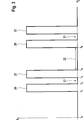
Es hat sich bei Versuchen mit Probanden herausgestellt, dass eine Rückstellkraft F in Form rechteckförmiger Kraftimpulse
In
Wenn sich das Fahrzeug in einem fahrdynamisch kritischen Zustand befindet oder wenn es die Verkehrssituation oder der Fahrzeugzustand erfordert, soll der Fahrzeugführer andererseits nicht abgelenkt werden und das Aufbringen der Kraftimpulse
Um den Fahrzeugführer effektiv auf einen empfohlenen Gangwechsel hinzuweisen ist es notwendig, die Reaktion des Fahrzeugführers innerhalb eines Nachlernalgorithmus zu analysieren. Der Nachlernalgorithmus ermittelt die Reaktion des Fahrzeugführers auf die aufgebrachte zusätzliche Rückstellkraft. Typische Fragestellungen sind dabei: Wie oft befolgt der Fahrzeugführer eine Gangwechselempfehlung und wie oft befolgt der Fahrzeugführer eine Gangwechselempfehlung nachdem er durch das erneute Aufbringen einer zusätzlichen Rückstellkraft erinnert wurde? Welche Reaktionszeit zwischen Gangwechselaufforderung und durchgeführtem Gangwechsel liegt vor?In order to effectively alert the driver to a recommended gearshift, it is necessary to have the driver's reaction analyze within a post-learning algorithm. The Nachlernalgorithmus determines the reaction of the driver to the applied additional restoring force. Typical questions include: How often does the driver follow a gear change recommendation and how often does the driver follow a gear change recommendation after having been reminded by reapplying an additional restoring force? What is the reaction time between gear change request and gear change?
Auf Grundlage des Reaktionsverhaltens des Fahrzeugführers verbessert der Nachlernalgorithmus das Aufbringen der zusätzlichen Rückstellkraft und verändert das Verhältnis von Kraftimpuls
Durch eine verbesserte Reaktion des Fahrzeugführers auf eine Aufforderung zum Gangwechsel wird der Verbrennungsmotor des Kraftfahrzeugs stets mit einem optimalen Wirkungsgrad betrieben und der Verbrauch an Kraftstoff und damit der Ausstoß an CO2 wird verringert.By an improved reaction of the driver to a request for gear change, the internal combustion engine of the motor vehicle is always operated with optimum efficiency and the consumption of fuel and thus the emission of CO 2 is reduced.
In
Bei der in
Die Profilwelle
Alternativ ist vorgesehen, dass die Drehbewegung der Profilwelle den Drehhebel
Die in
ZITATE ENTHALTEN IN DER BESCHREIBUNG QUOTES INCLUDE IN THE DESCRIPTION
Diese Liste der vom Anmelder aufgeführten Dokumente wurde automatisiert erzeugt und ist ausschließlich zur besseren Information des Lesers aufgenommen. Die Liste ist nicht Bestandteil der deutschen Patent- bzw. Gebrauchsmusteranmeldung. Das DPMA übernimmt keinerlei Haftung für etwaige Fehler oder Auslassungen.This list of the documents listed by the applicant has been generated automatically and is included solely for the better information of the reader. The list is not part of the German patent or utility model application. The DPMA assumes no liability for any errors or omissions.
Zitierte PatentliteraturCited patent literature
- WO 2007/073828 A1 [0002] WO 2007/073828 A1 [0002]
- DE 3232160 A1 [0003] DE 3232160 A1 [0003]
Claims (18)
Priority Applications (5)
| Application Number | Priority Date | Filing Date | Title |
|---|---|---|---|
| DE102009054650A DE102009054650A1 (en) | 2009-12-15 | 2009-12-15 | Device for generating an additional restoring force on the accelerator pedal and method for its operation |
| PCT/EP2010/066687 WO2011072943A1 (en) | 2009-12-15 | 2010-11-03 | Device for generating an additional reset force on a gas pedal and method for the operation thereof |
| EP10778951.3A EP2513525B1 (en) | 2009-12-15 | 2010-11-03 | Device for generating an additional reset force on a gas pedal and method for the operation thereof |
| US13/515,051 US8914210B2 (en) | 2009-12-15 | 2010-11-03 | Device for generating an additional reset force on a gas pedal and method for the operation thereof |
| JP2012543552A JP2013513756A (en) | 2009-12-15 | 2010-11-03 | Apparatus for generating additional reset force in an accelerator pedal and method for its operation |
Applications Claiming Priority (1)
| Application Number | Priority Date | Filing Date | Title |
|---|---|---|---|
| DE102009054650A DE102009054650A1 (en) | 2009-12-15 | 2009-12-15 | Device for generating an additional restoring force on the accelerator pedal and method for its operation |
Publications (1)
| Publication Number | Publication Date |
|---|---|
| DE102009054650A1 true DE102009054650A1 (en) | 2011-06-16 |
Family
ID=43513989
Family Applications (1)
| Application Number | Title | Priority Date | Filing Date |
|---|---|---|---|
| DE102009054650A Withdrawn DE102009054650A1 (en) | 2009-12-15 | 2009-12-15 | Device for generating an additional restoring force on the accelerator pedal and method for its operation |
Country Status (5)
| Country | Link |
|---|---|
| US (1) | US8914210B2 (en) |
| EP (1) | EP2513525B1 (en) |
| JP (1) | JP2013513756A (en) |
| DE (1) | DE102009054650A1 (en) |
| WO (1) | WO2011072943A1 (en) |
Cited By (5)
| Publication number | Priority date | Publication date | Assignee | Title |
|---|---|---|---|---|
| CN103213501A (en) * | 2012-01-20 | 2013-07-24 | 陈广林 | Automobile oil circuit clutch |
| DE102015208086A1 (en) | 2015-04-30 | 2016-11-03 | Continental Automotive Gmbh | A method for signaling a gear change recommendation to the driver of a motor vehicle |
| DE102015212499A1 (en) | 2015-07-03 | 2017-01-05 | Continental Automotive Gmbh | Method for operating an accelerator pedal with an actuator for generating a haptic signal |
| WO2017186413A1 (en) * | 2016-04-28 | 2017-11-02 | Audi Ag | Vehicle having an automatic transmission |
| DE102018207799A1 (en) * | 2018-05-17 | 2019-11-21 | Continental Automotive Gmbh | Control unit for pedal system and pedal system |
Families Citing this family (11)
| Publication number | Priority date | Publication date | Assignee | Title |
|---|---|---|---|---|
| US8836493B2 (en) * | 2010-12-30 | 2014-09-16 | Williams Controls, Inc. | Haptic pedal system |
| WO2012169477A1 (en) * | 2011-06-10 | 2012-12-13 | MINAMI Heiji | Accelerator pedal operation error resolution device |
| US9110490B2 (en) * | 2011-08-31 | 2015-08-18 | Ksr Ip Holdings Llc. | Floor mount ETC pedal with integrated kickdown and tactile alert mechanisms |
| DE102013209370A1 (en) * | 2012-05-22 | 2013-11-28 | Conti Temic Microelectronic Gmbh | Accelerator pedal unit for motor vehicles |
| KR101406533B1 (en) * | 2013-04-16 | 2014-06-12 | 기아자동차주식회사 | Active control method of accelerator pedal effort |
| DE102013213050A1 (en) | 2013-07-04 | 2015-01-08 | Conti Temic Microelectronic Gmbh | Accellerator Force Feedback Pedal (AFFP) as an assistance system for distance control in road traffic |
| DE102015109810A1 (en) * | 2015-06-19 | 2016-12-22 | Hella Kgaa Hueck & Co. | Accelerator pedal unit for a motor vehicle |
| JP6761323B2 (en) * | 2016-10-31 | 2020-09-23 | 修一 田山 | Accelerator pedal device for vehicles |
| US10214104B1 (en) * | 2017-11-28 | 2019-02-26 | Ford Global Technologies, Llc | Accelerator pedal for vehicle incorporating liquid nanofoam |
| CN108372784A (en) * | 2017-12-25 | 2018-08-07 | 朝阳聚声泰(信丰)科技有限公司 | It is anti-riot to rush accelerator pedal of automobile assembly |
| CN108454401A (en) * | 2018-04-18 | 2018-08-28 | 单萍 | A kind of buffer unit for preventing from stepping on pilot valve |
Citations (10)
| Publication number | Priority date | Publication date | Assignee | Title |
|---|---|---|---|---|
| DE3232160A1 (en) | 1982-08-30 | 1984-03-01 | Battelle-Institut E.V., 6000 Frankfurt | Process and arrangement for transferring information to drivers of motor vehicles |
| DE10210130A1 (en) * | 2002-03-08 | 2003-09-18 | Bosch Gmbh Robert | Driver warning, especially for warning of driving errors or impending potential hazards, involves generating warning signal with magnitude dependent on degree of driver inattentiveness |
| DE10250456A1 (en) * | 2001-11-05 | 2004-02-19 | Continental Teves Ag & Co. Ohg | Device with additional restoring force on the gas pedal depending on the setpoint deviation of a vehicle parameter |
| DE102004002179A1 (en) * | 2004-01-15 | 2005-08-11 | Volkswagen Ag | Vehicle fuel consumption optimization system generating a force signal dependent on fuel consumption and acceleration pedal position |
| WO2007073828A1 (en) | 2005-12-16 | 2007-07-05 | Bayerische Motoren Werke Aktiengesellschaft | Shifting point display in a motor vehicle comprising a manual transmission |
| EP1534554B1 (en) * | 2002-09-04 | 2007-07-11 | Siemens Aktiengesellschaft | Drive train of a motor vehicle and method for controllng a drive train |
| DE102007032722A1 (en) * | 2007-07-13 | 2008-02-28 | Daimler Ag | Motor vehicle operation optimizing method for accelerator pedal device, involves transmitting haptic drive instruction to driver to optimize preset operating value of vehicle, considering acceleration desire of driver as operating parameter |
| DE102007008275A1 (en) * | 2007-02-20 | 2008-08-21 | Bayerische Motoren Werke Aktiengesellschaft | Method for signaling operating gear change process by driver of vehicle by haptic noticeable signal, involves balancing drive train of vehicle for predetermined time period for signaling |
| DE102008060502A1 (en) * | 2007-12-15 | 2009-06-18 | Hyundai Motor Co. | Standing accelerator pedal assembly |
| DE102008064023A1 (en) * | 2008-12-19 | 2009-09-17 | Daimler Ag | Current operating point displaying method for motor vehicle, involves representing current operating point on display unit in connection with engine efficiency ranges that are represented differently according to corresponding evaluation |
Family Cites Families (23)
| Publication number | Priority date | Publication date | Assignee | Title |
|---|---|---|---|---|
| JPH0623023B2 (en) * | 1984-01-30 | 1994-03-30 | 富士重工業株式会社 | Control device for electromagnetic clutch for vehicle |
| US4998520A (en) * | 1990-05-11 | 1991-03-12 | Siemens Automotive L.P. | Redundant reset for electronic throttle control |
| FR2685667B1 (en) * | 1991-12-26 | 1994-07-29 | Landerretche Alain | ASSISTANCE DEVICE FOR CONTROLLING THE POWER OF VEHICLES EQUIPPED WITH AN INTERNAL COMBUSTION ENGINE. |
| DE19751520C1 (en) * | 1997-11-21 | 1999-10-28 | Bosch Gmbh Robert | Accelerator pedal module |
| DE10122162B4 (en) * | 2001-05-08 | 2015-07-16 | Volkswagen Ag | Method for controlling an automated step change gear and accelerator pedal device |
| JP4390560B2 (en) * | 2001-11-05 | 2009-12-24 | コンティネンタル・テーベス・アクチエンゲゼルシヤフト・ウント・コンパニー・オッフェネ・ハンデルスゲゼルシヤフト | Device with an additional return force of the accelerator pedal depending on the target value deviation of the vehicle parameter |
| US7166133B2 (en) * | 2002-06-13 | 2007-01-23 | Kensey Nash Corporation | Devices and methods for treating defects in the tissue of a living being |
| JP4254501B2 (en) * | 2003-11-20 | 2009-04-15 | 日産自動車株式会社 | VEHICLE DRIVE OPERATION ASSISTANCE DEVICE AND VEHICLE HAVING VEHICLE DRIVE OPERATION ASSISTANCE DEVICE |
| DE102004002114B4 (en) * | 2004-01-14 | 2006-06-01 | Ab Elektronik Gmbh | Accelerator pedal unit with force jump element |
| JP4367180B2 (en) * | 2004-03-03 | 2009-11-18 | 日産自動車株式会社 | VEHICLE DRIVE OPERATION ASSISTANCE DEVICE AND VEHICLE PROVIDED WITH VEHICLE DRIVE OPERATION ASSISTANCE DEVICE |
| DE102004024763B4 (en) * | 2004-05-17 | 2006-05-24 | Ab Elektronik Gmbh | Pedal unit for motor vehicle, has drive lever pivotably mounted on pedal member, and moving member which acts on operating lever |
| DE102004026407B4 (en) * | 2004-05-29 | 2010-06-24 | Bayerische Motoren Werke Aktiengesellschaft | Method for controlling an adjustable restoring force on an accelerator pedal in a vehicle |
| DE102004027610A1 (en) * | 2004-06-05 | 2006-01-05 | Ab Elektronik Gmbh | Pedal unit and pedal assembly for motor vehicle |
| JP4367319B2 (en) * | 2004-11-12 | 2009-11-18 | 日産自動車株式会社 | VEHICLE DRIVE OPERATION ASSISTANCE DEVICE AND VEHICLE HAVING VEHICLE DRIVE OPERATION ASSISTANCE DEVICE |
| JP2006176001A (en) * | 2004-12-22 | 2006-07-06 | Toyota Motor Corp | Pedal reaction control device |
| JP2007022396A (en) * | 2005-07-19 | 2007-02-01 | Toyota Motor Corp | Pedal device for vehicle |
| JP5056185B2 (en) * | 2007-06-12 | 2012-10-24 | 日産自動車株式会社 | Vehicle shift guide device |
| DE102007035426A1 (en) | 2007-07-28 | 2009-01-29 | Dr. Ing. H.C. F. Porsche Aktiengesellschaft | Motor vehicle, display device and operating method |
| US7699129B2 (en) * | 2007-10-31 | 2010-04-20 | Ford Global Technologies, Llc | Method and system for alerting a driver that a motive power system is about to be activated |
| DE102008038808A1 (en) * | 2008-08-13 | 2010-02-25 | Zf Friedrichshafen Ag | Fußpedalmodul |
| EP2451688A1 (en) * | 2009-07-09 | 2012-05-16 | Conti Temic Microelectronic GmbH | Device for generating an additional restoring force at the gas pedal and method for the operation thereof |
| JP5466086B2 (en) * | 2010-06-04 | 2014-04-09 | 株式会社ミクニ | Accelerator pedal device |
| DE102011079375A1 (en) * | 2010-10-06 | 2012-04-12 | Conti Temic Microelectronic Gmbh | Method for operating an accelerator pedal unit for motor vehicles |
-
2009
- 2009-12-15 DE DE102009054650A patent/DE102009054650A1/en not_active Withdrawn
-
2010
- 2010-11-03 WO PCT/EP2010/066687 patent/WO2011072943A1/en active Application Filing
- 2010-11-03 EP EP10778951.3A patent/EP2513525B1/en not_active Not-in-force
- 2010-11-03 JP JP2012543552A patent/JP2013513756A/en active Pending
- 2010-11-03 US US13/515,051 patent/US8914210B2/en not_active Expired - Fee Related
Patent Citations (10)
| Publication number | Priority date | Publication date | Assignee | Title |
|---|---|---|---|---|
| DE3232160A1 (en) | 1982-08-30 | 1984-03-01 | Battelle-Institut E.V., 6000 Frankfurt | Process and arrangement for transferring information to drivers of motor vehicles |
| DE10250456A1 (en) * | 2001-11-05 | 2004-02-19 | Continental Teves Ag & Co. Ohg | Device with additional restoring force on the gas pedal depending on the setpoint deviation of a vehicle parameter |
| DE10210130A1 (en) * | 2002-03-08 | 2003-09-18 | Bosch Gmbh Robert | Driver warning, especially for warning of driving errors or impending potential hazards, involves generating warning signal with magnitude dependent on degree of driver inattentiveness |
| EP1534554B1 (en) * | 2002-09-04 | 2007-07-11 | Siemens Aktiengesellschaft | Drive train of a motor vehicle and method for controllng a drive train |
| DE102004002179A1 (en) * | 2004-01-15 | 2005-08-11 | Volkswagen Ag | Vehicle fuel consumption optimization system generating a force signal dependent on fuel consumption and acceleration pedal position |
| WO2007073828A1 (en) | 2005-12-16 | 2007-07-05 | Bayerische Motoren Werke Aktiengesellschaft | Shifting point display in a motor vehicle comprising a manual transmission |
| DE102007008275A1 (en) * | 2007-02-20 | 2008-08-21 | Bayerische Motoren Werke Aktiengesellschaft | Method for signaling operating gear change process by driver of vehicle by haptic noticeable signal, involves balancing drive train of vehicle for predetermined time period for signaling |
| DE102007032722A1 (en) * | 2007-07-13 | 2008-02-28 | Daimler Ag | Motor vehicle operation optimizing method for accelerator pedal device, involves transmitting haptic drive instruction to driver to optimize preset operating value of vehicle, considering acceleration desire of driver as operating parameter |
| DE102008060502A1 (en) * | 2007-12-15 | 2009-06-18 | Hyundai Motor Co. | Standing accelerator pedal assembly |
| DE102008064023A1 (en) * | 2008-12-19 | 2009-09-17 | Daimler Ag | Current operating point displaying method for motor vehicle, involves representing current operating point on display unit in connection with engine efficiency ranges that are represented differently according to corresponding evaluation |
Cited By (6)
| Publication number | Priority date | Publication date | Assignee | Title |
|---|---|---|---|---|
| CN103213501A (en) * | 2012-01-20 | 2013-07-24 | 陈广林 | Automobile oil circuit clutch |
| CN103213501B (en) * | 2012-01-20 | 2015-08-19 | 陈广林 | A kind of automobile oil circuit clutch |
| DE102015208086A1 (en) | 2015-04-30 | 2016-11-03 | Continental Automotive Gmbh | A method for signaling a gear change recommendation to the driver of a motor vehicle |
| DE102015212499A1 (en) | 2015-07-03 | 2017-01-05 | Continental Automotive Gmbh | Method for operating an accelerator pedal with an actuator for generating a haptic signal |
| WO2017186413A1 (en) * | 2016-04-28 | 2017-11-02 | Audi Ag | Vehicle having an automatic transmission |
| DE102018207799A1 (en) * | 2018-05-17 | 2019-11-21 | Continental Automotive Gmbh | Control unit for pedal system and pedal system |
Also Published As
| Publication number | Publication date |
|---|---|
| US20120279347A1 (en) | 2012-11-08 |
| US8914210B2 (en) | 2014-12-16 |
| EP2513525B1 (en) | 2013-10-30 |
| JP2013513756A (en) | 2013-04-22 |
| WO2011072943A1 (en) | 2011-06-23 |
| EP2513525A1 (en) | 2012-10-24 |
Similar Documents
| Publication | Publication Date | Title |
|---|---|---|
| EP2513525B1 (en) | Device for generating an additional reset force on a gas pedal and method for the operation thereof | |
| DE102009000919B4 (en) | Method for operating a motor-assisted pedal vehicle, in particular a bicycle, and a device for using the method and a pedal vehicle with this device | |
| DE102007021985B4 (en) | Accelerator system | |
| WO2009112102A1 (en) | Method and device for operating a hybrid vehicle | |
| DE102007001362A1 (en) | Method and device for driver fatigue detection by means of torque sensors | |
| WO2011072987A1 (en) | Drive train and method for operating the same | |
| EP1651494A1 (en) | Method for controlling an actuator of a starting clutch in the automatic transmission of a vehicle | |
| EP2790948B1 (en) | Haptic acceleration pedal for a motor vehicle having a resetting element associated with an actuator | |
| DE102006025339A1 (en) | Pedal for motor vehicle, has device for generating vibration, which is generated in x, y level perpendicular to z-direction | |
| WO2009047162A1 (en) | Method for generating braking torque in motor vehicles with a double clutch transmission | |
| DE102012221896B4 (en) | Method for determining a contact point of a friction clutch | |
| WO2016202335A1 (en) | Accelerator pedal for controlling a driving engine of a motor vehicle, with an adjustable zero point position | |
| DE102010042895A1 (en) | Adjustment device for power control of an internal combustion engine and method for power control of the internal combustion engine | |
| DE10306100C5 (en) | Motor vehicle with a steering system comprising a mechanical steering column including steering wheel and a system for detecting a deviation of the lane of the motor vehicle from an excellent lane of the road or for detecting an occupancy of a neighboring lane | |
| EP2193061B1 (en) | Method and device for influencing the traction force during shifting operations of a manual transmission in vehicles | |
| EP3012144B1 (en) | Method for controlling an adjustable reset force on a driving pedal of a commercial vehicle | |
| DE102010039377A1 (en) | Method for operating drive train of motor vehicle, involves announcing initial start of internal combustion engine with help of electrical machine by assembling counter pressure at accelerator pedal | |
| DE102008026729A1 (en) | Electromechanical steering mechanism for passenger motor vehicle, has control unit activating generation unit at defined time interval during determination of functional interruption for generating sensible excitation of steering wheel | |
| WO2003086806A1 (en) | Control device and method for controlling engine torque and clutch torque in a drive train | |
| EP2790945B1 (en) | Method and control device for controlling a haptic acceleration pedal that is to be set in oscillation in a motor vehicle | |
| DE102004002179A1 (en) | Vehicle fuel consumption optimization system generating a force signal dependent on fuel consumption and acceleration pedal position | |
| DE102014226851A1 (en) | Actuating device for a clutch of a motor vehicle and clutch with a corresponding actuator | |
| DE102015219554B4 (en) | Method and control device for determining a braking force or a variable corresponding to the braking force | |
| DE19802736A1 (en) | Car power plant with engine connected mechanically via clutch to gearbox | |
| DE102016217281A1 (en) | Method for operating a drive train |
Legal Events
| Date | Code | Title | Description |
|---|---|---|---|
| OM8 | Search report available as to paragraph 43 lit. 1 sentence 1 patent law | ||
| R119 | Application deemed withdrawn, or ip right lapsed, due to non-payment of renewal fee |