EP2243453B1 - Work chair - Google Patents
Work chair Download PDFInfo
- Publication number
- EP2243453B1 EP2243453B1 EP09158289A EP09158289A EP2243453B1 EP 2243453 B1 EP2243453 B1 EP 2243453B1 EP 09158289 A EP09158289 A EP 09158289A EP 09158289 A EP09158289 A EP 09158289A EP 2243453 B1 EP2243453 B1 EP 2243453B1
- Authority
- EP
- European Patent Office
- Prior art keywords
- work chair
- drive wheels
- support wheel
- wheels
- chair according
- Prior art date
- Legal status (The legal status is an assumption and is not a legal conclusion. Google has not performed a legal analysis and makes no representation as to the accuracy of the status listed.)
- Not-in-force
Links
Images


Classifications
-
- A—HUMAN NECESSITIES
- A61—MEDICAL OR VETERINARY SCIENCE; HYGIENE
- A61G—TRANSPORT, PERSONAL CONVEYANCES, OR ACCOMMODATION SPECIALLY ADAPTED FOR PATIENTS OR DISABLED PERSONS; OPERATING TABLES OR CHAIRS; CHAIRS FOR DENTISTRY; FUNERAL DEVICES
- A61G5/00—Chairs or personal conveyances specially adapted for patients or disabled persons, e.g. wheelchairs
- A61G5/10—Parts, details or accessories
- A61G5/1056—Arrangements for adjusting the seat
- A61G5/1059—Arrangements for adjusting the seat adjusting the height of the seat
-
- A—HUMAN NECESSITIES
- A61—MEDICAL OR VETERINARY SCIENCE; HYGIENE
- A61G—TRANSPORT, PERSONAL CONVEYANCES, OR ACCOMMODATION SPECIALLY ADAPTED FOR PATIENTS OR DISABLED PERSONS; OPERATING TABLES OR CHAIRS; CHAIRS FOR DENTISTRY; FUNERAL DEVICES
- A61G5/00—Chairs or personal conveyances specially adapted for patients or disabled persons, e.g. wheelchairs
- A61G5/10—Parts, details or accessories
- A61G5/1005—Wheelchairs having brakes
- A61G5/101—Wheelchairs having brakes of the parking brake type, e.g. holding the wheelchair
-
- A—HUMAN NECESSITIES
- A61—MEDICAL OR VETERINARY SCIENCE; HYGIENE
- A61G—TRANSPORT, PERSONAL CONVEYANCES, OR ACCOMMODATION SPECIALLY ADAPTED FOR PATIENTS OR DISABLED PERSONS; OPERATING TABLES OR CHAIRS; CHAIRS FOR DENTISTRY; FUNERAL DEVICES
- A61G5/00—Chairs or personal conveyances specially adapted for patients or disabled persons, e.g. wheelchairs
- A61G5/10—Parts, details or accessories
- A61G5/1005—Wheelchairs having brakes
- A61G5/1013—Wheelchairs having brakes engaging the wheel
- A61G5/1018—Wheelchairs having brakes engaging the wheel on the running surface
-
- A—HUMAN NECESSITIES
- A61—MEDICAL OR VETERINARY SCIENCE; HYGIENE
- A61G—TRANSPORT, PERSONAL CONVEYANCES, OR ACCOMMODATION SPECIALLY ADAPTED FOR PATIENTS OR DISABLED PERSONS; OPERATING TABLES OR CHAIRS; CHAIRS FOR DENTISTRY; FUNERAL DEVICES
- A61G5/00—Chairs or personal conveyances specially adapted for patients or disabled persons, e.g. wheelchairs
- A61G5/10—Parts, details or accessories
- A61G5/1005—Wheelchairs having brakes
- A61G5/1029—Wheelchairs having brakes engaging a surface, e.g. floor or wall
-
- A—HUMAN NECESSITIES
- A61—MEDICAL OR VETERINARY SCIENCE; HYGIENE
- A61G—TRANSPORT, PERSONAL CONVEYANCES, OR ACCOMMODATION SPECIALLY ADAPTED FOR PATIENTS OR DISABLED PERSONS; OPERATING TABLES OR CHAIRS; CHAIRS FOR DENTISTRY; FUNERAL DEVICES
- A61G5/00—Chairs or personal conveyances specially adapted for patients or disabled persons, e.g. wheelchairs
- A61G5/10—Parts, details or accessories
- A61G5/1054—Large wheels, e.g. higher than the seat portion
-
- A—HUMAN NECESSITIES
- A61—MEDICAL OR VETERINARY SCIENCE; HYGIENE
- A61G—TRANSPORT, PERSONAL CONVEYANCES, OR ACCOMMODATION SPECIALLY ADAPTED FOR PATIENTS OR DISABLED PERSONS; OPERATING TABLES OR CHAIRS; CHAIRS FOR DENTISTRY; FUNERAL DEVICES
- A61G5/00—Chairs or personal conveyances specially adapted for patients or disabled persons, e.g. wheelchairs
- A61G5/10—Parts, details or accessories
- A61G5/1086—Anti-roll-back devices
-
- A—HUMAN NECESSITIES
- A61—MEDICAL OR VETERINARY SCIENCE; HYGIENE
- A61G—TRANSPORT, PERSONAL CONVEYANCES, OR ACCOMMODATION SPECIALLY ADAPTED FOR PATIENTS OR DISABLED PERSONS; OPERATING TABLES OR CHAIRS; CHAIRS FOR DENTISTRY; FUNERAL DEVICES
- A61G5/00—Chairs or personal conveyances specially adapted for patients or disabled persons, e.g. wheelchairs
- A61G5/10—Parts, details or accessories
- A61G5/1089—Anti-tip devices
-
- A—HUMAN NECESSITIES
- A61—MEDICAL OR VETERINARY SCIENCE; HYGIENE
- A61G—TRANSPORT, PERSONAL CONVEYANCES, OR ACCOMMODATION SPECIALLY ADAPTED FOR PATIENTS OR DISABLED PERSONS; OPERATING TABLES OR CHAIRS; CHAIRS FOR DENTISTRY; FUNERAL DEVICES
- A61G5/00—Chairs or personal conveyances specially adapted for patients or disabled persons, e.g. wheelchairs
- A61G5/10—Parts, details or accessories
- A61G5/104—Devices for lifting or tilting the whole wheelchair
Landscapes
- Health & Medical Sciences (AREA)
- Life Sciences & Earth Sciences (AREA)
- Animal Behavior & Ethology (AREA)
- General Health & Medical Sciences (AREA)
- Public Health (AREA)
- Veterinary Medicine (AREA)
- Handcart (AREA)
- Special Chairs (AREA)
Abstract
Description
- The invention relates generally to work chairs for disabled persons.
- Wheel chairs known in the art are adapted to enable a physically disabled person to travel considerable distances at relatively high speeds. For this purpose, wheelchairs are designed to place the person in an optimal position for operating the drive wheels with the arms. Furthermore, to get the required balance to travel at relatively high speeds, the center of gravity of the person should be placed close to the rotational axis of the drive wheels, which gives the wheelchair a design which places the person in a low seating, relative to office and dining tables. The wheel chairs of the art furthermore have a relatively large footprint for providing the desired stability of the wheelchair. In an office or dining setting this create problems, which usually requires special adaptations of a room in which a disabled person should work.
- Office chairs of the art typically have a wheeled base with a relatively small footprint, preferably not extending to far outside of the radius of the seat. The construction enables the person sitting in the office chair to travel short distances in an office without being confined by the furniture of the room. An office chair of the art could furthermore comprise a telescopic gas cylinder allowing a person to adjust the height of the chair to suit the office table. Another aspect of the height adjustment is that it enables the person to alternate between different seating height, which alleviates the back, neck and legs of strains arising from uniform seating. The wheeled base of an office chair preferably comprises swiveling casters which are rotatable around a vertical axis, an addition to the wheels of the casters rolling in the direction of travel. The caster wheel base allows the office chair to be movable in all directions and thus create an optimal desired position of the chair in relation to the office furniture or desired operating position. Office chairs generally have a stiff base part to which the wheels are attached. The fixed base part construction limits the chairs ability to overcome obstacles such as thresholds and uneven ground surfaces.
- In
US patent application 2007/0216131 , Potappel discloses a wheelchair provided with swiveling casters for use in an office environment. The wheelchair of Potappel has two forward support wheels, preferably casters, which are fixedly attached to a base member, to which the drive wheels of the wheel chair are attached as well. Furthermore the wheelchair comprises two rearward support wheels, preferably casters, which are pivotally mounted to the base part for enabling the person using the chair to travel over obstacles. The pivotally mounted rearward support wheel allows the wheelchair to rock in a length axis of the wheelchair, the same distance as the rearward support wheel is pivotal. Hence, this construction does not provide the stable behavior desired in an office chair. Potappel further discloses that the drive wheels of the wheelchair can be provided with breaks, which requires the drive wheels to be of a material providing high friction against the ground surface for providing adequate breaking power, this limits the ability to adapt the material of the wheels to the material of the ground surface. - A work chair as claimed in claim 1 is provided. The work chair comprises at least one rearward support wheel, at least one forward support wheel, at least two drive wheels and a height adjustable seat. The work chair further comprises a bogie base member. One of the at least two drive wheels are rotatably fixated to the bogie base member at a first fixation point, one of: a rearward support wheel and a forward support wheel are rotatably fixated to the bogie base member, at a second fixation point, and the bogie base member is adapted to have a pivot axis substantially between the first fixation point and the second fixation point. The pivot axis enables the wheels of the work chair to stay in contact with the ground surface, even when traveling over uneven surfaces.
- According to one embodiment the work chair further comprises a break member adapted to engage the ground surface for providing a stable position for the work chair. The break member could comprise a material different from the materials of the at least one rearward support wheel, the at least one forward support wheel, and/or the at least two drive wheels for having a brake member with a higher friction against the ground surface than the friction created between the wheels and the ground surface. The brake member could be adapted to be operable, e.g. using a force selected from a list consisting of: mechanical force, hydraulic force and pneumatic force.
- The work chair according to any of the embodiments above could comprise a height adjustable seat, which could be an electrically height adjustable seat enabling a disabled person to adjust the height of the seat to adapt the work chair to its surroundings.
- For enabling the work chair according to any one of the embodiments to move in multiple directions, the at least one rearward support wheel, and the at least one forward support wheel could be a swiveling castor.
- The work chair according to any of the embodiments could further comprise a lifting device adapted to lift the drive wheels to a point at which the drive wheels do not engage the ground surface. This enables the work chair to be moved in a sideways direction. The lifting device could be a manual lifting device, such as a manual mechanical lifting device, according to one embodiment the lifting device is an electrically powered lifting device, which could be selected from a group consisting of: pneumatic lifting devices, hydraulic lifting devices and mechanical lifting devices.
- For manually propelling the drive wheels, the diameter of the drive wheels could be larger than the diameter of the support wheels, according to one embodiment the diameter of the drive wheels is at least two times as large as the diameter of the support wheels, and according to another embodiment the diameter of the drive wheels is at least four times as large as the diameter of the support wheels.
- The invention is now described, by way of example, with reference to the accompanying drawings, in which:
-
Fig. 1 shows the work chair in a side view, according to a first embodiment. -
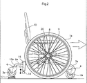
Fig. 2 shows the work chair in a side view, according to the first embodiment, when traveling over an uneven surface. -
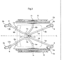
Fig. 3 shows the work chair, according to the first embodiment, from above. -
Fig. 4 shows the work chair in a side view, according to a second embodiment. -
Fig. 5 shows the work chair, according to the second embodiment, from above. - A bogie is to be understood as a chassis or framework adapted to carry wheels and having a pivot axis.
- A bogie base member is to be understood as a part of the bogie construction to which the wheels are directly or indirectly mounted.
- A rearward support wheel is to be understood as a wheel having its axis of rotation behind the axis of rotation of the drive wheels, in the normal direction of operation of a chair having drive wheels.
- A forward support wheel is to be understood as a wheel having its axis of rotation in front of the axis of rotation of the drive wheels, in the normal direction of operation of a chair having drive wheels.
- A drive wheel is to be understood as a wheel which at least at times engages the ground surface with the purpose of propelling the device to which the drive wheel is attached.
- In the following a detailed description of preferred embodiments of the present invention will be given. In the drawing figures, like reference numerals designate identical or corresponding elements throughout the several figures. It will be appreciated that these figures are for illustration only and are not in any way restricting the scope of the invention. Thus, any references to direction, such as "up" or "down", are only referring to the directions shown in the figures. Also, any dimensions etc. shown in the figures are for illustration purposes.
-
Fig. 1 shows a work chair according to an embodiment in which the work chair comprises tworearward support wheels 3a,b, twoforward support wheels 2a,b and twodrive wheels 1a,b. The twodrive wheels 1a,b are rotatably fixated to abogie base member 6a,b at afirst fixation point 7a,b and are adapted for manual propulsion through the user engaging themanual propulsion bars 8 fixated to thedrive wheels 1a,b along the circumference thereof. - The two
rearward support wheels 3a,b are rotatably fixated to thebogie base members 6a,b at asecond fixation point 12a,b and are, according to the embodiment offig.1 , rearwardsupport wheels 3a,b of the swiveling castor type. Thebogie base member 6a is pivotally mounted at apivot axis 16 located between thefirst fixation point 7a,b and thesecond fixation point 12a,b. Thefirst fixation point 7a,b is thus located in front of thepivot axis 16 fixating thebogie base member 6a,b to the work chair and thesecond fixation point 12a,b is located in behind thepivot axis 16. - The
forward support wheels 2a,b are rotatably fixated toforward support bars 5a,b which are parts of aforward support assembly 19 fixedly attached to a base part of the work chair. According to this embodiment, theforward support wheels 2a,b are of the swiveling castor type. The forward 2a,b and rearward 3a,b support wheels being of the swiveling castor type enables the support wheels to rotate around acastor axis 4 extending in a vertical up-down direction, down being in the direction of the ground surface and up being the opposite direction. The rotation around thiscastor axis 16 enables the work chair to rotate on the area of its footprint, thus rotating around a point placed in the middle of the twodrive wheels 1a,b. Thesupport wheels 2a,b, 3a,b being of the swiveling castor type also enables the user to freely move around the work chair, for example by trippling the work chair with the legs, e.g. when the users hand are occupied, or by moving the work chair by pushing or pulling objects of the room using the arms. - The forward 2a,b and rearward 3a,b support wheels are preferably positioned to provide sufficient support to create a stable work chair for the user without the chair getting a far too large over-all footprint limiting the user from moving around in an office or dining setting.
- The work chair according to the embodiment shown in
fig. 1 further comprises a heightadjustable seat 9 comprising aback rest 10. The heightadjustable seat 9 is height adjustable by means of aheight adjustment cylinder 11 fixated to the base part of the work chair. Theheight adjustment cylinder 11 could be operable using mechanical force, hydraulic force and pneumatic force. According to the embodiment shown infig. 1 theheight adjustment cylinder 11 is a gas filled cylinder, as is known from most office chairs of the art, which is controllably connected to acontrol assembly 20 trough aconnection line 15. The control assembly is positioned in connection to theseat 9 such that thecontrol assembly 20 is easily accessible to the user. According to other embodiments (not shown) theheight adjustment cylinder 11 is electrically powered, which enables less mobile users to operate the height adjustment function without having to deliver a large force, e.g. by operating an electrical switch. Adjusting the height of the work chair could be advantageous as the optimal position for traveling in the work chair using manual propulsion of the drive wheels are much lower than the optimal position in an office or dining setting. When traveling in the chair it could be advantageous to have a center of gravity close to thefixation points 7a,b of thedrive wheels 1a,b, since this puts the user in a balanced position in the work chair. The height adjustment of theseat 9 further enables the user to easily adapt to tables of different height, which further reduces the need for adaptation of additional furniture. According to one embodiment the height adjustable seat is rotatable in accordance with most office chairs of the art. - The work chair of
fig. 1 further comprises abreak member 13 adapted to engage the ground surface. Thebreak member 13 can be operable using mechanical force, hydraulic force or pneumatic force, in the embodiment shown infig. 1 thebreak member 13 comprises a pneumatic cylinder operably connected to thesame control assembly 20 as theheight adjustment cylinder 11. However it is equally conceivable that the pneumatic cylinder operating the break is controlled from a separate control assembly (not shown). Infig. 1 thebreak member 13 is shown in the state in which thebreak member 13 engages the ground floor and thus breaks the work chair in relation to the ground surface. Thedrive wheels 1a,b and thesupport wheels 2a,b, 3a,b, could have a ground surface contacting layer which is adapted to the material of the ground surface, such as a harder surface contacting layer for softer ground surface materials and a softer surface contacting layer for harder ground surface materials. The adaptation in materials could lead to that the friction, between the ground surface and the wheels, is too low for using the wheels as breaks. The groundsurface contacting part 14 of thebreak member 13 could therefore comprise a material different from the material of the wheels for creating suitable friction between the contactingpart 14 and the ground surface. However in other embodiments (shown infigs. 4 and5 ) the brakes engages the wheels, particularly the drive wheels, whereby thedrive wheels 1a,b acts as break members contacting the ground surface. - To enable the manual propulsion of the
drive wheels 1a,b in a comfortable way, thedrive wheels 1a,b should be made with a larger diameter than thesupport wheels 2a,b 3a,b. According to one embodiment the diameter of thedrive wheels 1a,b is at least two times as large as the diameter of thesupport wheels 2a,b; 3a,b and according to another embodiment the diameter of thedrive wheels 1a,b is at least four times as large as the diameter of thesupport wheels 2a,b; 3a,b. -
Fig. 2 shows the work chair according to the embodiment offig.1 when the work chair travels over athreshold 17 by manual propulsion of thedrive wheels 1a,b rotatably fixated to thebogie base members 6a,b, which in turn is pivotally mounted to the work chair. When thethreshold 17 raises therearward support wheels 3a,b thebogie base members 6a,b pivots around thepivot axis 16 keeping thedrive wheel 1a in contact with the ground surface at all times and thus enables the user to further propel the work chair for continued advancement. - The
brake member 13 is here shown in the state in which thebrake member 13 does not engage the ground surface and thus do not hinder the work chair from moving. - According to another embodiment (not shown) at least one
forward support wheel 2a,b and thedrive wheels 1a,b are rotatably fixated to a pivotally mountedbogie base member 6a,b, whereas at least onerearward support wheel 3a,b is fixedly attached to the work chair. This embodiment also fulfills the main purpose of maintaining the contact between the ground surface and wheels, even when traveling over uneven surfaces. It is also conceivable that both the front and rear support wheels are rotatably fixated to a pivotally mounted bogie base member. -
Fig. 3 shows the work chair from above showing therearward support wheels 3a,b being rotatably fixated to thecastor axis 4 enabling thesupport wheels 2a,b; 3a,b to rotate around thecastor axis 4 extending in a vertical up-down direction. Thecastor axis 4 in turn being fixated to the rear part of thebogie base member 6a,b in asecond point 12a,b. Thebrake members 13 are also fixated to the rear part of theboogie base member 6a,b. Thedrive wheels 1a,b are rotatably fixated to afirst point 7a,b of the forward part of thebogie base member 6a,b. Thebogie base member 6a,b being pivotally mounted at apivot axis 16 which extends through a bearinghousing 21 which contains the bearings making thepivot axis 16 operable. According to the embodiment shown, the right 6a and left 6b bogie base members are mounted to thesame pivot axis 16 interconnecting the movements of the twobogie base members 6a,b. However, according to other embodiments the right 6a and left 6b bogie base members could be connected to a right and left pivot axis and thus individually operable. It could be advantageous for the forward part of thebogie base member 6a,b comprising thedrive wheels 1a,b to extend a shorter distance from thepivot axis 16 in a length axis L of the work chair than the rearward part of thebogie base members 6a,b comprising therearward support wheels 3a,b, since the elevation of thesupport wheels 3a,b then does not elevate the base part of the work chair as much, and thus the user. -
Fig. 3 further shows theforward support assembly 19 fixedly attached to a base part of the work chair. Theforward support assembly 19 comprises the twoforward support wheels 2a,b rotatably fixated to thecastor axis 4 enabling the support wheels to rotate around thecastor axis 4 extending in a vertical up-down direction. The base part of the work chair further comprises the heightadjustable cylinder 11 to which theseat 9 andbackrest 10 is height adjustably fixated. -
Fig. 4 shows the work chair according to another embodiment, in which the work chair further comprises a lifting device in form of anoperable cylinder 18 for raising thedrive wheels 1a,b above the ground surface through saidoperable cylinder 18 extending. The raising of thedrive wheels 1a,b enables the user to, by means of the support wheels being swiveling casters, e.g. move the work chair sideways which allows the user to better adjust the work chair in an office or dining setting. Theoperable cylinder 18 can be operable manually mechanical, manually pneumatic/hydraulic or electrically powered mechanically/pneumatic or hydraulic. According to the embodiment shown, theoperable cylinder 18 is connected to thecontrol assembly 20, however it is equally conceivable that theoperable cylinder 18 is connected to its own control assembly. According to one embodiment (not shown) the raisable drive wheels can be locked in a raised position by means of a locking member. - The
brake member 23 as shown infig. 4 is adapted to engage thedrive wheels 1a,b by means of an engagingmember 24 operably mounted to thebrake member 23. According to the embodiment shown, thebrake member 23 is connected to thecontrol assembly 20, however it is equally conceivable that thebrake member 23 is connected to its own control assembly. -
Fig. 5 shows the work chair from above showing therearward support wheels 3a,b being rotatably fixated to thecastor axis 4 enabling thesupport wheels 3a,b to rotate around thecastor axis 4 extending in a up-down direction. Thecastor axis 4 in turn being fixated to the rear part of thebogie base member 6a,b in asecond point 12a,b. Thebrake members 23 are also fixated to the rear part of theboogie base member 6a,b. Thedrive wheels 1a,b is rotatably fixated to afirst point 7a,b of the forward part of thebogie base member 6a,b. Thebogie base member 6a,b being pivotally fixated at apivot axis 16 which extends through a bearinghousing 21 which contains the bearings making thepivot axis 16 operable. Thebrake member 23 as shown infig. 5 is adapted to engage thedrive wheels 1a,b by means of an engagingmember 24 operably mounted to thebrake member 23. According to the embodiment shown, thebrake member 23 is connected to thecontrol assembly 20, however it is equally conceivable that thebrake member 23 is connected to its own control assembly. -
Fig. 5 further shows the operable cylinder also described infig. 4 for raising thedrive wheels 1a,b above the ground surface. Theoperable cylinder 18 is here fixated to asupport bar 25 fixated to the right 6a and left 6b bogie base members and to the heightadjustable cylinder 11 and thus, when extended, raises thedrive wheels 1a,b above the ground surface. - According to a further extension of the embodiments shown above the manually propelled
drive wheels 1a,b are assisted by an electrical motor, and according to one embodiment the work chair comprises two individual electrical motors in connection with each of the right 1a and left 1b drive wheels. - Please note that any embodiment or part of embodiment, feature, described herein may be combined in any way.
Claims (13)
- A work chair comprising:a. at least one first support wheel,b. at least one second support wheel,c. at least two drive wheels (1a,b), andd. a height adjustable seat (9) fixated to a base part, wherein said first or second support wheel is adapted to be a rearward support wheel (3a,b), and the other of said first and second support wheel is adapted to be a forward support wheel (2a,b), wherein said work chair further comprises a bogie base member (6a,b), characterized in thati. said at least two drive wheels (1a,b) are rotatably fixated to said bogie base member (6a,b), at a first fixation point,ii. said at least one first support wheel (3a,b) is rotatably fixated to said bogie base member (6a,b), at a second fixation point,iii. said at least one second support wheel is fixated to said base part, andiv. said bogie base member (6a,b) is adapted to have a pivot axis (16), fixating the bogie base member to the base part, substantially between said first fixation point and said second fixation point.
- The work chair according to claim 1, further comprising a break member (13) adapted to engage the ground surface.
- The work chair according to claim 2, wherein said break (13) member comprises a material different from the materials of said at least one rearward support wheel (3a,b), said at least one forward support wheel (2a,b), and said at least two drive wheels (1a,b).
- The work chair according to any one of claims 2 and 3, wherein said break member (13) is adapted to be operable.
- The work chair according to claim 4, wherein said operable break member (13) is adapted to be operable using a force selected from a list consisting of: mechanical force, hydraulic force and pneumatic force.
- The work chair according to any one of the preceding claims, wherein said height adjustable seat (9) is electrically height adjustable.
- The work chair according to any one of the preceding claims, wherein at least one of said at least one rearward support wheel (3a,b), and said at least one forward support wheel (2a,b), is a swiveling castor.
- The work chair according to any one of the preceding claims, further comprising a lifting device (18) adapted to lift the drive wheels (1a,b) to a point at which the drive wheels (1a,b) do not engage the ground surface.
- The work chair according to claim 8, wherein said lifting device (18) is an electrically powered lifting device.
- The work chair according to claim 8, wherein said lifting device (18) is a lifting device selected from a group consisting of: pneumatic lifting devices, hydraulic lifting devices and mechanical lifting devices.
- The work chair according to any one of the preceding claims, wherein the diameter of said drive wheels (1a,b) is larger than the diameter of said support wheels (2a,b; 3a,b).
- The work chair according to claim 12, wherein the diameter of said drive wheels (1a,b) is at least 2 times as large as the diameter of said support wheels (2a,b; 3a,b).
- The work chair according to claim 12, wherein the diameter of said drive wheels (1a,b) is at least 4 times as large as the diameter of said support wheels (2a,b; 3a,b).
Priority Applications (2)
| Application Number | Priority Date | Filing Date | Title |
|---|---|---|---|
| EP09158289A EP2243453B1 (en) | 2009-04-20 | 2009-04-20 | Work chair |
| AT09158289T ATE537802T1 (en) | 2009-04-20 | 2009-04-20 | WORK CHAIR |
Applications Claiming Priority (1)
| Application Number | Priority Date | Filing Date | Title |
|---|---|---|---|
| EP09158289A EP2243453B1 (en) | 2009-04-20 | 2009-04-20 | Work chair |
Publications (2)
| Publication Number | Publication Date |
|---|---|
| EP2243453A1 EP2243453A1 (en) | 2010-10-27 |
| EP2243453B1 true EP2243453B1 (en) | 2011-12-21 |
Family
ID=41011931
Family Applications (1)
| Application Number | Title | Priority Date | Filing Date |
|---|---|---|---|
| EP09158289A Not-in-force EP2243453B1 (en) | 2009-04-20 | 2009-04-20 | Work chair |
Country Status (2)
| Country | Link |
|---|---|
| EP (1) | EP2243453B1 (en) |
| AT (1) | ATE537802T1 (en) |
Families Citing this family (2)
| Publication number | Priority date | Publication date | Assignee | Title |
|---|---|---|---|---|
| IT201700097438A1 (en) * | 2017-08-30 | 2019-03-02 | Edoardo Carbonari | DEVICE FOR SEAT UP COMPACT MOTORIZED PEOPLE |
| EP3730113A1 (en) * | 2019-04-23 | 2020-10-28 | Invacare International GmbH | Anti-tip wheelchair |
Family Cites Families (6)
| Publication number | Priority date | Publication date | Assignee | Title |
|---|---|---|---|---|
| JP2941930B2 (en) * | 1990-10-24 | 1999-08-30 | 株式会社ユニカム | wheelchair |
| US5209322A (en) * | 1991-04-01 | 1993-05-11 | Mcmahon Robert | Elevated wheelchair device |
| US6739610B2 (en) * | 2002-04-08 | 2004-05-25 | Air Movement Technologies, Inc. | Wheelchair brake apparatus and wheelchair including same |
| US7419182B2 (en) * | 2005-01-19 | 2008-09-02 | Invacare Corporation | Mobility aid |
| US20070216131A1 (en) | 2006-03-14 | 2007-09-20 | Revab B.V. | Office chair |
| EP1917946A3 (en) * | 2006-11-06 | 2009-03-18 | Sunrise Medical GmbH & Co. KG | Personal mobility vehicle with two stage tilt ability and method for rearward tilting a seat |
-
2009
- 2009-04-20 AT AT09158289T patent/ATE537802T1/en active
- 2009-04-20 EP EP09158289A patent/EP2243453B1/en not_active Not-in-force
Also Published As
| Publication number | Publication date |
|---|---|
| EP2243453A1 (en) | 2010-10-27 |
| ATE537802T1 (en) | 2012-01-15 |
Similar Documents
| Publication | Publication Date | Title |
|---|---|---|
| US7648156B2 (en) | Dual mode wheelchair | |
| US7708093B1 (en) | Motorized wheelchair with stand-up capability | |
| US6341657B1 (en) | Suspension for central drive vehicle | |
| US20070216131A1 (en) | Office chair | |
| US9737448B2 (en) | Elevating manual wheelchair | |
| US20150374564A1 (en) | A wheeled vehicle and a method of operation thereof | |
| JP2013530740A (en) | Mobility support equipment | |
| EP1771139A1 (en) | Wheelchair with mechanical arm | |
| EP3137033B1 (en) | Powered wheelchair | |
| KR102046151B1 (en) | Electric drivr type wheelchair with stairs going up and down function | |
| CA3014158A1 (en) | Configurable assistive device | |
| US6390554B1 (en) | Weight positioning reclining seat kit for wheelchairs | |
| US10028870B2 (en) | Powered wheelchair | |
| US6773032B2 (en) | Ambulatory apparatus | |
| EP2243453B1 (en) | Work chair | |
| KR101545158B1 (en) | foldable electric wheelchair | |
| JP5278899B2 (en) | wheelchair | |
| US7547031B2 (en) | Reversible wheelchair | |
| JP4529543B2 (en) | Electric wheelchair | |
| KR101216028B1 (en) | The application of balancing two-wheeled driving robot features a wheelchair | |
| KR102248909B1 (en) | Wheelchair | |
| JP4164739B2 (en) | Six wheelchair wheelchair | |
| US8616574B2 (en) | Compact ergonomic mobility chair | |
| CN113273837B (en) | Anti-tipping seat | |
| AU2005269275B2 (en) | Dual mode wheelchair |
Legal Events
| Date | Code | Title | Description |
|---|---|---|---|
| PUAI | Public reference made under article 153(3) epc to a published international application that has entered the european phase |
Free format text: ORIGINAL CODE: 0009012 |
|
| 17P | Request for examination filed |
Effective date: 20100916 |
|
| AK | Designated contracting states |
Kind code of ref document: A1 Designated state(s): AT BE BG CH CY CZ DE DK EE ES FI FR GB GR HR HU IE IS IT LI LT LU LV MC MK MT NL NO PL PT RO SE SI SK TR |
|
| 17Q | First examination report despatched |
Effective date: 20101013 |
|
| GRAP | Despatch of communication of intention to grant a patent |
Free format text: ORIGINAL CODE: EPIDOSNIGR1 |
|
| GRAS | Grant fee paid |
Free format text: ORIGINAL CODE: EPIDOSNIGR3 |
|
| GRAA | (expected) grant |
Free format text: ORIGINAL CODE: 0009210 |
|
| AK | Designated contracting states |
Kind code of ref document: B1 Designated state(s): AT BE BG CH CY CZ DE DK EE ES FI FR GB GR HR HU IE IS IT LI LT LU LV MC MK MT NL NO PL PT RO SE SI SK TR |
|
| REG | Reference to a national code |
Ref country code: GB Ref legal event code: FG4D |
|
| RIN1 | Information on inventor provided before grant (corrected) |
Inventor name: OHLSSON, LEIF Inventor name: TESKE, ANDREAS |
|
| REG | Reference to a national code |
Ref country code: CH Ref legal event code: EP |
|
| REG | Reference to a national code |
Ref country code: AT Ref legal event code: REF Ref document number: 537802 Country of ref document: AT Kind code of ref document: T Effective date: 20120115 |
|
| REG | Reference to a national code |
Ref country code: IE Ref legal event code: FG4D |
|
| REG | Reference to a national code |
Ref country code: DE Ref legal event code: R096 Ref document number: 602009004264 Country of ref document: DE Effective date: 20120322 |
|
| REG | Reference to a national code |
Ref country code: NL Ref legal event code: T3 |
|
| PG25 | Lapsed in a contracting state [announced via postgrant information from national office to epo] |
Ref country code: LT Free format text: LAPSE BECAUSE OF FAILURE TO SUBMIT A TRANSLATION OF THE DESCRIPTION OR TO PAY THE FEE WITHIN THE PRESCRIBED TIME-LIMIT Effective date: 20111221 |
|
| REG | Reference to a national code |
Ref country code: NO Ref legal event code: T2 Effective date: 20111221 |
|
| LTIE | Lt: invalidation of european patent or patent extension |
Effective date: 20111221 |
|
| PG25 | Lapsed in a contracting state [announced via postgrant information from national office to epo] |
Ref country code: SI Free format text: LAPSE BECAUSE OF FAILURE TO SUBMIT A TRANSLATION OF THE DESCRIPTION OR TO PAY THE FEE WITHIN THE PRESCRIBED TIME-LIMIT Effective date: 20111221 Ref country code: SE Free format text: LAPSE BECAUSE OF FAILURE TO SUBMIT A TRANSLATION OF THE DESCRIPTION OR TO PAY THE FEE WITHIN THE PRESCRIBED TIME-LIMIT Effective date: 20111221 Ref country code: GR Free format text: LAPSE BECAUSE OF FAILURE TO SUBMIT A TRANSLATION OF THE DESCRIPTION OR TO PAY THE FEE WITHIN THE PRESCRIBED TIME-LIMIT Effective date: 20120322 Ref country code: HR Free format text: LAPSE BECAUSE OF FAILURE TO SUBMIT A TRANSLATION OF THE DESCRIPTION OR TO PAY THE FEE WITHIN THE PRESCRIBED TIME-LIMIT Effective date: 20111221 Ref country code: LV Free format text: LAPSE BECAUSE OF FAILURE TO SUBMIT A TRANSLATION OF THE DESCRIPTION OR TO PAY THE FEE WITHIN THE PRESCRIBED TIME-LIMIT Effective date: 20111221 |
|
| PG25 | Lapsed in a contracting state [announced via postgrant information from national office to epo] |
Ref country code: BE Free format text: LAPSE BECAUSE OF FAILURE TO SUBMIT A TRANSLATION OF THE DESCRIPTION OR TO PAY THE FEE WITHIN THE PRESCRIBED TIME-LIMIT Effective date: 20111221 Ref country code: CY Free format text: LAPSE BECAUSE OF FAILURE TO SUBMIT A TRANSLATION OF THE DESCRIPTION OR TO PAY THE FEE WITHIN THE PRESCRIBED TIME-LIMIT Effective date: 20111221 |
|
| PG25 | Lapsed in a contracting state [announced via postgrant information from national office to epo] |
Ref country code: EE Free format text: LAPSE BECAUSE OF FAILURE TO SUBMIT A TRANSLATION OF THE DESCRIPTION OR TO PAY THE FEE WITHIN THE PRESCRIBED TIME-LIMIT Effective date: 20111221 Ref country code: BG Free format text: LAPSE BECAUSE OF FAILURE TO SUBMIT A TRANSLATION OF THE DESCRIPTION OR TO PAY THE FEE WITHIN THE PRESCRIBED TIME-LIMIT Effective date: 20120321 Ref country code: CZ Free format text: LAPSE BECAUSE OF FAILURE TO SUBMIT A TRANSLATION OF THE DESCRIPTION OR TO PAY THE FEE WITHIN THE PRESCRIBED TIME-LIMIT Effective date: 20111221 Ref country code: SK Free format text: LAPSE BECAUSE OF FAILURE TO SUBMIT A TRANSLATION OF THE DESCRIPTION OR TO PAY THE FEE WITHIN THE PRESCRIBED TIME-LIMIT Effective date: 20111221 Ref country code: IS Free format text: LAPSE BECAUSE OF FAILURE TO SUBMIT A TRANSLATION OF THE DESCRIPTION OR TO PAY THE FEE WITHIN THE PRESCRIBED TIME-LIMIT Effective date: 20120421 |
|
| PG25 | Lapsed in a contracting state [announced via postgrant information from national office to epo] |
Ref country code: PT Free format text: LAPSE BECAUSE OF FAILURE TO SUBMIT A TRANSLATION OF THE DESCRIPTION OR TO PAY THE FEE WITHIN THE PRESCRIBED TIME-LIMIT Effective date: 20120423 Ref country code: PL Free format text: LAPSE BECAUSE OF FAILURE TO SUBMIT A TRANSLATION OF THE DESCRIPTION OR TO PAY THE FEE WITHIN THE PRESCRIBED TIME-LIMIT Effective date: 20111221 Ref country code: RO Free format text: LAPSE BECAUSE OF FAILURE TO SUBMIT A TRANSLATION OF THE DESCRIPTION OR TO PAY THE FEE WITHIN THE PRESCRIBED TIME-LIMIT Effective date: 20111221 |
|
| REG | Reference to a national code |
Ref country code: AT Ref legal event code: MK05 Ref document number: 537802 Country of ref document: AT Kind code of ref document: T Effective date: 20111221 |
|
| PLBE | No opposition filed within time limit |
Free format text: ORIGINAL CODE: 0009261 |
|
| STAA | Information on the status of an ep patent application or granted ep patent |
Free format text: STATUS: NO OPPOSITION FILED WITHIN TIME LIMIT |
|
| PG25 | Lapsed in a contracting state [announced via postgrant information from national office to epo] |
Ref country code: DK Free format text: LAPSE BECAUSE OF FAILURE TO SUBMIT A TRANSLATION OF THE DESCRIPTION OR TO PAY THE FEE WITHIN THE PRESCRIBED TIME-LIMIT Effective date: 20111221 |
|
| 26N | No opposition filed |
Effective date: 20120924 |
|
| PG25 | Lapsed in a contracting state [announced via postgrant information from national office to epo] |
Ref country code: MC Free format text: LAPSE BECAUSE OF NON-PAYMENT OF DUE FEES Effective date: 20120430 Ref country code: IT Free format text: LAPSE BECAUSE OF FAILURE TO SUBMIT A TRANSLATION OF THE DESCRIPTION OR TO PAY THE FEE WITHIN THE PRESCRIBED TIME-LIMIT Effective date: 20111221 |
|
| REG | Reference to a national code |
Ref country code: SE Ref legal event code: RINS Effective date: 20121122 Ref country code: SE Ref legal event code: TRGR |
|
| REG | Reference to a national code |
Ref country code: IE Ref legal event code: MM4A |
|
| REG | Reference to a national code |
Ref country code: DE Ref legal event code: R097 Ref document number: 602009004264 Country of ref document: DE Effective date: 20120924 |
|
| REG | Reference to a national code |
Ref country code: FR Ref legal event code: ST Effective date: 20121228 |
|
| PG25 | Lapsed in a contracting state [announced via postgrant information from national office to epo] |
Ref country code: AT Free format text: LAPSE BECAUSE OF FAILURE TO SUBMIT A TRANSLATION OF THE DESCRIPTION OR TO PAY THE FEE WITHIN THE PRESCRIBED TIME-LIMIT Effective date: 20111221 Ref country code: IE Free format text: LAPSE BECAUSE OF NON-PAYMENT OF DUE FEES Effective date: 20120420 |
|
| REG | Reference to a national code |
Ref country code: DE Ref legal event code: R119 Ref document number: 602009004264 Country of ref document: DE Effective date: 20121101 |
|
| PG25 | Lapsed in a contracting state [announced via postgrant information from national office to epo] |
Ref country code: MK Free format text: LAPSE BECAUSE OF FAILURE TO SUBMIT A TRANSLATION OF THE DESCRIPTION OR TO PAY THE FEE WITHIN THE PRESCRIBED TIME-LIMIT Effective date: 20111221 Ref country code: FR Free format text: LAPSE BECAUSE OF NON-PAYMENT OF DUE FEES Effective date: 20120430 |
|
| PG25 | Lapsed in a contracting state [announced via postgrant information from national office to epo] |
Ref country code: ES Free format text: LAPSE BECAUSE OF FAILURE TO SUBMIT A TRANSLATION OF THE DESCRIPTION OR TO PAY THE FEE WITHIN THE PRESCRIBED TIME-LIMIT Effective date: 20120401 |
|
| PG25 | Lapsed in a contracting state [announced via postgrant information from national office to epo] |
Ref country code: FI Free format text: LAPSE BECAUSE OF FAILURE TO SUBMIT A TRANSLATION OF THE DESCRIPTION OR TO PAY THE FEE WITHIN THE PRESCRIBED TIME-LIMIT Effective date: 20111221 |
|
| PG25 | Lapsed in a contracting state [announced via postgrant information from national office to epo] |
Ref country code: MT Free format text: LAPSE BECAUSE OF FAILURE TO SUBMIT A TRANSLATION OF THE DESCRIPTION OR TO PAY THE FEE WITHIN THE PRESCRIBED TIME-LIMIT Effective date: 20111221 |
|
| PGRI | Patent reinstated in contracting state [announced from national office to epo] |
Ref country code: SE Effective date: 20121122 |
|
| REG | Reference to a national code |
Ref country code: CH Ref legal event code: PL |
|
| PG25 | Lapsed in a contracting state [announced via postgrant information from national office to epo] |
Ref country code: CH Free format text: LAPSE BECAUSE OF NON-PAYMENT OF DUE FEES Effective date: 20130430 Ref country code: LI Free format text: LAPSE BECAUSE OF NON-PAYMENT OF DUE FEES Effective date: 20130430 |
|
| PG25 | Lapsed in a contracting state [announced via postgrant information from national office to epo] |
Ref country code: TR Free format text: LAPSE BECAUSE OF FAILURE TO SUBMIT A TRANSLATION OF THE DESCRIPTION OR TO PAY THE FEE WITHIN THE PRESCRIBED TIME-LIMIT Effective date: 20111221 |
|
| PG25 | Lapsed in a contracting state [announced via postgrant information from national office to epo] |
Ref country code: LU Free format text: LAPSE BECAUSE OF NON-PAYMENT OF DUE FEES Effective date: 20120420 |
|
| PG25 | Lapsed in a contracting state [announced via postgrant information from national office to epo] |
Ref country code: HU Free format text: LAPSE BECAUSE OF FAILURE TO SUBMIT A TRANSLATION OF THE DESCRIPTION OR TO PAY THE FEE WITHIN THE PRESCRIBED TIME-LIMIT Effective date: 20090420 |
|
| PG25 | Lapsed in a contracting state [announced via postgrant information from national office to epo] |
Ref country code: DE Free format text: LAPSE BECAUSE OF FAILURE TO SUBMIT A TRANSLATION OF THE DESCRIPTION OR TO PAY THE FEE WITHIN THE PRESCRIBED TIME-LIMIT Effective date: 20121101 |
|
| PGFP | Annual fee paid to national office [announced via postgrant information from national office to epo] |
Ref country code: NL Payment date: 20150417 Year of fee payment: 7 |
|
| PGFP | Annual fee paid to national office [announced via postgrant information from national office to epo] |
Ref country code: SE Payment date: 20150421 Year of fee payment: 7 Ref country code: NO Payment date: 20150420 Year of fee payment: 7 Ref country code: GB Payment date: 20150424 Year of fee payment: 7 |
|
| REG | Reference to a national code |
Ref country code: NO Ref legal event code: MMEP |
|
| REG | Reference to a national code |
Ref country code: SE Ref legal event code: EUG |
|
| REG | Reference to a national code |
Ref country code: NL Ref legal event code: MM Effective date: 20160501 |
|
| GBPC | Gb: european patent ceased through non-payment of renewal fee |
Effective date: 20160420 |
|
| PG25 | Lapsed in a contracting state [announced via postgrant information from national office to epo] |
Ref country code: GB Free format text: LAPSE BECAUSE OF NON-PAYMENT OF DUE FEES Effective date: 20160420 Ref country code: NL Free format text: LAPSE BECAUSE OF NON-PAYMENT OF DUE FEES Effective date: 20160501 Ref country code: NO Free format text: LAPSE BECAUSE OF NON-PAYMENT OF DUE FEES Effective date: 20160430 |
|
| PG25 | Lapsed in a contracting state [announced via postgrant information from national office to epo] |
Ref country code: SE Free format text: LAPSE BECAUSE OF FAILURE TO SUBMIT A TRANSLATION OF THE DESCRIPTION OR TO PAY THE FEE WITHIN THE PRESCRIBED TIME-LIMIT Effective date: 20160421 |