EP2243451A2 - Fahrzeugantrieb - Google Patents
Fahrzeugantrieb Download PDFInfo
- Publication number
- EP2243451A2 EP2243451A2 EP10004158A EP10004158A EP2243451A2 EP 2243451 A2 EP2243451 A2 EP 2243451A2 EP 10004158 A EP10004158 A EP 10004158A EP 10004158 A EP10004158 A EP 10004158A EP 2243451 A2 EP2243451 A2 EP 2243451A2
- Authority
- EP
- European Patent Office
- Prior art keywords
- drive
- axle
- wheels
- differential
- axis
- Prior art date
- Legal status (The legal status is an assumption and is not a legal conclusion. Google has not performed a legal analysis and makes no representation as to the accuracy of the status listed.)
- Granted
Links
Images
Classifications
-
- B—PERFORMING OPERATIONS; TRANSPORTING
- B62—LAND VEHICLES FOR TRAVELLING OTHERWISE THAN ON RAILS
- B62K—CYCLES; CYCLE FRAMES; CYCLE STEERING DEVICES; RIDER-OPERATED TERMINAL CONTROLS SPECIALLY ADAPTED FOR CYCLES; CYCLE AXLE SUSPENSIONS; CYCLE SIDECARS, FORECARS, OR THE LIKE
- B62K5/00—Cycles with handlebars, equipped with three or more main road wheels
- B62K5/003—Cycles with four or more wheels, specially adapted for disabled riders, e.g. personal mobility type vehicles with four wheels
- B62K5/007—Cycles with four or more wheels, specially adapted for disabled riders, e.g. personal mobility type vehicles with four wheels power-driven
-
- A—HUMAN NECESSITIES
- A61—MEDICAL OR VETERINARY SCIENCE; HYGIENE
- A61G—TRANSPORT, PERSONAL CONVEYANCES OR ACCOMMODATION SPECIALLY ADAPTED FOR PATIENTS OR DISABLED PERSONS; OPERATING TABLES OR CHAIRS; CHAIRS FOR DENTISTRY; FUNERAL DEVICES
- A61G5/00—Chairs or personal conveyances specially adapted for patients or disabled persons, e.g. wheelchairs
- A61G5/04—Chairs or personal conveyances specially adapted for patients or disabled persons, e.g. wheelchairs motor-driven
- A61G5/041—Chairs or personal conveyances specially adapted for patients or disabled persons, e.g. wheelchairs motor-driven having a specific drive-type
Definitions
- the invention relates to a drive for a vehicle according to the preamble of claim 1.
- Drives for electric wheelchairs have an electric machine that drives the rear axle.
- the electric machine has a comparatively large mass compared to the total mass of the ambulance lift and is therefore usually arranged in the center of the hospital elevator, in particular centrally with respect to the driven axle, in order to reduce the danger of tipping the ambulance.
- On the side of the electric machine on which the output shaft emerges from the housing of the electric machine a transmission is arranged.
- the output shaft is in operative connection with the driven axle.
- the driven axle has on both sides of each wheel, which are driven by the electric machine.
- a problem in the known prior art is the often inadequate storage of the wheels, bearing in mind that wheelchairs or other passenger transport small vehicles, for example, prescribed by statutory provisions, have a narrow width. This complicates a ride comfort serving independent suspension of the driven wheels due to lack of space.
- the object of the invention is to provide a drive for a vehicle, in particular for an ambulance, in which the above-described problems of the prior art are reduced or eliminated, in particular, it is an object of the invention to provide a corresponding drive, in which an improved suspension is possible.
- a drive according to claim 1 is provided.
- the solution according to the invention arranges a drive transmission area of the driven axle essentially centrally of the axle. In this way, space for better storage of the wheels is created on both sides of the centrally arranged drive transmission area.
- the drive transmission range of the axle designates an area of the axle in which the drive torque is transmitted to the axle. This can be done via a gear, a belt drive or the like.
- an assembly comprising the electric machine and a transmission is also arranged centrally with respect to the axis, that is to say that the center of gravity of the assembly is preferably arranged on a plane which is perpendicular to the axis and centered with respect to the axis.
- the term "center of the axis" means preferably a range comprising the central 40% of the total length of the axle or the width of the vehicle, more preferably at most 30% or 20%, or most preferably 10% or even 5%.
- the centrally located machine offers the advantage of a favorable position of the center of gravity of the entire vehicle.
- the invention is particularly suitable for small passenger passenger vehicles, wheelchairs or wheelchairs.
- the invention is used in a hospital elevator, wherein a preferred ambulance is a single-seat vehicle or a teaching mass of max. 300kg or has a design-related maximum speed of 15km / h or a max. Width of 1.10 m.
- the maximum permissible weight of preferred wheelchairs is 500 kg.
- the drive of the vehicle or the ambulance chair is preferably carried out exclusively by the electric machine, wherein possibly also a manual drive, for example in case of failure of the electric machine, may be possible. "Exclusively" refers preferably to machine drives.
- the invention therefore offers particular advantages in small vehicles, wheelchairs or wheelchairs, since these vehicles usually have a small size, so that complex mechanical structures for comfortable storage of the driven wheels are difficult.
- the drive comprises a transmission with a fixed reduction, via which the output shaft is in operative connection with the drive transmission region of the axle.
- the fixed reduction gearing has the advantage of being simple in construction, bearing in mind that when the drive is used in the preferred wheelchairs, a fixed reduction gearing in combination with the electrical machine is sufficient to cover the entire speed range up to the design maximum speed of the vehicle Cover ambulance.
- the drive comprises an intermediate shaft, which is spatially arranged between a housing of the electric machine and the axis.
- the intermediate shaft is preferably the output shaft to the drive transmission area in operative connection.
- “between” means that at least a portion of the intermediate shaft between the housing and the axis is arranged, so that the intermediate shaft makes a torque transmission in the opposite direction as the output shaft of the electric machine, offset only parallel.
- the intermediate shaft is expediently arranged parallel to the output shaft and to the axis.
- “Substantially parallel” here means parallel within the scope of customary tolerances, so that “substantially parallel” is preferably also replaceable by “parallel”, as understood by the person skilled in the art.
- the axle has a differential.
- a differential offers the advantage of a higher ride comfort.
- the differential is preferably arranged substantially centrally of the axis. In this way, sufficient space for a comfortable driving conditions bidding suspension is created on both sides.
- the drive transmission area is associated with the differential.
- Such preferred embodiments may have a differential with an external sprocket over which the differential is driven, in turn, the differential, if necessary, drives the wheels of the axle via further waves.
- the differential is thus preferably part of the axis.
- the axle on both sides individually suspended wheels.
- the wheels are advantageously suspended in each case suspended or damped. In this way, an increased ride comfort is achieved in the driven vehicle.
- the wheels are each driven by cardan shafts. This allows independent suspension and the drive of the wheels.
- the propeller shafts preferably connect the wheels to the differential. In this way, a drive of the wheels is guaranteed.
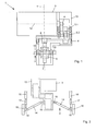
- FIG. 1 an inventive drive 1 is shown schematically in a sectional view. It should be noted that in the FIG. 1 a part of the axis 2 of the inventive drive 1 is not shown.
- the inventive drive 1 comprises an electric machine 3, which acts via an output shaft 4 on a first transmission shaft 5.1, which in turn acts on a second transmission shaft 5.2.
- the second gear shaft 5.2 is engaged with an intermediate shaft 6.
- the intermediate shaft 6 transmits the torque in a direction parallel to the output shaft 4 of the electric machine 3 in the direction of the housing of the electric machine 3.
- the output transmission portion 7 is formed by an outer ring gear which is engaged with a pinion 8 mounted on the intermediate shaft 6.
- a driven by the drive transmission range differential 9 shown schematically, which drives on both sides each differential output shafts 10.
- the differential output shafts 10 are part of the axis 2.
- FIG. 1 is also a median plane 11 of a hospital elevator, which is driven by the drive 1, indicated schematically.
- the drive transmission region 7 is in the center plane 11, ie, centrally with respect to the axis 2 and thus arranged centrally with respect to the entire ambulance.
- a center of gravity 12 of the assembly comprising the electric machine 3 and the gear 13 is arranged close to the center plane 11. This ensures a uniform weight distribution of the mass of the drive 1 in the ambulance.
- the central arrangement of the drive transmission region 7 ensures that on both sides of the differential 9 there is still sufficient space to arrange a mechanically complex independent suspension or the like.
- FIG. 2 is the inventive drive 1 of FIG. 1 in a further sectional view, but in the opposite direction, again shown.
- the FIG. 2 in particular serves to show further elements of axis 2.
- the axle 2 which is driven via the gear 13 by the electric machine, comprises propeller shafts 14, which connect the differential output shafts 10 with wheel shafts 15. On the wheel shafts 15 wheels 16 are mounted respectively.
- the drive of the wheels 16 via the propeller shafts 14 allows independent suspension of the wheels 16, wherein of the independent suspension of the wheels 16 in the FIG. 2 only schematically spring-damper elements 17 are shown, via which the carrying capacity of the wheels 16 on a frame 18 of the crane lift, which is driven by the drive 1, is transmitted. Due to the independent suspension of the wheels 16 with the spring-damper elements 17 a high ride comfort of the ambulance is guaranteed.
Landscapes
- Engineering & Computer Science (AREA)
- Life Sciences & Earth Sciences (AREA)
- Animal Behavior & Ethology (AREA)
- General Health & Medical Sciences (AREA)
- Public Health (AREA)
- Veterinary Medicine (AREA)
- Health & Medical Sciences (AREA)
- Mechanical Engineering (AREA)
- Motor Power Transmission Devices (AREA)
- Arrangement Of Transmissions (AREA)
- Arrangement Or Mounting Of Propulsion Units For Vehicles (AREA)
- Retarders (AREA)
- Shafts, Cranks, Connecting Bars, And Related Bearings (AREA)
Abstract
Description
- Die Erfindung betrifft einen Antrieb für ein Fahrzeug nach dem Oberbegriff des Anspruchs 1.
- Antriebe für Elektro-Krankenfahrstühle weisen eine elektrische Maschine auf, welche die Hinterachse antreibt. Die elektrische Maschine weist eine im Vergleich zur Gesamtmasse des Krankenfahrstuhls vergleichsweise grosse Masse auf und wird daher üblicherweise mittig des Krankenfahrstuhls, insbesondere mittig bezüglich der angetriebenen Achse angeordnet, um die Kippgefahr des Krankenfahrstuhls zu verringern. Auf der Seite der elektrischen Maschine, auf welcher die Abtriebswelle aus dem Gehäuse der elektrischen Maschine heraustritt, ist ein Getriebe angeordnet. Über das Getriebe steht die Abtriebswelle in Wirkverbindung mit der angetriebenen Achse. Die angetriebene Achse verfügt an ihren beiden Seiten jeweils über Räder, die so von der elektrischen Maschine angetrieben werden.
- Problematisch in dem bekannten Stand der Technik ist die häufig mangelhafte Lagerung der Räder, wobei zu berücksichtigen ist, dass Krankenfahrstühle oder andere Personenbeförderungskleinfahrzeuge, beispielsweise vorgeschrieben durch gesetzliche Vorschriften, eine geringe Breite aufweisen. Dies erschwert eine dem Fahrkomfort dienende Einzelradaufhängung der angetriebenen Räder aufgrund Platzmangels.
- Aufgabe der Erfindung ist es, einen Antrieb für ein Fahrzeug, insbesondere für einen Krankenfahrstuhl anzugeben, bei welchem die oben beschriebenen Probleme des Standes der Technik vermindert oder abgestellt sind, insbesondere ist es Aufgabe der Erfindung, einen entsprechenden Antrieb anzugeben, bei dem eine verbesserte Radaufhängung ermöglicht wird.
- Zur Lösung der Aufgabe wird ein Antrieb gemäss Anspruch 1 bereitgestellt. Die erfindungsgemässe Lösung ordnet einen Antriebsübertragungsbereich der angetriebenen Achse im wesentlichen mittig der Achse an. Auf diese Weise wird beidseitig des mittig angeordneten Antriebsübertragungsbereichs Platz für eine bessere Lagerung der Räder geschaffen. Der Antriebsübertragungsbereich der Achse bezeichnet dabei einen Bereich der Achse, in welchem das Antriebsdrehmoment auf die Achse übertragen wird. Dies kann über ein Zahnrad, über einen Riementrieb oder ähnliches geschehen. Vorzugsweise ist auch eine Baugruppe umfassend die elektrische Maschine und ein Getriebe mittig bezüglich der Achse angeordnet, d.h., dass der Schwerpunkt der Baugruppe vorzugsweise auf einer Ebene angeordnet ist, welche senkrecht zu der Achse steht und mittig bezüglich der Achse ist. Dabei bedeutet in Bezug auf die Anordnung des Antriebsübertragungsbereichs oder bezüglich der Anordnung der Baugruppe der Ausdruck "mittig der Achse" vorzugsweise einen Bereich, der die mittleren 40% der Gesamtlänge der Achse oder der Breite des Fahrzeugs umfasst, noch bevorzugter maximal 30% oder 20% oder am bevorzugtsten 10% oder gar 5%. Die mittig angeordnete Maschine bietet den Vorteil einer günstigen Lage des Schwerpunkts des Gesamtfahrzeugs.
- Die Erfindung ist besonders für Personenförderungskleinkraftfahrzeuge, Rollstühle oder Krankenfahrstühle geeignet. Besonders bevorzugt wird die Erfindung bei einem Krankenfahrstuhl eingesetzt, wobei ein bevorzugter Krankenfahrstuhl ein einsitziges Fahrzeug ist oder eine Lehrmasse von max. 300kg aufweist oder eine Bauart bedingte Höchstgeschwindigkeit von 15km/h aufweist oder eine max. Breite von 1,10 m aufweist. Die zulässige Gesamtmasse bevorzugter Krankenfahrstühle beträgt 500 kg. Der Antrieb des Fahrzeugs oder des Krankenfahrstuhls erfolgt bevorzugt ausschliesslich durch die elektrische Maschine, wobei ggf. auch ein manueller Antrieb, beispielsweise bei Ausfall der elektrischen Maschine, möglich sein kann. "Ausschliesslich" bezieht sich dabei vorzugsweise auf Maschinen-Antriebe. Die Erfindung bietet deswegen besondere Vorteile bei Kleinkraftfahrzeugen, Rollstühlen oder Krankenfahrstühlen, da diese Fahrzeuge üblicherweise eine geringe Baugrösse aufweisen, so dass aufwendige mechanische Konstruktionen für eine komfortable Lagerung der angetriebenen Räder erschwert sind.
- Vorzugsweise umfasst der Antrieb ein Getriebe mit fester Untersetzung, über welches die Abtriebswelle mit dem Antriebsübertragungsbereich der Achse in Wirkverbindung steht. Das Getriebe mit fester Untersetzung bietet den Vorteil eines einfachen Aufbaus, wobei zu berücksichtigen ist, dass bei dem Einsatz des Antriebs in den bevorzugten Krankenfahrstühlen ein Getriebe mit fester Untersetzung in Kombination mit der elektrischen Maschine ausreicht, um den gesamten Geschwindigkeitsbereich bis zu Bauart bedingten Höchstgeschwindigkeit des Krankenfahrstuhls abzudecken.
- Vorteilhafterweise umfasst der Antrieb eine Zwischenwelle, die räumlich betrachtet zwischen einem Gehäuse der elektrischen Maschine und der Achse angeordnet ist. Über die Zwischenwelle steht vorzugsweise die Abtriebswelle mit dem Antriebsübertragungsbereich in Wirkverbindung. Dabei bedeutet "zwischen", dass zumindest ein Teilbereich der Zwischenwelle zwischen dem Gehäuse und der Achse angeordnet ist, so dass die Zwischenwelle eine Drehmomentübertragung in umgekehrter Richtung wie die Abtriebswelle der elektrischen Maschine, nur parallel versetzt vornimmt. Dabei ist die Zwischenwelle zweckmässiger Weise parallel zu der Abtriebswelle und zu der Achse angeordnet. "Im wesentlichen parallel" bedeutet dabei parallel im Rahmen üblicher Toleranzen, so dass "im wesentlich parallel" bevorzugt auch ersetzbar ist durch "parallel", wie es der Fachmann versteht.
- Bei bevorzugter Ausführungsform weist die Achse ein Differenzial auf. Ein Differenzial bietet den Vorteil eines höheren Fahrkomforts. Das Differenzial ist vorzugsweise im wesentlichen mittig der Achse angeordnet. Auf diese Weise wird beidseitig ausreichend Platz für eine komfortable Fahrbedingungen bietende Radaufhängung geschaffen. Bei der bevorzugten Ausführungsform ist der Antriebsübertragungsbereich dem Differenzial zugeordnet. Solche bevorzugten Ausführungsformen können ein Differenzial mit einem aussen liegenden Zahnkranz aufweisen, über welchen das Differenzial angetrieben wird, wobei wiederum das Differenzial ggf. über weitere Wellen die Räder der Achse antreibt. Das Differenzial ist also vorzugsweise Teil der Achse.
- Vorteilhafterweise weist die Achse beidseitig einzeln aufgehängte Räder auf. Dies bietet den Vorteil eines erhöhten Fahrkomforts. Die Räder sind vorteilhafterweise jeweils gefedert oder gedämpft aufgehängt. Auf diese Weise wird ein erhöhter Fahrkomfort bei dem angetriebenen Fahrzeug erreicht. Zweckmässigerweise werden die Räder jeweils über Gelenkwellen angetrieben. Dies ermöglicht eine Einzelradaufhängung und den Antrieb der Räder. Die Gelenkwellen verbinden die Räder vorzugsweise mit dem Differenzial. Auf diese Weise wird ein Antrieb der Räder gewährleistet.
- Bevorzugte Ausführungsformen der Erfindung werden anhand der beigelegten Figuren näher beschrieben, wobei die Figuren zeigen
- Figur 1
- eine schematische Schnittansicht eines erfindungsgemässen Antriebs, und
- Figur 2
- eine weitere schematische Schnittansicht des Antriebs der
Figur 1 . - In der
Figur 1 ist ein erfindungsgemässer Antrieb 1 schematisch in einer Schnittansicht gezeigt. Anzumerken ist, dass in derFigur 1 ein Teil der Achse 2 des erfindungsgemässen Antriebs 1 nicht gezeigt ist. Der erfindungsgemässe Antrieb 1 umfasst eine elektrische Maschine 3, welche über eine Abtriebswelle 4 auf eine erste Getriebewelle 5.1 wirkt, die wiederum auf eine zweite Getriebewelle 5.2 wirkt. Die zweite Getriebewelle 5.2 steht in Eingriff mit einer Zwischenwelle 6. Die Zwischenwelle 6 überträgt das Drehmoment in einer Richtung parallel zu der Abtriebswelle 4 der elektrischen Maschine 3 in Richtung des Gehäuses der elektrischen Maschine 3. Am Abtriebs-seitigen Ende der Zwischenwelle 6 wird das Drehmoment auf einen Antriebsübertragungsbereich 7 der Achse 2 übertragen. Der Abtriebsübertragungsbereich 7 wird durch einen äusseren Zahnkranz gebildet, der mit einem auf der Zwischenwelle 6 montierten Ritzel 8 in Eingriff ist. Weiterhin ist in derFigur 1 ein durch den Antriebsübertragungsbereich angetriebenes Differenzial 9 schematisch gezeigt, welches beidseitig jeweils Differenzialabtriebswellen 10 antreibt. Die Differenzialabtriebswellen 10 sind Teil der Achse 2. - In der
Figur 1 ist auch eine Mittelebene 11 eines Krankenfahrstuhls, welcher durch den Antrieb 1 angetrieben wird, schematisch angedeutet. Der Antriebsübertragungsbereich 7 ist in der Mittelebene 11, d.h., mittig bezüglich der Achse 2 und damit mittig bezüglich des gesamten Krankenfahrstuhls angeordnet. Ausserdem ist ein Schwerpunkt 12 der Baugruppe umfassend die elektrische Maschine 3 und das Getriebe 13 nahe bei der Mittelebene 11 angeordnet. Dies gewährleistet eine gleichmässige Gewichtsverteilung der Masse des Antriebs 1 in dem Krankenfahrstuhl. Die mittige Anordnung des Antriebsübertragungsbereichs 7 gewährleistet, dass beidseitig des Differenzials 9 noch ausreichend Platz ist, um eine mechanisch aufwendige Einzelradaufhängung oder ähnliches anzuordnen. - In der
Figur 2 ist der erfindungsgemässe Antrieb 1 derFigur 1 in einer weiteren Schnittansicht, allerdings in entgegengesetzter Blickrichtung, nochmals gezeigt. Für gleiche Teile werden in derFigur 2 gleiche Bezugszeichen wie in derFigur 1 verwendet, wobei in der Darstellung derFigur 2 der Übersichtlichkeit halber einige in derFigur 1 gezeigten Teile oder Bezugszeichen weggelassen wurden. DieFigur 2 dient insbesondere dazu, weitere Elemente der Achse 2 zu zeigen. - Die Achse 2, welche über das Getriebe 13 durch die elektrische Maschine angetrieben wird, umfasst Gelenkwellen 14, welche die Differenzialabtriebswellen 10 mit Radwellen 15 verbinden. Auf den Radwellen 15 sind jeweils Räder 16 montiert. Der Antrieb der Räder 16 über die Gelenkwellen 14 ermöglicht eine Einzelradaufhängung der Räder 16, wobei von der Einzelradaufhängung der Räder 16 in der
Figur 2 lediglich schematisch Feder-Dämpfer-Elemente 17 gezeigt sind, über welche die Tragkraft der Räder 16 auf einen Rahmen 18 des Krankfahrstuhls, welcher durch den Antrieb 1 angetrieben wird, übertragen wird. Durch die Einzelradaufhängung der Räder 16 mit den Feder-Dämpfer-Elementen 17 wird ein hoher Fahrkomfort des Krankenfahrstuhls gewährleistet.Bezugszeichenliste 1 Antrieb 34 67 2 Achse 35 68 3 elektrische Maschine 36 69 4 Abtriebswelle 37 70 5 Getriebewellen 38 71 6 Zwischenwelle 39 72 7 Antriebsübertragungsbereich 40 73 8 Ritzel 41 74 9 Differenzial 42 75 10 Differenzialabtriebswelle 43 76 11 Mittelebene 44 77 12 Schwerpunkt 45 78 13 Getriebe 46 79 14 Gelenkwellen 47 15 Radwellen 48 16 Räder 49 17 Feder-Dämpfer-Elemente 50 18 Rahmen 51 19 52 20 53 21 54 22 55 23 56 24 57 25 58 26 59 27 60 28 61 29 62 30 63 31 64 32 65 33 66
Claims (12)
- Antrieb (1) für ein Fahrzeug, insbesondere für ein Personenbeförderungskleinkraftfahrzeug, einen Rollstuhl oder einen Krankenfahrstuhl, mit
einer elektrischen Maschine (3), die eine Abtriebswelle (4) umfasst, und
einer Achse (2), die mit der Abtriebswelle (4) über einen Antriebsübertragungsbereich (7) der Achse (2) in Wirkverbindung steht,
wobei die Abtriebswelle (4) der elektrischen Maschine (3) im wesentlichen parallel zu der Achse (2) angeordnet ist,
dadurch gekennzeichnet, dass
der Antriebsübertragungsbereich (7) im wesentlichen mittig der Achse (2) angeordnet ist. - Antrieb (1) nach Anspruch 1, dadurch gekennzeichnet, dass die Abtriebswelle (4) mit dem Antriebsübertragungsbereich (7) über ein Getriebe mit fester Untersetzung in Wirkverbindung steht.
- Antrieb (1) nach Anspruch 1 oder 2, dadurch gekennzeichnet, dass die Abtriebswelle (4) mit dem Antriebsübertragungsbereich (7) über eine zumindest teilweise zwischen einem Gehäuse der elektrischen Maschine (3) und der Achse (2) angeordneten Zwischenwelle (6) in Wirkverbindung steht.
- Antrieb (1) nach einem der vorhergehenden Ansprüche, dadurch gekennzeichnet, dass die Achse (2) ein Differenzial (9) aufweist.
- Antrieb (1) nach Anspruch 4, dadurch gekennzeichnet, dass das Differenzial (9) im wesentlichen mittig der Achse (2) angeordnet ist.
- Antrieb (1) nach Anspruch 4 oder 5, dadurch gekennzeichnet, dass der Antriebsübertragungsbereich (7) dem Differenzial (9) zugeordnet ist.
- Antrieb (1) nach einem der vorhergehenden Ansprüche, dadurch gekennzeichnet, dass die Achse (2) beidseitig einzeln aufgehängte Räder (16) aufweist.
- Antrieb (1) nach Anspruch 7, dadurch gekennzeichnet, dass die Räder (16) jeweils gefedert und/oder gedämpft aufgehängt sind.
- Antrieb (1) nach Anspruch 7 oder 8, dadurch gekennzeichnet, dass die Räder (16) jeweils über Gelenkwellen (14) angetrieben werden.
- Antrieb (1) nach Anspruch 7 oder 8, dadurch gekennzeichnet, dass die Räder (16) jeweils über Gelenkwellen (14) mit dem Differenzial (9) verbunden sind.
- Fahrzeug mit einem Antrieb (1) nach einem der Ansprüche 1 bis 10.
- Krankenfahrstuhl mit einem Antrieb (1) nach einem der Ansprüche 1 bis 10.
Applications Claiming Priority (2)
| Application Number | Priority Date | Filing Date | Title |
|---|---|---|---|
| DE102009017838 | 2009-04-20 | ||
| DE102009048995A DE102009048995A1 (de) | 2009-04-20 | 2009-10-09 | Fahrzeugantrieb |
Publications (3)
| Publication Number | Publication Date |
|---|---|
| EP2243451A2 true EP2243451A2 (de) | 2010-10-27 |
| EP2243451A3 EP2243451A3 (de) | 2010-11-03 |
| EP2243451B1 EP2243451B1 (de) | 2013-07-24 |
Family
ID=42751160
Family Applications (1)
| Application Number | Title | Priority Date | Filing Date |
|---|---|---|---|
| EP10004158.1A Not-in-force EP2243451B1 (de) | 2009-04-20 | 2010-04-20 | Fahrzeugantrieb |
Country Status (2)
| Country | Link |
|---|---|
| EP (1) | EP2243451B1 (de) |
| DE (1) | DE102009048995A1 (de) |
Family Cites Families (6)
| Publication number | Priority date | Publication date | Assignee | Title |
|---|---|---|---|---|
| US5251713A (en) * | 1989-09-20 | 1993-10-12 | Honda Giken Kogyo Kabushiki Kaisha | Four wheel vehicle |
| GB2244352B (en) * | 1990-03-27 | 1993-10-13 | Kubota Kk | Electric vehicle |
| CH692718A5 (de) * | 1998-07-21 | 2002-10-15 | Sks Rehab Ag | Rollstuhl. |
| EP1566158B1 (de) * | 2004-02-20 | 2012-04-25 | Honda Motor Co., Ltd. | Kleinelektrofahrzeug |
| JP4657079B2 (ja) * | 2005-10-21 | 2011-03-23 | 本田技研工業株式会社 | 電動小型車両 |
| JP4086251B2 (ja) * | 2005-11-16 | 2008-05-14 | 本田技研工業株式会社 | 小型電動車両の操縦装置 |
-
2009
- 2009-10-09 DE DE102009048995A patent/DE102009048995A1/de not_active Withdrawn
-
2010
- 2010-04-20 EP EP10004158.1A patent/EP2243451B1/de not_active Not-in-force
Non-Patent Citations (1)
| Title |
|---|
| None |
Also Published As
| Publication number | Publication date |
|---|---|
| EP2243451A3 (de) | 2010-11-03 |
| EP2243451B1 (de) | 2013-07-24 |
| DE102009048995A1 (de) | 2010-10-21 |
Similar Documents
| Publication | Publication Date | Title |
|---|---|---|
| EP1889743B1 (de) | Getriebe | |
| EP1470013B1 (de) | Direkt angetriebene antriebsachse mit zwei antriebsmotoren | |
| DE69804773T2 (de) | Antriebseinheit für elektrisch angetriebenes niederflurfahrzeug | |
| EP3027455B1 (de) | Antriebsstrang eines kraftfahrzeugs | |
| EP3165395A1 (de) | Nutzfahrzeug, insbesondere lkw, mit mindestens einem doppelachsaggregat | |
| DE102021205497A1 (de) | Antriebsanordnung | |
| EP3246188A1 (de) | Nutzfahrzeug mit einem parallel-hybrid-antriebsstrang | |
| DE102023202332A1 (de) | Antriebsstrang für ein Kraftfahrzeug | |
| EP3412485A1 (de) | Achsgetriebemodul | |
| DE102017131096A1 (de) | Getriebebaugruppe für einen Getriebemotor einer elektrisch betätigbaren Bremse, Getriebemotor, Feststellbremsanlage und Betriebsbremsanlage | |
| DE69808136T2 (de) | Differentialgetriebe | |
| DE102019205987B4 (de) | Elektrischer Achsantrieb für ein Fahrzeug | |
| DE102017208248A1 (de) | Elektromechanische Kraftfahrzeuglenkung | |
| EP3630574A1 (de) | Drehgestell für schienenfahrzeug | |
| EP1946952A1 (de) | Antriebseinheit für ein Flurförderfahrzeug | |
| DE102018222005A1 (de) | Radnabengetriebe für einen Einzelradantrieb eines Kraftfahrzeugs | |
| DE102022206034A1 (de) | Getriebe für einen Antriebsstrang | |
| EP2243451B1 (de) | Fahrzeugantrieb | |
| DE20201379U1 (de) | Direkt angetriebene Antriebsachse mit zwei Antriebsmotoren | |
| DE20213670U1 (de) | Direkt angetriebene Antriebsachse mit zwei Antriebsmotoren | |
| EP3415356B1 (de) | Achsgetriebemodul | |
| WO2020030434A1 (de) | Fahrzeugachse mit einer elektrischen antriebsvorrichtung und elektrische antriebsvorrichtung | |
| EP1199237B1 (de) | Getriebe für Schienenfahrzeuge | |
| DE102018215188A1 (de) | Elektromechanische Fahrzeuglenkung | |
| EP2295274A1 (de) | Antriebseinheit für ein Kraftfahrzeug |
Legal Events
| Date | Code | Title | Description |
|---|---|---|---|
| PUAI | Public reference made under article 153(3) epc to a published international application that has entered the european phase |
Free format text: ORIGINAL CODE: 0009012 |
|
| PUAL | Search report despatched |
Free format text: ORIGINAL CODE: 0009013 |
|
| AK | Designated contracting states |
Kind code of ref document: A2 Designated state(s): AT BE BG CH CY CZ DE DK EE ES FI FR GB GR HR HU IE IS IT LI LT LU LV MC MK MT NL NO PL PT RO SE SI SK SM TR |
|
| AX | Request for extension of the european patent |
Extension state: AL BA ME RS |
|
| AK | Designated contracting states |
Kind code of ref document: A3 Designated state(s): AT BE BG CH CY CZ DE DK EE ES FI FR GB GR HR HU IE IS IT LI LT LU LV MC MK MT NL NO PL PT RO SE SI SK SM TR |
|
| AX | Request for extension of the european patent |
Extension state: AL BA ME RS |
|
| RIC1 | Information provided on ipc code assigned before grant |
Ipc: A61G 5/04 20060101AFI20100705BHEP Ipc: B62K 5/00 20060101ALI20100924BHEP |
|
| 17P | Request for examination filed |
Effective date: 20110302 |
|
| 17Q | First examination report despatched |
Effective date: 20111101 |
|
| GRAP | Despatch of communication of intention to grant a patent |
Free format text: ORIGINAL CODE: EPIDOSNIGR1 |
|
| GRAS | Grant fee paid |
Free format text: ORIGINAL CODE: EPIDOSNIGR3 |
|
| GRAA | (expected) grant |
Free format text: ORIGINAL CODE: 0009210 |
|
| AK | Designated contracting states |
Kind code of ref document: B1 Designated state(s): AT BE BG CH CY CZ DE DK EE ES FI FR GB GR HR HU IE IS IT LI LT LU LV MC MK MT NL NO PL PT RO SE SI SK SM TR |
|
| REG | Reference to a national code |
Ref country code: GB Ref legal event code: FG4D Free format text: NOT ENGLISH |
|
| REG | Reference to a national code |
Ref country code: CH Ref legal event code: EP |
|
| REG | Reference to a national code |
Ref country code: AT Ref legal event code: REF Ref document number: 622958 Country of ref document: AT Kind code of ref document: T Effective date: 20130815 |
|
| REG | Reference to a national code |
Ref country code: IE Ref legal event code: FG4D Free format text: LANGUAGE OF EP DOCUMENT: GERMAN |
|
| REG | Reference to a national code |
Ref country code: DE Ref legal event code: R096 Ref document number: 502010004091 Country of ref document: DE Effective date: 20130919 |
|
| REG | Reference to a national code |
Ref country code: NL Ref legal event code: T3 |
|
| REG | Reference to a national code |
Ref country code: LT Ref legal event code: MG4D |
|
| PG25 | Lapsed in a contracting state [announced via postgrant information from national office to epo] |
Ref country code: HR Free format text: LAPSE BECAUSE OF FAILURE TO SUBMIT A TRANSLATION OF THE DESCRIPTION OR TO PAY THE FEE WITHIN THE PRESCRIBED TIME-LIMIT Effective date: 20130724 Ref country code: LT Free format text: LAPSE BECAUSE OF FAILURE TO SUBMIT A TRANSLATION OF THE DESCRIPTION OR TO PAY THE FEE WITHIN THE PRESCRIBED TIME-LIMIT Effective date: 20130724 Ref country code: CY Free format text: LAPSE BECAUSE OF FAILURE TO SUBMIT A TRANSLATION OF THE DESCRIPTION OR TO PAY THE FEE WITHIN THE PRESCRIBED TIME-LIMIT Effective date: 20130710 Ref country code: NO Free format text: LAPSE BECAUSE OF FAILURE TO SUBMIT A TRANSLATION OF THE DESCRIPTION OR TO PAY THE FEE WITHIN THE PRESCRIBED TIME-LIMIT Effective date: 20131024 Ref country code: PT Free format text: LAPSE BECAUSE OF FAILURE TO SUBMIT A TRANSLATION OF THE DESCRIPTION OR TO PAY THE FEE WITHIN THE PRESCRIBED TIME-LIMIT Effective date: 20131125 Ref country code: IS Free format text: LAPSE BECAUSE OF FAILURE TO SUBMIT A TRANSLATION OF THE DESCRIPTION OR TO PAY THE FEE WITHIN THE PRESCRIBED TIME-LIMIT Effective date: 20131124 Ref country code: SE Free format text: LAPSE BECAUSE OF FAILURE TO SUBMIT A TRANSLATION OF THE DESCRIPTION OR TO PAY THE FEE WITHIN THE PRESCRIBED TIME-LIMIT Effective date: 20130724 |
|
| PG25 | Lapsed in a contracting state [announced via postgrant information from national office to epo] |
Ref country code: SI Free format text: LAPSE BECAUSE OF FAILURE TO SUBMIT A TRANSLATION OF THE DESCRIPTION OR TO PAY THE FEE WITHIN THE PRESCRIBED TIME-LIMIT Effective date: 20130724 Ref country code: GR Free format text: LAPSE BECAUSE OF FAILURE TO SUBMIT A TRANSLATION OF THE DESCRIPTION OR TO PAY THE FEE WITHIN THE PRESCRIBED TIME-LIMIT Effective date: 20131025 Ref country code: LV Free format text: LAPSE BECAUSE OF FAILURE TO SUBMIT A TRANSLATION OF THE DESCRIPTION OR TO PAY THE FEE WITHIN THE PRESCRIBED TIME-LIMIT Effective date: 20130724 Ref country code: PL Free format text: LAPSE BECAUSE OF FAILURE TO SUBMIT A TRANSLATION OF THE DESCRIPTION OR TO PAY THE FEE WITHIN THE PRESCRIBED TIME-LIMIT Effective date: 20130724 Ref country code: FI Free format text: LAPSE BECAUSE OF FAILURE TO SUBMIT A TRANSLATION OF THE DESCRIPTION OR TO PAY THE FEE WITHIN THE PRESCRIBED TIME-LIMIT Effective date: 20130724 |
|
| PG25 | Lapsed in a contracting state [announced via postgrant information from national office to epo] |
Ref country code: CY Free format text: LAPSE BECAUSE OF FAILURE TO SUBMIT A TRANSLATION OF THE DESCRIPTION OR TO PAY THE FEE WITHIN THE PRESCRIBED TIME-LIMIT Effective date: 20130724 |
|
| PG25 | Lapsed in a contracting state [announced via postgrant information from national office to epo] |
Ref country code: CZ Free format text: LAPSE BECAUSE OF FAILURE TO SUBMIT A TRANSLATION OF THE DESCRIPTION OR TO PAY THE FEE WITHIN THE PRESCRIBED TIME-LIMIT Effective date: 20130724 Ref country code: SK Free format text: LAPSE BECAUSE OF FAILURE TO SUBMIT A TRANSLATION OF THE DESCRIPTION OR TO PAY THE FEE WITHIN THE PRESCRIBED TIME-LIMIT Effective date: 20130724 Ref country code: DK Free format text: LAPSE BECAUSE OF FAILURE TO SUBMIT A TRANSLATION OF THE DESCRIPTION OR TO PAY THE FEE WITHIN THE PRESCRIBED TIME-LIMIT Effective date: 20130724 Ref country code: RO Free format text: LAPSE BECAUSE OF FAILURE TO SUBMIT A TRANSLATION OF THE DESCRIPTION OR TO PAY THE FEE WITHIN THE PRESCRIBED TIME-LIMIT Effective date: 20130724 Ref country code: EE Free format text: LAPSE BECAUSE OF FAILURE TO SUBMIT A TRANSLATION OF THE DESCRIPTION OR TO PAY THE FEE WITHIN THE PRESCRIBED TIME-LIMIT Effective date: 20130724 |
|
| PG25 | Lapsed in a contracting state [announced via postgrant information from national office to epo] |
Ref country code: ES Free format text: LAPSE BECAUSE OF FAILURE TO SUBMIT A TRANSLATION OF THE DESCRIPTION OR TO PAY THE FEE WITHIN THE PRESCRIBED TIME-LIMIT Effective date: 20130724 Ref country code: IT Free format text: LAPSE BECAUSE OF FAILURE TO SUBMIT A TRANSLATION OF THE DESCRIPTION OR TO PAY THE FEE WITHIN THE PRESCRIBED TIME-LIMIT Effective date: 20130724 |
|
| PLBE | No opposition filed within time limit |
Free format text: ORIGINAL CODE: 0009261 |
|
| STAA | Information on the status of an ep patent application or granted ep patent |
Free format text: STATUS: NO OPPOSITION FILED WITHIN TIME LIMIT |
|
| 26N | No opposition filed |
Effective date: 20140425 |
|
| REG | Reference to a national code |
Ref country code: DE Ref legal event code: R097 Ref document number: 502010004091 Country of ref document: DE Effective date: 20140425 |
|
| PGFP | Annual fee paid to national office [announced via postgrant information from national office to epo] |
Ref country code: NL Payment date: 20140430 Year of fee payment: 5 Ref country code: DE Payment date: 20140627 Year of fee payment: 5 |
|
| PG25 | Lapsed in a contracting state [announced via postgrant information from national office to epo] |
Ref country code: LU Free format text: LAPSE BECAUSE OF FAILURE TO SUBMIT A TRANSLATION OF THE DESCRIPTION OR TO PAY THE FEE WITHIN THE PRESCRIBED TIME-LIMIT Effective date: 20140420 Ref country code: MC Free format text: LAPSE BECAUSE OF FAILURE TO SUBMIT A TRANSLATION OF THE DESCRIPTION OR TO PAY THE FEE WITHIN THE PRESCRIBED TIME-LIMIT Effective date: 20130724 |
|
| REG | Reference to a national code |
Ref country code: CH Ref legal event code: PL |
|
| GBPC | Gb: european patent ceased through non-payment of renewal fee |
Effective date: 20140420 |
|
| REG | Reference to a national code |
Ref country code: FR Ref legal event code: ST Effective date: 20141231 |
|
| REG | Reference to a national code |
Ref country code: IE Ref legal event code: MM4A |
|
| PG25 | Lapsed in a contracting state [announced via postgrant information from national office to epo] |
Ref country code: CH Free format text: LAPSE BECAUSE OF NON-PAYMENT OF DUE FEES Effective date: 20140430 Ref country code: GB Free format text: LAPSE BECAUSE OF NON-PAYMENT OF DUE FEES Effective date: 20140420 Ref country code: LI Free format text: LAPSE BECAUSE OF NON-PAYMENT OF DUE FEES Effective date: 20140430 |
|
| PG25 | Lapsed in a contracting state [announced via postgrant information from national office to epo] |
Ref country code: FR Free format text: LAPSE BECAUSE OF NON-PAYMENT OF DUE FEES Effective date: 20140430 |
|
| PG25 | Lapsed in a contracting state [announced via postgrant information from national office to epo] |
Ref country code: IE Free format text: LAPSE BECAUSE OF NON-PAYMENT OF DUE FEES Effective date: 20140420 |
|
| REG | Reference to a national code |
Ref country code: DE Ref legal event code: R082 Ref document number: 502010004091 Country of ref document: DE Representative=s name: PATENTANWAELTE UND RECHTSANWALT DR. WEISS, ARA, DE Ref country code: DE Ref legal event code: R082 Ref document number: 502010004091 Country of ref document: DE Representative=s name: PATENTANWAELTE UND RECHTSANWALT WEISS, ARAT & , DE |
|
| REG | Reference to a national code |
Ref country code: DE Ref legal event code: R119 Ref document number: 502010004091 Country of ref document: DE |
|
| REG | Reference to a national code |
Ref country code: NL Ref legal event code: MM Effective date: 20150501 |
|
| PG25 | Lapsed in a contracting state [announced via postgrant information from national office to epo] |
Ref country code: DE Free format text: LAPSE BECAUSE OF NON-PAYMENT OF DUE FEES Effective date: 20151103 |
|
| PG25 | Lapsed in a contracting state [announced via postgrant information from national office to epo] |
Ref country code: MT Free format text: LAPSE BECAUSE OF FAILURE TO SUBMIT A TRANSLATION OF THE DESCRIPTION OR TO PAY THE FEE WITHIN THE PRESCRIBED TIME-LIMIT Effective date: 20130724 Ref country code: NL Free format text: LAPSE BECAUSE OF NON-PAYMENT OF DUE FEES Effective date: 20150501 |
|
| PG25 | Lapsed in a contracting state [announced via postgrant information from national office to epo] |
Ref country code: SM Free format text: LAPSE BECAUSE OF FAILURE TO SUBMIT A TRANSLATION OF THE DESCRIPTION OR TO PAY THE FEE WITHIN THE PRESCRIBED TIME-LIMIT Effective date: 20130724 |
|
| REG | Reference to a national code |
Ref country code: AT Ref legal event code: MM01 Ref document number: 622958 Country of ref document: AT Kind code of ref document: T Effective date: 20150420 |
|
| PG25 | Lapsed in a contracting state [announced via postgrant information from national office to epo] |
Ref country code: BG Free format text: LAPSE BECAUSE OF FAILURE TO SUBMIT A TRANSLATION OF THE DESCRIPTION OR TO PAY THE FEE WITHIN THE PRESCRIBED TIME-LIMIT Effective date: 20130724 |
|
| PG25 | Lapsed in a contracting state [announced via postgrant information from national office to epo] |
Ref country code: BE Free format text: LAPSE BECAUSE OF FAILURE TO SUBMIT A TRANSLATION OF THE DESCRIPTION OR TO PAY THE FEE WITHIN THE PRESCRIBED TIME-LIMIT Effective date: 20140430 Ref country code: HU Free format text: LAPSE BECAUSE OF FAILURE TO SUBMIT A TRANSLATION OF THE DESCRIPTION OR TO PAY THE FEE WITHIN THE PRESCRIBED TIME-LIMIT; INVALID AB INITIO Effective date: 20100420 Ref country code: TR Free format text: LAPSE BECAUSE OF FAILURE TO SUBMIT A TRANSLATION OF THE DESCRIPTION OR TO PAY THE FEE WITHIN THE PRESCRIBED TIME-LIMIT Effective date: 20130724 |
|
| PG25 | Lapsed in a contracting state [announced via postgrant information from national office to epo] |
Ref country code: AT Free format text: LAPSE BECAUSE OF NON-PAYMENT OF DUE FEES Effective date: 20150420 |
|
| PG25 | Lapsed in a contracting state [announced via postgrant information from national office to epo] |
Ref country code: MK Free format text: LAPSE BECAUSE OF FAILURE TO SUBMIT A TRANSLATION OF THE DESCRIPTION OR TO PAY THE FEE WITHIN THE PRESCRIBED TIME-LIMIT Effective date: 20130724 |