EP2243348B1 - Multifunction side-delivery rake - Google Patents
Multifunction side-delivery rake Download PDFInfo
- Publication number
- EP2243348B1 EP2243348B1 EP20100160663 EP10160663A EP2243348B1 EP 2243348 B1 EP2243348 B1 EP 2243348B1 EP 20100160663 EP20100160663 EP 20100160663 EP 10160663 A EP10160663 A EP 10160663A EP 2243348 B1 EP2243348 B1 EP 2243348B1
- Authority
- EP
- European Patent Office
- Prior art keywords
- raking
- delivery rake
- assembly
- assemblies
- frame
- Prior art date
- Legal status (The legal status is an assumption and is not a legal conclusion. Google has not performed a legal analysis and makes no representation as to the accuracy of the status listed.)
- Active
Links
Images


Classifications
-
- A—HUMAN NECESSITIES
- A01—AGRICULTURE; FORESTRY; ANIMAL HUSBANDRY; HUNTING; TRAPPING; FISHING
- A01D—HARVESTING; MOWING
- A01D78/00—Haymakers with tines moving with respect to the machine
- A01D78/02—Haymakers with tines moving with respect to the machine with tine-carrying bars or equivalent members which interconnect heads rotating about horizontal axes, e.g. of rotary-drum type
- A01D78/04—Haymakers with tines moving with respect to the machine with tine-carrying bars or equivalent members which interconnect heads rotating about horizontal axes, e.g. of rotary-drum type the tine-carrying members moving obliquely or at right angles to the direction of travel of the machine
Definitions
- the present invention regards a multifunction side-delivery rake.
- a side-delivery rake is an agricultural machine that enables sweeping and accumulation into windrows of the mowed fodder.
- Known side-delivery rakes enable in general a limited number of operations to be carried out and for this reason are far from versatile.
- the aim of the present invention is to provide a side-delivery rake that enables the limitations mentioned above to be overcome and that, in particular, is versatile.
- a multifunction side-delivery rake is provided, as defined in Claim 1.
- the multifunction side-delivery rake is of the type having a main frame carried by two wheels, connected to which are two or three raking assemblies provided with combs for forming central or lateral windrows.
- the side-delivery rake comprises a first raking assembly and a second raking assembly, which are arranged at the front of the main frame to form a central windrow, and a third raking assembly, which is set at the rear of the frame and can be translated laterally in a plane parallel to that of the ground and which, when used simultaneously to one or both of the front assemblies, according to its lateral position, enables formation of one lateral windrow, of two lateral windrows of small size, or overturning and displacement of the central windrow formed by the two front raking assemblies.
- the side-delivery rake is made up of a sturdy T-shaped main frame 1 with a rear appendage constrained to the main frame 1 by a sturdy rear frame 2, positioned at the same height as the horizontal part of the main frame, inclined with respect thereto so that its right end is in front of the left end and in turn constrained to the rear part of the main frame 1 in two distinct points.
- a rear raking assembly 3 is traslatable by hydraulic actuation.
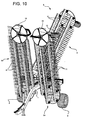
- connection between the rear part of the main frame 1 and the rear raking assembly 3 is provided via a purposely designed double connection 4 ( Figure 11 ), comprising a front part 4A arranged horizontally (which slides on the cross member 2A of the rear frame 2) and a vertical rear part 4B, which are fixed to one another.
- a vertical-screw system 5 Constrained to the vertical rear part of the double connection 4 with a vertical-screw system 5 is the rear raking assembly 3, the height of which with respect to the ground is therefore adjustable through this screw system 5.
- the vertical part 4B of the double connection 4 four or more adjustment screws with horizontal axis are present, which are designed to prevent onset of play caused by possible relative rotation between the vertical part of this double connection 4 and the threaded internal block that enables internal connection between the two parts.
- the top side of these plates of synthetic material is shaped so as to enable positioning of a thin metal sheet, which is hence arranged between the synthetic material and the inner surface of the horizontal part of the double connection 4. Acting on this metal sheet are a number of adjustment screws, the heads of which are positioned on the outside of the outer surface of the horizontal part of the double connection 4; by acting on these, it is possible to recover any possible play that is created following upon wear of the synthetic material.
- the plates of synthetic material are constrained in regard to possible relative horizontal movements via two outer frames screwed to the sides of the horizontal part of the double connection 4.
- a tow coupling 6 is arranged at the front end of the T-shaped main frame 1, can swivel and is adjustable in height by a threaded tie-rod 7 to enable easy hitching of the side-delivery rake to any tractor.
- Two raking assemblies 50, 51 are hinged to the main frame 1 in a front position with respect to the central wheels 8, specularly with respect to the direction of advance (one on the right and one on the left), and comprise each a frame 9 oscillating about the axis of the hinge (right-hand hinge: axis X-X; left-hand hinge: axis Y-Y), mounted on which are two spiders 10, connected to one another by four or more combs 11.
- Two swivel wheels 12 are fixed to the outer end of the oscillating frame 9, one for each raking assembly 50, 51, both of which are adjustable in height with a screw system 15.
- the third raking assembly 3 is hinged at the rear to the sliding double connection 4 and has the same characteristics as the two front ones, except in that it is equipped with two swivel wheels 13, adjustable in height with a screw system 17.
- the raking assembly 3 can be translated hydraulically from the right-hand end to the left-hand end of the cross member 2A of the rear frame 2, and vice versa, with respect to the sliding double connection 4.
- the wheels 8, 12, 13 are moreover adjustable in height in a millimetric way by appropriate cranks (14 on the central frame - 15 on the front assemblies - 16 on the double connection - 17 on the rear assembly).
- each of the three raking assemblies 3, 50, 51 is connected to the main frame 1 by appropriate lightening springs 18 so as to limit the amount of weight that acts on each wheel and optimize operation of the machine, guaranteeing a longer service life thereof and reducing its wear.
- this side-delivery rake with three raking assemblies referred to for simplicity hereinafter as "four-function side-delivery rake" (since it is able to carry out four different types of work), has two raking assemblies 50, 51 in front of the two central wheels 8, one of which extends from the right-hand hinge (axis X-X) towards the right-hand front side, and the other extends from the left hinge (axis Y-Y) towards the left-hand front side.
- the rear raking assembly 3, positioned at the back of the central wheels 8, extends from the rear hinge (axis K-K) towards the left-hand side.
- the hinge of the rear raking assembly 3 can translate according to the horizontal axis Z-Z, enabling displacement of the rear raking assembly 3 from the right-hand end to the left-hand end of the cross member 2A of the rear frame 2, and vice versa.
- the horizontal displacement of the rear raking assembly 3 is controlled by a purposely designed oleodynamic cylinder 19, positioned at the top with respect to the horizontal cross member 2A of the rear frame 2, to which it is constrained in a fixed way on the left-hand side by means of a purposely provided pin 20.
- the other end of the oleodynamic cylinder 19 is connected to the horizontal front part 4A of the sliding double connection 4.
- Said constraint can be provided in different positions so as to enable the oleodynamic cylinder 19, which has a stroke of 60 cm, to displace the rear part of the frame by 120 cm or more: in fact, connected to the top of the horizontal front part 4A of the sliding double connection 4 is a bar 21, which has two or more holes (of which at least one at the right-hand end and one at the left-hand end), the centres of which are at a distance from one another of 60 cm and 30 cm each from the middle of the sliding double connection 4.
- P1 be the position of the hole set at the right-hand end of the bar 21, and P2 the position of the hole at the left-hand end.
- the rear raking assembly 3 With the cylinder 19 completely open and the connection between the cylinder and the bar 21 in the position P2, the rear raking assembly 3 is positioned at the right-hand end.
- the distributor that controls the oleodynamic cylinder 19 is operated on, thus causing closing of the stem, the quick-release pin that joins the stem of the cylinder to the hole P2 of the bar 21 with two holes is released, the oleodynamic cylinder 19 is operated so as to extract the stem thereof, via the quick-release pin 22 the terminal part of the stem is connected to the hole P1 of the horizontal bar 21, and the stem of the oleodynamic cylinder 19 is closed again so as to bring the rear raking assembly 3 to the left-hand end of the rear frame 2.
- the oleodynamic circuit of the side-delivery rake can be connected to that of the tractor by quick-release means, or else be partially or completely separate therefrom, i.e., connected to a tank containing the necessary oil and provided with a circulation pump to be fitted to the power takeoff of the tractor.
- the oleodynamic circuit comprises three oleodynamic motors 23 that drive in rotation the spiders 10 and the six cylinders.
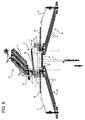
- three cylinders 22 lift the raking assemblies 3, 50, 51, reducing the width of the side-delivery rake so that it can be transported on road, as illustrated in Figure 10 .
- the fourth cylinder 19 enables lateral translation of the rear assembly from one end to the other of the rear frame 2.
- the other two cylinders are positioned within the vertical parts of the T-shaped main frame 1 and have the function of lifting rapidly the entire side-delivery rake to prevent contact of the teeth and of the spiders with the ground both during the operations of manoeuvre when working on the land and during transportation.
- an oleodynamic cylinder 19 is positioned above the horizontal cross member 2A of the rear frame 2 and has the purpose of performing the translation of the rear raking assembly 3; it is actuated by an oleodynamic distributor positioned on the right-hand side of the main frame and connected by purposely provided oleodynamic pipes to the distributors of the tractor.
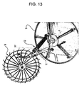
- the front raking assemblies 50, 51 of the four-function side-delivery rake are pre-arranged for application of a further two removable gathering systems 26 in the form of free wheels, which draw their own rotary motion (which enables displacement of the fodder) from friction with the ground.
- These tined wheels are hinged along the axis of pitch (b-b) and, with the aid of a tension spring 27, present a minimal contact with the ground and hence adapt perfectly to its roughness.
- the inclination of all the tines with respect to the vertical plane is obtained by regulating a tie-rod 7 positioned on the front drawbar for connection between the side-delivery rake and the tractor.
- the movement of rotation of the tined reels occurs by means of orbital hydraulic motors 23. This enables reversal of rotation thereof so that the combs, instead of displacing the fodder from outside towards the centre of the side-delivery rake to form a windrow, displace it from the centre outwards spreading it over the ground, opening up the windrow and facilitating drying of the fodder during the daytime hours.
- the four-function side-delivery rake is able to carry out four distinct operations, according to the requirements of harvesting of the fodder, which are described below.
- a first advantage is represented by the high versatility of the side-delivery rake; it can be used for the following operations: a) forming a central windrow, b) forming a lateral windrow, c) forming two lateral windrows of small size, d) turning over and displacing the central windrow, e) strewing-out the windrow according to the requirements of raking of the fodder.
- the four-function side-delivery rake is used in the configuration a) to form the central windrow when the amount of fodder is such as to allow formation of a windrow ready for being swept up by a round baler, or else when it is necessary to put together a number of small windrows or swaths made by a mower/conditioner to form a single large windrow to be swept up by a round baler, or else to put together a number of windrows of small size that have dried during the sunlight hours before twilight so that the fodder absorbs a smaller amount of moisture during night-time hours and will preserve better characteristics.
- the four-function side-delivery rake is used in the configuration b) when it is necessary to perform more than one pass (generally a pass in one direction and a return pass) to obtain a windrow of dimensions sufficient for being gathered by the round baler.
- the four-function side-delivery rake is used in the configuration c) when it is necessary to obtain windrows of small size so that the fodder can dry as much as possible during hours of sunlight. These small-sized windrows will then be brought together using the four-function side-delivery rake in the configuration a) so that windrows of larger size will be formed, which enable a lower exposure to moisture during night-time hours.
- the four-function side-delivery rake is used in the configuration d) when it is necessary to gather the fodder into a central windrow and then turn it over immediately after and displace it laterally so as to lift off the ground also that part of fodder that, lying in the central aisle between the two front raking assemblies, would otherwise present a degree of humidity different from that of the fodder on the surface and would remain in the same place from when it is mowed to when it is swept up by the baler.
- the four-function side-delivery rake is used in the configuration e) when it is necessary open up and spread out the windrow, that is not yet completely dry, to facilitate the drying process.
- a second advantage of the side-delivery rake is represented by the high working capacity, since it guarantees a considerable breath of gathering, which may be, if necessary, increased further with application of two removable free wheels that can be applied at the ends of the front raking assemblies.
- a third advantage of the side-delivery rake is represented by the high rate of advance and by the possibility of adaptation to rough terrain thanks to the presence of swivel wheels positioned very close to the raking assemblies.
- a fourth advantage is represented by the fact that the combs of the raking assemblies penetrate vertically into the fodder and displace it horizontally over the clod and withdraw grazing the ground gently following an epicyclic movement, thus ensuring absolute cleanness of the fodder from soil or stones and, in the case of lucerne, keeping the smaller leaves and the stems rendered brittle by drying intact.
- a fifth advantage is represented by the fact that, since the equipment is drawn along, albeit of large size, it can be used with tractors with small engine displacement enabling reduced fuel consumption, low atmospheric pollution, maximum care for the fodder and for the land.
- a sixth advantage is represented by the fact that, since it is possible to carry out hydraulic closing of the raking assemblies, it is possible to move around easily on the road in full respect for the rules of the highway code as well as to manoeuvre along narrow stretches or where access is difficult.
Landscapes
- Life Sciences & Earth Sciences (AREA)
- Environmental Sciences (AREA)
- Earth Drilling (AREA)
- Harvester Elements (AREA)
- Outside Dividers And Delivering Mechanisms For Harvesters (AREA)
- Harvesting Machines For Specific Crops (AREA)
Description
- The present invention regards a multifunction side-delivery rake.
- As is known, a side-delivery rake is an agricultural machine that enables sweeping and accumulation into windrows of the mowed fodder. Known side-delivery rakes enable in general a limited number of operations to be carried out and for this reason are far from versatile.
- Examples of side-delivery rakes are described in
DE-A-3026912 and inEP-A-0978288 . - The aim of the present invention is to provide a side-delivery rake that enables the limitations mentioned above to be overcome and that, in particular, is versatile.
- According to the present invention a multifunction side-delivery rake is provided, as defined in Claim 1.
- The multifunction side-delivery rake is of the type having a main frame carried by two wheels, connected to which are two or three raking assemblies provided with combs for forming central or lateral windrows. The side-delivery rake comprises a first raking assembly and a second raking assembly, which are arranged at the front of the main frame to form a central windrow, and a third raking assembly, which is set at the rear of the frame and can be translated laterally in a plane parallel to that of the ground and which, when used simultaneously to one or both of the front assemblies, according to its lateral position, enables formation of one lateral windrow, of two lateral windrows of small size, or overturning and displacement of the central windrow formed by the two front raking assemblies.
- The present invention will now be described with reference to the annexed drawings, which illustrate a non-limiting example of embodiment thereof, and in which:
-
Figure 1 is a perspective view three quarters from above of a side-delivery rake according to one embodiment of the present invention, in a first working configuration; -
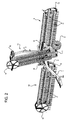
Figure 2 is a perspective view three quarters from above of the side-delivery rake ofFigure 1 , in a second working configuration; -
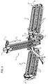
Figure 3 is a perspective view three quarters from above of the side-delivery rake ofFigure 1 , in a third working configuration; -
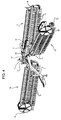
Figure 4 is a perspective view three quarters from above of the side-delivery rake ofFigure 1 , in a fourth working configuration; -
Figure 5 is a side view of the side-delivery rake ofFigure 1 , in a configuration for transportation on the road; -
Figure 6 is a top plan view of the side-delivery rake of -
Figure 1 , in the first working configuration; -
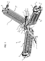
Figure 7 is a top plan view of the side-delivery rake of -
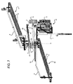
Figure 1 , in the second working configuration; -
Figure 8 is a top plan view of the side-delivery rake of -
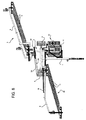
Figure 1 , in the third working configuration; -
Figure 9 is a top plan view of the side-delivery rake of -
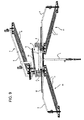
Figure 1 , in the fourth working configuration; -
Figure 10 is a perspective view three quarters from above of the side-delivery rake ofFigure 1 , in a configuration for transportation on the road; -
Figure 11 shows an enlarged detail of the side-delivery rake ofFigure 1 ; -
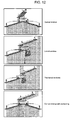
Figure 12 is a schematic illustration of the side-delivery rake ofFigure 1 in use, in the various working configurations; and -
Figure 13 shows a further enlarged detail of the side-delivery rake ofFigure 1 . - With reference to the figures listed above the side-delivery rake according to the present invention is made up of a sturdy T-shaped main frame 1 with a rear appendage constrained to the main frame 1 by a sturdy
rear frame 2, positioned at the same height as the horizontal part of the main frame, inclined with respect thereto so that its right end is in front of the left end and in turn constrained to the rear part of the main frame 1 in two distinct points. Along ahorizontal cross member 2A of therear frame 2, arear raking assembly 3 is traslatable by hydraulic actuation. The connection between the rear part of the main frame 1 and therear raking assembly 3 is provided via a purposely designed double connection 4 (Figure 11 ), comprising afront part 4A arranged horizontally (which slides on thecross member 2A of the rear frame 2) and a verticalrear part 4B, which are fixed to one another. Constrained to the vertical rear part of the double connection 4 with a vertical-screw system 5 is therear raking assembly 3, the height of which with respect to the ground is therefore adjustable through thisscrew system 5. In the bottom area of thevertical part 4B of the double connection 4 four or more adjustment screws with horizontal axis are present, which are designed to prevent onset of play caused by possible relative rotation between the vertical part of this double connection 4 and the threaded internal block that enables internal connection between the two parts. - Positioned within the
horizontal part 4A of the double connection 4 is synthetic material with high mechanical strength, which covers the four internal sides and favours sliding of the double connection 4 on thehorizontal cross member 2A of therear frame 2. The innerside of this synthetic material is appropriately grooved to favour distribution of lubricant product over these surfaces. The top side of these plates of synthetic material is shaped so as to enable positioning of a thin metal sheet, which is hence arranged between the synthetic material and the inner surface of the horizontal part of the double connection 4. Acting on this metal sheet are a number of adjustment screws, the heads of which are positioned on the outside of the outer surface of the horizontal part of the double connection 4; by acting on these, it is possible to recover any possible play that is created following upon wear of the synthetic material. The plates of synthetic material are constrained in regard to possible relative horizontal movements via two outer frames screwed to the sides of the horizontal part of the double connection 4. - A
tow coupling 6 is arranged at the front end of the T-shaped main frame 1, can swivel and is adjustable in height by a threaded tie-rod 7 to enable easy hitching of the side-delivery rake to any tractor. - Mounted to the rear end of the main frame 1 are two
wheels 8 with wide tread, adjustable in height with a screw, which maintain the stability of the side-delivery rake as it moves. Tworaking assemblies central wheels 8, specularly with respect to the direction of advance (one on the right and one on the left), and comprise each aframe 9 oscillating about the axis of the hinge (right-hand hinge: axis X-X; left-hand hinge: axis Y-Y), mounted on which are twospiders 10, connected to one another by four ormore combs 11. Twoswivel wheels 12 are fixed to the outer end of the oscillatingframe 9, one for eachraking assembly - The
third raking assembly 3 is hinged at the rear to the sliding double connection 4 and has the same characteristics as the two front ones, except in that it is equipped with twoswivel wheels 13, adjustable in height with ascrew system 17. Theraking assembly 3 can be translated hydraulically from the right-hand end to the left-hand end of thecross member 2A of therear frame 2, and vice versa, with respect to the sliding double connection 4. - Thanks to the oscillating connection of the three
raking assemblies front assemblies frame 9 of therespective raking assembly rear raking assembly 3, by a purposely designed oval slot, which has dimensions larger than those of the connection pin fixed with respect to the end of the stem of the oleodynamic cylinder and is made in the plate of the oscillatingframe 9 of the rear raking assembly 3), three mutually independent working planes are created, one for each of theraking assemblies wheels raking assemblies wheels raking assemblies appropriate lightening springs 18 so as to limit the amount of weight that acts on each wheel and optimize operation of the machine, guaranteeing a longer service life thereof and reducing its wear. - In practice, this side-delivery rake with three raking assemblies, referred to for simplicity hereinafter as "four-function side-delivery rake" (since it is able to carry out four different types of work), has two
raking assemblies central wheels 8, one of which extends from the right-hand hinge (axis X-X) towards the right-hand front side, and the other extends from the left hinge (axis Y-Y) towards the left-hand front side. Therear raking assembly 3, positioned at the back of thecentral wheels 8, extends from the rear hinge (axis K-K) towards the left-hand side. The hinge of therear raking assembly 3 can translate according to the horizontal axis Z-Z, enabling displacement of therear raking assembly 3 from the right-hand end to the left-hand end of thecross member 2A of therear frame 2, and vice versa. - The horizontal displacement of the
rear raking assembly 3 is controlled by a purposely designedoleodynamic cylinder 19, positioned at the top with respect to thehorizontal cross member 2A of therear frame 2, to which it is constrained in a fixed way on the left-hand side by means of a purposely providedpin 20. The other end of theoleodynamic cylinder 19 is connected to thehorizontal front part 4A of the sliding double connection 4. Said constraint can be provided in different positions so as to enable theoleodynamic cylinder 19, which has a stroke of 60 cm, to displace the rear part of the frame by 120 cm or more: in fact, connected to the top of thehorizontal front part 4A of the sliding double connection 4 is abar 21, which has two or more holes (of which at least one at the right-hand end and one at the left-hand end), the centres of which are at a distance from one another of 60 cm and 30 cm each from the middle of the sliding double connection 4. Let P1 be the position of the hole set at the right-hand end of thebar 21, and P2 the position of the hole at the left-hand end. With thecylinder 19 completely open and the connection between the cylinder and thebar 21 in the position P2, therear raking assembly 3 is positioned at the right-hand end. In order to bring therear raking assembly 3 into the left-hand position, the distributor that controls theoleodynamic cylinder 19 is operated on, thus causing closing of the stem, the quick-release pin that joins the stem of the cylinder to the hole P2 of thebar 21 with two holes is released, theoleodynamic cylinder 19 is operated so as to extract the stem thereof, via the quick-release pin 22 the terminal part of the stem is connected to the hole P1 of thehorizontal bar 21, and the stem of theoleodynamic cylinder 19 is closed again so as to bring therear raking assembly 3 to the left-hand end of therear frame 2. - Operation of the four-function side-delivery rake according to the present invention is very simple.
- It is driven directly from the driving seat of the tractor by a purposely provided remote control that acts on an electronic control unit for actuating a system of solenoid valves which in turn govern the oleodynamic circuit of the side-delivery rake. The oleodynamic circuit of the side-delivery rake can be connected to that of the tractor by quick-release means, or else be partially or completely separate therefrom, i.e., connected to a tank containing the necessary oil and provided with a circulation pump to be fitted to the power takeoff of the tractor.
- The oleodynamic circuit comprises three
oleodynamic motors 23 that drive in rotation thespiders 10 and the six cylinders. In particular, threecylinders 22 lift theraking assemblies Figure 10 . Thefourth cylinder 19 enables lateral translation of the rear assembly from one end to the other of therear frame 2. The other two cylinders are positioned within the vertical parts of the T-shaped main frame 1 and have the function of lifting rapidly the entire side-delivery rake to prevent contact of the teeth and of the spiders with the ground both during the operations of manoeuvre when working on the land and during transportation. Then, anoleodynamic cylinder 19 is positioned above thehorizontal cross member 2A of therear frame 2 and has the purpose of performing the translation of therear raking assembly 3; it is actuated by an oleodynamic distributor positioned on the right-hand side of the main frame and connected by purposely provided oleodynamic pipes to the distributors of the tractor. - The front raking assemblies 50, 51 of the four-function side-delivery rake are pre-arranged for application of a further two
removable gathering systems 26 in the form of free wheels, which draw their own rotary motion (which enables displacement of the fodder) from friction with the ground. These tined wheels are hinged along the axis of pitch (b-b) and, with the aid of atension spring 27, present a minimal contact with the ground and hence adapt perfectly to its roughness. - It is moreover possible to adjust the position of the free wheels about to the axis of yaw with a
screw system 28. These free wheels are positioned in front ofouter disks 25 of the two front raking assemblies as prolongation of the oscillating arm that supports the disks themselves and enable increase up to one metre of the working width of the side-delivery rake. - The inclination of all the tines with respect to the vertical plane is obtained by regulating a tie-
rod 7 positioned on the front drawbar for connection between the side-delivery rake and the tractor. - The movement of rotation of the tined reels occurs by means of orbital
hydraulic motors 23. This enables reversal of rotation thereof so that the combs, instead of displacing the fodder from outside towards the centre of the side-delivery rake to form a windrow, displace it from the centre outwards spreading it over the ground, opening up the windrow and facilitating drying of the fodder during the daytime hours. - The four-function side-delivery rake is able to carry out four distinct operations, according to the requirements of harvesting of the fodder, which are described below.
- 1. FORMATION OF THE CENTRAL WINDROW (
Figures 1 and6 ) With the side-delivery rake in this configuration only the two front raking assemblies are operative. The right-hand raking assembly displaces the fodder from the right-hand side to the centre, and the left-hand raking assembly displaces it from the left-hand side to the centre. As the four-function side-delivery rake advances, a finished central windrow is formed, ready for being gathered. If it is desired to use the four-function side-delivery rake in this configuration, the rear raking assembly can remain in the vertical position set on the right-hand side or left-hand side or else be released from the side-delivery rake. - 2. FORMATION OF A LATERAL WINDROW (
Figures 2 and7 ) With the side-delivery rake in this configuration only the right-hand front raking assembly and the rear raking assembly positioned at the right-hand end of the main frame are operative. The right-hand front raking assembly displaces the fodder from the right-hand side to the centre where it is taken up by the rear raking assembly, which displaces it onto the left-hand side of the side-delivery rake. As the side-delivery rake advances, a lateral windrow is created on the left, which can be displaced or doubled with a second passage of the side-delivery rake in a direction opposite to the first, or else gathered if the amount of fodder were to be sufficient. If it is desired to use the side-delivery rake in this configuration, the left-hand front raking assembly can remain in a vertical position or else be released from the side-delivery rake. - 3. FORMATION OF TWO LATERAL WINDROWS OF SMALL SIZE (
Figures 3 and8 ) With the side-delivery rake in this configuration, only the right-hand front raking assembly and the rear raking assembly positioned at the left-hand end of the main frame are operative. The right-hand front raking assembly displaces the fodder from the right-hand side to the centre forming a lateral windrow of small size; the rear raking assembly displaces the fodder from the right-hand side to the left-hand side of the side-delivery rake to form a second lateral windrow of small size. As the side-delivery rake advances, two lateral windrows at the left of the raking assemblies are created so as to facilitate the process of drying in the meadow during sunlight hours. As night approaches, it is possible to unite these windrows using the four-function side-delivery rake in the configuration for creating the central windrow in such a way as to obtain a windrow of large size so that the fodder is more protected from the damp of the night-time hours. If it is desired to use the side-delivery rake in this configuration, the left-hand front raking assembly can remain in a vertical position or else be released from the side-delivery rake. - DISPLACING IT (
Figures 4 and9 ) With the side-delivery rake in this configuration all three raking assemblies work simultaneously. The two front raking assemblies form the central windrow as per point 1, whereas the third raking assembly, i.e., the rear one, positioned in the proximity of the rear right-hand wheel, turns over and displaces the central windrow created by the two front raking assemblies. This enables a more uniform drying of the entire fodder in so far as even that part of fodder that would otherwise remain immobile on the ground, from when it is mowed to when it is gathered, is lifted off the ground. - With the four-function side-delivery rake of the present invention the advantages outlined in what follows are hence obtained.
- A first advantage is represented by the high versatility of the side-delivery rake; it can be used for the following operations: a) forming a central windrow, b) forming a lateral windrow, c) forming two lateral windrows of small size, d) turning over and displacing the central windrow, e) strewing-out the windrow according to the requirements of raking of the fodder.
- In particular, the four-function side-delivery rake is used in the configuration a) to form the central windrow when the amount of fodder is such as to allow formation of a windrow ready for being swept up by a round baler, or else when it is necessary to put together a number of small windrows or swaths made by a mower/conditioner to form a single large windrow to be swept up by a round baler, or else to put together a number of windrows of small size that have dried during the sunlight hours before twilight so that the fodder absorbs a smaller amount of moisture during night-time hours and will preserve better characteristics.
- The four-function side-delivery rake is used in the configuration b) when it is necessary to perform more than one pass (generally a pass in one direction and a return pass) to obtain a windrow of dimensions sufficient for being gathered by the round baler.
- The four-function side-delivery rake is used in the configuration c) when it is necessary to obtain windrows of small size so that the fodder can dry as much as possible during hours of sunlight. These small-sized windrows will then be brought together using the four-function side-delivery rake in the configuration a) so that windrows of larger size will be formed, which enable a lower exposure to moisture during night-time hours.
- The four-function side-delivery rake is used in the configuration d) when it is necessary to gather the fodder into a central windrow and then turn it over immediately after and displace it laterally so as to lift off the ground also that part of fodder that, lying in the central aisle between the two front raking assemblies, would otherwise present a degree of humidity different from that of the fodder on the surface and would remain in the same place from when it is mowed to when it is swept up by the baler.
- The four-function side-delivery rake is used in the configuration e) when it is necessary open up and spread out the windrow, that is not yet completely dry, to facilitate the drying process.
- A second advantage of the side-delivery rake is represented by the high working capacity, since it guarantees a considerable breath of gathering, which may be, if necessary, increased further with application of two removable free wheels that can be applied at the ends of the front raking assemblies.
- A third advantage of the side-delivery rake is represented by the high rate of advance and by the possibility of adaptation to rough terrain thanks to the presence of swivel wheels positioned very close to the raking assemblies.
- A fourth advantage is represented by the fact that the combs of the raking assemblies penetrate vertically into the fodder and displace it horizontally over the clod and withdraw grazing the ground gently following an epicyclic movement, thus ensuring absolute cleanness of the fodder from soil or stones and, in the case of lucerne, keeping the smaller leaves and the stems rendered brittle by drying intact.
- A fifth advantage is represented by the fact that, since the equipment is drawn along, albeit of large size, it can be used with tractors with small engine displacement enabling reduced fuel consumption, low atmospheric pollution, maximum care for the fodder and for the land.
- A sixth advantage is represented by the fact that, since it is possible to carry out hydraulic closing of the raking assemblies, it is possible to move around easily on the road in full respect for the rules of the highway code as well as to manoeuvre along narrow stretches or where access is difficult.
Claims (12)
- A multifunction side-delivery rake, characterized in that it is able to carry out four distinct operations of raking, namely: formation of a central windrow, formation of a central windrow with subsequent overturning and lateral displacement thereof, formation of a single lateral windrow of large size, and formation of two distinct lateral windrows of small size, in addition to the operation of tedding of the windrow.
- The side-delivery rake according to Claim 1, characterized in that it has a main frame (1) carried by wheels (8), connected to which are a first raking assembly (50), a second raking assembly (51), and a third raking assembly (3), provided with respective combs (11) for formation of central or lateral windrows; the first and second raking assemblies (50, 51) being arranged at the front of the main frame (1) to form of a central windrow; the third raking assembly (3) being set at the rear of the main frame (1) and translatable laterally in a plane parallel to that of the ground and being designed to be used simultaneously with one of the first and second raking assemblies (50, 51) or with both of them to enable, according to its position, formation of a lateral windrow, of two lateral windrows of small size, or overturning and displacement of the central windrow formed by the first and second raking assemblies (50, 51).
- The side-delivery rake according to Claim 2, characterized in that the main frame (1) is T-shaped and in that it comprises a rear appendage constrained to the main frame (1) via a rear frame (2), which is positioned at the same height as a horizontal part of the main frame (1), comprises a horizontal cross member (2A), set oblique with respect to the main frame (1), so that a first end of the cross member (2A) is in front of a second end opposite thereto, and is in turn constrained to a rear part of the main frame (1) in two distinct points; the third raking assembly (3) being translatable along the horizontal cross member (2A) of the rear frame (2).
- The side-delivery rake according to Claim 3, characterized in that it comprises an oleodynamic cylinder (19) for translating the third raking assembly (3) along the cross member (2A) of the rear frame (2) and in that the rear part of the main frame (1) is connected to the third raking assembly (3) via a double connection (4) comprising a first portion (4A), set horizontal and sliding on the cross member (2A) of the rear frame (2), and a second, vertical, portion (4B) fixed to the first portion (4A).
- The side-delivery rake according to Claim 4, characterized in that the third raking assembly (3) is constrained to the second, vertical, portion (4B) of the double connection (4) with a vertical-screw system so that a height from the ground of the third raking assembly (3) is adjustable by the screw system.
- The side-delivery rake according to Claim 4 or 5, characterized in that the first and second raking assemblies (50, 51) are hinged to the frame, in a front position with respect to the wheels (8), in a way specular with respect to the direction of advance, respectively on the right and on the left; the first and second raking assemblies (50, 51) each comprising a frame (9) oscillating about a respective hinge axis (X-X, Y-Y), two spiders (10), mounted on the respective oscillating frame (9) and connected to one another by at least four combs (11), and swivel wheels (12), fixed to outer ends of the respective oscillating frames (9) and adjustable in height with screw means; and in that the third raking assembly (3) is hinged at the rear of the sliding double connection (4).
- The side-delivery rake according to Claim 6, characterized in that, thanks to the oscillating connection (9) of the first, second, and third raking assemblies (50, 51, 3), three independent working planes are created, one for each of the raking assemblies (50, 51, 3) so as to enable adaptation to the irregularities of the terrain and working on terrains with variable and non-uniform inclination, the wheels being positioned so as to be close to the raking assemblies (50, 51, 3) and being moreover adjustable in height in a millimetric way by purposely provided cranks; and in that, for the first and second raking assemblies (50, 51), the oscillating connection is obtained by slots having an oval shape and internal dimensions greater than those of pins for connection with the oscillating frame (9) of the respective one between the first raking assembly (50) and the second raking assembly (51), the slots being set at ends of stems of further oleodynamic cylinders (18) of the first and second raking assemblies (50, 51); and, for the third raking assembly (3), the oscillating connection is obtained by a further oval slot made in a plate of the oscillating frame (9) of the third raking assembly (3) and having dimensions greater than those of the connection pin fixed with respect to the end of the stem of the oleodynamic cylinder (19).
- The side-delivery rake according to Claim 6 or 7, characterized in that each of the first, second, and third raking assemblies is connected to the main frame by lightening springs so as to limit the amount of weight that acts on each of the outer wheels.
- The side-delivery rake according to any one of Claims 6 to 8, characterized in that the oleodynamic cylinder (19) is positioned above the horizontal cross member (2A) of the rear frame (2) and has an end constrained in a fixed way to the horizontal cross member (2A) of the rear frame (2) by a pin; an opposite end of the oleodynamic cylinder (19) being connected to the horizontal part (4A) of the sliding double connection (4) so as to enable the oleodynamic cylinder (19) to displace the rear part of the frame by a distance greater than that of its own stroke by a bar (21) connected at the top to the horizontal part (4A) of the sliding double connection (4) and having at least two opposite end holes to which the end of the stem of the oleodynamic cylinder (19) can be connected.
- The side-delivery rake according to any one of Claims 6 to 9, characterized in that the first and second raking assemblies (50, 51) are pre-arranged for application of a further two removable gathering systems having the shape of tined free wheels that draw their rotary motion which enables displacement of the fodder from friction with the ground; the tined wheels being hinged along an axis of pitch and being positioned in front of outer disks of the first and second raking assemblies as prolongation of the oscillating frame by which the disks are carried; a position of the free wheels being adjustable about an axis of yaw with a screw system.
- The side-delivery rake according to any one of Claims 6 to 10, characterized in that it comprises orbital hydraulic motors coupled to the spiders (10) in such a way that the rotation of the spiders (10) is reversible.
- The side-delivery rake according to any one of Claims 6 to 11, characterized in that, when the side-delivery rake is configured for formation of a central windrow, the first and second raking assemblies (50, 51) are operative and horizontal, whereas the third raking assembly (3) is kept raised in a substantially vertical position, on the right-hand end or on the left-hand end of the rear frame (2); when the side-delivery rake is configured for formation of a single lateral windrow, the first raking assembly (50) and the third raking assembly (3) are operative and horizontal, with the third raking assembly (3) positioned on the right-hand side of the rear frame (2), whereas the second raking assembly (51) is kept raised in a substantially vertical position; when the side-delivery rake is configured for formation of two lateral windrows of small size, the first raking assembly (50) and the third raking assembly (3) are operative and horizontal, with the third raking assembly (3) positioned on the left-hand side of the rear frame (2), whereas the second raking assembly (51) is kept raised in a substantially vertical position; when the side-delivery rake is configured for formation of a central windrow with subsequent overturning and displacement thereof, the first, second, and third raking assemblies (50, 51, 3) are operative and horizontal, with the third raking assembly (3) positioned at the right-hand end of the rear frame (2); when only two of the three raking assemblies (50, 51, 3) are operative and horizontal, the remaining raking assembly being disconnected from the side-delivery rake.
Applications Claiming Priority (1)
| Application Number | Priority Date | Filing Date | Title |
|---|---|---|---|
| ITPV2009A000006A IT1393742B1 (en) | 2009-04-23 | 2009-04-23 | MULTI-PIPE AND MULTIFUNCTION SPAND-WHEEL DRILL RACK |
Publications (2)
| Publication Number | Publication Date |
|---|---|
| EP2243348A1 EP2243348A1 (en) | 2010-10-27 |
| EP2243348B1 true EP2243348B1 (en) | 2012-12-26 |
Family
ID=41665000
Family Applications (1)
| Application Number | Title | Priority Date | Filing Date |
|---|---|---|---|
| EP20100160663 Active EP2243348B1 (en) | 2009-04-23 | 2010-04-22 | Multifunction side-delivery rake |
Country Status (3)
| Country | Link |
|---|---|
| EP (1) | EP2243348B1 (en) |
| ES (1) | ES2401726T3 (en) |
| IT (1) | IT1393742B1 (en) |
Family Cites Families (3)
| Publication number | Priority date | Publication date | Assignee | Title |
|---|---|---|---|---|
| DE3026912A1 (en) * | 1980-07-16 | 1982-02-04 | Karl Mengele & Söhne Maschinenfabrik und Eisengießerei GmbH & Co, 8870 Günzburg | COMPUTING DEVICE |
| CN1259053A (en) | 1997-04-11 | 2000-07-05 | 藤泽药品工业株式会社 | Medicinal composition |
| NL1009789C2 (en) * | 1998-08-03 | 2000-02-04 | Maasland Nv | Device for moving crop lying on the ground. |
-
2009
- 2009-04-23 IT ITPV2009A000006A patent/IT1393742B1/en active
-
2010
- 2010-04-22 EP EP20100160663 patent/EP2243348B1/en active Active
- 2010-04-22 ES ES10160663T patent/ES2401726T3/en active Active
Also Published As
| Publication number | Publication date |
|---|---|
| ES2401726T3 (en) | 2013-04-24 |
| IT1393742B1 (en) | 2012-05-08 |
| ITPV20090006A1 (en) | 2010-10-24 |
| EP2243348A1 (en) | 2010-10-27 |
Similar Documents
| Publication | Publication Date | Title |
|---|---|---|
| DE19716379C1 (en) | Agricultural harvester machine for standing crops | |
| RU2657875C2 (en) | Improved crop harvesting machine | |
| EP3135099B1 (en) | Agricultural machine with a pickup device | |
| RU2569294C2 (en) | Hay-harvesting device | |
| US3834142A (en) | Side delivery rake | |
| US10264730B2 (en) | Agricultural tool control system | |
| DE202011101277U1 (en) | mower | |
| US4685282A (en) | Hay rake assembly | |
| DE10011730C2 (en) | mower | |
| EP2687074A1 (en) | Support carriage for an agricultural machine | |
| DE2753102A1 (en) | SWATHMOWER WITH ASSIGNED STALL PROCESSING DEVICE | |
| EP1095555B1 (en) | Haymaking machine | |
| EP3982710A1 (en) | Hopper hay rake for the harvesting of straw, in particular from legumes | |
| DE19921957A1 (en) | Control for agricultural work machine | |
| EP2243348B1 (en) | Multifunction side-delivery rake | |
| DE102008042392B4 (en) | Harvesting header for agricultural harvesting machines | |
| DE102009017400A1 (en) | Agricultural harvesting machine, e.g. for hay or straw or grass, has a lateral conveyor to transfer harvest from spiked pick-up roller to the conveyor/treatment unit with position controlled to spiked roller height setting | |
| US6354382B1 (en) | Positionable work implement | |
| EP3092890A1 (en) | Cutting assembly for a harvester | |
| EP0937383B1 (en) | Haymaking machine | |
| EP2030499B1 (en) | Towed swather | |
| EP1829444B1 (en) | Rotary swather | |
| DE19645629A1 (en) | Rotary swathe machine for crops | |
| DE102011113121A1 (en) | Star wheel rake for agricultural vehicle e.g. tractor, has gantry portion that is provided with carrier portions, and star wheels which are hinged over hinge elements so as to swing from operating position to transport position | |
| EP2055174B1 (en) | Self-propelled agricultural harvester |
Legal Events
| Date | Code | Title | Description |
|---|---|---|---|
| PUAI | Public reference made under article 153(3) epc to a published international application that has entered the european phase |
Free format text: ORIGINAL CODE: 0009012 |
|
| AK | Designated contracting states |
Kind code of ref document: A1 Designated state(s): AT BE BG CH CY CZ DE DK EE ES FI FR GB GR HR HU IE IS IT LI LT LU LV MC MK MT NL NO PL PT RO SE SI SK SM TR |
|
| AX | Request for extension of the european patent |
Extension state: AL BA ME RS |
|
| 17P | Request for examination filed |
Effective date: 20110427 |
|
| GRAP | Despatch of communication of intention to grant a patent |
Free format text: ORIGINAL CODE: EPIDOSNIGR1 |
|
| RIC1 | Information provided on ipc code assigned before grant |
Ipc: A01D 78/04 20060101ALI20120522BHEP Ipc: A01D 78/00 20060101AFI20120522BHEP |
|
| GRAS | Grant fee paid |
Free format text: ORIGINAL CODE: EPIDOSNIGR3 |
|
| GRAP | Despatch of communication of intention to grant a patent |
Free format text: ORIGINAL CODE: EPIDOSNIGR1 |
|
| GRAA | (expected) grant |
Free format text: ORIGINAL CODE: 0009210 |
|
| AK | Designated contracting states |
Kind code of ref document: B1 Designated state(s): AT BE BG CH CY CZ DE DK EE ES FI FR GB GR HR HU IE IS IT LI LT LU LV MC MK MT NL NO PL PT RO SE SI SK SM TR |
|
| REG | Reference to a national code |
Ref country code: GB Ref legal event code: FG4D |
|
| RIN1 | Information on inventor provided before grant (corrected) |
Inventor name: REPOSSI, FRANCESCO Inventor name: REPOSSI, GABRIELE |
|
| REG | Reference to a national code |
Ref country code: CH Ref legal event code: EP |
|
| REG | Reference to a national code |
Ref country code: AT Ref legal event code: REF Ref document number: 589965 Country of ref document: AT Kind code of ref document: T Effective date: 20130115 |
|
| REG | Reference to a national code |
Ref country code: DE Ref legal event code: R096 Ref document number: 602010004264 Country of ref document: DE Effective date: 20130228 |
|
| REG | Reference to a national code |
Ref country code: ES Ref legal event code: FG2A Ref document number: 2401726 Country of ref document: ES Kind code of ref document: T3 Effective date: 20130424 |
|
| PG25 | Lapsed in a contracting state [announced via postgrant information from national office to epo] |
Ref country code: NO Free format text: LAPSE BECAUSE OF FAILURE TO SUBMIT A TRANSLATION OF THE DESCRIPTION OR TO PAY THE FEE WITHIN THE PRESCRIBED TIME-LIMIT Effective date: 20130326 Ref country code: HR Free format text: LAPSE BECAUSE OF FAILURE TO SUBMIT A TRANSLATION OF THE DESCRIPTION OR TO PAY THE FEE WITHIN THE PRESCRIBED TIME-LIMIT Effective date: 20121226 Ref country code: LT Free format text: LAPSE BECAUSE OF FAILURE TO SUBMIT A TRANSLATION OF THE DESCRIPTION OR TO PAY THE FEE WITHIN THE PRESCRIBED TIME-LIMIT Effective date: 20121226 Ref country code: SE Free format text: LAPSE BECAUSE OF FAILURE TO SUBMIT A TRANSLATION OF THE DESCRIPTION OR TO PAY THE FEE WITHIN THE PRESCRIBED TIME-LIMIT Effective date: 20121226 |
|
| REG | Reference to a national code |
Ref country code: AT Ref legal event code: MK05 Ref document number: 589965 Country of ref document: AT Kind code of ref document: T Effective date: 20121226 |
|
| REG | Reference to a national code |
Ref country code: LT Ref legal event code: MG4D |
|
| REG | Reference to a national code |
Ref country code: NL Ref legal event code: VDEP Effective date: 20121226 |
|
| PG25 | Lapsed in a contracting state [announced via postgrant information from national office to epo] |
Ref country code: LV Free format text: LAPSE BECAUSE OF FAILURE TO SUBMIT A TRANSLATION OF THE DESCRIPTION OR TO PAY THE FEE WITHIN THE PRESCRIBED TIME-LIMIT Effective date: 20121226 Ref country code: SI Free format text: LAPSE BECAUSE OF FAILURE TO SUBMIT A TRANSLATION OF THE DESCRIPTION OR TO PAY THE FEE WITHIN THE PRESCRIBED TIME-LIMIT Effective date: 20121226 Ref country code: GR Free format text: LAPSE BECAUSE OF FAILURE TO SUBMIT A TRANSLATION OF THE DESCRIPTION OR TO PAY THE FEE WITHIN THE PRESCRIBED TIME-LIMIT Effective date: 20130327 |
|
| PG25 | Lapsed in a contracting state [announced via postgrant information from national office to epo] |
Ref country code: BG Free format text: LAPSE BECAUSE OF FAILURE TO SUBMIT A TRANSLATION OF THE DESCRIPTION OR TO PAY THE FEE WITHIN THE PRESCRIBED TIME-LIMIT Effective date: 20130326 Ref country code: CZ Free format text: LAPSE BECAUSE OF FAILURE TO SUBMIT A TRANSLATION OF THE DESCRIPTION OR TO PAY THE FEE WITHIN THE PRESCRIBED TIME-LIMIT Effective date: 20121226 Ref country code: EE Free format text: LAPSE BECAUSE OF FAILURE TO SUBMIT A TRANSLATION OF THE DESCRIPTION OR TO PAY THE FEE WITHIN THE PRESCRIBED TIME-LIMIT Effective date: 20121226 Ref country code: SK Free format text: LAPSE BECAUSE OF FAILURE TO SUBMIT A TRANSLATION OF THE DESCRIPTION OR TO PAY THE FEE WITHIN THE PRESCRIBED TIME-LIMIT Effective date: 20121226 Ref country code: IS Free format text: LAPSE BECAUSE OF FAILURE TO SUBMIT A TRANSLATION OF THE DESCRIPTION OR TO PAY THE FEE WITHIN THE PRESCRIBED TIME-LIMIT Effective date: 20130426 Ref country code: BE Free format text: LAPSE BECAUSE OF FAILURE TO SUBMIT A TRANSLATION OF THE DESCRIPTION OR TO PAY THE FEE WITHIN THE PRESCRIBED TIME-LIMIT Effective date: 20121226 Ref country code: AT Free format text: LAPSE BECAUSE OF FAILURE TO SUBMIT A TRANSLATION OF THE DESCRIPTION OR TO PAY THE FEE WITHIN THE PRESCRIBED TIME-LIMIT Effective date: 20121226 |
|
| PG25 | Lapsed in a contracting state [announced via postgrant information from national office to epo] |
Ref country code: NL Free format text: LAPSE BECAUSE OF FAILURE TO SUBMIT A TRANSLATION OF THE DESCRIPTION OR TO PAY THE FEE WITHIN THE PRESCRIBED TIME-LIMIT Effective date: 20121226 Ref country code: PL Free format text: LAPSE BECAUSE OF FAILURE TO SUBMIT A TRANSLATION OF THE DESCRIPTION OR TO PAY THE FEE WITHIN THE PRESCRIBED TIME-LIMIT Effective date: 20121226 Ref country code: RO Free format text: LAPSE BECAUSE OF FAILURE TO SUBMIT A TRANSLATION OF THE DESCRIPTION OR TO PAY THE FEE WITHIN THE PRESCRIBED TIME-LIMIT Effective date: 20121226 Ref country code: PT Free format text: LAPSE BECAUSE OF FAILURE TO SUBMIT A TRANSLATION OF THE DESCRIPTION OR TO PAY THE FEE WITHIN THE PRESCRIBED TIME-LIMIT Effective date: 20130426 |
|
| PG25 | Lapsed in a contracting state [announced via postgrant information from national office to epo] |
Ref country code: DK Free format text: LAPSE BECAUSE OF FAILURE TO SUBMIT A TRANSLATION OF THE DESCRIPTION OR TO PAY THE FEE WITHIN THE PRESCRIBED TIME-LIMIT Effective date: 20121226 |
|
| PLBE | No opposition filed within time limit |
Free format text: ORIGINAL CODE: 0009261 |
|
| STAA | Information on the status of an ep patent application or granted ep patent |
Free format text: STATUS: NO OPPOSITION FILED WITHIN TIME LIMIT |
|
| PG25 | Lapsed in a contracting state [announced via postgrant information from national office to epo] |
Ref country code: MC Free format text: LAPSE BECAUSE OF FAILURE TO SUBMIT A TRANSLATION OF THE DESCRIPTION OR TO PAY THE FEE WITHIN THE PRESCRIBED TIME-LIMIT Effective date: 20121226 Ref country code: CY Free format text: LAPSE BECAUSE OF FAILURE TO SUBMIT A TRANSLATION OF THE DESCRIPTION OR TO PAY THE FEE WITHIN THE PRESCRIBED TIME-LIMIT Effective date: 20121226 |
|
| 26N | No opposition filed |
Effective date: 20130927 |
|
| PG25 | Lapsed in a contracting state [announced via postgrant information from national office to epo] |
Ref country code: IT Free format text: LAPSE BECAUSE OF FAILURE TO SUBMIT A TRANSLATION OF THE DESCRIPTION OR TO PAY THE FEE WITHIN THE PRESCRIBED TIME-LIMIT Effective date: 20121226 |
|
| REG | Reference to a national code |
Ref country code: DE Ref legal event code: R097 Ref document number: 602010004264 Country of ref document: DE Effective date: 20130927 |
|
| REG | Reference to a national code |
Ref country code: IE Ref legal event code: MM4A |
|
| PG25 | Lapsed in a contracting state [announced via postgrant information from national office to epo] |
Ref country code: IE Free format text: LAPSE BECAUSE OF NON-PAYMENT OF DUE FEES Effective date: 20130422 |
|
| REG | Reference to a national code |
Ref country code: CH Ref legal event code: PL |
|
| GBPC | Gb: european patent ceased through non-payment of renewal fee |
Effective date: 20140422 |
|
| PG25 | Lapsed in a contracting state [announced via postgrant information from national office to epo] |
Ref country code: GB Free format text: LAPSE BECAUSE OF NON-PAYMENT OF DUE FEES Effective date: 20140422 Ref country code: CH Free format text: LAPSE BECAUSE OF NON-PAYMENT OF DUE FEES Effective date: 20140430 Ref country code: LI Free format text: LAPSE BECAUSE OF NON-PAYMENT OF DUE FEES Effective date: 20140430 |
|
| PG25 | Lapsed in a contracting state [announced via postgrant information from national office to epo] |
Ref country code: MT Free format text: LAPSE BECAUSE OF FAILURE TO SUBMIT A TRANSLATION OF THE DESCRIPTION OR TO PAY THE FEE WITHIN THE PRESCRIBED TIME-LIMIT Effective date: 20121226 |
|
| PG25 | Lapsed in a contracting state [announced via postgrant information from national office to epo] |
Ref country code: SM Free format text: LAPSE BECAUSE OF FAILURE TO SUBMIT A TRANSLATION OF THE DESCRIPTION OR TO PAY THE FEE WITHIN THE PRESCRIBED TIME-LIMIT Effective date: 20121226 |
|
| PG25 | Lapsed in a contracting state [announced via postgrant information from national office to epo] |
Ref country code: TR Free format text: LAPSE BECAUSE OF FAILURE TO SUBMIT A TRANSLATION OF THE DESCRIPTION OR TO PAY THE FEE WITHIN THE PRESCRIBED TIME-LIMIT Effective date: 20121226 |
|
| PG25 | Lapsed in a contracting state [announced via postgrant information from national office to epo] |
Ref country code: LU Free format text: LAPSE BECAUSE OF NON-PAYMENT OF DUE FEES Effective date: 20130422 Ref country code: HU Free format text: LAPSE BECAUSE OF FAILURE TO SUBMIT A TRANSLATION OF THE DESCRIPTION OR TO PAY THE FEE WITHIN THE PRESCRIBED TIME-LIMIT; INVALID AB INITIO Effective date: 20100422 Ref country code: MK Free format text: LAPSE BECAUSE OF FAILURE TO SUBMIT A TRANSLATION OF THE DESCRIPTION OR TO PAY THE FEE WITHIN THE PRESCRIBED TIME-LIMIT Effective date: 20121226 |
|
| REG | Reference to a national code |
Ref country code: FR Ref legal event code: PLFP Year of fee payment: 7 |
|
| REG | Reference to a national code |
Ref country code: FR Ref legal event code: PLFP Year of fee payment: 8 |
|
| REG | Reference to a national code |
Ref country code: FR Ref legal event code: PLFP Year of fee payment: 9 |
|
| PGFP | Annual fee paid to national office [announced via postgrant information from national office to epo] |
Ref country code: DE Payment date: 20200430 Year of fee payment: 11 |
|
| REG | Reference to a national code |
Ref country code: DE Ref legal event code: R119 Ref document number: 602010004264 Country of ref document: DE |
|
| PG25 | Lapsed in a contracting state [announced via postgrant information from national office to epo] |
Ref country code: DE Free format text: LAPSE BECAUSE OF NON-PAYMENT OF DUE FEES Effective date: 20211103 |
|
| P01 | Opt-out of the competence of the unified patent court (upc) registered |
Effective date: 20230516 |
|
| PGFP | Annual fee paid to national office [announced via postgrant information from national office to epo] |
Ref country code: FR Payment date: 20230421 Year of fee payment: 14 Ref country code: ES Payment date: 20230510 Year of fee payment: 14 |
|
| PGFP | Annual fee paid to national office [announced via postgrant information from national office to epo] |
Ref country code: FI Payment date: 20230424 Year of fee payment: 14 |