EP2243214B1 - Method and system for braking an ac motor - Google Patents
Method and system for braking an ac motor Download PDFInfo
- Publication number
- EP2243214B1 EP2243214B1 EP09712911.8A EP09712911A EP2243214B1 EP 2243214 B1 EP2243214 B1 EP 2243214B1 EP 09712911 A EP09712911 A EP 09712911A EP 2243214 B1 EP2243214 B1 EP 2243214B1
- Authority
- EP
- European Patent Office
- Prior art keywords
- motor
- variable frequency
- frequency drive
- contactor
- current
- Prior art date
- Legal status (The legal status is an assumption and is not a legal conclusion. Google has not performed a legal analysis and makes no representation as to the accuracy of the status listed.)
- Not-in-force
Links
Images


Classifications
-
- H—ELECTRICITY
- H02—GENERATION; CONVERSION OR DISTRIBUTION OF ELECTRIC POWER
- H02P—CONTROL OR REGULATION OF ELECTRIC MOTORS, ELECTRIC GENERATORS OR DYNAMO-ELECTRIC CONVERTERS; CONTROLLING TRANSFORMERS, REACTORS OR CHOKE COILS
- H02P3/00—Arrangements for stopping or slowing electric motors, generators, or dynamo-electric converters
- H02P3/06—Arrangements for stopping or slowing electric motors, generators, or dynamo-electric converters for stopping or slowing an individual dynamo-electric motor or dynamo-electric converter
- H02P3/18—Arrangements for stopping or slowing electric motors, generators, or dynamo-electric converters for stopping or slowing an individual dynamo-electric motor or dynamo-electric converter for stopping or slowing an ac motor
- H02P3/22—Arrangements for stopping or slowing electric motors, generators, or dynamo-electric converters for stopping or slowing an individual dynamo-electric motor or dynamo-electric converter for stopping or slowing an ac motor by short-circuit or resistive braking
-
- H—ELECTRICITY
- H02—GENERATION; CONVERSION OR DISTRIBUTION OF ELECTRIC POWER
- H02P—CONTROL OR REGULATION OF ELECTRIC MOTORS, ELECTRIC GENERATORS OR DYNAMO-ELECTRIC CONVERTERS; CONTROLLING TRANSFORMERS, REACTORS OR CHOKE COILS
- H02P21/00—Arrangements or methods for the control of electric machines by vector control, e.g. by control of field orientation
- H02P21/36—Arrangements for braking or slowing; Four quadrant control
Definitions
- This application discloses an invention that is related, generally and in various embodiments, to a method and system for braking an AC motor. More specifically, this application is related to braking an AC motor with a variable frequency drive.
- variable frequency drives are typically devices used to control the rotational speed of an alternating current (AC) motor by controlling the frequency of electrical power delivered to the motor.
- AC alternating current
- variable frequency drives, and accompanying control circuits are described in detail in U.S. Patent No. 7,327,111 to Rastogi et al. , the disclosure of which is hereby fully incorporated by reference.
- FIG. 1 illustrates an exemplary variable frequency drive 100 for providing electrical power to motor 130.
- Variable frequency drive 100 includes a control circuit 110 and a power circuit 115.
- Control circuit 110 receives incoming input commands 105. Input commands 105 may be a request to increase or decrease the speed of the motor 130, which requires variable frequency drive 100 to adjust the electrical power output by power circuit 115 and delivered to motor 130.
- Control circuit 110 monitors current feedback 120 and voltage feedback 125 from the outputted electrical power to determine if any changes should be made to the output to either adjust or maintain conditions at motor 130.
- the variable frequency drive may also include a field supply.
- the control circuit controls the operation of the power circuit and, for synchronous motor applications, also enables/disables the associated field supply.
- the power circuit may include a rectifier and an inverter, and provides power to the windings of motor 130 connected to the variable frequency drive 100.
- the field supply provides power to an exciter for a motor field circuit.
- Control circuit 110 typically includes a speed regulator, a flux regulator, a magnetizing current regulator, a torque current regulator, a DQ-3 ⁇ transform, a pulse width modulator, and a motor model.
- the speed regulator provides a torque current reference
- the flux regulator provides a magnetizing current reference.
- the control circuit compares the magnetizing current reference to a measured magnetizing current, and the magnetizing current regulator determines a Q-axis voltage reference.
- the control circuit also compares the torque current reference to a measured torque current, and the torque current regulator determines a D-axis voltage reference. Additional feed-forward signals may be added to the D-axis voltage reference and the Q-axis voltage reference to provide a higher dynamic response.
- the DQ-3 ⁇ transform transforms the Q-axis voltage reference and the D-axis voltage reference from two-phase information into three-phase values.
- the pulse width modulator converts the three-phase values to switching commands that are sent to the power circuit.
- the motor model generally utilizes measured voltage and/or current signals to determine motor parameters such as the motor speed, the motor flux, the motor flux angle, etc. For applications where low cost is a business requirement, the motor model may only utilize the variable frequency drive output current or the motor current to determine motor parameters.
- the motor model also converts measured currents into a magnetizing current component and a torque current component for use in the magnetizing current regulator and the torque current regulator, respectively.
- the D-axis is aligned with the stator flux.
- control circuit 110 Many of the functions performed by the control circuit 110 are implemented in software.
- the software is written such that calculations are done at two or more different rates so as to save processor execution time.
- the pulse width modulator operates at the fastest rate and is usually implemented in hardware.
- the magnetizing current regulator, the torque current regulator, and the DQ-3 ⁇ transform blocks are typically executed at a data rate of 1 - 10 kilohertz so that a fast response of the control is achieved in limiting the output current of the variable frequency drive in case of sudden changes in the load or the output circuit.
- the speed regulator and the flux regulator typically operate at a slower rate of 100 - 1000 hertz because both motor speed and motor flux change at a much slower rate than the magnetizing current and the torque current.
- the motor model also is usually computed at this rate. Communications from the control circuit to the outside world, which includes communications to an external device (from the customer), is typically at a rate of 1 - 10 hertz.
- a 4-quadrant drive connected to the motor may be utilized to realize the braking.
- the relatively high cost associated with a 4-quadrant drive renders this approach infeasible for some of such applications.
- US 2004/0160208 discloses a motor control apparatus for quickly braking an AC motor by absorbing overcurrent produced by the motor in a series of braking resistors by shorting the motor to the braking resistors via a series of brake relays.
- the present invention provides a system for braking a motor, comprising at least one resistor, a contactor connected to the at least one resistor and a motor and a variable frequency drive electrically connected to the motor.
- the variable frequency drive comprises a controller operably connected to the contactor, wherein at least a portion of the contactor closes connecting the at least one resistor to the motor in response to a command from the controller, and wherein variable frequency drive is configured to maintain a high level of motor flux until a motor torque level of approximately zero is output by the motor.
- the present invention also provides a method for braking a motor, the method comprising detecting, by a variable frequency drive, a reduction in speed demand, wherein the reduction initiates deceleration of a motor; issuing a command by the variable frequency drive to close at least one contactor, wherein the closed contactor connects a resistor bank to the motor; issuing a command by the variable frequency drive to maintain a high level of motor flux until a level of motor torque output by the motor is approximately zero; and absorbing, by the resistor bank, deceleration current generated by the motor.
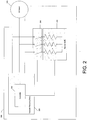
- FIG. 2 illustrates various embodiments of a system 200 for braking an AC motor 210.
- the system 200 includes a variable frequency drive 220, a resistor bank 230 and a three-phase contactor 240 connected to the variable frequency drive 220.
- the variable frequency drive 220 may be configured to control the rotation of AC motor 210 by controlling the frequency of the electrical power supplied to the AC motor.
- the variable frequency drive 220 may include a controller 250 connected to the contactor 240. Any 3-phase AC drive that is equipped with a motor control algorithm as is discussed herein may be used as the variable frequency drive 220.
- the variable frequency drive 220 may increase motor flux at low speeds to increase the energy dissipated in the resistor bank 230, thereby allowing faster deceleration.
- a three-phase contactor 240 may be used to connect the resistor bank 220 to the AC motor 210 when braking is required. Control of the contactor 240 may be established through the variable frequency drive 220.
- FIG. 3 illustrates various embodiments of the variable frequency drive 220 of FIG. 2 .
- the variable frequency drive 220 may comprise a speed regulator 300, a flux regulator 305, a magnetizing current regulator 310, a torque current regulator 315, a DQ-3 ⁇ transform 320, a pulse width modulator 325 and a motor model 330. Each component will be described in more detail below.
- variable frequency drive 220 may receive the flux demand 340 and the speed demand 345 as inputs.
- the flux regulator 305 compensates for the difference between the flux reference and the flux feedback.
- the flux demand 340 and the actual motor flux 360 as provided by the motor model 330 may be compared by the flux regulator 305.
- the output of the flux regulator 305 as determined based upon the comparison of the flux demand 340 and the actual motor flux 360, may be the motor magnetizing current reference 350.
- the speed regulator 300 may compare the speed demand 345 with the motor speed 365 as provided by the motor model 330 and provides the motor torque current reference 355 as an output. In certain embodiments, where the speed demand 345 is less than the actual motor speed 365, thereby indicating a desire to brake the AC motor 210, speed regulator 300 may output a torque current reference 355, thereby indicating the voltage commands being transmitted to the motor may be reduced in order to facilitate braking of the motor.
- the motor model 330 uses the voltage feedback 395 and current feedback 397 from the variable frequency drive 220 output to estimate the motor flux 360, the motor speed 365 and the motor flux angle 370. In addition, the motor model 330 may also determine the magnetizing current 375 and the torque current 380.
- the motor model 330 may be a processor having a memory with a stored set of instructions. Based upon the received voltage feedback 395 and current feedback 397, the motor model may process the feedback information according to the stored instructions to create estimated values for various aspects of AC motor 210, specifically in this example, motor flux 360, motor speed 365, motor flux angle 370, magnetizing current 375, and torque current 380.
- the magnetizing current regulator 310 may compare the magnetizing current reference 350 with the magnetizing current 375 as provided by the motor model 330 to produce a D-axis voltage reference 390.
- the torque current regulator 315 may compare the torque current reference 355 with the torque current 380 as output by the motor model 330 to produce a Q-axis voltage reference 385.
- Both D-axis voltage reference 390 and Q-axis voltage reference 385 may be transformed into a single phase voltage signal at DQ-3 ⁇ transform 320.
- the DQ-3 ⁇ transform 320 may be a mathematical algorithm implemented in software, programmed to operate on the motor flux 370, the magnetizing current 375, and the torque current 380, decomposing the current signals into components parallel to the motor flux (D-axis) and in quadrature to the motor flux (Q-axis). DQ-3 ⁇ transform 320 may further transform the single phase voltage signal into a three-phase voltage single based upon motor flux angle 370. The three-phase voltage signal may be used as a reference for pulse width modulator 325 to generate a pulse width modulator voltage command for controlling semiconductor devices in the power circuit 335.
- variable frequency drive 220 may be implemented on a single processor operably connected to a memory for storing various instructions related to a method for braking a motor.
- the variable frequency drive may receive flux demand 340 and speed demand 345 as inputs, process the information as discussed above to produce the three-phase voltage signal, and based upon the value of this signal, load appropriate instructions from the memory for altering the operation of the AC motor 210.
- FIG. 4 illustrates various embodiments of a method 400 for braking an AC motor.
- the system 200 as discussed above in FIG. 1 and the variable frequency drive 220 as discussed in detail in FIG. 2 may be utilized to implement the method 400.
- the process flow of the method 400 begins when, in response to a user input, the speed demand 345 may be reduced 405 to initiate a speed reduction request for AC motor 210.
- variable frequency drive 220 may detect 410 the change in speed demand as a result of the comparison of motor speed 365 and speed demand made by speed regulator 300. This comparison may result in a negative torque current reference 355, indicating appropriate instructions should be produced or loaded from memory to initiate braking AC motor 210.
- a command e.g., the output of pulse width modulation modulator 325
- variable frequency drive 220 After detecting the reduction 410 in the speed demand 345 and producing a command, the variable frequency drive 220 issues 415 the command to the three-phase contactor 240 to connect the resistor bank 230 to the AC motor 210.
- an approximately balanced resistor bank 230 may be used to limit any fluctuations in motor torque across phases. In some applications where a high level of potential motor torque fluctuations may be acceptable during braking, two phases of the three-phase contactor 240 may be closed, thereby only connecting a portion of the resistor bank 230 to the AC motor 210.
- variable frequency drive 220 may also begin to decrease the torque current 380 to its reverse regeneration limit. It should be noted that after torque current 380 is decreased, and motor speed 365 begins to drop, variable frequency drive 220 may maintain motor flux 360 at a higher value until motor torque reaches approximately zero. In various embodiments, other 2-quadrant drives may be used provided the controller provides fast regulation of the drive current and maintains motor flux during the deceleration process.
- the resistors now operably connected to the AC motor absorb 420 any current generated by the AC motor resulting in the deceleration of the AC motor.
- the variable frequency drive 220 may operate at a small value of regenerative current, the resistors 230 may be able to absorb a significant amount of reverse torque current and allow the AC motor 210 to quickly decelerate.
- the variable frequency drive 220 may maintain motor flux 360 during the deceleration process, the motor voltage may decrease linearly with speed.
- FIG. 5 illustrates exemplary waveforms generated during the deceleration of an AC motor, specifically illustrating motor flux 360, motor speed 365, magnetizing current 375 and torque current 380 as discussed above in FIG. 3 .
- the AC motor was a 4160V, 600hp induction motor, and the deceleration was realized using a 2-quadrant variable frequency drive and a 3-phase resistor bank.
- the resistor bank was sized to operate with a 90% current at a rated motor voltage (e.g., 67 amperes), and deceleration from full speed to zero was completed in less than nine seconds.
- variable frequency drive was able to maintain stable operation (as indicated by a stable value for motor flux 360 ) during deceleration despite the change in impedance caused by the connection of the resistors as well as the change in torque current 380.
- the variable frequency drive was also be able to adequately limit the output current without causing any over-voltage trips in the cells as indicated by the relatively stable values for magnetizing current 375 and torque current 380 while motor flux 365 and motor speed 370 are decreasing quickly, which indicates that the variable frequency drive did not absorb any more power than its normal capability, and that the additional braking power from the motor was dissipated in the resistors.
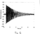
- FIG. 6 illustrates a plot of resistor current through one of the phases during the deceleration corresponding to FIG. 5 .
- the voltage across its terminals may also decrease, thereby decreasing the current through the resistors and reducing braking torque.
- the motor flux may be increased above 10% of the typical value so that higher braking torque may be produced. Higher braking torque may result in a significant reduction in the total time required to stop the motor. It should be noted that the example described above, when used during infrequent braking, it may be possible to raise the motor flux significantly for the duration of a braking interval without motor overheating.
Description
- This application discloses an invention that is related, generally and in various embodiments, to a method and system for braking an AC motor. More specifically, this application is related to braking an AC motor with a variable frequency drive.
- A variable frequency drives are typically devices used to control the rotational speed of an alternating current (AC) motor by controlling the frequency of electrical power delivered to the motor. For example, variable frequency drives, and accompanying control circuits, are described in detail in
U.S. Patent No. 7,327,111 to Rastogi et al. , the disclosure of which is hereby fully incorporated by reference. -
FIG. 1 illustrates an exemplaryvariable frequency drive 100 for providing electrical power tomotor 130.Variable frequency drive 100 includes acontrol circuit 110 and apower circuit 115.Control circuit 110 receivesincoming input commands 105.Input commands 105 may be a request to increase or decrease the speed of themotor 130, which requiresvariable frequency drive 100 to adjust the electrical power output bypower circuit 115 and delivered tomotor 130.Control circuit 110 monitorscurrent feedback 120 andvoltage feedback 125 from the outputted electrical power to determine if any changes should be made to the output to either adjust or maintain conditions atmotor 130. For synchronous motor applications, the variable frequency drive may also include a field supply. The control circuit controls the operation of the power circuit and, for synchronous motor applications, also enables/disables the associated field supply. The power circuit may include a rectifier and an inverter, and provides power to the windings ofmotor 130 connected to thevariable frequency drive 100. For synchronous motor applications, the field supply provides power to an exciter for a motor field circuit. -
Control circuit 110 typically includes a speed regulator, a flux regulator, a magnetizing current regulator, a torque current regulator, a DQ-3Φ transform, a pulse width modulator, and a motor model. The speed regulator provides a torque current reference, and the flux regulator provides a magnetizing current reference. The control circuit compares the magnetizing current reference to a measured magnetizing current, and the magnetizing current regulator determines a Q-axis voltage reference. The control circuit also compares the torque current reference to a measured torque current, and the torque current regulator determines a D-axis voltage reference. Additional feed-forward signals may be added to the D-axis voltage reference and the Q-axis voltage reference to provide a higher dynamic response. The DQ-3Φ transform transforms the Q-axis voltage reference and the D-axis voltage reference from two-phase information into three-phase values. The pulse width modulator converts the three-phase values to switching commands that are sent to the power circuit. The motor model generally utilizes measured voltage and/or current signals to determine motor parameters such as the motor speed, the motor flux, the motor flux angle, etc. For applications where low cost is a business requirement, the motor model may only utilize the variable frequency drive output current or the motor current to determine motor parameters. The motor model also converts measured currents into a magnetizing current component and a torque current component for use in the magnetizing current regulator and the torque current regulator, respectively. The D-axis is aligned with the stator flux. - Many of the functions performed by the
control circuit 110 are implemented in software. The software is written such that calculations are done at two or more different rates so as to save processor execution time. In general, the pulse width modulator operates at the fastest rate and is usually implemented in hardware. The magnetizing current regulator, the torque current regulator, and the DQ-3Φ transform blocks are typically executed at a data rate of 1 - 10 kilohertz so that a fast response of the control is achieved in limiting the output current of the variable frequency drive in case of sudden changes in the load or the output circuit. The speed regulator and the flux regulator typically operate at a slower rate of 100 - 1000 hertz because both motor speed and motor flux change at a much slower rate than the magnetizing current and the torque current. The motor model also is usually computed at this rate. Communications from the control circuit to the outside world, which includes communications to an external device (from the customer), is typically at a rate of 1 - 10 hertz. - In applications where infrequent, but fast, braking of the motor is required, a 4-quadrant drive connected to the motor may be utilized to realize the braking. However, the relatively high cost associated with a 4-quadrant drive renders this approach infeasible for some of such applications.
-
US 2004/0160208 discloses a motor control apparatus for quickly braking an AC motor by absorbing overcurrent produced by the motor in a series of braking resistors by shorting the motor to the braking resistors via a series of brake relays. - The present invention provides a system for braking a motor, comprising at least one resistor, a contactor connected to the at least one resistor and a motor and a variable frequency drive electrically connected to the motor. The variable frequency drive comprises a controller operably connected to the contactor, wherein at least a portion of the contactor closes connecting the at least one resistor to the motor in response to a command from the controller, and wherein variable frequency drive is configured to maintain a high level of motor flux until a motor torque level of approximately zero is output by the motor.
- The present invention also provides a method for braking a motor, the method comprising detecting, by a variable frequency drive, a reduction in speed demand, wherein the reduction initiates deceleration of a motor; issuing a command by the variable frequency drive to close at least one contactor, wherein the closed contactor connects a resistor bank to the motor; issuing a command by the variable frequency drive to maintain a high level of motor flux until a level of motor torque output by the motor is approximately zero; and absorbing, by the resistor bank, deceleration current generated by the motor.
- Various embodiments of the invention are described herein by way of example in conjunction with the following figures.
-
FIG. 1 illustrates an exemplary variable frequency drive. -
FIG. 2 illustrates various embodiments of a system for braking an AC motor. -
FIG. 3 illustrates various embodiments of the variable frequency drive ofFIG. 1 . -
FIG. 4 illustrates various embodiments of a method for braking an AC motor. -
FIG. 5 illustrates exemplary waveforms generated during the deceleration of an AC motor. -
FIG. 6 illustrates a plot of resistor current through one of the phases during the deceleration corresponding toFIG. 5 . -
FIG. 2 illustrates various embodiments of asystem 200 for braking anAC motor 210. Thesystem 200 includes avariable frequency drive 220, aresistor bank 230 and a three-phase contactor 240 connected to thevariable frequency drive 220. As discussed above, thevariable frequency drive 220 may be configured to control the rotation ofAC motor 210 by controlling the frequency of the electrical power supplied to the AC motor. Thevariable frequency drive 220 may include acontroller 250 connected to thecontactor 240. Any 3-phase AC drive that is equipped with a motor control algorithm as is discussed herein may be used as thevariable frequency drive 220. Thevariable frequency drive 220 may increase motor flux at low speeds to increase the energy dissipated in theresistor bank 230, thereby allowing faster deceleration. In various embodiments, a three-phase contactor 240 may be used to connect theresistor bank 220 to theAC motor 210 when braking is required. Control of thecontactor 240 may be established through thevariable frequency drive 220. -
FIG. 3 illustrates various embodiments of thevariable frequency drive 220 ofFIG. 2 . Thevariable frequency drive 220 may comprise aspeed regulator 300, aflux regulator 305, a magnetizing current regulator 310, atorque current regulator 315, a DQ-3Φ transform 320, apulse width modulator 325 and amotor model 330. Each component will be described in more detail below. - As illustrated, the
variable frequency drive 220 may receive theflux demand 340 and thespeed demand 345 as inputs. In various embodiments, theflux regulator 305 compensates for the difference between the flux reference and the flux feedback. Theflux demand 340 and theactual motor flux 360 as provided by themotor model 330 may be compared by theflux regulator 305. The output of theflux regulator 305, as determined based upon the comparison of theflux demand 340 and theactual motor flux 360, may be the motor magnetizingcurrent reference 350. - In various embodiments, the
speed regulator 300 may compare thespeed demand 345 with themotor speed 365 as provided by themotor model 330 and provides the motor torquecurrent reference 355 as an output. In certain embodiments, where thespeed demand 345 is less than theactual motor speed 365, thereby indicating a desire to brake theAC motor 210,speed regulator 300 may output a torquecurrent reference 355, thereby indicating the voltage commands being transmitted to the motor may be reduced in order to facilitate braking of the motor. - In various embodiments, the
motor model 330 uses thevoltage feedback 395 andcurrent feedback 397 from thevariable frequency drive 220 output to estimate themotor flux 360, themotor speed 365 and themotor flux angle 370. In addition, themotor model 330 may also determine the magnetizingcurrent 375 and thetorque current 380. Themotor model 330 may be a processor having a memory with a stored set of instructions. Based upon the receivedvoltage feedback 395 andcurrent feedback 397, the motor model may process the feedback information according to the stored instructions to create estimated values for various aspects ofAC motor 210, specifically in this example,motor flux 360,motor speed 365,motor flux angle 370, magnetizing current 375, andtorque current 380. - The magnetizing current regulator 310 may compare the magnetizing
current reference 350 with the magnetizing current 375 as provided by themotor model 330 to produce a D-axis voltage reference 390. Similarly, thetorque current regulator 315 may compare the torquecurrent reference 355 with the torque current 380 as output by themotor model 330 to produce a Q-axis voltage reference 385. Both D-axis voltage reference 390 and Q-axis voltage reference 385 may be transformed into a single phase voltage signal at DQ-3Φ transform 320. The DQ-3Φ transform 320 may be a mathematical algorithm implemented in software, programmed to operate on themotor flux 370, the magnetizing current 375, and thetorque current 380, decomposing the current signals into components parallel to the motor flux (D-axis) and in quadrature to the motor flux (Q-axis). DQ-3Φ transform 320 may further transform the single phase voltage signal into a three-phase voltage single based uponmotor flux angle 370. The three-phase voltage signal may be used as a reference forpulse width modulator 325 to generate a pulse width modulator voltage command for controlling semiconductor devices in thepower circuit 335. - It should be noted that the components of
variable frequency drive 220 may be implemented on a single processor operably connected to a memory for storing various instructions related to a method for braking a motor. Specifically, the variable frequency drive may receiveflux demand 340 andspeed demand 345 as inputs, process the information as discussed above to produce the three-phase voltage signal, and based upon the value of this signal, load appropriate instructions from the memory for altering the operation of theAC motor 210. -
FIG. 4 illustrates various embodiments of amethod 400 for braking an AC motor. Thesystem 200 as discussed above inFIG. 1 and thevariable frequency drive 220 as discussed in detail inFIG. 2 may be utilized to implement themethod 400. The process flow of themethod 400 begins when, in response to a user input, thespeed demand 345 may be reduced 405 to initiate a speed reduction request forAC motor 210. Uponreduction 405 of thespeed demand 345,variable frequency drive 220 may detect 410 the change in speed demand as a result of the comparison ofmotor speed 365 and speed demand made byspeed regulator 300. This comparison may result in a negative torquecurrent reference 355, indicating appropriate instructions should be produced or loaded from memory to initiate brakingAC motor 210. Based upon the magnitude of the difference in thespeed demand 345 and themotor speed 365, a command (e.g., the output of pulse width modulation modulator 325) may be produced to be sent from thevariable frequency drive 220 tocontactor 240. - After detecting the
reduction 410 in thespeed demand 345 and producing a command, the variable frequency drive 220issues 415 the command to the three-phase contactor 240 to connect theresistor bank 230 to theAC motor 210. It should be noted that an approximatelybalanced resistor bank 230 may be used to limit any fluctuations in motor torque across phases. In some applications where a high level of potential motor torque fluctuations may be acceptable during braking, two phases of the three-phase contactor 240 may be closed, thereby only connecting a portion of theresistor bank 230 to theAC motor 210. - As the three-
phase contactor 240 connects theresistor bank 230 to theAC motor 210, thevariable frequency drive 220 may also begin to decrease the torque current 380 to its reverse regeneration limit. It should be noted that after torque current 380 is decreased, andmotor speed 365 begins to drop,variable frequency drive 220 may maintainmotor flux 360 at a higher value until motor torque reaches approximately zero. In various embodiments, other 2-quadrant drives may be used provided the controller provides fast regulation of the drive current and maintains motor flux during the deceleration process. - After issuing 415 the command to the
contactor 240 to connect theresistor bank 230 to theAC motor 210, the resistors now operably connected to the AC motor absorb 420 any current generated by the AC motor resulting in the deceleration of the AC motor. While thevariable frequency drive 220 may operate at a small value of regenerative current, theresistors 230 may be able to absorb a significant amount of reverse torque current and allow theAC motor 210 to quickly decelerate. As thevariable frequency drive 220 may maintainmotor flux 360 during the deceleration process, the motor voltage may decrease linearly with speed. -
FIG. 5 illustrates exemplary waveforms generated during the deceleration of an AC motor, specifically illustratingmotor flux 360,motor speed 365, magnetizing current 375 and torque current 380 as discussed above inFIG. 3 . For this implementation, the AC motor was a 4160V, 600hp induction motor, and the deceleration was realized using a 2-quadrant variable frequency drive and a 3-phase resistor bank. The resistor bank was sized to operate with a 90% current at a rated motor voltage (e.g., 67 amperes), and deceleration from full speed to zero was completed in less than nine seconds. The variable frequency drive was able to maintain stable operation (as indicated by a stable value for motor flux 360) during deceleration despite the change in impedance caused by the connection of the resistors as well as the change intorque current 380. The variable frequency drive was also be able to adequately limit the output current without causing any over-voltage trips in the cells as indicated by the relatively stable values for magnetizing current 375 and torque current 380 whilemotor flux 365 andmotor speed 370 are decreasing quickly, which indicates that the variable frequency drive did not absorb any more power than its normal capability, and that the additional braking power from the motor was dissipated in the resistors. -
FIG. 6 illustrates a plot of resistor current through one of the phases during the deceleration corresponding toFIG. 5 . According to various embodiments, as the motor slows downs, the voltage across its terminals may also decrease, thereby decreasing the current through the resistors and reducing braking torque. As the variable frequency drive is connected to the motor during the deceleration process, the variable frequency drive may be controlled to apply extra voltage to the motor as its speed decreases. For example, a typical motor can tolerate 10% more voltage at a rated speed. If 10% more voltage is applied at all speeds below the rated value, then the motor may provide 21 % (or 1.12 = 1.21) more braking torque. At lower speeds, the motor core losses are relatively low compared to copper losses. As such, the motor flux may be increased above 10% of the typical value so that higher braking torque may be produced. Higher braking torque may result in a significant reduction in the total time required to stop the motor. It should be noted that the example described above, when used during infrequent braking, it may be possible to raise the motor flux significantly for the duration of a braking interval without motor overheating. - While several embodiments of the invention have been described herein by way of example, those skilled in the art will appreciate that various modifications, alterations and adaptations to the described embodiments may be realized without departing from the scope of the invention. For example, although the
method 400 is described with reference to a particular sequence, those skilled in the art will appreciate that some steps may occur in a different sequence, some steps may occur concurrently with other steps, and some steps may occur on a periodic or continuous basis.
Claims (14)
- A system for braking a motor, comprising:at least one resistor (230);a contactor (240) connected to the at least one resistor and a motor (210); anda variable frequency drive (220) electrically connected to the motor, wherein the variable frequency drive comprises a controller (250) operably connected to the contactor, wherein at least a portion of the contactor closes connecting the at least one resistor to the motor in response to a command from the controller, and wherein variable frequency drive is configured to maintain a high level of motor flux until a motor torque level of approximately zero is output by the motor.
- The system of claim 1, wherein the variable frequency drive further comprises a motor model (330) that receives voltage feedback (395) and current feedback (397) from the variable frequency drive, processes the voltage feedback and current feedback, and outputs motor flux (360), motor speed (365), magnetizing current (375), torque current and motor flux angle (370).
- The system of claim 2, wherein the variable frequency drive further comprises a speed regulator (300) configured to process the motor speed and producing a reference torque current (355).
- The system of claim 3, wherein the variable frequency drive further comprises a flux regulator (305) configured to process the motor flux and produce a reference magnetizing current (350).
- The system of claim 4, wherein the variable frequency drive further comprises a torque current regulator (315) configured to process both the reference torque current and the torque current (380) and produce a reference Q-Axis voltage (385) as well as a magnetizing current regulator (310) configured to process both the reference magnetizing current and the magnetizing current (375) and produce a reference D-Axis voltage (390).
- The system of claim 5, wherein the variable frequency drive further comprises a DQ-3Φ transform (320) configured to process both the reference Q-Axis voltage and the reference D-Axis voltage to produce a three phase electrical output.
- The system of claim 6, wherein the variable frequency drive further comprises a pulse width modulation modulator (325) configured to produce pulse width modulated voltage commands.
- The system according to any preceding claim, wherein the at least one resistor comprises a resistor bank (230) having a plurality of phases, and the contactor has a plurality of phases, wherein each phase of the contactor is connected to one phase of the resistor bank.
- The system of any preceding claim, wherein the contactor is a three-phase contactor.
- The system of claim 9, wherein the at least one resistor is a three-phase resistor bank.
- The system of any preceding claim, wherein controller commands instruct the contactor to close, thereby connecting the resistor bank to the motor.
- A method for braking a motor (210), the method comprising:detecting, by a variable frequency drive (220), a reduction in speed demand (345), wherein the reduction initiates deceleration of a motor;issuing a command by the variable frequency drive to close at least one contactor (240), wherein the closed contactor connects a resistor bank (230) to the motor;issuing a command by the variable frequency drive to maintain a high level of motor flux until a level of motor torque output by the motor is approximately zero; andabsorbing, by the resistor bank, deceleration current generated by the motor.
- The method of claim 12, wherein the issuing a command comprises issuing a command by the variable frequency drive to close at least two phases of a three-phase contactor (240), wherein the at least two closed phases of the three-phase contactor connect at least two phases of a resistor bank (230) to the motor.
- The method of claim 13, wherein a determination to close the three-phase contactor is made by the variable frequency drive based upon the detected reduction in speed demand.
Applications Claiming Priority (3)
| Application Number | Priority Date | Filing Date | Title |
|---|---|---|---|
| US3034208P | 2008-02-21 | 2008-02-21 | |
| US12/389,935 US8134316B2 (en) | 2008-02-21 | 2009-02-20 | Method for braking an AC motor |
| PCT/US2009/001137 WO2009105276A1 (en) | 2008-02-21 | 2009-02-23 | Method and system for braking an ac motor |
Publications (2)
| Publication Number | Publication Date |
|---|---|
| EP2243214A1 EP2243214A1 (en) | 2010-10-27 |
| EP2243214B1 true EP2243214B1 (en) | 2016-12-07 |
Family
ID=42752491
Family Applications (1)
| Application Number | Title | Priority Date | Filing Date |
|---|---|---|---|
| EP09712911.8A Not-in-force EP2243214B1 (en) | 2008-02-21 | 2009-02-23 | Method and system for braking an ac motor |
Country Status (7)
| Country | Link |
|---|---|
| EP (1) | EP2243214B1 (en) |
| JP (1) | JP5455934B2 (en) |
| CN (1) | CN101986798B (en) |
| BR (1) | BRPI0907940B1 (en) |
| CA (1) | CA2714698C (en) |
| MX (1) | MX2010009049A (en) |
| WO (1) | WO2009105276A1 (en) |
Families Citing this family (4)
| Publication number | Priority date | Publication date | Assignee | Title |
|---|---|---|---|---|
| CN103580499A (en) * | 2012-08-09 | 2014-02-12 | 成都进界科技有限公司 | Single-damper single-resistor star-connection non-vibration brake frequency conversion device |
| CN103633893A (en) * | 2012-08-27 | 2014-03-12 | 成都酷玩网络科技有限公司 | Single-damping mixed star connection vibration-free braking frequency conversion apparatus |
| US10505488B2 (en) * | 2016-01-14 | 2019-12-10 | Siemens Aktiengesellschaft | Systems and method for controlling electrodynamic machines with a variable frequency drive |
| CN106124872B (en) * | 2016-08-31 | 2019-03-19 | 南京康尼电子科技有限公司 | A kind of open phases of three-phase power source, detection of power loss system and braking method |
Family Cites Families (12)
| Publication number | Priority date | Publication date | Assignee | Title |
|---|---|---|---|---|
| US4093900A (en) * | 1976-08-11 | 1978-06-06 | General Electric Company | Dynamic brake blending for an inverter propulsion system |
| US4426606A (en) * | 1982-11-08 | 1984-01-17 | Sanyo Denki Co., Ltd. | Emergency stop device for brushless motors |
| FI112733B (en) * | 1994-09-30 | 2003-12-31 | Kone Corp | Method and apparatus for braking a synchronous motor |
| JPH08317678A (en) * | 1995-05-18 | 1996-11-29 | Fanuc Ltd | Dynamic brake for polyphase synchronous electric motor using inverter |
| US5992950A (en) * | 1998-03-30 | 1999-11-30 | General Electric Company | Controlled stop function for locomotives |
| US6137258A (en) * | 1998-10-26 | 2000-10-24 | General Electric Company | System for speed-sensorless control of an induction machine |
| JP3489022B2 (en) * | 1999-03-18 | 2004-01-19 | 株式会社安川電機 | Dynamic brake circuit and semiconductor inverter device |
| US7066034B2 (en) * | 2001-11-12 | 2006-06-27 | International Rectifier Corporation | Start-up method and system for permanent magnet synchronous motor drive |
| KR100488523B1 (en) | 2003-02-14 | 2005-05-11 | 삼성전자주식회사 | Motor control apparatus and control method thereof |
| KR100488528B1 (en) * | 2003-05-16 | 2005-05-11 | 삼성전자주식회사 | Power supply device for motor |
| US7012392B2 (en) * | 2004-02-06 | 2006-03-14 | Honeywell International Inc. | Multi-stage dynamic braking resistor network |
| US7327111B2 (en) * | 2005-08-12 | 2008-02-05 | Siemens Energy & Automation, Inc. | System and method for parallel control of variable frequency drives |
-
2009
- 2009-02-23 CA CA2714698A patent/CA2714698C/en active Active
- 2009-02-23 WO PCT/US2009/001137 patent/WO2009105276A1/en active Application Filing
- 2009-02-23 BR BRPI0907940-8A patent/BRPI0907940B1/en not_active IP Right Cessation
- 2009-02-23 CN CN200980105844.XA patent/CN101986798B/en active Active
- 2009-02-23 JP JP2010547652A patent/JP5455934B2/en not_active Expired - Fee Related
- 2009-02-23 MX MX2010009049A patent/MX2010009049A/en active IP Right Grant
- 2009-02-23 EP EP09712911.8A patent/EP2243214B1/en not_active Not-in-force
Non-Patent Citations (1)
| Title |
|---|
| None * |
Also Published As
| Publication number | Publication date |
|---|---|
| CN101986798B (en) | 2014-10-01 |
| WO2009105276A1 (en) | 2009-08-27 |
| MX2010009049A (en) | 2010-09-10 |
| CN101986798A (en) | 2011-03-16 |
| CA2714698A1 (en) | 2009-08-27 |
| BRPI0907940A2 (en) | 2015-07-28 |
| CA2714698C (en) | 2014-09-09 |
| JP2011514128A (en) | 2011-04-28 |
| JP5455934B2 (en) | 2014-03-26 |
| EP2243214A1 (en) | 2010-10-27 |
| BRPI0907940B1 (en) | 2019-07-16 |
Similar Documents
| Publication | Publication Date | Title |
|---|---|---|
| EP2697902B1 (en) | System and method for fast start-up of an induction motor | |
| US7477037B2 (en) | Method for parallel control of series-cell based drives | |
| EP1922806B1 (en) | System and method for parallel control of variable frequency drives | |
| US4767976A (en) | Control system for PWM inverter | |
| ES2618153T3 (en) | Method and system to brake an AC motor | |
| WO2010026699A1 (en) | Power conversion device | |
| US6690139B1 (en) | Method and apparatus to limit motor current at low frequencies | |
| US6876169B2 (en) | Method and controller for field weakening operation of AC machines | |
| US8134316B2 (en) | Method for braking an AC motor | |
| EP2243214B1 (en) | Method and system for braking an ac motor | |
| JP2002233180A (en) | Power converter | |
| JP4300831B2 (en) | Braking method and inverter apparatus for inverter-driven induction motor | |
| JP2007221864A (en) | Inverter controller of ac motor | |
| WO2014141527A1 (en) | Motor control device | |
| EP2165409B1 (en) | System and method for limiting input voltage to a power delivery system having regeneration capability | |
| EP2571157B1 (en) | Method and device for controlling power to an electric machine | |
| EP3229364B1 (en) | Inverter | |
| JPH08126400A (en) | Vector controller for induction motor | |
| JP2001238455A (en) | Multiple power converter | |
| JP2023122381A (en) | Driving system and control device | |
| JPH08298796A (en) | Method and device for controlling permanent magnet type electric motor | |
| KR20220131678A (en) | Apparatus for controlling inverter | |
| KR20060006637A (en) | Device and method for stopping induction motor | |
| CN114766078A (en) | Inverter control device | |
| KR20240044128A (en) | Motor driving apparatus and method controlling for the same |
Legal Events
| Date | Code | Title | Description |
|---|---|---|---|
| PUAI | Public reference made under article 153(3) epc to a published international application that has entered the european phase |
Free format text: ORIGINAL CODE: 0009012 |
|
| 17P | Request for examination filed |
Effective date: 20100625 |
|
| AK | Designated contracting states |
Kind code of ref document: A1 Designated state(s): AT BE BG CH CY CZ DE DK EE ES FI FR GB GR HR HU IE IS IT LI LT LU LV MC MK MT NL NO PL PT RO SE SI SK TR |
|
| AX | Request for extension of the european patent |
Extension state: AL BA RS |
|
| DAX | Request for extension of the european patent (deleted) | ||
| RAP1 | Party data changed (applicant data changed or rights of an application transferred) |
Owner name: SIEMENS AKTIENGESELLSCHAFT |
|
| GRAP | Despatch of communication of intention to grant a patent |
Free format text: ORIGINAL CODE: EPIDOSNIGR1 |
|
| RIC1 | Information provided on ipc code assigned before grant |
Ipc: H02P 21/14 20060101ALI20160415BHEP Ipc: H02P 21/36 20160101ALI20160415BHEP Ipc: H02P 3/22 20060101AFI20160415BHEP |
|
| INTG | Intention to grant announced |
Effective date: 20160510 |
|
| RIN1 | Information on inventor provided before grant (corrected) |
Inventor name: OSMAN, RICHARD H. Inventor name: RASTOGI, MUKUL |
|
| GRAJ | Information related to disapproval of communication of intention to grant by the applicant or resumption of examination proceedings by the epo deleted |
Free format text: ORIGINAL CODE: EPIDOSDIGR1 |
|
| GRAS | Grant fee paid |
Free format text: ORIGINAL CODE: EPIDOSNIGR3 |
|
| INTC | Intention to grant announced (deleted) | ||
| GRAP | Despatch of communication of intention to grant a patent |
Free format text: ORIGINAL CODE: EPIDOSNIGR1 |
|
| INTG | Intention to grant announced |
Effective date: 20160928 |
|
| GRAA | (expected) grant |
Free format text: ORIGINAL CODE: 0009210 |
|
| STAA | Information on the status of an ep patent application or granted ep patent |
Free format text: STATUS: THE PATENT HAS BEEN GRANTED |
|
| AK | Designated contracting states |
Kind code of ref document: B1 Designated state(s): AT BE BG CH CY CZ DE DK EE ES FI FR GB GR HR HU IE IS IT LI LT LU LV MC MK MT NL NO PL PT RO SE SI SK TR |
|
| REG | Reference to a national code |
Ref country code: GB Ref legal event code: FG4D |
|
| REG | Reference to a national code |
Ref country code: AT Ref legal event code: REF Ref document number: 852493 Country of ref document: AT Kind code of ref document: T Effective date: 20161215 Ref country code: CH Ref legal event code: EP |
|
| REG | Reference to a national code |
Ref country code: IE Ref legal event code: FG4D |
|
| REG | Reference to a national code |
Ref country code: CH Ref legal event code: NV Representative=s name: SIEMENS SCHWEIZ AG, CH |
|
| REG | Reference to a national code |
Ref country code: DE Ref legal event code: R096 Ref document number: 602009042900 Country of ref document: DE |
|
| REG | Reference to a national code |
Ref country code: FR Ref legal event code: PLFP Year of fee payment: 9 |
|
| PG25 | Lapsed in a contracting state [announced via postgrant information from national office to epo] |
Ref country code: LV Free format text: LAPSE BECAUSE OF FAILURE TO SUBMIT A TRANSLATION OF THE DESCRIPTION OR TO PAY THE FEE WITHIN THE PRESCRIBED TIME-LIMIT Effective date: 20161207 |
|
| REG | Reference to a national code |
Ref country code: NL Ref legal event code: FP |
|
| REG | Reference to a national code |
Ref country code: NO Ref legal event code: T2 Effective date: 20161207 |
|
| REG | Reference to a national code |
Ref country code: LT Ref legal event code: MG4D |
|
| PG25 | Lapsed in a contracting state [announced via postgrant information from national office to epo] |
Ref country code: SE Free format text: LAPSE BECAUSE OF FAILURE TO SUBMIT A TRANSLATION OF THE DESCRIPTION OR TO PAY THE FEE WITHIN THE PRESCRIBED TIME-LIMIT Effective date: 20161207 Ref country code: GR Free format text: LAPSE BECAUSE OF FAILURE TO SUBMIT A TRANSLATION OF THE DESCRIPTION OR TO PAY THE FEE WITHIN THE PRESCRIBED TIME-LIMIT Effective date: 20170308 Ref country code: LT Free format text: LAPSE BECAUSE OF FAILURE TO SUBMIT A TRANSLATION OF THE DESCRIPTION OR TO PAY THE FEE WITHIN THE PRESCRIBED TIME-LIMIT Effective date: 20161207 |
|
| REG | Reference to a national code |
Ref country code: AT Ref legal event code: MK05 Ref document number: 852493 Country of ref document: AT Kind code of ref document: T Effective date: 20161207 |
|
| PG25 | Lapsed in a contracting state [announced via postgrant information from national office to epo] |
Ref country code: BE Free format text: LAPSE BECAUSE OF NON-PAYMENT OF DUE FEES Effective date: 20170228 Ref country code: HR Free format text: LAPSE BECAUSE OF FAILURE TO SUBMIT A TRANSLATION OF THE DESCRIPTION OR TO PAY THE FEE WITHIN THE PRESCRIBED TIME-LIMIT Effective date: 20161207 Ref country code: FI Free format text: LAPSE BECAUSE OF FAILURE TO SUBMIT A TRANSLATION OF THE DESCRIPTION OR TO PAY THE FEE WITHIN THE PRESCRIBED TIME-LIMIT Effective date: 20161207 |
|
| REG | Reference to a national code |
Ref country code: ES Ref legal event code: FG2A Ref document number: 2618153 Country of ref document: ES Kind code of ref document: T3 Effective date: 20170621 |
|
| PG25 | Lapsed in a contracting state [announced via postgrant information from national office to epo] |
Ref country code: CZ Free format text: LAPSE BECAUSE OF FAILURE TO SUBMIT A TRANSLATION OF THE DESCRIPTION OR TO PAY THE FEE WITHIN THE PRESCRIBED TIME-LIMIT Effective date: 20161207 Ref country code: SK Free format text: LAPSE BECAUSE OF FAILURE TO SUBMIT A TRANSLATION OF THE DESCRIPTION OR TO PAY THE FEE WITHIN THE PRESCRIBED TIME-LIMIT Effective date: 20161207 Ref country code: RO Free format text: LAPSE BECAUSE OF FAILURE TO SUBMIT A TRANSLATION OF THE DESCRIPTION OR TO PAY THE FEE WITHIN THE PRESCRIBED TIME-LIMIT Effective date: 20161207 Ref country code: EE Free format text: LAPSE BECAUSE OF FAILURE TO SUBMIT A TRANSLATION OF THE DESCRIPTION OR TO PAY THE FEE WITHIN THE PRESCRIBED TIME-LIMIT Effective date: 20161207 Ref country code: IS Free format text: LAPSE BECAUSE OF FAILURE TO SUBMIT A TRANSLATION OF THE DESCRIPTION OR TO PAY THE FEE WITHIN THE PRESCRIBED TIME-LIMIT Effective date: 20170407 |
|
| RAP2 | Party data changed (patent owner data changed or rights of a patent transferred) |
Owner name: SIEMENS AKTIENGESELLSCHAFT |
|
| PG25 | Lapsed in a contracting state [announced via postgrant information from national office to epo] |
Ref country code: PT Free format text: LAPSE BECAUSE OF FAILURE TO SUBMIT A TRANSLATION OF THE DESCRIPTION OR TO PAY THE FEE WITHIN THE PRESCRIBED TIME-LIMIT Effective date: 20170407 Ref country code: BG Free format text: LAPSE BECAUSE OF FAILURE TO SUBMIT A TRANSLATION OF THE DESCRIPTION OR TO PAY THE FEE WITHIN THE PRESCRIBED TIME-LIMIT Effective date: 20170307 Ref country code: BE Free format text: LAPSE BECAUSE OF FAILURE TO SUBMIT A TRANSLATION OF THE DESCRIPTION OR TO PAY THE FEE WITHIN THE PRESCRIBED TIME-LIMIT Effective date: 20161207 Ref country code: AT Free format text: LAPSE BECAUSE OF FAILURE TO SUBMIT A TRANSLATION OF THE DESCRIPTION OR TO PAY THE FEE WITHIN THE PRESCRIBED TIME-LIMIT Effective date: 20161207 Ref country code: PL Free format text: LAPSE BECAUSE OF FAILURE TO SUBMIT A TRANSLATION OF THE DESCRIPTION OR TO PAY THE FEE WITHIN THE PRESCRIBED TIME-LIMIT Effective date: 20161207 |
|
| REG | Reference to a national code |
Ref country code: DE Ref legal event code: R097 Ref document number: 602009042900 Country of ref document: DE |
|
| PG25 | Lapsed in a contracting state [announced via postgrant information from national office to epo] |
Ref country code: MC Free format text: LAPSE BECAUSE OF FAILURE TO SUBMIT A TRANSLATION OF THE DESCRIPTION OR TO PAY THE FEE WITHIN THE PRESCRIBED TIME-LIMIT Effective date: 20161207 |
|
| REG | Reference to a national code |
Ref country code: CH Ref legal event code: PCOW Free format text: NEW ADDRESS: WERNER-VON-SIEMENS-STRASSE 1, 80333 MUENCHEN (DE) |
|
| PLBE | No opposition filed within time limit |
Free format text: ORIGINAL CODE: 0009261 |
|
| STAA | Information on the status of an ep patent application or granted ep patent |
Free format text: STATUS: NO OPPOSITION FILED WITHIN TIME LIMIT |
|
| 26N | No opposition filed |
Effective date: 20170908 |
|
| REG | Reference to a national code |
Ref country code: IE Ref legal event code: MM4A |
|
| PG25 | Lapsed in a contracting state [announced via postgrant information from national office to epo] |
Ref country code: SI Free format text: LAPSE BECAUSE OF FAILURE TO SUBMIT A TRANSLATION OF THE DESCRIPTION OR TO PAY THE FEE WITHIN THE PRESCRIBED TIME-LIMIT Effective date: 20161207 Ref country code: DK Free format text: LAPSE BECAUSE OF FAILURE TO SUBMIT A TRANSLATION OF THE DESCRIPTION OR TO PAY THE FEE WITHIN THE PRESCRIBED TIME-LIMIT Effective date: 20161207 |
|
| PG25 | Lapsed in a contracting state [announced via postgrant information from national office to epo] |
Ref country code: LU Free format text: LAPSE BECAUSE OF NON-PAYMENT OF DUE FEES Effective date: 20170223 |
|
| REG | Reference to a national code |
Ref country code: FR Ref legal event code: PLFP Year of fee payment: 10 |
|
| PG25 | Lapsed in a contracting state [announced via postgrant information from national office to epo] |
Ref country code: IE Free format text: LAPSE BECAUSE OF NON-PAYMENT OF DUE FEES Effective date: 20170223 |
|
| PG25 | Lapsed in a contracting state [announced via postgrant information from national office to epo] |
Ref country code: MT Free format text: LAPSE BECAUSE OF NON-PAYMENT OF DUE FEES Effective date: 20170223 |
|
| PG25 | Lapsed in a contracting state [announced via postgrant information from national office to epo] |
Ref country code: HU Free format text: LAPSE BECAUSE OF FAILURE TO SUBMIT A TRANSLATION OF THE DESCRIPTION OR TO PAY THE FEE WITHIN THE PRESCRIBED TIME-LIMIT; INVALID AB INITIO Effective date: 20090223 |
|
| PG25 | Lapsed in a contracting state [announced via postgrant information from national office to epo] |
Ref country code: CY Free format text: LAPSE BECAUSE OF NON-PAYMENT OF DUE FEES Effective date: 20161207 |
|
| PG25 | Lapsed in a contracting state [announced via postgrant information from national office to epo] |
Ref country code: MK Free format text: LAPSE BECAUSE OF FAILURE TO SUBMIT A TRANSLATION OF THE DESCRIPTION OR TO PAY THE FEE WITHIN THE PRESCRIBED TIME-LIMIT Effective date: 20161207 |
|
| PG25 | Lapsed in a contracting state [announced via postgrant information from national office to epo] |
Ref country code: TR Free format text: LAPSE BECAUSE OF FAILURE TO SUBMIT A TRANSLATION OF THE DESCRIPTION OR TO PAY THE FEE WITHIN THE PRESCRIBED TIME-LIMIT Effective date: 20161207 |
|
| PGFP | Annual fee paid to national office [announced via postgrant information from national office to epo] |
Ref country code: NL Payment date: 20200205 Year of fee payment: 12 Ref country code: GB Payment date: 20200206 Year of fee payment: 12 Ref country code: IT Payment date: 20200224 Year of fee payment: 12 Ref country code: NO Payment date: 20200224 Year of fee payment: 12 |
|
| PGFP | Annual fee paid to national office [announced via postgrant information from national office to epo] |
Ref country code: FR Payment date: 20200211 Year of fee payment: 12 |
|
| PGFP | Annual fee paid to national office [announced via postgrant information from national office to epo] |
Ref country code: ES Payment date: 20200522 Year of fee payment: 12 Ref country code: DE Payment date: 20200420 Year of fee payment: 12 Ref country code: CH Payment date: 20200504 Year of fee payment: 12 |
|
| REG | Reference to a national code |
Ref country code: DE Ref legal event code: R119 Ref document number: 602009042900 Country of ref document: DE |
|
| REG | Reference to a national code |
Ref country code: NO Ref legal event code: MMEP |
|
| GBPC | Gb: european patent ceased through non-payment of renewal fee |
Effective date: 20210223 |
|
| PG25 | Lapsed in a contracting state [announced via postgrant information from national office to epo] |
Ref country code: CH Free format text: LAPSE BECAUSE OF NON-PAYMENT OF DUE FEES Effective date: 20210228 Ref country code: LI Free format text: LAPSE BECAUSE OF NON-PAYMENT OF DUE FEES Effective date: 20210228 |
|
| PG25 | Lapsed in a contracting state [announced via postgrant information from national office to epo] |
Ref country code: NO Free format text: LAPSE BECAUSE OF NON-PAYMENT OF DUE FEES Effective date: 20210228 |
|
| REG | Reference to a national code |
Ref country code: NL Ref legal event code: MM Effective date: 20210301 |
|
| PG25 | Lapsed in a contracting state [announced via postgrant information from national office to epo] |
Ref country code: NL Free format text: LAPSE BECAUSE OF NON-PAYMENT OF DUE FEES Effective date: 20210301 |
|
| PG25 | Lapsed in a contracting state [announced via postgrant information from national office to epo] |
Ref country code: FR Free format text: LAPSE BECAUSE OF NON-PAYMENT OF DUE FEES Effective date: 20210228 Ref country code: GB Free format text: LAPSE BECAUSE OF NON-PAYMENT OF DUE FEES Effective date: 20210223 Ref country code: DE Free format text: LAPSE BECAUSE OF NON-PAYMENT OF DUE FEES Effective date: 20210901 |
|
| PG25 | Lapsed in a contracting state [announced via postgrant information from national office to epo] |
Ref country code: IT Free format text: LAPSE BECAUSE OF NON-PAYMENT OF DUE FEES Effective date: 20210223 |
|
| REG | Reference to a national code |
Ref country code: ES Ref legal event code: FD2A Effective date: 20220513 |
|
| PG25 | Lapsed in a contracting state [announced via postgrant information from national office to epo] |
Ref country code: ES Free format text: LAPSE BECAUSE OF NON-PAYMENT OF DUE FEES Effective date: 20210224 |