EP2243145B1 - Field-controlled composite insulator - Google Patents
Field-controlled composite insulator Download PDFInfo
- Publication number
- EP2243145B1 EP2243145B1 EP09709505A EP09709505A EP2243145B1 EP 2243145 B1 EP2243145 B1 EP 2243145B1 EP 09709505 A EP09709505 A EP 09709505A EP 09709505 A EP09709505 A EP 09709505A EP 2243145 B1 EP2243145 B1 EP 2243145B1
- Authority
- EP
- European Patent Office
- Prior art keywords
- field control
- layer
- insulator
- control layer
- particles
- Prior art date
- Legal status (The legal status is an assumption and is not a legal conclusion. Google has not performed a legal analysis and makes no representation as to the accuracy of the status listed.)
- Active
Links
- 239000012212 insulator Substances 0.000 title claims description 92
- 239000002131 composite material Substances 0.000 title claims description 29
- 239000010410 layer Substances 0.000 claims description 164
- 239000002245 particle Substances 0.000 claims description 38
- 239000000463 material Substances 0.000 claims description 24
- 239000011241 protective layer Substances 0.000 claims description 23
- 230000005684 electric field Effects 0.000 claims description 13
- 239000000945 filler Substances 0.000 claims description 13
- 230000000694 effects Effects 0.000 claims description 8
- 238000004519 manufacturing process Methods 0.000 claims description 7
- 239000000203 mixture Substances 0.000 claims description 7
- 238000000034 method Methods 0.000 claims description 6
- 238000011049 filling Methods 0.000 claims description 4
- 239000004033 plastic Substances 0.000 claims description 4
- 229920003023 plastic Polymers 0.000 claims description 4
- 239000011810 insulating material Substances 0.000 claims description 3
- 238000005325 percolation Methods 0.000 claims description 3
- 238000010438 heat treatment Methods 0.000 claims description 2
- 229920001971 elastomer Polymers 0.000 claims 1
- 239000000806 elastomer Substances 0.000 claims 1
- 239000004020 conductor Substances 0.000 description 7
- 230000007704 transition Effects 0.000 description 7
- 229920001296 polysiloxane Polymers 0.000 description 4
- 239000011152 fibreglass Substances 0.000 description 3
- 239000002184 metal Substances 0.000 description 3
- 229920000642 polymer Polymers 0.000 description 3
- 239000004065 semiconductor Substances 0.000 description 3
- GWEVSGVZZGPLCZ-UHFFFAOYSA-N Titan oxide Chemical compound O=[Ti]=O GWEVSGVZZGPLCZ-UHFFFAOYSA-N 0.000 description 2
- 230000015572 biosynthetic process Effects 0.000 description 2
- 238000000576 coating method Methods 0.000 description 2
- 239000011231 conductive filler Substances 0.000 description 2
- 230000006378 damage Effects 0.000 description 2
- 238000009826 distribution Methods 0.000 description 2
- 238000001035 drying Methods 0.000 description 2
- 239000003822 epoxy resin Substances 0.000 description 2
- 230000003628 erosive effect Effects 0.000 description 2
- 229920000647 polyepoxide Polymers 0.000 description 2
- 239000000843 powder Substances 0.000 description 2
- 238000007669 thermal treatment Methods 0.000 description 2
- 229920002430 Fibre-reinforced plastic Polymers 0.000 description 1
- 206010063493 Premature ageing Diseases 0.000 description 1
- 208000032038 Premature aging Diseases 0.000 description 1
- 229910003087 TiOx Inorganic materials 0.000 description 1
- 230000032683 aging Effects 0.000 description 1
- 239000012080 ambient air Substances 0.000 description 1
- 229910002113 barium titanate Inorganic materials 0.000 description 1
- 239000007767 bonding agent Substances 0.000 description 1
- 239000006229 carbon black Substances 0.000 description 1
- 229920001577 copolymer Polymers 0.000 description 1
- 239000012792 core layer Substances 0.000 description 1
- 238000005520 cutting process Methods 0.000 description 1
- 230000001419 dependent effect Effects 0.000 description 1
- 238000001125 extrusion Methods 0.000 description 1
- 239000011151 fibre-reinforced plastic Substances 0.000 description 1
- LNEPOXFFQSENCJ-UHFFFAOYSA-N haloperidol Chemical compound C1CC(O)(C=2C=CC(Cl)=CC=2)CCN1CCCC(=O)C1=CC=C(F)C=C1 LNEPOXFFQSENCJ-UHFFFAOYSA-N 0.000 description 1
- 238000009434 installation Methods 0.000 description 1
- 238000009413 insulation Methods 0.000 description 1
- 230000003993 interaction Effects 0.000 description 1
- 230000002262 irrigation Effects 0.000 description 1
- 238000003973 irrigation Methods 0.000 description 1
- 239000007769 metal material Substances 0.000 description 1
- 229910044991 metal oxide Inorganic materials 0.000 description 1
- 150000004706 metal oxides Chemical class 0.000 description 1
- 239000002923 metal particle Substances 0.000 description 1
- 239000003973 paint Substances 0.000 description 1
- 229920001225 polyester resin Polymers 0.000 description 1
- 239000004645 polyester resin Substances 0.000 description 1
- 238000002360 preparation method Methods 0.000 description 1
- 238000000926 separation method Methods 0.000 description 1
- 229920002379 silicone rubber Polymers 0.000 description 1
- 239000004945 silicone rubber Substances 0.000 description 1
- 230000035882 stress Effects 0.000 description 1
- 239000000725 suspension Substances 0.000 description 1
- 229920001187 thermosetting polymer Polymers 0.000 description 1
- HLLICFJUWSZHRJ-UHFFFAOYSA-N tioxidazole Chemical compound CCCOC1=CC=C2N=C(NC(=O)OC)SC2=C1 HLLICFJUWSZHRJ-UHFFFAOYSA-N 0.000 description 1
Images


Classifications
-
- H—ELECTRICITY
- H01—ELECTRIC ELEMENTS
- H01B—CABLES; CONDUCTORS; INSULATORS; SELECTION OF MATERIALS FOR THEIR CONDUCTIVE, INSULATING OR DIELECTRIC PROPERTIES
- H01B17/00—Insulators or insulating bodies characterised by their form
- H01B17/32—Single insulators consisting of two or more dissimilar insulating bodies
- H01B17/325—Single insulators consisting of two or more dissimilar insulating bodies comprising a fibre-reinforced insulating core member
-
- H—ELECTRICITY
- H01—ELECTRIC ELEMENTS
- H01B—CABLES; CONDUCTORS; INSULATORS; SELECTION OF MATERIALS FOR THEIR CONDUCTIVE, INSULATING OR DIELECTRIC PROPERTIES
- H01B17/00—Insulators or insulating bodies characterised by their form
- H01B17/42—Means for obtaining improved distribution of voltage; Protection against arc discharges
-
- Y—GENERAL TAGGING OF NEW TECHNOLOGICAL DEVELOPMENTS; GENERAL TAGGING OF CROSS-SECTIONAL TECHNOLOGIES SPANNING OVER SEVERAL SECTIONS OF THE IPC; TECHNICAL SUBJECTS COVERED BY FORMER USPC CROSS-REFERENCE ART COLLECTIONS [XRACs] AND DIGESTS
- Y10—TECHNICAL SUBJECTS COVERED BY FORMER USPC
- Y10T—TECHNICAL SUBJECTS COVERED BY FORMER US CLASSIFICATION
- Y10T29/00—Metal working
- Y10T29/49—Method of mechanical manufacture
- Y10T29/49002—Electrical device making
- Y10T29/49227—Insulator making
Definitions
- the invention relates to a field-controlled composite insulator comprising a rod or tube as insulator core made of fiber-reinforced plastic, which is coated with a screen cover and equipped at its ends with fittings.
- the materials of an insulator are heavily loaded by the inhomogeneous distribution of the electric field across its surface.
- One of the causes lies in the structural design of an insulator.
- the field strength changes due to the transition from the insulating materials of the screens and the insulator core to a metallic material, because of the transition to ground potential at the mast crossbar or conductor potential, where the conductors are attached.
- the so-called geometric field control can be used. By rounding corners and edges, the geometry of the workpieces, in particular the parts carrying the tension, is defused.
- insulating materials such as plastics such as epoxy resins and polymers are applied with deposits of dielectric and / or ferroelectric materials as field control layers.
- a composite insulator whose screen element and optionally the core are each made of a semiconducting material.
- the semiconductor capability of the shield shell and the core are the same size at each point of the insulator.
- the screen cover must be additionally coated with a protective layer.
- the field control layer of the composite insulator according to the invention accordingly comprises a layer in which the proportion of the particles influencing the electric field is different over the length of the layer.
- the galvanic contact between the field control layer and the fitting can be produced for example by conductive ink, metal rings or wire mesh.
- the field control layer is surrounded by a protective layer or directly by the screens extruded seamlessly on the core.
- the insulator core as a pipe or rod is usually made of a fiberglass-reinforced thermoset such as epoxy or polyester resin.
- the invention is suitable for all types of composite insulators, in particular for suspension insulators, post insulators or bushing insulators.
- the field of application starts at high voltages above 1 kV and is particularly effective at voltages above 72.5 kV.
- the field control layer is usually made of the same material as the protective layer covering it.
- the protective layer can also be advantageous from a higher erosionsund Kriechstromfesten material.
- the protective layer is in any case made of a material with high insulation properties. Materials with these properties are elastomeric materials, for example, polymeric plastics such as silicone rubber (HTV) of hardness classes Shore A 60 to 90 or ethylene-propylene copolymer (EPM).
- HTV silicone rubber
- EPM ethylene-propylene copolymer
- the field control can be resistive or capacitive or in combination with each other.
- the material of the field control layer is filled with particles as filler, which cause the field control.
- a field control layer with ohmic conductive (conductive) and / or semiconducting (semiconductive) fillers is provided.
- conductive conductive
- semiconducting fillers the linear material dependence between voltage and current is utilized.
- the conductive fillers include, for example, carbon black, Fe 3 O 4 and other metal oxides.
- microvaristors are particularly suitable for resistive field control. These are varistors in powder form with grain diameters between 50 nm and 100 ⁇ m. With a suitable design, it can be achieved that a material filled with microvaristors, in particular a silicone material, exhibits high electrical conductivity and low power dissipation in continuous operation under surge stress.
- Capacitive field control uses materials with dielectric properties such as TiO2, BaTi03 or TiOx. These materials have a high dielectric constant (permittivity).
- Refractive field control is a special form of capacitive field control.
- the field control layer may consist of one layer or multiple layers, wherein the individual layers may have different field control properties.
- the particles added as fillers to the layers of the field control layer have a diameter of 10 nm to 100 ⁇ m, preferably in a range of 0.1 ⁇ m to 10 ⁇ m. Their size depends on the thickness of the layer and the intensity and extent of the expected field disturbance.
- the proportion of particles is between 50 and 90% by weight, preferably 70%.
- the proportion of particles, the degree of filling, may be above the percolation limit, i. that the particles are in direct electrical contact.
- the thickness of a layer of a field control layer may be 1 mm to 5 mm, usually 2 mm to 3 mm. It depends on the intensity and extent of the expected field disturbance.
- the field control layer can consist of one layer and contain only resistive particles as filler. Such a layer is provided at the locations of the insulator to which preferably a resistive, an ohmic field control is required.
- the field control layer can consist of one layer and contain only capacitive particles as filler. Such a layer is provided at the locations of the insulator to which preferably a capacitive, or in particular a refractive, field control is required.
- the field control layer may consist of one layer and the proportion of the resistive or capacitive particles may be different over the length of the layer. With the same thickness, the intensity of the effect on the field disturbances can be changed locally by changing the proportion of fillers in the position. The change in the proportion of the filler is possible if the filler has not already been added to the material of the layer before application, but only in or before the nozzle for applying the layer is mixed with the material.
- the thickness of a layer of a field control layer can change over its length. This is possible by changing the feed rate within the extruder, which applies the layer to the core.
- the field control layer can also consist of at least two layers with resistive or capacitive particles as fillers.
- the one layer may have a higher proportion of resistive or capacitive particles than the other layer.
- the field control layer may also consist of at least two layers, one layer containing exclusively resistive and another layer exclusively capacitive particles. For several layers one above the other, the layers may alternate in their order.
- the field control layer may consist of one layer and contain a mixture of resistive and capacitive particles.
- the field control layer can also consist of at least two layers, one layer containing a mixture of resistive and capacitive particles and the other layer containing only resistive or capacitive particles.
- the layers may alternate in their order or composition in terms of their effect on the electric field.
- the proportion of capacitive and / or resistive particles in the individual layers of the layer may be different.
- the field control layer can be applied over the entire length of the insulator core. However, it can also extend only over partial areas, such as in the field of fittings.
- the field control layer can also be divided into individual sections and thereby interrupted.
- one layer may be longer than the other bordering the layerless section and extending beyond the layer above or below to the layerless section, so that the field influencing character of this situation comes exclusively to effect.
- the individual layers of a field control layer can be separated from one another by insulating intermediate layers if differences in the conductivity in the contact region of the two layers themselves could lead to undesired changes in the field.
- microvaristors are preferred, in particular ZnO.
- a protective layer for example an insulating HTV silicone extrudate layer with extremely good tracking, erosion and weathering resistance, onto which the screens are then pushed.
- This protective layer increases the outdoor resistance and can be up to 5 mm thick, advantageously between 2 mm and 3 mm.
- the field control layer can be applied to the core by an extruder through which the core is pushed. If a layer with several layers is to be applied to the core, this can be done by a multi-stage nozzle or by several extruders arranged one behind the other. The application of the layers must be such that they adhere well to the insulator core and join together to form a layer. If necessary, the application of Haftverrnittiern required.
- the invention offers the possibility of using a field control layer only at those points where critical disturbances of the electric field, in particular field strength peaks, can occur. As a result, the power losses at the insulators can be reduced to minimum values.
- composition of the field control layer of layers with resistive and / or capacitive particles or the structure of the layer of two or more layers, in particular with different particles and / or particle proportions, as well as the variation of the overlap lengths of the layers can advantageously on the field disturbances to be eliminated, in particular field strength peaks , especially caused by local pollution.
- the field distribution along the insulator is thereby made uniform. This avoids the formation of corona discharges, corona discharges and flashovers, which prevents premature aging of the material.
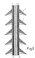
- FIG. 1 a longitudinal section through a composite insulator 1 is shown.
- a composite insulator 1 is the section of a long-rod insulator.
- a field control layer 3 is applied on a core 2 made of glass fiber reinforced plastic.
- it can have capacitive or resistive properties.
- it may contain ZnO microvaristors for resistive field control.
- the field control layer 3 is covered by a protective layer 4, which consists of an erosion and Kriechstromfesten material and the field control layer 3 protects against weathering and pollution.
- the screens 5 are arranged at regular intervals, which are injected from one of the known polymeric plastics.
- the field control layer 3 in a partial region of the insulator 1 consists of two layers 31 and 32, of which the layer 32 is arranged above the continuous layer 31.
- the two layers 31 and 32 may have different field control properties. So can the outer Layer 32 capacitive and the continuous layer 31 have resistive properties. Such an arrangement of the layers may be advantageous, for example, in the field of fittings in terms of constructive field disturbances.
- the field control layer 3 is uniformly thick throughout. In the area where the field control layer 3 is double-layered, by reducing the extrusion, the inner layer 31 can be thinned.
- the outer layer 32 can be applied so thick that a uniform, uniform layer thickness is achieved.
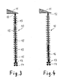
- FIGS. 3 and 4 show long-rod insulators 10, as used for example in high-voltage overhead lines.
- the structure of the field control layers of these insulators may for example correspond to the structure as in the in the FIGS. 1 or 2 is described insulators described.
- the insulators 10 each depend on a traverse 11 of a high-voltage mast, not shown here.
- the attachment takes place in a known manner with a fitting 12 made of metal.
- the conductor cables 14 are fastened by means of a further armature 13.
- the isolators 10 which are 4 meters in length, are only partially cut-off, as in FIG FIG. 3 represented, or only in a certain area on a fitting, as in FIG. 4 shown coated with a field control layer.
- the insulator 10 in FIG. 3 each has five equal areas 15 in which the core is covered with a field control layer. They are each interrupted by areas of equal size without field control layer.
- the insulator 10 in FIG. 4 has a portion 16 which is covered with a field control layer and which extends from the armature 13, to which the conductors 14 are attached, upwards over one third of the rod length.
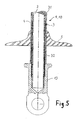
- FIG. 5 shows a schematic representation of a transition region from a fitting to the shield shell area in longitudinal section. It is a section through the end of an insulator with a fitting to which the conductors are attached, as in the Figures 3 or 4 is shown. Matching features with the Figures 2 . 3 and 4 are designated by the same reference numerals.
- the core consists of a rod 2 made of glass fiber reinforced plastic, which is coated with a field control layer 3, the in turn is enveloped by a protective layer 4. On this protective layer, the umbrellas 5 are raised.
- the field control layer 3 corresponds in structure to that as shown in FIG FIG. 2 is shown.
- the end of the rod 2 is enclosed by the fitting 13.
- a layer 31 completely covers the core 2 of the insulator on the length visible in the illustration. It is a layer with resistive effect and contains microvaristors.
- the capacitive field control is particularly suitable to reduce field strength peaks that are constructive, for example, by edges or stepped transitions, as they occur at the transition from a fitting to the insulator.
- To improve the conductive contact between the layers and the fitting of the core enclosing cavity of the fitting may be coated with a conductive paint. Also deposits of wire loops or wire nets are, as not shown, possible.
- FIG. 6 shows the result of a comparison test between a long-rod insulator whose surface corresponds to a field control layer FIG. 1 coated and a conventional long-rod insulator as reference insulator, which was equipped exclusively with HTV silicone without field control layer.
- the umbrellas were each made of HTV silicone. The striking distance was 2765 mm.
- a 3 mm thick polymer layer cross-sectional area: 1.8 cm 2 was applied to a GRP rod with a diameter of 16 mm.
- the polymer layer for field control were microvaristors, ZnO varistors in powder form, in a proportion of 50 to 90% by weight, preferably 70% by weight with a particle size of 10 nm to 100 ⁇ m, preferably between 0, 1 [mu] m and 10 [mu] m have been added.
- the filling level of the microvaristors was above the percolation limit, ie the microvaristors were in direct electrical contact with each other.
- FIG. 6 On the left are the isolator with field control layer and on the right the reference insulator during the comparison test. With an applied AC voltage of 750 kV (effective), the insulators were irrigated. While the reference insulator under the bottom five, the conductor side facing screens shows strong discharge activities, the equipped with the field control layer insulator is completely discharge-free.
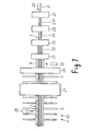
- Fig. 3 is a flow chart for explaining the manufacture of an insulator.
- the core 2 of the insulator to be produced is a rod which consists of a glass fiber reinforced plastic. This rod 2 is guided in the feed direction 20 by successively arranged stations, where it is completed to the insulator.
- a bonding agent 211 is applied so that the layers of the field control layer 3 to be subsequently applied are intimately joined to the core 2.
- a first layer 31 of the field control layer is applied, for example a layer with varistors, a layer with resistive character.
- another extruder 23 is provided for applying the further layer 32, for example a layer with a capacitive character.
- the next extruder 24 applies the protective layer 4.
- the insulator core can now be separated with a separating tool 25.
- the screens can be extruded or the already prefabricated umbrellas 5 are postponed.
- a thermal treatment 27 for curing the field control layer, the protective layer and the screens concludes the manufacture of the insulator 1; 10 off. After preparing the ends of the rod, the fittings can be attached to it.
Description
Die Erfindung betrifft einen feldgesteuerten Verbundisolator, enthaltend einen Stab oder Rohr als Isolatorkern aus faserverstärktem Kunststoff, der mit einer Schirmhülle überzogen und an seinen Enden mit Armaturen bestückt ist.The invention relates to a field-controlled composite insulator comprising a rod or tube as insulator core made of fiber-reinforced plastic, which is coated with a screen cover and equipped at its ends with fittings.
Die Werkstoffe eines Isolators werden durch die inhomogene Verteilung des elektrischen Feldes über seine Oberfläche stark belastet. Eine der Ursachen liegt in der konstruktiven Ausgestaltung eines Isolators. Insbesondere im Bereich der Armaturen verändert sich die Feldstärke wegen des Übergangs von den isolierenden Werkstoffen der Schirme und des Isolatorkerns zu einem metallischen Werkstoff, wegen des Übergangs zum Erdpotential an der Masttraverse beziehungsweise zum Leiterpotential, dort, wo die Leiterseile befestigt sind. Zur Verhinderung der dadurch bedingten örtlichen Feldstörung, insbesondere Feldstärkeüberhöhungen, kann die so genannte geometrische Feldsteuerung eingesetzt werden. Durch Abrundungen von Ecken und Kanten wird die Geometrie der Werkstücke, insbesondere die der Spannung führenden Teile, entschärft.The materials of an insulator are heavily loaded by the inhomogeneous distribution of the electric field across its surface. One of the causes lies in the structural design of an insulator. In particular, in the field of fittings, the field strength changes due to the transition from the insulating materials of the screens and the insulator core to a metallic material, because of the transition to ground potential at the mast crossbar or conductor potential, where the conductors are attached. To prevent the resulting local field disturbance, in particular field strength peaks, the so-called geometric field control can be used. By rounding corners and edges, the geometry of the workpieces, in particular the parts carrying the tension, is defused.
Eine weitere Ursache sind die Schmutzablagerungen, eine Belastung, die einen Isolator insgesamt betrifft. Auf Verbundisolatoren, die als Ausseninstallationen der Witterung ausgesetzt sind, lagern sich mit der Zeit dünne Schmutzschichten ab. Auf Grund der elektrischen Leitfähigkeit dieser Schichten können auf den Isolatoroberflächen Ladungsströme fliessen. Werden diese Schichten feucht, beispielsweise durch Regen oder Tau, wird die Leitfähigkeit noch weiter erhöht, was zu erhöhten Stromstärken der Leckund Entladungsströme und zu ohmschen Verlusten führt. Das bewirkt eine Erwärmung der Schmutzschichten mit der Folge ihrer Abtrocknung. Die abtrocknenden Schmutzschichten werden lokal hochohmig, so dass hier hohe Spannungsabfälle auftreten können. Wird dadurch bedingt die elektrische Durchschlagsfestigkeit der Umgebungsluft überschritten, treten Glimmentladungen oder elektrische Überschlagsentladungen auf, die die Ursache für eine Alterung und schliesslich Zerstörung des Werkstoffs der Isolatoroberfläche sind.Another cause is the dirt deposits, a burden that affects an insulator overall. On composite insulators, which are exposed as outdoor installations of the weather, deposited over time thin dirt layers. Due to the electrical conductivity of these layers, charge currents can flow on the insulator surfaces. If these layers become moist, for example due to rain or dew, the conductivity is increased even further, which leads to increased current strengths of the leakage and discharge currents and to ohmic losses. This causes a heating of the dirt layers with the result of their drying. The drying dirt layers become locally high-impedance, so that high voltage drops can occur here. If this causes the electrical dielectric strength of the ambient air to be exceeded, glow discharges or electrical flashover discharges occur, which are the cause of aging and finally destruction of the material of the insulator surface.
Als Massnahmen zur Vergleichmässigung des elektrischen Feldes und zur Vermeidung örtlicher Feldstörung, insbesondere Feldstärkeüberhöhungen, werden örtliche Überzüge oder Beschichtungen aus Isolierwerkstoffen, beispielsweise Kunststoffen wie Epoxidharze und Polymere, mit Einlagerungen aus dielektrischen oder/und ferroelektrischen Stoffen als Feldsteuerschichten aufgebracht.As measures to equalize the electric field and to avoid local field disturbance, in particular field strength peaks, local coatings or coatings of insulating materials, such as plastics such as epoxy resins and polymers are applied with deposits of dielectric and / or ferroelectric materials as field control layers.
Von einem Ausführungsbeispiel des Hochspannungs-Verbundisolators gemäss der
Aus der
Weiter wird in der
Es ist die Aufgabe der vorliegenden Erfindung einen Verbundisolator vorzustellen, bei dem die Ursachen zur Bildung von örtlichen Feldstörungen, insbesondere Feldstärkeüberhöhungen und Coronaentladungen, durch eine auf die jeweilige Störung abgestimmte Feldsteuerschicht weitestgehend beseitigt sind.It is the object of the present invention to present a composite insulator in which the causes for the formation of local field disturbances, in particular field strength peaks and corona discharges, are largely eliminated by a field control layer tuned to the respective disturbance.
Die Lösung der Aufgabe erfolgt konstruktiv mit Hilfe der kennzeichnenden Merkmale des erfindungsgemäßen Isolators nach Anspruch 1 und mittels eines Verfahrens nach Anspruch 15 zu dessen Herstellung. Vorteilhafte Ausgestaltungen des Isolators und der Verfahren zu seiner Herstellung werden in den abhängigen Ansprüchen beansprucht.The object is achieved constructively with the help of the characterizing features of the insulator according to the invention according to
Die Feldsteuerschicht des erfindungsgemäßen Verbundisolators umfasst demnach eine Lage, worin der Anteil der das elektrische Feld beeinflussenden Partikel über die Länge der Lage unterschiedlich ist.The field control layer of the composite insulator according to the invention accordingly comprises a layer in which the proportion of the particles influencing the electric field is different over the length of the layer.
Der galvanische Kontakt zwischen der Feldsteuerschicht und der Armatur kann beispielsweise durch Leitlack, Metallringe oder Drahtgewebe hergestellt werden. Ausserhalb der Armatur wird die Feldsteuerschicht von einer Schutzschicht oder direkt von den nahtlos auf den Kern extrudierten Schirmen umgeben. Der Isolatorkern als Rohr oder Stab besteht in der Regel aus einem mit Glasfasern verstärkten Duromer wie beispielsweise Epoxidharz oder Polyesterharz.The galvanic contact between the field control layer and the fitting can be produced for example by conductive ink, metal rings or wire mesh. Outside the valve, the field control layer is surrounded by a protective layer or directly by the screens extruded seamlessly on the core. The insulator core as a pipe or rod is usually made of a fiberglass-reinforced thermoset such as epoxy or polyester resin.
Die Erfindung eignet sich für alle Arten von Verbundisolatoren, insbesondere für Hängeisolatoren, Stützisolatoren oder Durchführungsisolatoren. Der Einsatzbereich beginnt bei Hochspannungen über 1 kV und ist besonders effektiv bei Spannungen über 72,5 kV.The invention is suitable for all types of composite insulators, in particular for suspension insulators, post insulators or bushing insulators. The field of application starts at high voltages above 1 kV and is particularly effective at voltages above 72.5 kV.
Die Feldsteuerschicht besteht in der Regel aus demselben Werkstoff wie die sie überdeckende Schutzschicht. Die Schutzschicht kann aber auch vorteilhaft aus einem höheren erosionsund kriechstromfesten Werkstoff bestehen. Die Schutzschicht besteht in jedem Fall aus einem Werkstoff mit hohen Isolationseigenschaften. Werkstoffe mit diesen Eigenschaften sind elastomere Werkstoffe, beispielsweise polymere Kunststoffe wie Silikonkautschuk (HTV) der Härteklassen Shore A 60 bis 90 oder Ethylen-Propylen-Copolymer (EPM). Auf den so vorbereiteten Kern mit Feldsteuerschicht und Schutzschicht werden die Schirme aufgeschoben, die aus demselben Werkstoff wie Schutzschicht bestehen können. Die Schutzschicht und die Schirme können auch in ein und demselben Arbeitsgang aus demselben Werkstoff auf den Kern extrudiert werden, wie es aus dem Patent
Die Feldsteuerung kann resistiv oder kapazitiv oder in einer Kombination miteinander erfolgen. Dazu wird der Werkstoff der Feldsteuerschicht mit Partikeln als Füllstoff gefüllt, die die Feldsteuerung bewirken.The field control can be resistive or capacitive or in combination with each other. For this purpose, the material of the field control layer is filled with particles as filler, which cause the field control.
Zur resistiven Feldsteuerung, auch ohmschen Feldsteuerung genannt, ist eine Feldsteuerschicht mit ohmschen leitenden (conductiven) oder/und halbleitenden (semiconductiven) Füllstoffen vorgesehen. Bei den ohmschen leitenden Füllstoffen wird die lineare Werkstoffabhängigkeit zwischen Spannung und Strom ausgenutzt. Zu den leitfähigen Füllstoffen gehören beispielsweise Russ, Fe3O4 und andere Metalloxide.For resistive field control, also called ohmic field control, a field control layer with ohmic conductive (conductive) and / or semiconducting (semiconductive) fillers is provided. In the ohmic conductive fillers, the linear material dependence between voltage and current is utilized. The conductive fillers include, for example, carbon black, Fe 3
Es gibt halbleitende Werkstoffe mit einer nicht-linearen Abhängigkeit zwischen Spannung und Strom. Diese Eigenschaften haben Varistoren, beispielsweise ZnO, die ab einer definierten Spannung beziehungsweise Feldstärke leitfähig werden und damit die Fähigkeit besitzen, Überspannungen zu begrenzen. Für die resistive Feldsteuerung eignen sich insbesondere Mikrovaristoren. Das sind Varistoren in Pulverform mit Korndurchmessern zwischen 50 nm und 100 [mu]m. Bei geeigneter Auslegung kann erreicht werden, dass ein mit Mikrovaristoren gefüllter Werkstoff, insbesondere ein Silikonwerkstoff, bei Stossspannungsbeanspruchung eine hohe elektrische Leitfähigkeit und einen niedrigen Verlustleistungsumsatz im Dauerbetrieb aufweist.There are semiconducting materials with a non-linear dependence between voltage and current. These properties have varistors, for example ZnO, which become conductive above a defined voltage or field strength and thus have the ability to limit overvoltages. Microvaristors are particularly suitable for resistive field control. These are varistors in powder form with grain diameters between 50 nm and 100 μm. With a suitable design, it can be achieved that a material filled with microvaristors, in particular a silicone material, exhibits high electrical conductivity and low power dissipation in continuous operation under surge stress.
Bei der kapazitiven Feldsteuerung werden Werkstoffe mit dielektrischen Eigenschaften eingesetzt wie beispielsweise TiO2, BaTi03 oder TiOx. Diese Werkstoffe haben eine hohe Dielektrizitätskonstante (Permittivität).Capacitive field control uses materials with dielectric properties such as TiO2, BaTi03 or TiOx. These materials have a high dielectric constant (permittivity).
Die refraktive Feldsteuerung ist eine Sonderform der kapazitiven Feldsteuerung. Durch geeignete Anordnung von Werkstoffen mit unterschiedlich grossen Dielektrizitätskonstanten werden an den Übergängen der Werkstoffe die Feldlinien so gebrochen, dass örtliche Feldstörungen, insbesondere Feldstärkeüberhöhungen, möglichst beseitigt werden. Die Feldsteuerschicht kann aus einer Lage oder mehreren Lagen bestehen, wobei die einzelnen Lagen unterschiedliche Feldsteuereigenschaften haben können.Refractive field control is a special form of capacitive field control. By suitable arrangement of materials with different dielectric constants, the field lines at the transitions of the materials are so broken that local field disturbances, in particular field strength peaks, are eliminated as far as possible. The field control layer may consist of one layer or multiple layers, wherein the individual layers may have different field control properties.
Die Partikel, die als Füllstoffe den Lagen der Feldsteuerschicht zugegeben werden, haben einen Durchmesser von 10 nm bis zu 100 [mu]m, vorzugsweise in einem Bereich von 0,1 [mu]m bis 10 [mu]m. Ihre Grösse richtet sich nach der Dicke der Lage und der Intensität und der Ausdehnung der zu erwartenden Feldstörung.The particles added as fillers to the layers of the field control layer have a diameter of 10 nm to 100 μm, preferably in a range of 0.1 μm to 10 μm. Their size depends on the thickness of the layer and the intensity and extent of the expected field disturbance.
Der Anteil der Partikel liegt zwischen 50 und 90 % Gewichtsprozent, vorteilhaft bei 70 %.The proportion of particles is between 50 and 90% by weight, preferably 70%.
Der Anteil der Partikel, der Füllgrad, kann oberhalb der Perkolationsgrenze liegen, d.h. dass sich die Partikel in direktem elektrischem Kontakt befinden.The proportion of particles, the degree of filling, may be above the percolation limit, i. that the particles are in direct electrical contact.
Die Dicke einer Lage einer Feldsteuerschicht kann 1 mm bis 5 mm betragen, in der Regel 2 mm bis 3 mm. Sie richtet sich nach der Intensität und der Ausdehnung der zu erwartenden Feldstörung.The thickness of a layer of a field control layer may be 1 mm to 5 mm, usually 2 mm to 3 mm. It depends on the intensity and extent of the expected field disturbance.
Die Feldsteuerschicht kann aus einer Lage bestehen und ausschliesslich resistive Partikel als Füllstoff enthalten. Eine solche Schicht ist an den Stellen des Isolators vorgesehen, an denen vorzugsweise eine resistive, eine ohmsche Feldsteuerung erforderlich ist.The field control layer can consist of one layer and contain only resistive particles as filler. Such a layer is provided at the locations of the insulator to which preferably a resistive, an ohmic field control is required.
Die Feldsteuerschicht kann aus einer Lage bestehen und ausschliesslich kapazitive Partikel als Füllstoff enthalten. Eine solche Schicht ist an den Stellen des Isolators vorgesehen, an denen vorzugsweise eine kapazitive, oder speziell eine refraktive, Feldsteuerung erforderlich ist.The field control layer can consist of one layer and contain only capacitive particles as filler. Such a layer is provided at the locations of the insulator to which preferably a capacitive, or in particular a refractive, field control is required.
Die Feldsteuerschicht kann aus einer Lage bestehen und der Anteil der resistiven oder kapazitiven Partikel kann über die Länge der Lage unterschiedlich sein. Bei gleicher Dicke kann durch Änderung des Anteils an Füllstoffen in der Lage die Intensität der Einwirkung auf die Feldstörungen örtlich verändert werden. Die Änderung des Anteils am Füllstoff ist dann möglich, wenn der Füllstoff nicht bereits dem Werkstoff der Lage vor dem Auftragen zugemischt wurde, sondern erst in oder vor der Düse zum Auftragen der Lage dem Werkstoff zugemischt wird.The field control layer may consist of one layer and the proportion of the resistive or capacitive particles may be different over the length of the layer. With the same thickness, the intensity of the effect on the field disturbances can be changed locally by changing the proportion of fillers in the position. The change in the proportion of the filler is possible if the filler has not already been added to the material of the layer before application, but only in or before the nozzle for applying the layer is mixed with the material.
Die Dicke einer Lage einer Feldsteuerschicht kann über ihre Länge wechseln. Möglich ist das durch die Änderung der Vorschubgeschwindigkeit innerhalb des Extruders, der die Lage auf den Kern aufträgt.The thickness of a layer of a field control layer can change over its length. This is possible by changing the feed rate within the extruder, which applies the layer to the core.
Die Feldsteuerschicht kann auch aus mindestens zwei Lagen mit resistiven oder kapazitiven Partikeln als Füllstoffen bestehen. Dabei kann die eine Lage einen höheren Anteil an resistiven beziehungsweise kapazitiven Partikeln haben als die andere Lage.The field control layer can also consist of at least two layers with resistive or capacitive particles as fillers. The one layer may have a higher proportion of resistive or capacitive particles than the other layer.
Die Feldsteuerschicht kann auch aus mindestens zwei Lagen bestehen, wobei eine Lage ausschliesslich resistive und eine andere Lage ausschliesslich kapazitive Partikel enthält. Bei mehreren Lagen übereinander können sich die Lagen in ihrer Reihenfolge abwechseln.The field control layer may also consist of at least two layers, one layer containing exclusively resistive and another layer exclusively capacitive particles. For several layers one above the other, the layers may alternate in their order.
Die Feldsteuerschicht kann aus einer Lage bestehen und eine Mischung von resistiven und kapazitiven Partikeln enthalten.The field control layer may consist of one layer and contain a mixture of resistive and capacitive particles.
Die Feldsteuerschicht kann auch aus mindestens zwei Lagen bestehen, wobei eine Lage eine Mischung von resistiven und kapazitiven Partikeln enthält und die andere Lage ausschliesslich resistive oder kapazitive Partikel enthält.The field control layer can also consist of at least two layers, one layer containing a mixture of resistive and capacitive particles and the other layer containing only resistive or capacitive particles.
Bei mehreren Lagen übereinander können sich die Lagen hinsichtlich ihrer Wirkung auf das elektrische Feld in ihrer Reihenfolge oder/und Zusammensetzung abwechseln. Ausserdem kann der Anteil der kapazitven oder/und resistiven Partikeln in den einzelnen Lagen der Schicht unterschiedlich sein.In the case of several layers one above the other, the layers may alternate in their order or composition in terms of their effect on the electric field. In addition, the proportion of capacitive and / or resistive particles in the individual layers of the layer may be different.
Die Feldsteuerschicht kann über die gesamte Länge des Isolatorkerns aufgetragen sein. Sie kann sich aber auch nur über Teilbereiche erstrecken, wie beispielsweise im Bereich der Armaturen. Die Feldsteuerschicht kann auch in einzelne Abschnitte unterteilt und dadurch unterbrochen sein.The field control layer can be applied over the entire length of the insulator core. However, it can also extend only over partial areas, such as in the field of fittings. The field control layer can also be divided into individual sections and thereby interrupted.
In dem Fall, in dem die Feldsteuerschicht in einzelne Abschnitte unterteilt ist und aus mindestens zwei Lagen besteht, kann im Grenzbereich zum schichtfreien Abschnitt eine Lage länger sein als die andere und über die darüber oder darunter befindliche Lage hinaus weiter bis zu dem schichtfreien Abschnitt reichen, so dass der das Feld beeinflussende Charakter dieser Lage ausschliesslich zur Wirkung kommt.In the case where the field control layer is divided into individual sections and consists of at least two layers, one layer may be longer than the other bordering the layerless section and extending beyond the layer above or below to the layerless section, so that the field influencing character of this situation comes exclusively to effect.
Durch die zuvor beschriebenen diskontinuierlichen Anordnungen der Schicht können hohe Verlustleistungen vermieden werden.By the above-described discontinuous arrangements of the layer high power losses can be avoided.
Gegebenenfalls können die einzelnen Lagen einer Feldsteuerschicht durch isolierende Zwischenlagen voneinander getrennt sein, wenn Unterschiede der Leitfähigkeit im Kontaktbereich der beiden Lagen selbst zu unerwünschten Veränderungen des Feldes führen könnten.Optionally, the individual layers of a field control layer can be separated from one another by insulating intermediate layers if differences in the conductivity in the contact region of the two layers themselves could lead to undesired changes in the field.
Die oben aufgeführten Kombinationsmöglichkeiten der Anzahl der Lagen, der Anordnung der einzelnen Lagen innerhalb einer Schicht und der Grad der Füllung mit kapazitven oder/und resistiven Partikeln erlaubt es, an den möglichen Stellen, wo eine für den Isolator schädliche Inhomogenität des elektrischen Feldes auftreten kann, diese durch eine darauf abgestimmte Schicht zu verhindern oder zu unterdrücken.The above-mentioned possible combinations of the number of layers, the arrangement of the individual layers within a layer and the degree of filling with capacitive and / or resistive particles makes it possible to occur at the possible locations where a harmonic inhomogeneity of the electric field can occur. to prevent or suppress them by means of a coordinated layer.
Für die resistive Feldsteuerung werden Mikrovaristoren bevorzugt, insbesondere aus ZnO.For resistive field control, microvaristors are preferred, in particular ZnO.
Zum Schutz der Feldsteuerschicht kann diese mit einer Schutzschicht, beispielsweise einer isolierenden HTV-Silikon-Extrudatschicht mit extrem guten Kriechstrom-, Erosionsund Witterungsbeständigkeiten, überzogen sein, auf die dann die Schirme geschoben werden. Diese Schutzschicht erhöht die Freiluftbeständigkeit und kann bis zu 5 mm dick sein, vorteilhaft zwischen 2 mm und 3 mm.To protect the field control layer, it can be coated with a protective layer, for example an insulating HTV silicone extrudate layer with extremely good tracking, erosion and weathering resistance, onto which the screens are then pushed. This protective layer increases the outdoor resistance and can be up to 5 mm thick, advantageously between 2 mm and 3 mm.
Auf den Kern mit der Feldsteuerschicht können aber auch die Schirme direkt lückenlos aufextrudiert werden, wie es aus dem Patent
Die Feldsteuerschicht kann auf den Kern durch einen Extruder aufgebracht werden, durch den der Kern hindurchgeschoben wird. Soll eine Schicht mit mehreren Lagen auf dem Kern aufgetragen werden, so kann das durch eine mehrstufige Düse oder durch mehrere hintereinander angeordnete Extruder erfolgen. Das Auftragen der Lagen muss so erfolgen, dass sie gut am Isolatorkern haften und sich miteinander zu einer Schicht verbinden. Gegebenenfalls ist das Auftragen von Haftverrnittiern erforderlich.The field control layer can be applied to the core by an extruder through which the core is pushed. If a layer with several layers is to be applied to the core, this can be done by a multi-stage nozzle or by several extruders arranged one behind the other. The application of the layers must be such that they adhere well to the insulator core and join together to form a layer. If necessary, the application of Haftverrnittiern required.
Die Erfindung bietet die Möglichkeit, eine Feldsteuerschicht nur an den Stellen einzusetzen, an denen kritische Störungen des elektrischen Feldes, insbesondere Feldstärkeüberhöhungen, auftreten können. Dadurch können die Verlustleistungen an den Isolatoren auf Minimalwerte reduziert werden.The invention offers the possibility of using a field control layer only at those points where critical disturbances of the electric field, in particular field strength peaks, can occur. As a result, the power losses at the insulators can be reduced to minimum values.
Die Zusammensetzung der Feldsteuerschicht aus Lagen mit resistiven oder/und kapazitiven Partikeln oder der Aufbau der Schicht aus zwei oder mehreren Lagen, insbesondere mit unterschiedlichen Partikeln oder/und Partikelanteilen, sowie die Variation der Überdeckungslängen der Lagen können vorteilhaft auf die zu beseitigenden Feldstörungen, insbesondere Feldstärkeüberhöhungen, besonders durch lokale Verschmutzungen hervorgerufen, abgestimmt werden. Die Feldverteilung entlang des Isolators wird dadurch vergleichmässigt. Dadurch wird die Entstehung von Glimmentladungen, Koronaentladungen und Überschlägen vermieden, wodurch eine vorzeitige Alterung des Werkstoffs vermieden wird.The composition of the field control layer of layers with resistive and / or capacitive particles or the structure of the layer of two or more layers, in particular with different particles and / or particle proportions, as well as the variation of the overlap lengths of the layers can advantageously on the field disturbances to be eliminated, in particular field strength peaks , especially caused by local pollution. The field distribution along the insulator is thereby made uniform. This avoids the formation of corona discharges, corona discharges and flashovers, which prevents premature aging of the material.
An Hand von Beispielen wird die Erfindung näher erläutert. Es zeigen:
- Fig. 1
- einen Ausschnitt aus einem Verbundisolator mit einer Feldsteuerschicht, aus einer Lage bestehend, im Längsschnitt,
- Fig. 2
- einen Ausschnitt aus einem Verbundisolator mit einer Feldsteuerschicht aus zwei Lagen, wobei eine Lage nur einen Teil des Kerns überdeckt,
- Fig. 3
- einen Langstabisolator, bei dem die Bereiche gekennzeichnet sind, in denen eine Feldsteuerschicht aufgetragen ist,
- Fig. 4
- einen Langstabisolator, bei dem eine Feldsteuerschicht im Bereich der Armatur aufgetragen ist, an der die Leiterseile befestigt sind,
Fig. 5 den Übergangsbereich von einem Isolatorkern zu einer Armatur im Längsschnitt, - Fig. 6
- einen Vergleichstest zwischen einem Isolator mit Feldsteuerschicht und einem herkömmlichen Isolator bei anliegender Wechselspannung unter Beregnung und
- Fig. 7
- ein Ablaufdiagramm zur Erläuterung der Herstellung eines Isolators.
- Fig. 1
- a section of a composite insulator with a field control layer, consisting of a layer, in longitudinal section,
- Fig. 2
- a section of a composite insulator with a field control layer of two layers, wherein a layer covers only a part of the core,
- Fig. 3
- a long-rod insulator, in which the areas are marked in which a field control layer is applied,
- Fig. 4
- a long-rod insulator in which a field control layer is applied in the region of the armature to which the conductor cables are attached,
Fig. 5 the transition region from an insulator core to a valve in longitudinal section, - Fig. 6
- a comparison test between an insulator with field control layer and a conventional insulator with applied AC voltage under irrigation and
- Fig. 7
- a flowchart for explaining the production of an insulator.
In
In
Die
Bei dem Isolator 1 oder 10 besteht der Kern aus einem Stab 2 aus glasfaserverstärktem Kunststoff, der mit einer Feldsteuerschicht 3 überzogen ist, die wiederum von einer Schutzschicht 4 umhüllt ist. Auf dieser Schutzschicht sind die Schirme 5 aufgezogen. Die Feldsteuerschicht 3 entspricht in ihrem Aufbau der, wie sie in
In
In
Je nach Herstellungsverfahren der Schirmhülle kann jetzt der Isolatorkern mit einem Trennwerkzeug 25 getrennt werden. Im nächsten Schritt 26 können die Schirme aufextrudiert oder die bereits vorgefertigten Schirme 5 aufgeschoben werden. Eine thermische Behandlung 27 zur Aushärtung der Feldsteuerschicht, der Schutzschicht und der Schirme schliesst die Herstellung des Isolators 1 ; 10 ab. Nach Vorbereitung der Enden des Stabs können die Armaturen darauf befestigt werden.Depending on the manufacturing process of the screen cover, the insulator core can now be separated with a separating
Werden die Schutzschicht und die Schirmhülle in ein und demselben Arbeitsgang als eine gemeinsame Schicht auf den Isolatorkern 2 aufgebracht, erfolgt die Herstellung in der Station 26, entsprechend dem Patent
Claims (19)
- Composite insulator (1, 10) containing a core (2) and a protective layer (4) which surrounds the core (2), wherein a field control layer (3) which contains particles, as a filler, which influence the electrical field of the insulator, is arranged between the core (2) and the protective layer (4) in at least one section (15, 16) of the insulator (1, 10),
characterized in that
the field control layer (3) has a stratum (31, 32) wherein the proportion of the particles which influence the electrical field differs over the length of the stratum (31, 32). - Composite insulator (1, 10) according to Claim 1,
characterized in that
the field control layer (3) consists of one, two or more strata (31, 32), and in that the individual strata (31, 32) have different field control characteristics. - Composite insulator (1, 10) according to Claim 1 or 2,
characterized in that
the field control layer (3) consists of one stratum (31, 32) and contains exclusively resistive or capacitive particles as a filler. - Composite insulator (1, 10) according to one of Claims 1 or 2,
characterized in that
the field control layer (3) consists of at least two strata (31, 32), and in that one of the strata (31, 32) has a higher proportion of resistive or capacitive particles than the other. - Composite insulator (1, 10) according to one of Claims 1 or 2,
characterized in that
the field control layer (3) consists of at least two strata (31, 32), and in that one of the strata (31) contains exclusively resistive particles, and the other stratum (32) contains exclusively capacitive particles. - Composite insulator (1, 10) according to one of Claims 1 or 2,
characterized in that
the field control layer (3) consists of one stratum (31, 32) and contains a mixture of resistive and capacitive particles. - Composite insulator (1, 10) according to one of Claims 1 or 2,
characterized in that
the field control layer (3) consists of at least two strata (31, 32), and in that one stratum (31, 32) contains a mixture of resistive or capacitive particles, and the other stratum (31, 32) contains exclusively resistive or capacitive particles. - Composite insulator (1, 10) according to one of Claims 1 or 7,
characterized in that
the strata (31, 32) in a field control layer (3) when there are a plurality of strata (31, 32) one on top of the other alternate with respect to their effect on the electrical field, in their sequence and/or composition. - Composite insulator (1, 10) according to Claim 8,
characterized in that
the proportion of the capacitive and/or resistive particles in the individual strata (31, 32) of the layer (3) is different. - Composite insulator (1, 10) according to one of Claims 1 or 9,
characterized in that
the field control layer (3) is applied in individual sections (15) over the length of the core (2) of the insulator (10). - Composite insulator (1, 10) according to Claim 10,
characterized in that,
in the case of a field control layer (3) which is subdivided into individual sections and consists of at least two strata (31, 32), one stratum (31, 32) in the boundary area to the layer-free section is longer than the other and extends beyond the stratum (31, 32) located above or below it, to the layer-free section. - Composite insulator (1, 10) according to one of Claims 1 or 11,
characterized in that
the individual strata (31, 32) of the field control layer (3) are separated from one another by a stratum composed of an insulating material. - Composite insulator (1, 10) according to one of Claims 1 to 12,
characterized in that
the proportion of the particles in a layer is between 50 and 90 per cent by weight, preferably 70 per cent by weight. - Composite insulator (1, 10) according to Claim 13,
characterized in that
the proportion of the particles, the filling level, is above the percolation limit. - Method for producing a composite insulator (1, 10) containing a core (2) and a protective layer (4) which surrounds the core (2), according to one of Claims 1 to 14,
characterized in that
a field control layer (3) comprising at least one stratum (31, 32) of an elastomer material having a proportion of particles, which influence the electrical field of the insulator (1, 10), which proportion changes over the length of the layer, is applied to the core (2) of the insulator (1, 10) in at least one section (15, 16), and in that the entire core (2) is coated with the applied field control layer (3) with the protective layer (4), and in that the insulator (1, 10) is then subjected to heat treatment (27) in order to vulcanize the plastics. - Method according to Claim 15,
characterized in that
the field control layer (3) is applied in at least two strata (31, 32) with different effects on the electrical field. - Method according to Claim 15 or 16,
characterized in that
the field control layer (3) is applied in sections (15) to the core (2) of the insulator. - Method according to Claim 17,
characterized in that,
in the case of a field control layer (3) which is subdivided into individual sections and consists of at least two strata (31, 32), one stratum (31, 32) is applied in the boundary area to the layer-free section, beyond the stratum (31, 32) which is located above or below it, to the layer-free section. - Method according to one of Claims 15 to 18,
characterized in that
the particles which influence the electrical field of the insulator (1, 10) are added to the extrudate in a different amount, during the application of the stratum (31, 32) of the field control layer (3) to the core (2).
Priority Applications (2)
| Application Number | Priority Date | Filing Date | Title |
|---|---|---|---|
| SI200930550T SI2243145T1 (en) | 2008-02-14 | 2009-02-12 | Field-controlled composite insulator |
| PL09709505T PL2243145T3 (en) | 2008-02-14 | 2009-02-12 | Field-controlled composite insulator |
Applications Claiming Priority (2)
| Application Number | Priority Date | Filing Date | Title |
|---|---|---|---|
| DE102008009333A DE102008009333A1 (en) | 2008-02-14 | 2008-02-14 | Field-controlled composite insulator |
| PCT/EP2009/000983 WO2009100904A1 (en) | 2008-02-14 | 2009-02-12 | Field-controlled composite insulator |
Publications (2)
| Publication Number | Publication Date |
|---|---|
| EP2243145A1 EP2243145A1 (en) | 2010-10-27 |
| EP2243145B1 true EP2243145B1 (en) | 2013-01-23 |
Family
ID=40622154
Family Applications (1)
| Application Number | Title | Priority Date | Filing Date |
|---|---|---|---|
| EP09709505A Active EP2243145B1 (en) | 2008-02-14 | 2009-02-12 | Field-controlled composite insulator |
Country Status (9)
| Country | Link |
|---|---|
| US (1) | US8637769B2 (en) |
| EP (1) | EP2243145B1 (en) |
| JP (1) | JP5302978B2 (en) |
| CA (1) | CA2715651C (en) |
| DE (2) | DE102008009333A1 (en) |
| ES (1) | ES2401885T3 (en) |
| PL (1) | PL2243145T3 (en) |
| SI (1) | SI2243145T1 (en) |
| WO (1) | WO2009100904A1 (en) |
Families Citing this family (14)
| Publication number | Priority date | Publication date | Assignee | Title |
|---|---|---|---|---|
| JP5663085B2 (en) * | 2010-05-28 | 2015-02-04 | ラップ インシュレータース ゲゼルシャフト ミット ベシュレンクテルハフツング | Composite insulator |
| DE102010043990A1 (en) * | 2010-11-16 | 2012-05-16 | Siemens Aktiengesellschaft | Insulator arrangement and method for producing an insulator arrangement |
| DE102010043995A1 (en) * | 2010-11-16 | 2012-05-16 | Siemens Aktiengesellschaft | Insulator arrangement and method for producing an insulator arrangement |
| JP2012248525A (en) * | 2011-05-31 | 2012-12-13 | Tokyo Electric Power Co Inc:The | Polymer insulator |
| DE102011055401A1 (en) | 2011-11-16 | 2013-05-16 | Rwth Aachen | Funnel-shaped insulating body for isolating electric field producing conductor i.e. lead wire, of gas insulated direct current switchgear, has micro-hollow elements influencing field nonuniformly distributed in matrix material |
| DE102012104137A1 (en) * | 2012-05-11 | 2013-11-14 | Maschinenfabrik Reinhausen Gmbh | Field controlled composite insulator e.g. rod, has core, shielding sheath and field control layer that is applied by plasma coating to core, where dielectric properties are controlled by geometric structure of field-control layer |
| US9876342B2 (en) | 2013-09-25 | 2018-01-23 | 3M Innovative Properties Company | Compositions for electric field grading |
| FR3057697B1 (en) * | 2016-10-18 | 2020-02-14 | Sediver Sa | ISOLATOR FOR OVERHEAD POWER LINES WITH A PROTECTED LEAKAGE CURRENT |
| GB2578251B (en) * | 2017-07-13 | 2022-04-27 | Sumitomo Electric Industries | Non-ohmic composition and method for manufacturing same, cable interconnect unit and cable end-connect unit |
| CA2989069A1 (en) * | 2017-12-13 | 2019-06-13 | Hydro-Quebec | Composite, crosspiece coated with the composite and their use in an electric network |
| EP3591672B1 (en) | 2018-07-02 | 2023-03-29 | Hitachi Energy Switzerland AG | Insulator with resistivity gradient |
| CN109786047A (en) * | 2018-12-29 | 2019-05-21 | 江苏神马电力股份有限公司 | Hollow combined insulator and breaker |
| EP3813082B1 (en) * | 2019-10-21 | 2023-07-19 | Hitachi Energy Switzerland AG | Insulator shed having non-circular tip |
| DE102022206149A1 (en) | 2022-06-21 | 2023-12-21 | Siemens Energy Global GmbH & Co. KG | Bushing insulator |
Family Cites Families (16)
| Publication number | Priority date | Publication date | Assignee | Title |
|---|---|---|---|---|
| DE1465287B2 (en) | 1964-05-14 | 1973-05-03 | Brown, Boveri & Cie Ag, 6800 Mannheim | HIGH VOLTAGE COMPOSITE INSULATOR |
| DE1515467B2 (en) * | 1965-04-01 | 1971-04-15 | Brown, Boven & Cie AG, 6800 Mann heim | HIGH VOLTAGE COMPOSITE INSULATOR |
| DE2006247A1 (en) | 1970-02-12 | 1971-10-07 | Jenaer Glaswerk Schott & Gen | High voltage insulator |
| DD139962A3 (en) | 1978-04-18 | 1980-01-30 | Manfred Kahle | METHOD FOR PRODUCING A PLASTIC INSULATOR |
| DE3214141A1 (en) | 1982-04-14 | 1983-10-20 | Interpace Corp., Parsippany, N.J. | Polymer rod insulator with improved interference-field and corona characteristics |
| NO167618C (en) * | 1989-03-20 | 1991-11-20 | Alcatel Stk As | SURVIVAL DEVICE FOR ELECTRICAL APPLIANCES. |
| JP3602634B2 (en) | 1996-01-09 | 2004-12-15 | 日本碍子株式会社 | Semiconductive composite insulator |
| SE510819C2 (en) * | 1997-02-14 | 1999-06-28 | Ifoe Ceramics Ab | Electric high voltage insulator with a semiconducting surface layer |
| DE19856123C2 (en) | 1998-12-04 | 2000-12-07 | Siemens Ag | Hollow insulator |
| DE19858215C2 (en) | 1998-12-17 | 2003-07-24 | Ceramtec Ag | Method and device for producing composite insulators |
| GB0103255D0 (en) * | 2001-02-09 | 2001-03-28 | Tyco Electronics Raychem Gmbh | Insulator arrangement |
| EP1337022A1 (en) * | 2002-02-18 | 2003-08-20 | ABB Schweiz AG | Surrounding body for a high voltage cable and cable element, which is provided with such a surrounding body |
| EP1577904B1 (en) * | 2004-03-15 | 2012-02-22 | ABB Research Ltd. | High voltage bushing with element for electric-field control |
| DE102005041167A1 (en) * | 2005-08-30 | 2007-03-01 | Obo Bettermann Gmbh & Co. Kg | Lightning rod conductor has conductor embedded in particle filled polymer as isolator with outer covering of electrical non linear material |
| EP1870975B1 (en) * | 2006-06-21 | 2010-08-04 | ABB Technology Ltd | A device for electric field control |
| EP1936638A1 (en) * | 2006-12-18 | 2008-06-25 | Abb Research Ltd. | An electric insulator and use thereof |
-
2008
- 2008-02-14 DE DE102008009333A patent/DE102008009333A1/en not_active Withdrawn
-
2009
- 2009-02-12 EP EP09709505A patent/EP2243145B1/en active Active
- 2009-02-12 DE DE202009018686U patent/DE202009018686U1/en not_active Expired - Lifetime
- 2009-02-12 SI SI200930550T patent/SI2243145T1/en unknown
- 2009-02-12 ES ES09709505T patent/ES2401885T3/en active Active
- 2009-02-12 WO PCT/EP2009/000983 patent/WO2009100904A1/en active Application Filing
- 2009-02-12 JP JP2010546261A patent/JP5302978B2/en active Active
- 2009-02-12 PL PL09709505T patent/PL2243145T3/en unknown
- 2009-02-12 CA CA2715651A patent/CA2715651C/en active Active
-
2010
- 2010-08-16 US US12/856,806 patent/US8637769B2/en active Active
Also Published As
| Publication number | Publication date |
|---|---|
| ES2401885T3 (en) | 2013-04-25 |
| DE202009018686U1 (en) | 2012-11-06 |
| EP2243145A1 (en) | 2010-10-27 |
| US8637769B2 (en) | 2014-01-28 |
| CA2715651C (en) | 2016-05-24 |
| JP2011514626A (en) | 2011-05-06 |
| DE102008009333A1 (en) | 2009-08-20 |
| SI2243145T1 (en) | 2013-05-31 |
| PL2243145T3 (en) | 2013-06-28 |
| CA2715651A1 (en) | 2009-08-20 |
| US20110017488A1 (en) | 2011-01-27 |
| JP5302978B2 (en) | 2013-10-02 |
| WO2009100904A1 (en) | 2009-08-20 |
Similar Documents
| Publication | Publication Date | Title |
|---|---|---|
| EP2243145B1 (en) | Field-controlled composite insulator | |
| EP1476928B1 (en) | Sleeve for a high-voltage cable and cable element provided with a sleeve of this type | |
| EP0416452B1 (en) | Electro-filter cable | |
| EP1577904A1 (en) | High voltage bushing with element for electric-field control | |
| DE2746870A1 (en) | METHOD FOR PRODUCING OUTDOOR COMPOSITE INSULATORS | |
| DE2436413A1 (en) | HIGH VOLTAGE CABLE | |
| AT518664B1 (en) | HVDC air choke coil and method of manufacture | |
| EP1760855A1 (en) | Lightning current conducting device | |
| EP2577685B1 (en) | Composite insulator | |
| EP0068067B1 (en) | High voltage resistor for open air insulating arrangements | |
| DE1765602B1 (en) | Abrasion-resistant electrical cable with a smooth surface | |
| EP2715743A1 (en) | Electric component for a high-voltage system | |
| CH715655B1 (en) | Grommet with a self-adaptively regulating electrical conductivity composite material. | |
| DE102006056563B4 (en) | Spacer for ensuring the separation distance for partially insulated lightning protection systems | |
| DE602005005694T2 (en) | HIGH OR MEDIUM VOLTAGE DEVICE WITH PARTICULAR DIELECTRIC SYSTEM | |
| EP3410451B1 (en) | Shield ring for a transformer coil | |
| DE102017217163B4 (en) | Electrical equipment and manufacturing process for electrical equipment | |
| WO2020030753A1 (en) | Material for controlling an electric field according to the direction | |
| EP0779692A1 (en) | Process for earthing a screen of an electrical cable and electrical cable | |
| DE102017212026A1 (en) | Shield ring and / or pitch compensation for a transformer coil | |
| DE3214141A1 (en) | Polymer rod insulator with improved interference-field and corona characteristics | |
| DE102012000125A1 (en) | Device for improving the electrical properties of a coating of a conductor or the like by insulating materials, and a method for using such a device | |
| CH170845A (en) | Process for the manufacture of products with mutually insulated electrical conductors and insulated conductors manufactured according to this process. | |
| DE1538405A1 (en) | Surge arresters | |
| DE1957460B2 (en) | High voltage composite insulator for overhead lines and switchgear - with fibre reinforced resin tension rod core and insulating shields |
Legal Events
| Date | Code | Title | Description |
|---|---|---|---|
| PUAI | Public reference made under article 153(3) epc to a published international application that has entered the european phase |
Free format text: ORIGINAL CODE: 0009012 |
|
| 17P | Request for examination filed |
Effective date: 20100908 |
|
| AK | Designated contracting states |
Kind code of ref document: A1 Designated state(s): AT BE BG CH CY CZ DE DK EE ES FI FR GB GR HR HU IE IS IT LI LT LU LV MC MK MT NL NO PL PT RO SE SI SK TR |
|
| AX | Request for extension of the european patent |
Extension state: AL BA RS |
|
| RIN1 | Information on inventor provided before grant (corrected) |
Inventor name: SEIFERT, JENS Inventor name: HINRICHSEN, VOLKER Inventor name: DENNDOERFER, HEINZ |
|
| DAX | Request for extension of the european patent (deleted) | ||
| GRAP | Despatch of communication of intention to grant a patent |
Free format text: ORIGINAL CODE: EPIDOSNIGR1 |
|
| GRAS | Grant fee paid |
Free format text: ORIGINAL CODE: EPIDOSNIGR3 |
|
| GRAA | (expected) grant |
Free format text: ORIGINAL CODE: 0009210 |
|
| AK | Designated contracting states |
Kind code of ref document: B1 Designated state(s): AT BE BG CH CY CZ DE DK EE ES FI FR GB GR HR HU IE IS IT LI LT LU LV MC MK MT NL NO PL PT RO SE SI SK TR |
|
| REG | Reference to a national code |
Ref country code: GB Ref legal event code: FG4D Free format text: NOT ENGLISH |
|
| REG | Reference to a national code |
Ref country code: CH Ref legal event code: EP |
|
| REG | Reference to a national code |
Ref country code: AT Ref legal event code: REF Ref document number: 595349 Country of ref document: AT Kind code of ref document: T Effective date: 20130215 Ref country code: CH Ref legal event code: EP |
|
| REG | Reference to a national code |
Ref country code: IE Ref legal event code: FG4D Free format text: LANGUAGE OF EP DOCUMENT: GERMAN |
|
| REG | Reference to a national code |
Ref country code: DE Ref legal event code: R096 Ref document number: 502009006099 Country of ref document: DE Effective date: 20130314 |
|
| REG | Reference to a national code |
Ref country code: CH Ref legal event code: NV Representative=s name: E. BLUM AND CO. AG PATENT- UND MARKENANWAELTE , CH |
|
| REG | Reference to a national code |
Ref country code: SE Ref legal event code: TRGR |
|
| REG | Reference to a national code |
Ref country code: RO Ref legal event code: EPE |
|
| REG | Reference to a national code |
Ref country code: ES Ref legal event code: FG2A Ref document number: 2401885 Country of ref document: ES Kind code of ref document: T3 Effective date: 20130425 |
|
| REG | Reference to a national code |
Ref country code: NL Ref legal event code: T3 |
|
| REG | Reference to a national code |
Ref country code: LT Ref legal event code: MG4D |
|
| REG | Reference to a national code |
Ref country code: PL Ref legal event code: T3 |
|
| PG25 | Lapsed in a contracting state [announced via postgrant information from national office to epo] |
Ref country code: IS Free format text: LAPSE BECAUSE OF FAILURE TO SUBMIT A TRANSLATION OF THE DESCRIPTION OR TO PAY THE FEE WITHIN THE PRESCRIBED TIME-LIMIT Effective date: 20130523 Ref country code: NO Free format text: LAPSE BECAUSE OF FAILURE TO SUBMIT A TRANSLATION OF THE DESCRIPTION OR TO PAY THE FEE WITHIN THE PRESCRIBED TIME-LIMIT Effective date: 20130423 Ref country code: LT Free format text: LAPSE BECAUSE OF FAILURE TO SUBMIT A TRANSLATION OF THE DESCRIPTION OR TO PAY THE FEE WITHIN THE PRESCRIBED TIME-LIMIT Effective date: 20130123 Ref country code: BG Free format text: LAPSE BECAUSE OF FAILURE TO SUBMIT A TRANSLATION OF THE DESCRIPTION OR TO PAY THE FEE WITHIN THE PRESCRIBED TIME-LIMIT Effective date: 20130423 |
|
| PG25 | Lapsed in a contracting state [announced via postgrant information from national office to epo] |
Ref country code: FI Free format text: LAPSE BECAUSE OF FAILURE TO SUBMIT A TRANSLATION OF THE DESCRIPTION OR TO PAY THE FEE WITHIN THE PRESCRIBED TIME-LIMIT Effective date: 20130123 Ref country code: GR Free format text: LAPSE BECAUSE OF FAILURE TO SUBMIT A TRANSLATION OF THE DESCRIPTION OR TO PAY THE FEE WITHIN THE PRESCRIBED TIME-LIMIT Effective date: 20130424 Ref country code: LV Free format text: LAPSE BECAUSE OF FAILURE TO SUBMIT A TRANSLATION OF THE DESCRIPTION OR TO PAY THE FEE WITHIN THE PRESCRIBED TIME-LIMIT Effective date: 20130123 Ref country code: PT Free format text: LAPSE BECAUSE OF FAILURE TO SUBMIT A TRANSLATION OF THE DESCRIPTION OR TO PAY THE FEE WITHIN THE PRESCRIBED TIME-LIMIT Effective date: 20130523 |
|
| BERE | Be: lapsed |
Owner name: LAPP INSULATORS G.M.B.H. Effective date: 20130228 |
|
| PG25 | Lapsed in a contracting state [announced via postgrant information from national office to epo] |
Ref country code: HR Free format text: LAPSE BECAUSE OF FAILURE TO SUBMIT A TRANSLATION OF THE DESCRIPTION OR TO PAY THE FEE WITHIN THE PRESCRIBED TIME-LIMIT Effective date: 20130123 Ref country code: MC Free format text: LAPSE BECAUSE OF NON-PAYMENT OF DUE FEES Effective date: 20130228 |
|
| PG25 | Lapsed in a contracting state [announced via postgrant information from national office to epo] |
Ref country code: DK Free format text: LAPSE BECAUSE OF FAILURE TO SUBMIT A TRANSLATION OF THE DESCRIPTION OR TO PAY THE FEE WITHIN THE PRESCRIBED TIME-LIMIT Effective date: 20130123 Ref country code: SK Free format text: LAPSE BECAUSE OF FAILURE TO SUBMIT A TRANSLATION OF THE DESCRIPTION OR TO PAY THE FEE WITHIN THE PRESCRIBED TIME-LIMIT Effective date: 20130123 Ref country code: CZ Free format text: LAPSE BECAUSE OF FAILURE TO SUBMIT A TRANSLATION OF THE DESCRIPTION OR TO PAY THE FEE WITHIN THE PRESCRIBED TIME-LIMIT Effective date: 20130123 Ref country code: EE Free format text: LAPSE BECAUSE OF FAILURE TO SUBMIT A TRANSLATION OF THE DESCRIPTION OR TO PAY THE FEE WITHIN THE PRESCRIBED TIME-LIMIT Effective date: 20130123 |
|
| REG | Reference to a national code |
Ref country code: HU Ref legal event code: AG4A Ref document number: E017493 Country of ref document: HU |
|
| PG25 | Lapsed in a contracting state [announced via postgrant information from national office to epo] |
Ref country code: CY Free format text: LAPSE BECAUSE OF FAILURE TO SUBMIT A TRANSLATION OF THE DESCRIPTION OR TO PAY THE FEE WITHIN THE PRESCRIBED TIME-LIMIT Effective date: 20130123 |
|
| PLBE | No opposition filed within time limit |
Free format text: ORIGINAL CODE: 0009261 |
|
| STAA | Information on the status of an ep patent application or granted ep patent |
Free format text: STATUS: NO OPPOSITION FILED WITHIN TIME LIMIT |
|
| REG | Reference to a national code |
Ref country code: IE Ref legal event code: MM4A |
|
| 26N | No opposition filed |
Effective date: 20131024 |
|
| PG25 | Lapsed in a contracting state [announced via postgrant information from national office to epo] |
Ref country code: BE Free format text: LAPSE BECAUSE OF NON-PAYMENT OF DUE FEES Effective date: 20130228 Ref country code: IE Free format text: LAPSE BECAUSE OF NON-PAYMENT OF DUE FEES Effective date: 20130212 |
|
| REG | Reference to a national code |
Ref country code: DE Ref legal event code: R097 Ref document number: 502009006099 Country of ref document: DE Effective date: 20131024 |
|
| PG25 | Lapsed in a contracting state [announced via postgrant information from national office to epo] |
Ref country code: MT Free format text: LAPSE BECAUSE OF FAILURE TO SUBMIT A TRANSLATION OF THE DESCRIPTION OR TO PAY THE FEE WITHIN THE PRESCRIBED TIME-LIMIT Effective date: 20130123 |
|
| PG25 | Lapsed in a contracting state [announced via postgrant information from national office to epo] |
Ref country code: LU Free format text: LAPSE BECAUSE OF NON-PAYMENT OF DUE FEES Effective date: 20130212 Ref country code: MK Free format text: LAPSE BECAUSE OF FAILURE TO SUBMIT A TRANSLATION OF THE DESCRIPTION OR TO PAY THE FEE WITHIN THE PRESCRIBED TIME-LIMIT Effective date: 20130123 |
|
| REG | Reference to a national code |
Ref country code: FR Ref legal event code: PLFP Year of fee payment: 8 |
|
| REG | Reference to a national code |
Ref country code: FR Ref legal event code: PLFP Year of fee payment: 9 |
|
| REG | Reference to a national code |
Ref country code: FR Ref legal event code: PLFP Year of fee payment: 10 |
|
| PGFP | Annual fee paid to national office [announced via postgrant information from national office to epo] |
Ref country code: NL Payment date: 20230220 Year of fee payment: 15 |
|
| PGFP | Annual fee paid to national office [announced via postgrant information from national office to epo] |
Ref country code: RO Payment date: 20230203 Year of fee payment: 15 Ref country code: FR Payment date: 20230217 Year of fee payment: 15 Ref country code: ES Payment date: 20230317 Year of fee payment: 15 Ref country code: CH Payment date: 20230307 Year of fee payment: 15 Ref country code: AT Payment date: 20230215 Year of fee payment: 15 |
|
| PGFP | Annual fee paid to national office [announced via postgrant information from national office to epo] |
Ref country code: TR Payment date: 20230209 Year of fee payment: 15 Ref country code: SI Payment date: 20230127 Year of fee payment: 15 Ref country code: SE Payment date: 20230220 Year of fee payment: 15 Ref country code: PL Payment date: 20230127 Year of fee payment: 15 Ref country code: IT Payment date: 20230228 Year of fee payment: 15 Ref country code: HU Payment date: 20230203 Year of fee payment: 15 Ref country code: GB Payment date: 20230221 Year of fee payment: 15 Ref country code: DE Payment date: 20230221 Year of fee payment: 15 |