EP2243130B1 - Puppe mit kühlplatte - Google Patents
Puppe mit kühlplatte Download PDFInfo
- Publication number
- EP2243130B1 EP2243130B1 EP09700225.7A EP09700225A EP2243130B1 EP 2243130 B1 EP2243130 B1 EP 2243130B1 EP 09700225 A EP09700225 A EP 09700225A EP 2243130 B1 EP2243130 B1 EP 2243130B1
- Authority
- EP
- European Patent Office
- Prior art keywords
- manikin
- plate
- main board
- manikin according
- heat
- Prior art date
- Legal status (The legal status is an assumption and is not a legal conclusion. Google has not performed a legal analysis and makes no representation as to the accuracy of the status listed.)
- Not-in-force
Links
Images



Classifications
-
- G—PHYSICS
- G09—EDUCATION; CRYPTOGRAPHY; DISPLAY; ADVERTISING; SEALS
- G09B—EDUCATIONAL OR DEMONSTRATION APPLIANCES; APPLIANCES FOR TEACHING, OR COMMUNICATING WITH, THE BLIND, DEAF OR MUTE; MODELS; PLANETARIA; GLOBES; MAPS; DIAGRAMS
- G09B23/00—Models for scientific, medical, or mathematical purposes, e.g. full-sized devices for demonstration purposes
- G09B23/28—Models for scientific, medical, or mathematical purposes, e.g. full-sized devices for demonstration purposes for medicine
- G09B23/30—Anatomical models
-
- H—ELECTRICITY
- H05—ELECTRIC TECHNIQUES NOT OTHERWISE PROVIDED FOR
- H05K—PRINTED CIRCUITS; CASINGS OR CONSTRUCTIONAL DETAILS OF ELECTRIC APPARATUS; MANUFACTURE OF ASSEMBLAGES OF ELECTRICAL COMPONENTS
- H05K7/00—Constructional details common to different types of electric apparatus
- H05K7/20—Modifications to facilitate cooling, ventilating, or heating
- H05K7/2039—Modifications to facilitate cooling, ventilating, or heating characterised by the heat transfer by conduction from the heat generating element to a dissipating body
- H05K7/20509—Multiple-component heat spreaders; Multi-component heat-conducting support plates; Multi-component non-closed heat-conducting structures
Definitions
- the present invention relates to a manikin for the training of medical practitioners and the like, comprising a means for dissipating heat generated by electrical and electromechanical devices inside the manikin.
- the invention relates to such a manikin comprising a cooling plate for said heat dissipation.
- Training manikins comprising electronics for the control of output and input parameters have been known for some time. Such parameters can include the sensing of actions performed by the medical trainee, such as a heart compression, or the actuation of an output parameter, such as a sound production or trembling using electromechanical drives. As such manikins are continually developed with more electronics inside, the produced heat inside the manikin increases. This heat must be lead away from the electronic devices and out of the manikin in order to prevent overheating inside. An overheating will result in malfunction of various devices, such as a CPU (central processing unit) for the control of said parameters.
- CPU central processing unit
- An obvious way to solve the problem would be to arrange a plurality of venting holes in the manikin, for leading the heat out of the manikin with through-flowing air.
- the heated air inside would then be substituted by fresh, colder external air.
- a manikin should provide a training experience as close as possible to real life scenario, and venting holes would not look and feel natural.
- dirt and unwanted particles or organisms may enter the manikin.
- a powerful fan may be needed, generating noise and additional heat production.
- the object of the present invention is to provide a manikin wherein such a solution is incorporated.
- a manikin is a manikin for the training of medical personnel and the like, comprising electrical circuitry for sensing of input parameters and controlling of output parameters. It comprises a plate comprising metal, for the conduction of heat generated by said electrical circuitry, away from said circuitry. Furthermore, the plate serves as a structural part of the manikin, as it is connected, directly or indirectly, to at least one of the group consisting of thighs, pelvis, neck (head), and arms. In addition, the plate constitutes at least a part of a Faraday cage surrounding a manikin main board.
- such a plate, or a cooling plate has numerous advantages when used in a manikin of the above mentioned type.
- the said cooling plate aluminum giving the plate a high structural strength and heat conduction characteristics.
- aluminum is a light and cheap metal, and not exposed to deterioration due to corrosion.
- the plate serves an additional purpose in addition to the cooling.
- the plate can constitute a central connection part of the manikin.
- a structural component of a manikin arm or leg/thigh may be connected directly to the plate.
- such a component could also be connected indirectly to the plate, through additional structure bridging the plate and the body part.
- the plate can be connected to a pelvis component, which also is connected to the legs or thighs of the manikin.
- the cooling plate is arranged substantially parallel to an electrical main board in the manikin, for dissipation of heat generated by said main board.
- the plate is arranged for circulation of air from one side of the plate to the other, providing air flow over the said elements.
- the plate comprises at least one aperture for the flow-through of cooling air.
- a fan is arranged in association to the cooling plate, for providing air flow through at least one of said apertures.
- the plate is arranged in such way that cooling air is flowing in a space between the plate and said main board, for directing the air flow over the elements on the main board.
- the element can be arranged directly opposite an aperture in the cooling plate, for directed air flow over the said element.
- Another possible measure enhancing the cooling efficiency of such an element is to arrange a part of the cooling plate in thermal contact with said element.
- the cooling plate comprising metal and constituting a part of a Faraday cage surrounding a manikin main board, makes the cooling plate partly fulfilling yet another object.
- a Faraday cage should be arranged around it to comply with EMC regulations (electromagnetic compatibility). Such regulations may be particularly stringent, since the manikin should be allowed for use in hospitals where sensitive electronic equipment is used.
- EMC regulations electromagagnetic compatibility
- the apertures should preferably be covered with a metal grid for blocking electromagnetic waves, but letting air flow through freely.
- the manikin according to the present invention is provided with sensing means for sensing of the presence of listening apparatuses, such as a stethoscope.
- the fan is adapted to be switched off during the presence of such a listening apparatus. Since the fan may produce some noise when running, this feature ensures that the fan does not disturb a listening sequence.
- the cooling plate is arranged in the manikin torso and has a width of at least 1 ⁇ 2 of the width of the torso. Having such a large sized plate results in a wide spreading of the heat that shall be conducted out of the manikin, substantially through the skin. The wide spreading of the heat results in no exceptionally warm locations on the skin, and that the need for ventilating holes is avoided.
- the cooling plate is arranged with a reception section for a heart compression resistance spring.
- a heart compression resistance spring can be arranged in the manikin for providing resistance to the chest when it is pushed down as in a heart compression training drill.
- one embodiment of the invention applies two or more plates.
- the plates may preferably have a thermal connection. They may for instance be hinged together with a heat conducting hinge joint.
- Fig. 1 illustrates the front part of the torso 1 of a manikin according to an embodiment of the present invention.
- the torso is comprised of a plurality of various components.
- imitated skin (not shown) will cover the shown parts, giving the manikin a realistic look.
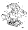
- Fig. 2 shows the same torso 1 in an exploded view, where more components can be seen.
- a top cover 1a (preferably compliant for resuscitation practice), side covers 1 b and a bottom cover 1c constitute the outer parts of the torso 1, in addition to the imitated skin.
- the bottom cover 1 c makes the back part of the torso.
- Substantially parallel to the bottom part 1c is a manikin main board 3 arranged.
- the main board 3 includes various electrical devices for the control of various manikin features. The main board 3 will be further described with reference to Fig. 5 .
- a cooling plate 5 is arranged adjacent and over the main board 3.
- the cooling plate 5 is made of aluminum, giving a light weight, yet structural robustness and high thermal conductivity.
- the cooling plate 5 comprises attachment flanges 5a for the attachment of the manikin arms (not shown), a head (neck) attachment flange 5b and pelvis attachment flanges 5c. In stead of the pelvis attachment flanges 5c, one could also imagine a longer cooling plate 5 with thigh attachment flanges (not shown), or even one or more plates (or other elements) between the cooling plate 5 and thigh connections.
- Fig. 3 and 4 show the upper and lower side of the cooling plate 5, respectively. With a distance from the plate perimeter there are two apertures 5d and 5e, for the through-flow of cooling air. In connection with the aperture 5e is a particular cooling section 5f of the cooling plate 5.
- the cooling section 5f is thermally coupled to a heat generating CPU through a flexible thermal conductor 5g.
- the CPU has a particular cooling requirement. This will be described in more detail further below.
- a spring reception section in the form of a recess 5h for reception of a heart compression spring (not shown).
- the spring is used to provide flexible resistance to the chest for heart compression practice. Without the plate 5, a dedicated structure with the mechanical strength for the reception of the spring would have to be provided. Thus, with the cooling plate 5, such an additional structure is advantageously avoided. With a good thermal connection between the cooling plate 5 and the spring, the spring could also conduct heat away from the plate 5.
- the cooling plate can preferably be a molded aluminum plate.
- the plurality of plates could preferably be thermally connected. They could for instance be hinged together.
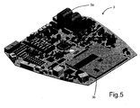
- Fig. 5 illustrates the manikin main board 3 shown in Fig. 2 in further detail.
- the perimeter of the main board 3 is adapted to be fitted in the manikin torso 1.
- Situating the main board 3 in the back of the manikin torso 1 is advantageous as this renders a large main board feasible.
- Close to one corner of the main board 3 there are arranged two large resistors 3a for the dissipation of the electrical energy received from a defibrillator (not shown).
- the energy from a defibrillator is dissipated in a controlled manner, and the nearby arranged cooling plate 5 will spread the generated heat throughout the torso 1.
- the use of a defibrillator will result in a periodic effect of 12 W dissipated in the resistors 3a. Under normal operation, this main board 3 will dissipate about 12 W.
- many of the most heat-generating components are arranged in the same area on the main board 3.
- One would think such an arrangement is a drawback, as the elements will heat each other.
- this configuration renders it possible to direct the air flow from a fan 11 ( Fig. 6 ) directly onto the warmest components.
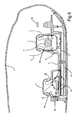
- Fig. 6 is a cross section view showing the arrangement of the cooling plate 5 with respect to the manikin main board 3 and the bottom cover 1c.
- the top cover shown in Fig. 2 is omitted in this figure.
- a layer of imitated skin 7 is arranged around the covers 1 a, 1 b, 1c of the torso 1, substantially entrapping the air inside.
- the main board 3 is arranged between the cooling plate 5 and the bottom cover 1c.
- a space 9 is confined between the main board 3 and the cooling plate 5.
- the air in this space 9 is thus heated by the various electric elements on the main board 3. This heat is then transferred to the cooling plate 5.
- the cooling plate 5 is provided with two apertures 5d and 5e.
- a small fan 11 is arranged in the aperture 5d to provide a flow of air into the space 9 through the aperture 5d. The air thus flows from the air space in the torso 1, into the space 9 between the main board 3 and the cooling plate 5, and finally out back through aperture 5d as heated air.
- the fan 11 is advantageously controlled in order to provide air flow through the space 9 when necessary.
- the trainee will listen for body sounds, such as heart sounds or lunge sounds.
- the fan 11 may produce a disturbing sound. Therefore, in an embodiment according to the invention, the manikin comprises sensors for sensing the presence of medical listening apparatuses, such as a stethoscope.
- the control of the fan 11 is adapted to stop the fan 11 for a short period of time, in order to avoid disturbing such a listening action.
- the temperature of critical electrical elements should preferably be monitored in order to start the fan 11 before any critical temperatures are reached.
- the cooling plate 5 has a particular cooling section 5f that is arranged directly adjacent a main board CPU 3b (central processing unit).
- the cooling section 5f is a plate section with a lower elevation than the opening of the aperture 5e, with the air flowing laterally over the cooling section 5f.
- the cooling section 5f is cooled particularly efficiently.
- the cooling section 5f is in thermal contact with the CPU 3b through a flexible thermal conductor 13a and an aluminum plate 13b. This direct thermal contact between the cooling plate 5 and the CPU 3b provides for an efficient removal of the heat generated by the CPU 3b.
- the cooling plate 5 constitutes part of a Faraday cage that surrounds the main board 3.
- a Faraday cage is an efficient means to ensure such compatibility.
- the cooling plate 5 made of metal, such as aluminum, it can be part of such a Faraday cage, thereby fulfilling yet another purpose.
- the Faraday cage must be completed, preferably by the bottom cover 1 c, in order to encapsulate the main board 3 completely.
- the size of the cooling plate is at least 1 ⁇ 2 of the width of the torso.
- efficient heat transmission from the plate 5 to the air in the torso 1 is provided.
- the large area ensures an even distribution of the heat inside the torso, making the torso skin more or less equally warm at all areas. Particular locations that are exceptionally warm will result in an unrealistic experience for the trainee.
Landscapes
- Engineering & Computer Science (AREA)
- Physics & Mathematics (AREA)
- General Physics & Mathematics (AREA)
- Mathematical Analysis (AREA)
- Mathematical Physics (AREA)
- Chemical & Material Sciences (AREA)
- General Health & Medical Sciences (AREA)
- Medical Informatics (AREA)
- Medicinal Chemistry (AREA)
- Algebra (AREA)
- Computational Mathematics (AREA)
- Microelectronics & Electronic Packaging (AREA)
- Thermal Sciences (AREA)
- Mathematical Optimization (AREA)
- Health & Medical Sciences (AREA)
- Pure & Applied Mathematics (AREA)
- Business, Economics & Management (AREA)
- Educational Administration (AREA)
- Educational Technology (AREA)
- Theoretical Computer Science (AREA)
- Thermotherapy And Cooling Therapy Devices (AREA)
- Instructional Devices (AREA)
- Manipulator (AREA)
- Toys (AREA)
- Cooling Or The Like Of Electrical Apparatus (AREA)
Claims (15)
- Puppe zum Training von medizinischem Personal und Ähnlichem, umfassend elektrische Schaltkreise zum Fühlen von Eingabeparametern und Steuern von Ausgabeparametern, dadurch gekennzeichnet, dass- sie eine Platte (5) mit Metall zum Abführen der vom elektronischen Schaltkreis erzeugten Hitze, weg von dem Schaltkreis, umfasst,- die Platte als strukturelles Element dient, indem sie direkt oder indirekt mit zumindest einem aus einer Gruppe verbunden ist, welche aus Schenkeln, Becken, Hals (Kopf) und Armen besteht;- wobei die Platte zumindest einen Teil eines eine Hauptplatine (3) der Puppe umgebenden Faradayischen Käfigs bildet.
- Puppe nach einem der vorangegangenen Ansprüche, dadurch gekennzeichnet, dass die Platte (5) im Wesentlichen parallel zur elektrischen Hauptplatine zur Ableitung von durch die Hauptplatine (3) erzeugter Hitze angeordnet ist.
- Puppe nach einem der vorhergehenden Ansprüche, dadurch gekennzeichnet, dass die Platte (5) zur Zirkulation von Luft von einer Seite der Platte zur anderen angeordnet ist.
- Puppe nach einem der vorhergehenden Ansprüche, dadurch gekennzeichnet, dass die Platte (5) zumindest ein Loch (5d, 5e) zum Durchfluss von kühlender Luft umfasst.
- Puppe nach Anspruch 4, dadurch gekennzeichnet, dass ein Lüfter (11) in Verbindung mit der Platte angeordnet ist, um einen Luftzug durch zumindest eines der Löcher (5d, 5e) bereitzustellen.
- Puppe nach einem der Ansprüche 3 bis 5, dadurch gekennzeichnet, dass die Platte (5) derart angeordnet ist, dass die kühlende Luft in den Raum (9) zwischen der Platte (5) und der Hauptplatine (3) fließt.
- Puppe nach einem der Ansprüche 4 bis 6, dadurch gekennzeichnet, dass ein Element auf der Hauptplatine (3), welches besonders viel Hitze erzeugt, und ein Loch (5e) in der Kühlplatte in korrespondieren Positionen angeordnet sind, sodass die kühlende Luft direkt zu dem Element fließt.
- Puppe nach einem der vorhergehenden Ansprüche, dadurch gekennzeichnet, dass die Platte (5) in thermischen Kontakt mit den wärmeerzeugenden Schaltkreisen ist.
- Puppe nach einem der vorhergehenden Ansprüche, dadurch gekennzeichnet, dass im Wesentlichen sämtliche durch die Puppe produzierte Wärme zur Umgebung durch Wärmeleitung durch die äußeren Teile der Puppe, wie eine nachgebildete Haut (7), geführt wird.
- Puppe nach Anspruch 4, dadurch gekennzeichnet, dass das Loch (5d, 5e) mit einem Metallgitter abgedeckt ist, wobei das Gitter einen Teil des Faradayschen Käfigs bildet, und durch welches Luft frei fließen kann.
- Puppe nach Anspruch 5, dadurch gekennzeichnet, dass sie mit Fühlmitteln zum Fühlen der Anwesenheit eines Hörapparates, z. B. eines Stethoskops, versehen ist, und dass der Lüfter (11) dazu ausgelegt ist, während der Anwesenheit eines solchen Hörapparates ausgeschaltet zu sein.
- Puppe nach einem der vorhergehenden Ansprüche, dadurch gekennzeichnet, dass die Platte (5) im Torso (1) der Puppe angeordnet ist und eine Breite von zumindest der halben Breite des Torsos aufweist.
- Puppe nach einem der vorhergehenden Ansprüche, dadurch gekennzeichnet, dass die Platte (5) mit einem Empfangsabschnitt für eine Herzkompressionswiderstandsfeder angeordnet ist.
- Puppe nach einem der vorhergehenden Ansprüche, dadurch gekennzeichnet, dass die Platte (5) eine einer Vielzahl solcher Kühlplatten ist.
- Puppe nach Anspruch 14, dadurch gekennzeichnet, dass zumindest zwei der Platten thermisch verbunden sind.
Applications Claiming Priority (3)
| Application Number | Priority Date | Filing Date | Title |
|---|---|---|---|
| NO20080200A NO20080200L (no) | 2008-01-11 | 2008-01-11 | Mannequin med kjoleplate |
| US643908P | 2008-01-14 | 2008-01-14 | |
| PCT/NO2009/000012 WO2009088305A1 (en) | 2008-01-11 | 2009-01-09 | Manikin with cooling plate |
Publications (3)
| Publication Number | Publication Date |
|---|---|
| EP2243130A1 EP2243130A1 (de) | 2010-10-27 |
| EP2243130A4 EP2243130A4 (de) | 2014-06-11 |
| EP2243130B1 true EP2243130B1 (de) | 2015-07-22 |
Family
ID=40853271
Family Applications (1)
| Application Number | Title | Priority Date | Filing Date |
|---|---|---|---|
| EP09700225.7A Not-in-force EP2243130B1 (de) | 2008-01-11 | 2009-01-09 | Puppe mit kühlplatte |
Country Status (7)
| Country | Link |
|---|---|
| US (1) | US8851898B2 (de) |
| EP (1) | EP2243130B1 (de) |
| JP (1) | JP5303573B2 (de) |
| CN (1) | CN101911152B (de) |
| AU (1) | AU2009203224B2 (de) |
| NO (1) | NO20080200L (de) |
| WO (1) | WO2009088305A1 (de) |
Families Citing this family (4)
| Publication number | Priority date | Publication date | Assignee | Title |
|---|---|---|---|---|
| NO20080200L (no) * | 2008-01-11 | 2009-07-13 | Laerdal Medical As | Mannequin med kjoleplate |
| WO2012035129A2 (en) | 2010-09-17 | 2012-03-22 | Laerdal Medical As | Manikin with cpr hand position detection |
| US9576503B2 (en) | 2013-12-27 | 2017-02-21 | Seattle Children's Hospital | Simulation cart |
| US11074832B2 (en) * | 2017-08-16 | 2021-07-27 | Tellyes Scientific Inc. | Warming of simulated blood using waste heat generated by electronic components |
Family Cites Families (31)
| Publication number | Priority date | Publication date | Assignee | Title |
|---|---|---|---|---|
| US2772664A (en) * | 1953-12-11 | 1956-12-04 | Exxon Research Engineering Co | Fluid flow meter |
| US3209469A (en) * | 1962-03-07 | 1965-10-05 | Harold M James | External cardiac massage training device |
| US3520071A (en) * | 1968-01-29 | 1970-07-14 | Aerojet General Co | Anesthesiological training simulator |
| DE1962083A1 (de) * | 1969-12-11 | 1971-06-16 | Laerdal A S | UEbungsgeraet fuer die Wiederbelebung durch Beatmung und aeussere Herzmassage |
| US3657925A (en) * | 1970-06-01 | 1972-04-25 | Int Rectifier Corp | Positive displacement flowmeter |
| USRE29317E (en) * | 1973-01-29 | 1977-07-26 | Michigan Instruments, Inc. | Pneumatic lung analog |
| SE430925B (sv) * | 1977-11-09 | 1983-12-19 | Gambro Lundia Ab | Flodesmetare |
| DE3049583C2 (de) | 1980-12-31 | 1984-08-16 | Obermayer, Anton, Dipl.-Ing., 7954 Bad Wurzach | Atmungsgerät für die technische Ausbildung von Ärzten, Schwestern und Pflegepersonal |
| US4430893A (en) | 1981-11-16 | 1984-02-14 | Michigan Instruments, Inc. | Pneumatic lung analog for simulation of spontaneous breathing and for testing of ventilatory devices used with spontaneously breathing patients |
| US4430890A (en) * | 1982-05-14 | 1984-02-14 | The United States Of America As Represented By The Secretary Of The Navy | Two layer hydraulic analogy method for testing supersonic gas flows with shock waves |
| GB2191884B (en) | 1986-06-17 | 1990-05-30 | Secr Defence | Improvements in manikins |
| US5137459A (en) * | 1989-10-28 | 1992-08-11 | Mathias Zirm | Device for conducting experimental eye operations |
| US5584701A (en) * | 1992-05-13 | 1996-12-17 | University Of Florida Research Foundation, Incorporated | Self regulating lung for simulated medical procedures |
| JPH08190340A (ja) | 1995-01-10 | 1996-07-23 | Yagami:Kk | 蘇生法教育人体モデル |
| US5873731A (en) * | 1995-10-20 | 1999-02-23 | Eagle Simulation, Inc. | Patient drug recognition system |
| US6443735B1 (en) * | 1996-05-08 | 2002-09-03 | Gaumard Scientific, Inc. | Computerized education system for teaching patient care |
| US8696362B2 (en) * | 1996-05-08 | 2014-04-15 | Gaumard Scientific Company, Inc. | Interactive education system for teaching patient care |
| US7811090B2 (en) * | 1996-05-08 | 2010-10-12 | Gaumard Scientific Company, Inc. | Interactive education system for teaching patient care |
| US6503087B1 (en) * | 1996-05-08 | 2003-01-07 | Gaumard Scientific, Inc. | Interactive education system for teaching patient care |
| IL126783A0 (en) * | 1998-03-05 | 1999-08-17 | M T R E Advanced Technology Lt | System and method for heat control of a living body |
| WO1999045522A1 (de) | 1998-03-05 | 1999-09-10 | Asmund S. Laerdal Medical Gmbh & Co. Betriebs Kg | Modell zum üben der cardiopulmonaren wiederbelebung (cpr) eines menschen |
| JP2000277237A (ja) * | 1999-03-24 | 2000-10-06 | Komatsu Ltd | 基板温度制御プレート及びそれを備える基板温度制御装置 |
| NO310135B1 (no) | 1999-05-31 | 2001-05-28 | Laerdal Medical As | System for å måle og anvende parametere ved utförelse av brystkompresjon i löpet av en livredningssituasjon hhv.treningssituasjon samt anvendelser |
| US6269003B1 (en) * | 1999-12-27 | 2001-07-31 | Wei Wen-Chen | Heat dissipater structure |
| CN1363205A (zh) | 2000-02-17 | 2002-08-07 | 皇家菲利浦电子有限公司 | 具有整体形成的元件夹持装置的热沉 |
| US7976313B2 (en) * | 2000-08-17 | 2011-07-12 | Gaumard Scientific Company, Inc. | Interactive education system for teaching patient care |
| US6577504B1 (en) * | 2000-08-30 | 2003-06-10 | Intel Corporation | Integrated heat sink for different size components with EMI suppression features |
| JP3818084B2 (ja) * | 2000-12-22 | 2006-09-06 | 日立電線株式会社 | 冷却板とその製造方法及びスパッタリングターゲットとその製造方法 |
| NO319063B1 (no) | 2003-10-06 | 2005-06-13 | Laerdal Medical As | Medisinsk pasientsimulator |
| US20090035740A1 (en) * | 2007-07-30 | 2009-02-05 | Monster Medic, Inc. | Systems and methods for remote controlled interactive training and certification |
| NO20080200L (no) * | 2008-01-11 | 2009-07-13 | Laerdal Medical As | Mannequin med kjoleplate |
-
2008
- 2008-01-11 NO NO20080200A patent/NO20080200L/no not_active Application Discontinuation
-
2009
- 2009-01-09 CN CN200980101574.5A patent/CN101911152B/zh not_active Expired - Fee Related
- 2009-01-09 AU AU2009203224A patent/AU2009203224B2/en not_active Ceased
- 2009-01-09 EP EP09700225.7A patent/EP2243130B1/de not_active Not-in-force
- 2009-01-09 JP JP2010542188A patent/JP5303573B2/ja not_active Expired - Fee Related
- 2009-01-09 US US12/810,039 patent/US8851898B2/en not_active Expired - Fee Related
- 2009-01-09 WO PCT/NO2009/000012 patent/WO2009088305A1/en not_active Ceased
Also Published As
| Publication number | Publication date |
|---|---|
| US8851898B2 (en) | 2014-10-07 |
| CN101911152B (zh) | 2012-08-22 |
| US20100291523A1 (en) | 2010-11-18 |
| EP2243130A1 (de) | 2010-10-27 |
| WO2009088305A1 (en) | 2009-07-16 |
| JP2011509439A (ja) | 2011-03-24 |
| NO20080200L (no) | 2009-07-13 |
| AU2009203224B2 (en) | 2014-02-20 |
| CN101911152A (zh) | 2010-12-08 |
| EP2243130A4 (de) | 2014-06-11 |
| JP5303573B2 (ja) | 2013-10-02 |
| AU2009203224A1 (en) | 2009-07-16 |
Similar Documents
| Publication | Publication Date | Title |
|---|---|---|
| EP2243130B1 (de) | Puppe mit kühlplatte | |
| JP5011016B2 (ja) | 電力変換装置 | |
| US7355851B2 (en) | Power adapter with fan assembly and control circuit | |
| ATE551774T1 (de) | Elektrische vorrichtung und kühlsystem | |
| JP2019509844A (ja) | 熱交換モジュールおよび医療用途向けシステム | |
| CN207069924U (zh) | 高功率密度直流转交直流功率转换器的抗流圈模块结构 | |
| US20240090182A1 (en) | Passive Heat Dissipation Power Supply for IT Equipment | |
| KR20160022296A (ko) | 열 관리를 위한 디바이스 커버 | |
| JP2010162204A (ja) | 尿失禁治療用磁気刺激装置 | |
| JP3116870U (ja) | 冷却機能を有する電源供給装置 | |
| RU203464U1 (ru) | Устройство радиоэлектронное теплонагруженное | |
| US7059149B2 (en) | Mobile satellite link terminal | |
| JP5309243B2 (ja) | 電力変換装置 | |
| JP2000126874A (ja) | ハウジングユニット | |
| JP5611116B2 (ja) | 電源装置 | |
| FR3086494B1 (fr) | Systeme de bandes electriques modulaires et universelles | |
| EP1517329A3 (de) | Kühler und elektrisches Gerät augestattet mit diesem Kühler | |
| JP6213356B2 (ja) | 電源装置 | |
| JP2012044038A (ja) | 電子機器の放熱構造 | |
| JP2019107202A (ja) | 身体冷暖房装置 | |
| CN213484611U (zh) | 电机安装座 | |
| JP5703343B2 (ja) | 電力変換装置 | |
| CN208779500U (zh) | 隔磁结构和电磁烹饪设备 | |
| JP6674867B2 (ja) | 電力変換装置 | |
| JPH0581874U (ja) | ドットマトリクス発光表示体装置 |
Legal Events
| Date | Code | Title | Description |
|---|---|---|---|
| PUAI | Public reference made under article 153(3) epc to a published international application that has entered the european phase |
Free format text: ORIGINAL CODE: 0009012 |
|
| 17P | Request for examination filed |
Effective date: 20100811 |
|
| AK | Designated contracting states |
Kind code of ref document: A1 Designated state(s): AT BE BG CH CY CZ DE DK EE ES FI FR GB GR HR HU IE IS IT LI LT LU LV MC MK MT NL NO PL PT RO SE SI SK TR |
|
| AX | Request for extension of the european patent |
Extension state: AL BA RS |
|
| DAX | Request for extension of the european patent (deleted) | ||
| A4 | Supplementary search report drawn up and despatched |
Effective date: 20140509 |
|
| RIC1 | Information provided on ipc code assigned before grant |
Ipc: G09B 23/28 20060101AFI20140505BHEP Ipc: G09B 23/30 20060101ALI20140505BHEP |
|
| GRAP | Despatch of communication of intention to grant a patent |
Free format text: ORIGINAL CODE: EPIDOSNIGR1 |
|
| RIC1 | Information provided on ipc code assigned before grant |
Ipc: H05K 7/20 20060101ALI20150310BHEP Ipc: G09B 23/30 20060101AFI20150310BHEP |
|
| INTG | Intention to grant announced |
Effective date: 20150409 |
|
| GRAS | Grant fee paid |
Free format text: ORIGINAL CODE: EPIDOSNIGR3 |
|
| GRAA | (expected) grant |
Free format text: ORIGINAL CODE: 0009210 |
|
| AK | Designated contracting states |
Kind code of ref document: B1 Designated state(s): AT BE BG CH CY CZ DE DK EE ES FI FR GB GR HR HU IE IS IT LI LT LU LV MC MK MT NL NO PL PT RO SE SI SK TR |
|
| REG | Reference to a national code |
Ref country code: GB Ref legal event code: FG4D |
|
| REG | Reference to a national code |
Ref country code: CH Ref legal event code: EP |
|
| REG | Reference to a national code |
Ref country code: IE Ref legal event code: FG4D |
|
| REG | Reference to a national code |
Ref country code: AT Ref legal event code: REF Ref document number: 738290 Country of ref document: AT Kind code of ref document: T Effective date: 20150815 |
|
| REG | Reference to a national code |
Ref country code: DE Ref legal event code: R096 Ref document number: 602009032326 Country of ref document: DE |
|
| REG | Reference to a national code |
Ref country code: FR Ref legal event code: PLFP Year of fee payment: 8 |
|
| REG | Reference to a national code |
Ref country code: AT Ref legal event code: MK05 Ref document number: 738290 Country of ref document: AT Kind code of ref document: T Effective date: 20150722 |
|
| REG | Reference to a national code |
Ref country code: LT Ref legal event code: MG4D |
|
| REG | Reference to a national code |
Ref country code: NL Ref legal event code: MP Effective date: 20150722 |
|
| PG25 | Lapsed in a contracting state [announced via postgrant information from national office to epo] |
Ref country code: LT Free format text: LAPSE BECAUSE OF FAILURE TO SUBMIT A TRANSLATION OF THE DESCRIPTION OR TO PAY THE FEE WITHIN THE PRESCRIBED TIME-LIMIT Effective date: 20150722 Ref country code: NO Free format text: LAPSE BECAUSE OF FAILURE TO SUBMIT A TRANSLATION OF THE DESCRIPTION OR TO PAY THE FEE WITHIN THE PRESCRIBED TIME-LIMIT Effective date: 20151022 Ref country code: LV Free format text: LAPSE BECAUSE OF FAILURE TO SUBMIT A TRANSLATION OF THE DESCRIPTION OR TO PAY THE FEE WITHIN THE PRESCRIBED TIME-LIMIT Effective date: 20150722 Ref country code: GR Free format text: LAPSE BECAUSE OF FAILURE TO SUBMIT A TRANSLATION OF THE DESCRIPTION OR TO PAY THE FEE WITHIN THE PRESCRIBED TIME-LIMIT Effective date: 20151023 Ref country code: FI Free format text: LAPSE BECAUSE OF FAILURE TO SUBMIT A TRANSLATION OF THE DESCRIPTION OR TO PAY THE FEE WITHIN THE PRESCRIBED TIME-LIMIT Effective date: 20150722 |
|
| PG25 | Lapsed in a contracting state [announced via postgrant information from national office to epo] |
Ref country code: SE Free format text: LAPSE BECAUSE OF FAILURE TO SUBMIT A TRANSLATION OF THE DESCRIPTION OR TO PAY THE FEE WITHIN THE PRESCRIBED TIME-LIMIT Effective date: 20150722 Ref country code: HR Free format text: LAPSE BECAUSE OF FAILURE TO SUBMIT A TRANSLATION OF THE DESCRIPTION OR TO PAY THE FEE WITHIN THE PRESCRIBED TIME-LIMIT Effective date: 20150722 Ref country code: IS Free format text: LAPSE BECAUSE OF FAILURE TO SUBMIT A TRANSLATION OF THE DESCRIPTION OR TO PAY THE FEE WITHIN THE PRESCRIBED TIME-LIMIT Effective date: 20151122 Ref country code: AT Free format text: LAPSE BECAUSE OF FAILURE TO SUBMIT A TRANSLATION OF THE DESCRIPTION OR TO PAY THE FEE WITHIN THE PRESCRIBED TIME-LIMIT Effective date: 20150722 Ref country code: PT Free format text: LAPSE BECAUSE OF FAILURE TO SUBMIT A TRANSLATION OF THE DESCRIPTION OR TO PAY THE FEE WITHIN THE PRESCRIBED TIME-LIMIT Effective date: 20151123 Ref country code: ES Free format text: LAPSE BECAUSE OF FAILURE TO SUBMIT A TRANSLATION OF THE DESCRIPTION OR TO PAY THE FEE WITHIN THE PRESCRIBED TIME-LIMIT Effective date: 20150722 Ref country code: PL Free format text: LAPSE BECAUSE OF FAILURE TO SUBMIT A TRANSLATION OF THE DESCRIPTION OR TO PAY THE FEE WITHIN THE PRESCRIBED TIME-LIMIT Effective date: 20150722 |
|
| PGFP | Annual fee paid to national office [announced via postgrant information from national office to epo] |
Ref country code: FR Payment date: 20151208 Year of fee payment: 8 |
|
| REG | Reference to a national code |
Ref country code: DE Ref legal event code: R097 Ref document number: 602009032326 Country of ref document: DE |
|
| PG25 | Lapsed in a contracting state [announced via postgrant information from national office to epo] |
Ref country code: SK Free format text: LAPSE BECAUSE OF FAILURE TO SUBMIT A TRANSLATION OF THE DESCRIPTION OR TO PAY THE FEE WITHIN THE PRESCRIBED TIME-LIMIT Effective date: 20150722 Ref country code: IT Free format text: LAPSE BECAUSE OF FAILURE TO SUBMIT A TRANSLATION OF THE DESCRIPTION OR TO PAY THE FEE WITHIN THE PRESCRIBED TIME-LIMIT Effective date: 20150722 Ref country code: DK Free format text: LAPSE BECAUSE OF FAILURE TO SUBMIT A TRANSLATION OF THE DESCRIPTION OR TO PAY THE FEE WITHIN THE PRESCRIBED TIME-LIMIT Effective date: 20150722 Ref country code: EE Free format text: LAPSE BECAUSE OF FAILURE TO SUBMIT A TRANSLATION OF THE DESCRIPTION OR TO PAY THE FEE WITHIN THE PRESCRIBED TIME-LIMIT Effective date: 20150722 Ref country code: CZ Free format text: LAPSE BECAUSE OF FAILURE TO SUBMIT A TRANSLATION OF THE DESCRIPTION OR TO PAY THE FEE WITHIN THE PRESCRIBED TIME-LIMIT Effective date: 20150722 |
|
| PGFP | Annual fee paid to national office [announced via postgrant information from national office to epo] |
Ref country code: DE Payment date: 20160105 Year of fee payment: 8 |
|
| PLBE | No opposition filed within time limit |
Free format text: ORIGINAL CODE: 0009261 |
|
| STAA | Information on the status of an ep patent application or granted ep patent |
Free format text: STATUS: NO OPPOSITION FILED WITHIN TIME LIMIT |
|
| PG25 | Lapsed in a contracting state [announced via postgrant information from national office to epo] |
Ref country code: BE Free format text: LAPSE BECAUSE OF NON-PAYMENT OF DUE FEES Effective date: 20160131 Ref country code: RO Free format text: LAPSE BECAUSE OF FAILURE TO SUBMIT A TRANSLATION OF THE DESCRIPTION OR TO PAY THE FEE WITHIN THE PRESCRIBED TIME-LIMIT Effective date: 20150722 |
|
| PGFP | Annual fee paid to national office [announced via postgrant information from national office to epo] |
Ref country code: GB Payment date: 20160106 Year of fee payment: 8 |
|
| 26N | No opposition filed |
Effective date: 20160425 |
|
| PG25 | Lapsed in a contracting state [announced via postgrant information from national office to epo] |
Ref country code: LU Free format text: LAPSE BECAUSE OF FAILURE TO SUBMIT A TRANSLATION OF THE DESCRIPTION OR TO PAY THE FEE WITHIN THE PRESCRIBED TIME-LIMIT Effective date: 20160109 Ref country code: SI Free format text: LAPSE BECAUSE OF FAILURE TO SUBMIT A TRANSLATION OF THE DESCRIPTION OR TO PAY THE FEE WITHIN THE PRESCRIBED TIME-LIMIT Effective date: 20150722 |
|
| REG | Reference to a national code |
Ref country code: CH Ref legal event code: PL |
|
| PG25 | Lapsed in a contracting state [announced via postgrant information from national office to epo] |
Ref country code: MC Free format text: LAPSE BECAUSE OF FAILURE TO SUBMIT A TRANSLATION OF THE DESCRIPTION OR TO PAY THE FEE WITHIN THE PRESCRIBED TIME-LIMIT Effective date: 20150722 |
|
| PG25 | Lapsed in a contracting state [announced via postgrant information from national office to epo] |
Ref country code: LI Free format text: LAPSE BECAUSE OF NON-PAYMENT OF DUE FEES Effective date: 20160131 Ref country code: CH Free format text: LAPSE BECAUSE OF NON-PAYMENT OF DUE FEES Effective date: 20160131 |
|
| REG | Reference to a national code |
Ref country code: IE Ref legal event code: MM4A |
|
| PG25 | Lapsed in a contracting state [announced via postgrant information from national office to epo] |
Ref country code: BE Free format text: LAPSE BECAUSE OF FAILURE TO SUBMIT A TRANSLATION OF THE DESCRIPTION OR TO PAY THE FEE WITHIN THE PRESCRIBED TIME-LIMIT Effective date: 20150722 |
|
| PG25 | Lapsed in a contracting state [announced via postgrant information from national office to epo] |
Ref country code: IE Free format text: LAPSE BECAUSE OF NON-PAYMENT OF DUE FEES Effective date: 20160109 |
|
| PG25 | Lapsed in a contracting state [announced via postgrant information from national office to epo] |
Ref country code: NL Free format text: LAPSE BECAUSE OF FAILURE TO SUBMIT A TRANSLATION OF THE DESCRIPTION OR TO PAY THE FEE WITHIN THE PRESCRIBED TIME-LIMIT Effective date: 20150722 |
|
| REG | Reference to a national code |
Ref country code: DE Ref legal event code: R119 Ref document number: 602009032326 Country of ref document: DE |
|
| PG25 | Lapsed in a contracting state [announced via postgrant information from national office to epo] |
Ref country code: MT Free format text: LAPSE BECAUSE OF FAILURE TO SUBMIT A TRANSLATION OF THE DESCRIPTION OR TO PAY THE FEE WITHIN THE PRESCRIBED TIME-LIMIT Effective date: 20150722 |
|
| GBPC | Gb: european patent ceased through non-payment of renewal fee |
Effective date: 20170109 |
|
| REG | Reference to a national code |
Ref country code: FR Ref legal event code: ST Effective date: 20170929 |
|
| PG25 | Lapsed in a contracting state [announced via postgrant information from national office to epo] |
Ref country code: FR Free format text: LAPSE BECAUSE OF NON-PAYMENT OF DUE FEES Effective date: 20170131 |
|
| PG25 | Lapsed in a contracting state [announced via postgrant information from national office to epo] |
Ref country code: DE Free format text: LAPSE BECAUSE OF NON-PAYMENT OF DUE FEES Effective date: 20170801 Ref country code: GB Free format text: LAPSE BECAUSE OF NON-PAYMENT OF DUE FEES Effective date: 20170109 |
|
| PG25 | Lapsed in a contracting state [announced via postgrant information from national office to epo] |
Ref country code: HU Free format text: LAPSE BECAUSE OF FAILURE TO SUBMIT A TRANSLATION OF THE DESCRIPTION OR TO PAY THE FEE WITHIN THE PRESCRIBED TIME-LIMIT; INVALID AB INITIO Effective date: 20090109 Ref country code: CY Free format text: LAPSE BECAUSE OF FAILURE TO SUBMIT A TRANSLATION OF THE DESCRIPTION OR TO PAY THE FEE WITHIN THE PRESCRIBED TIME-LIMIT Effective date: 20150722 |
|
| PG25 | Lapsed in a contracting state [announced via postgrant information from national office to epo] |
Ref country code: MK Free format text: LAPSE BECAUSE OF FAILURE TO SUBMIT A TRANSLATION OF THE DESCRIPTION OR TO PAY THE FEE WITHIN THE PRESCRIBED TIME-LIMIT Effective date: 20150722 Ref country code: MT Free format text: LAPSE BECAUSE OF FAILURE TO SUBMIT A TRANSLATION OF THE DESCRIPTION OR TO PAY THE FEE WITHIN THE PRESCRIBED TIME-LIMIT Effective date: 20160131 Ref country code: TR Free format text: LAPSE BECAUSE OF FAILURE TO SUBMIT A TRANSLATION OF THE DESCRIPTION OR TO PAY THE FEE WITHIN THE PRESCRIBED TIME-LIMIT Effective date: 20150722 |
|
| PG25 | Lapsed in a contracting state [announced via postgrant information from national office to epo] |
Ref country code: BG Free format text: LAPSE BECAUSE OF FAILURE TO SUBMIT A TRANSLATION OF THE DESCRIPTION OR TO PAY THE FEE WITHIN THE PRESCRIBED TIME-LIMIT Effective date: 20150722 |