EP2242905B1 - Mounting base and scroll compressor incorporating same - Google Patents
Mounting base and scroll compressor incorporating same Download PDFInfo
- Publication number
- EP2242905B1 EP2242905B1 EP09701761.0A EP09701761A EP2242905B1 EP 2242905 B1 EP2242905 B1 EP 2242905B1 EP 09701761 A EP09701761 A EP 09701761A EP 2242905 B1 EP2242905 B1 EP 2242905B1
- Authority
- EP
- European Patent Office
- Prior art keywords
- scroll compressor
- mounting
- mounting base
- rails
- support
- Prior art date
- Legal status (The legal status is an assumption and is not a legal conclusion. Google has not performed a legal analysis and makes no representation as to the accuracy of the status listed.)
- Active
Links
Images


Classifications
-
- F—MECHANICAL ENGINEERING; LIGHTING; HEATING; WEAPONS; BLASTING
- F04—POSITIVE - DISPLACEMENT MACHINES FOR LIQUIDS; PUMPS FOR LIQUIDS OR ELASTIC FLUIDS
- F04C—ROTARY-PISTON, OR OSCILLATING-PISTON, POSITIVE-DISPLACEMENT MACHINES FOR LIQUIDS; ROTARY-PISTON, OR OSCILLATING-PISTON, POSITIVE-DISPLACEMENT PUMPS
- F04C18/00—Rotary-piston pumps specially adapted for elastic fluids
- F04C18/02—Rotary-piston pumps specially adapted for elastic fluids of arcuate-engagement type, i.e. with circular translatory movement of co-operating members, each member having the same number of teeth or tooth-equivalents
- F04C18/0207—Rotary-piston pumps specially adapted for elastic fluids of arcuate-engagement type, i.e. with circular translatory movement of co-operating members, each member having the same number of teeth or tooth-equivalents both members having co-operating elements in spiral form
- F04C18/0215—Rotary-piston pumps specially adapted for elastic fluids of arcuate-engagement type, i.e. with circular translatory movement of co-operating members, each member having the same number of teeth or tooth-equivalents both members having co-operating elements in spiral form where only one member is moving
-
- F—MECHANICAL ENGINEERING; LIGHTING; HEATING; WEAPONS; BLASTING
- F01—MACHINES OR ENGINES IN GENERAL; ENGINE PLANTS IN GENERAL; STEAM ENGINES
- F01C—ROTARY-PISTON OR OSCILLATING-PISTON MACHINES OR ENGINES
- F01C21/00—Component parts, details or accessories not provided for in groups F01C1/00 - F01C20/00
- F01C21/007—General arrangements of parts; Frames and supporting elements
-
- F—MECHANICAL ENGINEERING; LIGHTING; HEATING; WEAPONS; BLASTING
- F04—POSITIVE - DISPLACEMENT MACHINES FOR LIQUIDS; PUMPS FOR LIQUIDS OR ELASTIC FLUIDS
- F04C—ROTARY-PISTON, OR OSCILLATING-PISTON, POSITIVE-DISPLACEMENT MACHINES FOR LIQUIDS; ROTARY-PISTON, OR OSCILLATING-PISTON, POSITIVE-DISPLACEMENT PUMPS
- F04C23/00—Combinations of two or more pumps, each being of rotary-piston or oscillating-piston type, specially adapted for elastic fluids; Pumping installations specially adapted for elastic fluids; Multi-stage pumps specially adapted for elastic fluids
- F04C23/001—Combinations of two or more pumps, each being of rotary-piston or oscillating-piston type, specially adapted for elastic fluids; Pumping installations specially adapted for elastic fluids; Multi-stage pumps specially adapted for elastic fluids of similar working principle
-
- F—MECHANICAL ENGINEERING; LIGHTING; HEATING; WEAPONS; BLASTING
- F04—POSITIVE - DISPLACEMENT MACHINES FOR LIQUIDS; PUMPS FOR LIQUIDS OR ELASTIC FLUIDS
- F04C—ROTARY-PISTON, OR OSCILLATING-PISTON, POSITIVE-DISPLACEMENT MACHINES FOR LIQUIDS; ROTARY-PISTON, OR OSCILLATING-PISTON, POSITIVE-DISPLACEMENT PUMPS
- F04C23/00—Combinations of two or more pumps, each being of rotary-piston or oscillating-piston type, specially adapted for elastic fluids; Pumping installations specially adapted for elastic fluids; Multi-stage pumps specially adapted for elastic fluids
- F04C23/008—Hermetic pumps
-
- F—MECHANICAL ENGINEERING; LIGHTING; HEATING; WEAPONS; BLASTING
- F04—POSITIVE - DISPLACEMENT MACHINES FOR LIQUIDS; PUMPS FOR LIQUIDS OR ELASTIC FLUIDS
- F04C—ROTARY-PISTON, OR OSCILLATING-PISTON, POSITIVE-DISPLACEMENT MACHINES FOR LIQUIDS; ROTARY-PISTON, OR OSCILLATING-PISTON, POSITIVE-DISPLACEMENT PUMPS
- F04C2230/00—Manufacture
- F04C2230/60—Assembly methods
- F04C2230/603—Centering; Aligning
-
- F—MECHANICAL ENGINEERING; LIGHTING; HEATING; WEAPONS; BLASTING
- F04—POSITIVE - DISPLACEMENT MACHINES FOR LIQUIDS; PUMPS FOR LIQUIDS OR ELASTIC FLUIDS
- F04C—ROTARY-PISTON, OR OSCILLATING-PISTON, POSITIVE-DISPLACEMENT MACHINES FOR LIQUIDS; ROTARY-PISTON, OR OSCILLATING-PISTON, POSITIVE-DISPLACEMENT PUMPS
- F04C2230/00—Manufacture
- F04C2230/60—Assembly methods
- F04C2230/604—Mounting devices for pumps or compressors
-
- F—MECHANICAL ENGINEERING; LIGHTING; HEATING; WEAPONS; BLASTING
- F04—POSITIVE - DISPLACEMENT MACHINES FOR LIQUIDS; PUMPS FOR LIQUIDS OR ELASTIC FLUIDS
- F04C—ROTARY-PISTON, OR OSCILLATING-PISTON, POSITIVE-DISPLACEMENT MACHINES FOR LIQUIDS; ROTARY-PISTON, OR OSCILLATING-PISTON, POSITIVE-DISPLACEMENT PUMPS
- F04C2240/00—Components
- F04C2240/70—Use of multiplicity of similar components; Modular construction
Definitions
- the present invention relates to scroll compressors for compressing refrigerant and more particularly to the mounting bases of such scroll compressors, which may be used to mount the scroll compressor on a set of rails.
- a scroll compressor is a certain type of compressor that is used to compress refrigerant for such applications as refrigeration, air conditioning, industrial cooling and freezer applications, and/or other applications where compressed fluid may be used.
- Such prior scroll compressors are known, for example, as exemplified in U.S. Patent Nos. 6,398,530 to Hasemann ; 6,814,551, to Kammhoff et al. ; 6,960,070 to Kammhoff et al. ; and 7,112,046 to Kammhoff et al. , all of which are assigned to a Bitzer entity closely related to the present assignee.
- the present disclosure pertains to improvements that can be implemented in these or other scroll compressor designs.
- scroll compressors conventionally include an outer housing having a scroll compressor contained therein.
- a scroll compressor includes first and second scroll compressor members.
- a first compressor member is typically arranged stationary and fixed in the outer housing.
- a second scroll compressor member is moveable relative to the first scroll compressor member in order to compress refrigerant between respective scroll ribs which rise above the respective bases and engage in one another.
- the moveable scroll compressor member is driven about an orbital path about a central axis for the purposes of compressing refrigerant.
- An appropriate drive unit typically an electric motor, is provided usually within the same housing to drive the movable scroll member.
- Scroll compressor assemblies typically include a mounting base, which supports the scroll compressor.
- a mounting base in the form of a mounting plate is shown in U.S. 6,761,541 B1 .
- the mounting plate includes a central aperture which supports a scroll compressor and upwardly and downwardly depending flanges around the parameter that provide for support and mounting to a pair of rails.
- US 6,761,541 B1 discloses a scroll compressor assembly and a mounting plate for a scroll compressor having a mounting base having at least two tracks as well as at least two support ribs extending transversely between the at least two tracks.
- JP 63-183484 U and JP 03-102072 U disclose a scroll compressor assembly and a mounting plate for a scroll compressor having three arms reinforced by a rib extending transverse to each arm.
- the present invention is directed toward improvements over the existing mounting base designs, such as shown in US 6,761,541 B1 .
- the invention is defined by the subject matter of claim 1.
- a scroll compressor assembly has a support rib formed into the mounting base.
- the mounting base may either support the scroll compressor housing as a separate component part or may integrally form part of the scroll compressor housing.
- a scroll compressor assembly in accordance therewith includes a scroll compressor and a mounting base for supporting the scroll compressor.
- the mounting base has at least two tracks, an outer peripheral edge and at least one support rib.
- the at least one support rib is formed into the mounting base and projects in spaced relation to the outer peripheral edge.
- a mounting plate which can provide for a mounting base for a scroll compressor comprises a unitary formed metal component part having a body portion with four sides. A central region of the mounting plate forms a nest for support of the scroll compressor. A pair of tracks in the form of flanges depend downwardly from the opposing sides of the body portion. A pair of support ribs formed into the body portion extend transversely between the flanges. The support ribs can have a generally U-shaped cross section.
- a scroll compressor assembly comprises: a scroll compressor; a mounting base for supporting the scroll compressor, the mounting base having at least two tracks, an outer peripheral edge and at least one support rib, the at least one support rib projecting in spaced relation to the outer peripheral edge and the other features as defined in claim 1.
- the at least one support rib extends transversely between the at least two tracks.
- the scroll compressor assembly according to the invention further comprises at least two support ribs, including a support rib on opposing sides of the scroll compressor, each support rib extending transversely between the at least two tracks.
- the mounting base comprises a formed metal plate
- the at least one support rib comprises a raised ridge formed into a body of the base, including a linear segment extending between two rounded ends, the linear segment having a generally U-shaped cross section.
- the mounting base comprises a formed metal plate having four sides surrounding an annular nest region wherein the scroll compressor is arranged, and four corner regions, each corner region located at an intersection between two adjacent sides, each corner region having a mounting hole, and wherein the support ribs project on the outside of pairs of the mounting holes such that each support rib projects in a region generally between two of the mounting holes and one of the sides connecting corner regions for said two mounting holes.
- each mounting rib terminates prior to reaching the mounting holes as the mounting ribs extend transversely.
- each track comprises a flange depending downwardly from a body of the metal plate at the peripheral edge.
- the mounting base comprises a formed metal plate having four sides surrounding an annular nest region wherein the scroll compressor is arranged, and four corner regions, each corner region located at an intersection between two adjacent sides, each corner region having a mounting hole, and wherein the support ribs project on the outside of pairs of the mounting holes such that each support rib projects in a region generally between two of the mounting holes and one of the sides connecting corner regions for said two mounting holes, and two holes are provided in each corner.
- the scroll compressor further comprises two mounting rails adapted to be arranged generally parallel, each track locating on a respective one of the rails, and wherein opposed ends of the at least one support rib overlaps the two mounting rails, respectively, when each track is located on a respective one of the rails.
- the scroll compressor comprises a housing containing two scroll compressor bodies and a drive unit operative to facilitate relative movement between the scroll compressor bodies, the scroll compressor bodies having respective bases and respective scroll ribs that project from the respective bases and which mutually engage for compressing fluid, wherein the mounting base is secured to the housing.
- the scroll compressor comprises a housing containing two scroll compressor bodies and a drive unit operative to facilitate relative movement between the scroll compressor bodies, the scroll compressor bodies having respective bases and respective scroll ribs that project from the respective bases and which mutually engage for compressing fluid, wherein the mounting base is unitarily formed with a shell member of the housing.
- An example of a mounting plate for a scroll compressor comprises a unitary formed metal component part having a body portion with four sides, a central region of the mounting plate forming a nest for support of the scroll compressor, a pair of tracks in the form of flanges depending downwardly from the opposing sides of the body portion, and a pair of support ribs formed into the body portion extending transversely between the flanges, the support ribs having a generally U-shaped cross section.
- each support rib comprises a raised ridge formed into a body of the base.
- the mounting plate has four corner regions, each corner region located at an intersection between two adjacent sides, each corner region having a mounting hole, and wherein the support ribs project on the outside of pairs of the mounting holes such that each support rib projects in a region generally between two of the mounting holes and one of the sides connecting corner regions for said two mounting holes.
- each mounting rib terminates prior to reaching the mounting holes as the mounting ribs extend transversely.
- each flange locates along an outside edge of one of a pair of parallel mounting rails, and wherein opposed ends of the each support rib overlap the two mounting rails, respectively, when the mounting plate is located on the rails.
- each support rib including a generally linear segment extending between opposed rounded ends.
- the body portion is generally planar, and a planar region of the body portion generally surrounds each support rib.
- the nest comprises a ring wall depending upwardly from the body portion.
- the nest comprises a concave receptacle.
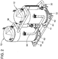
- FIGS. 1-7 An embodiment of the present invention has been illustrated as a scroll compressor assembly 12 incorporating a mounting base 10 as shown in FIGS. 1-7 .
- the scroll compressor assembly 12 generally includes an outer housing 14 that typically comprises one or more stamp-formed sheet steel shell sections 16 that are welded together. Contained within the housing 14 is a drive unit 18 that may take the form of an electrical motor and a pair of scroll compressor bodies to include a fixed scroll compressor body 20 and a movable scroll compressor body 22.
- the scroll compressor bodies 20, 22 have respective bases 24 and respective scroll ribs 26 that project from the respective bases 24 and which mutually engage for compression fluid.
- the drive unit 18 has a rotational output on a drive shaft 28 that is operable to drive the movable scroll compressor body 22 about an orbital path relative to the fixed scroll compressor body 20 and thereby facilitates the compression of fluid. Further details of such a scroll compressor arrangement is further described in the aforementioned patents. Collectively, the housing 14 and the components therein (e.g. the drive units 18, and scroll compressor bodies 20, 22) may be referred to as making up a scroll compressor 30.
- the mounting base 10 supports the weight of the scroll compressor 30 and provides for mounting of the overall scroll compressor assembly 12 to mounting structure shown as a pair of rails 32.
- multiple scroll compressor assemblies 12 can be rail mounted along a common set of the rails 32 and coupled together with conduits connecting respective inlet ports and out ports.
- these conduits 34, 36 fluidically connect the scroll compressor assemblies 12 together for connection to a refrigeration circuit.
- Each of the scroll compressor assemblies 12 are each also commonly mounted on the same rails 32 in a linear array.
- the mounting base 10 serves the functions of supporting the scroll compressor 30 and mounting the scroll compressor 30 to the rails 32.
- the disclosed embodiment of the mounting base can take the form of a stamped sheet metal mounting plate 40.
- This mounting plate 40 can be stamp-formed and cut out from sheet steel.
- the mounting plate can provide a central aperture 44 to provide for a nest 42 in which the lower shell section 16 of the housing 14 can be received and nested.
- this region may be free of an aperture and solid and thereby form the lower most portion of the housing 14 integrally and as a unitary component.
- the mounting base supports the scroll compressor.
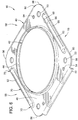
- the mounting plate can include a number of structural features to include a planar body region 46 into which the aperture 44 is formed; an upwardly depending circular ring wall 48 depending upwardly from the body region 46; a pair of mounting tracks that may take the form of flanges 50 depending downwardly from the body region 46 on opposed sides thereof; a pair of support ribs 52 formed into the body region 46 and extending transversely relative to the flanges; and mounting holes 53, 54 formed through the body region 46 for facilitating fastening of the scroll compressor assembly 12 to the rails 32.
- the upwardly bent flange forms a circular ring wall 48 in which the lower most shell section 16 of the compressor housing 14 seats along a circular interface.
- the two components are permanently connected by such means as welding (either spot or circumferentially) and/or brazing.
- the circular wall 48 depends upwardly from the planar body region 46 of the mounting plate 40.
- the mounting plate 40 and body thereof has a generally rectangular configuration to include four arcuate corners 56 and four sides 58.
- An outer peripheral edge 60 runs around the rectangular perimeter of the mounting plate 40 and thereby generally defines its outer boundary.
- At least one and sometimes two mounting holes 53, 54 are provided which can receive a fastener 62 as shown to facilitate fastening and thereby securement of the scroll compressor assembly 12 to the pair of rails 32. This is illustrated with additional detailing in FIGS. 2-5 .
- the mounting plate 40 includes tracks for mounting upon the pair of parallel rails 32, which take the form of mounting flanges 50 in the illustrated embodiment.
- the flanges 50 depend downwardly from the planar body portion 46 on opposed sides 58 at the peripheral edge 60. As shown in FIGS. 2 and 3 , these flanges locate and engage upon the respective outside surfaces of the rails 32. Flanges generally define an underside channel therebetween which receives the rails therebetween. As a result, the scroll compressor assembly and/or the mounting plate 40 may be slid linearly on the rails to the appropriate mounting location during installation.
- the mounting plate 40 also includes at least one and preferably two support ribs 52.
- the support ribs 52 project generally along two opposed sides and generally transversely between the mounting flanges and generally between two different corner regions located at intersections between two adjacent sides.
- the support ribs 52 increase the structural strength and integrity of the mounting plate to prevent the mounting plate from buckling under the weight and operating vibrations that may be caused by the scroll compressor.
- the support ribs 52 interrupt the otherwise thin configuration of the planar body region 46 and thereby increase the strength modulus by increasing the vertical thickness in the cross sectional region of the support rib as shown in FIG. 1 .
- the support ribs 52 can be formed by a raised ridge that projects in spaced relation to the outer peripheral edge 60 toward a projecting tip 66.
- An advantage that may be accomplished with this configuration is two vertically extending thickness regions, each which provides strength enhancement, namely two straight or sloped sides 68 that can extend from the tip 66 to the body region 46.
- this configuration can include a generally U-shaped cross section in which each of the sides 68 provide a significant strength enhancement feature.
- one strengthening rib 52 is provided on each side of the scroll compressor 30 to provide for lateral strength on each side.
- the support ribs 52 extend and overlap the mounting rails 32 so that the strengthening feature is carried across the full length between the rails.
- the support ribs 52 can have a straight segment 70 running the length between opposed rails, with rounded ends 72 capping opposed ends of the straight segment 70.
- the support ribs take the form of a ridge projected upwardly so that the rib does not actually engage or rest upon the rails. Instead, typically the flat underside of the body region 46 will rest upon the rails.
- the ribs 52 can also project on the outside of pairs of mounting holes 53, 54 such that each support rib projects over a range generally between two of the mounting holes and one of the sides connecting corner regions for different mounting holes.
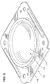
- FIG. 8 an alternative embodiment of the mounting plate 140 is illustrated in which the central region 110 is not aperture, but instead is solid and provides an integral housing section for the housing of the scroll compressor.
- This embodiment provides the same mounting base 112 as the first embodiment and still supports the scroll compressor just like the first embodiment but it is illustrated that the mounting plate 140 may additionally comprise the concave receptacle 114 upon which the remainder of the scroll compressor housing can be built (e.g. a central housing shell section could be welded to the outside or inside of the receptacle).
Landscapes
- Engineering & Computer Science (AREA)
- Mechanical Engineering (AREA)
- General Engineering & Computer Science (AREA)
- Rotary Pumps (AREA)
- Compressor (AREA)
- Applications Or Details Of Rotary Compressors (AREA)
Applications Claiming Priority (2)
| Application Number | Priority Date | Filing Date | Title |
|---|---|---|---|
| US12/015,643 US8142175B2 (en) | 2008-01-17 | 2008-01-17 | Mounting base and scroll compressor incorporating same |
| PCT/US2009/031104 WO2009091891A1 (en) | 2008-01-17 | 2009-01-15 | Mounting base and scroll compressor incorporating same |
Publications (2)
| Publication Number | Publication Date |
|---|---|
| EP2242905A1 EP2242905A1 (en) | 2010-10-27 |
| EP2242905B1 true EP2242905B1 (en) | 2020-09-02 |
Family
ID=40589968
Family Applications (1)
| Application Number | Title | Priority Date | Filing Date |
|---|---|---|---|
| EP09701761.0A Active EP2242905B1 (en) | 2008-01-17 | 2009-01-15 | Mounting base and scroll compressor incorporating same |
Country Status (6)
| Country | Link |
|---|---|
| US (1) | US8142175B2 (https=) |
| EP (1) | EP2242905B1 (https=) |
| JP (1) | JP2011510216A (https=) |
| KR (1) | KR20100123693A (https=) |
| CN (1) | CN101965439B (https=) |
| WO (1) | WO2009091891A1 (https=) |
Families Citing this family (33)
| Publication number | Priority date | Publication date | Assignee | Title |
|---|---|---|---|---|
| US9568002B2 (en) | 2008-01-17 | 2017-02-14 | Bitzer Kuehlmaschinenbau Gmbh | Key coupling and scroll compressor incorporating same |
| US7967581B2 (en) * | 2008-01-17 | 2011-06-28 | Bitzer Kuhlmaschinenbau Gmbh | Shaft mounted counterweight, method and scroll compressor incorporating same |
| US7963753B2 (en) * | 2008-01-17 | 2011-06-21 | Bitzer Kuhlmaschinenbau Gmbh | Scroll compressor bodies with scroll tip seals and extended thrust region |
| US7878780B2 (en) | 2008-01-17 | 2011-02-01 | Bitzer Kuhlmaschinenbau Gmbh | Scroll compressor suction flow path and bearing arrangement features |
| US8133043B2 (en) | 2008-10-14 | 2012-03-13 | Bitzer Scroll, Inc. | Suction duct and scroll compressor incorporating same |
| US8167595B2 (en) | 2008-10-14 | 2012-05-01 | Bitzer Scroll Inc. | Inlet screen and scroll compressor incorporating same |
| EP2389516B1 (en) * | 2009-01-23 | 2024-01-10 | BITZER Kühlmaschinenbau GmbH | Compressors with different volume indexes and method for same |
| US8328543B2 (en) | 2009-04-03 | 2012-12-11 | Bitzer Kuehlmaschinenbau Gmbh | Contoured check valve disc and scroll compressor incorporating same |
| DE102009037010A1 (de) * | 2009-08-11 | 2011-02-17 | Oerlikon Leybold Vacuum Gmbh | Vakuumpumpensystem |
| US8297958B2 (en) * | 2009-09-11 | 2012-10-30 | Bitzer Scroll, Inc. | Optimized discharge port for scroll compressor with tip seals |
| US9080645B2 (en) * | 2010-07-16 | 2015-07-14 | Patton's Medical, Llc | Compressed air device for allowing the expeditious adjustment of drive belts |
| US9181940B2 (en) * | 2012-03-23 | 2015-11-10 | Bitzer Kuehlmaschinenbau Gmbh | Compressor baseplate with stiffening ribs for increased oil volume and rail mounting without spacers |
| ES2929924T3 (es) * | 2012-09-04 | 2022-12-02 | Carrier Corp | Montaje de pies de compresor de refrigeración |
| US10072673B2 (en) * | 2014-08-04 | 2018-09-11 | Powerex-Iwata Air Technology, Inc. | Compressor system |
| JP6407306B2 (ja) * | 2014-12-24 | 2018-10-17 | 日立オートモティブシステムズ株式会社 | 車両用のポンプ装置および車両用のブラケット |
| US10047799B2 (en) * | 2015-04-10 | 2018-08-14 | Emerson Climate Technologies, Inc. | Scroll compressor lower bearing |
| CN105020557B (zh) * | 2015-07-22 | 2018-01-16 | 珠海格力电器股份有限公司 | 一种压缩机安装结构及饮水机 |
| FR3065998B1 (fr) * | 2017-05-03 | 2019-06-28 | Danfoss Commercial Compressors | Compresseur a spirales ayant une plaque de base comportant des premiere et deuxieme parties de rebord cylindriques |
| US10758855B2 (en) | 2017-11-29 | 2020-09-01 | Megadyne Medical Products, Inc. | Smoke evacuation system fluid trap |
| US10758293B2 (en) | 2017-11-29 | 2020-09-01 | Megadyne Medical Products, Inc. | Smoke evacuation device inlet and outlet manifolds |
| US10758856B2 (en) | 2017-11-29 | 2020-09-01 | Megadyne Medical Products, Inc. | Filter medium compression system for smoke evacuation |
| USD886976S1 (en) | 2017-11-29 | 2020-06-09 | Megadyne Medical Products, Inc. | Filter cartridge |
| USD868236S1 (en) | 2017-11-29 | 2019-11-26 | Megadyne Medical Products, Inc. | Smoke evacuation device control panel |
| USD868287S1 (en) | 2017-11-29 | 2019-11-26 | Megadyne Medical Products, Inc. | Remote activation clip |
| USD912762S1 (en) | 2017-11-29 | 2021-03-09 | Megadyne Medical Products, Inc. | Fluid trap |
| US11234754B2 (en) | 2017-11-29 | 2022-02-01 | Megadyne Medical Products, Inc. | Smoke evacuation device |
| US10631916B2 (en) | 2017-11-29 | 2020-04-28 | Megadyne Medical Products, Inc. | Filter connection for a smoke evacuation device |
| US11725664B2 (en) | 2017-11-29 | 2023-08-15 | Megadyne Medical Products, Inc. | Noise and vibration management for smoke evacuation system |
| US11389225B2 (en) | 2017-11-29 | 2022-07-19 | Megadyne Medical Products, Inc. | Smoke evacuation device remote activation system |
| FR3092629B1 (fr) | 2019-02-13 | 2021-02-12 | Danfoss Commercial Compressors | Compresseur à spirales comportant une plaque de base ayant une base de montage et un rebord cylindrique fixé par un joint en T à double soudure |
| CN111852826B (zh) * | 2019-04-30 | 2022-10-11 | 丹佛斯(天津)有限公司 | 安装件和设备组件 |
| USD1066445S1 (en) | 2022-09-08 | 2025-03-11 | DuraPlas, LP | Equipment support pad |
| US12270398B1 (en) | 2023-12-26 | 2025-04-08 | Copeland Lp | Compressor assemblies including lower covers having mounting feet skirts configured for increasing mounting feet stiffness and resistance to crack formation |
Citations (2)
| Publication number | Priority date | Publication date | Assignee | Title |
|---|---|---|---|---|
| JPS63183484U (https=) * | 1987-05-20 | 1988-11-25 | ||
| JPH03102072U (https=) * | 1990-02-08 | 1991-10-24 |
Family Cites Families (39)
| Publication number | Priority date | Publication date | Assignee | Title |
|---|---|---|---|---|
| US2910262A (en) * | 1953-05-05 | 1959-10-27 | Fyr Fyter Co | Fire extinguisher mounting bracket for vibration service |
| US3310268A (en) * | 1965-05-24 | 1967-03-21 | Kramer Hyman | Hinge brackets |
| US4019704A (en) * | 1975-05-28 | 1977-04-26 | Acme Service Corporation | Motor mounting structure |
| US4076197A (en) * | 1976-06-18 | 1978-02-28 | General Electric Company | Torsional vibration isolating motor mounting arrangement and method of making the same |
| US4441684A (en) * | 1981-11-25 | 1984-04-10 | The Coca-Cola Company | Pump mounting bracket |
| JPS6073080A (ja) * | 1983-09-30 | 1985-04-25 | Toshiba Corp | スクロ−ル型圧縮装置 |
| US4655696A (en) * | 1985-11-14 | 1987-04-07 | American Standard Inc. | Anti-rotation coupling for a scroll machine |
| US5219281A (en) * | 1986-08-22 | 1993-06-15 | Copeland Corporation | Fluid compressor with liquid separating baffle overlying the inlet port |
| US4927339A (en) * | 1988-10-14 | 1990-05-22 | American Standard Inc. | Rotating scroll apparatus with axially biased scroll members |
| DE69103604T2 (de) * | 1990-10-01 | 1994-12-22 | Copeland Corp | Oldham's Kupplung für Spiralverdichter. |
| US5090878A (en) * | 1991-01-14 | 1992-02-25 | Carrier Corporation | Non-circular orbiting scroll for optimizing axial compliancy |
| US5501351A (en) * | 1992-07-17 | 1996-03-26 | Minnesota Mining And Manufacturing Company | Reusable, multiple-piece storage container |
| US5332188A (en) * | 1992-08-10 | 1994-07-26 | Emerson Electric Co. | Motor mounting bracket |
| US5277554A (en) * | 1992-11-13 | 1994-01-11 | Copeland Corporation | Tandem compressor mounting system |
| US5696416A (en) | 1994-08-19 | 1997-12-09 | Emerson Electric Co. | Mounting of motor for refrigeration |
| US5914550A (en) | 1997-10-08 | 1999-06-22 | Siemens Canada Limited | Mounting flange for an ultra quiet electric motor |
| DE19910460A1 (de) * | 1999-03-10 | 2000-09-21 | Bitzer Kuehlmaschinenbau Gmbh | Kompressor |
| US6227830B1 (en) * | 1999-08-04 | 2001-05-08 | Scroll Technologies | Check valve mounted adjacent scroll compressor outlet |
| US6761541B1 (en) * | 2000-02-02 | 2004-07-13 | Copeland Corporation | Foot plate for hermetic shell |
| DE10065821A1 (de) * | 2000-12-22 | 2002-07-11 | Bitzer Kuehlmaschinenbau Gmbh | Kompressor |
| US6488489B2 (en) * | 2001-02-26 | 2002-12-03 | Scroll Technologies | Method of aligning scroll compressor components |
| US6682327B2 (en) * | 2001-02-26 | 2004-01-27 | Scroll Technologies | Method of aligning scroll compressor components |
| US6439867B1 (en) * | 2001-05-14 | 2002-08-27 | Copeland Corporation | Scroll compressor having a clearance for the oldham coupling |
| US6695201B2 (en) * | 2001-08-23 | 2004-02-24 | Scroll Technologies | Stress relieved lower shell for sealed compressors |
| US6572352B2 (en) * | 2001-10-16 | 2003-06-03 | Copeland Corporation | Two-piece powdered metal suction fitting |
| AU2002363131A1 (en) * | 2001-10-29 | 2003-05-12 | Thomas H. Hebert | Multiple compressor common circuit structure design |
| US6648616B2 (en) * | 2002-01-04 | 2003-11-18 | Scroll Technologies | Sealed compressor housing with noise reduction features |
| DE10248926B4 (de) * | 2002-10-15 | 2004-11-11 | Bitzer Kühlmaschinenbau Gmbh | Kompressor |
| US7281907B2 (en) * | 2003-01-24 | 2007-10-16 | Bristol Compressors, Inc. | Offset mounting foot |
| US8002528B2 (en) * | 2006-09-18 | 2011-08-23 | Emerson Climate Technologies, Inc. | Compressor assembly having vibration attenuating structure |
| US20090185927A1 (en) | 2008-01-17 | 2009-07-23 | Bitzer Scroll Inc. | Key Coupling and Scroll Compressor Incorporating Same |
| US7918658B2 (en) | 2008-01-17 | 2011-04-05 | Bitzer Scroll Inc. | Non symmetrical key coupling contact and scroll compressor having same |
| US7993117B2 (en) | 2008-01-17 | 2011-08-09 | Bitzer Scroll Inc. | Scroll compressor and baffle for same |
| US7878780B2 (en) | 2008-01-17 | 2011-02-01 | Bitzer Kuhlmaschinenbau Gmbh | Scroll compressor suction flow path and bearing arrangement features |
| US7963753B2 (en) | 2008-01-17 | 2011-06-21 | Bitzer Kuhlmaschinenbau Gmbh | Scroll compressor bodies with scroll tip seals and extended thrust region |
| US7878775B2 (en) | 2008-01-17 | 2011-02-01 | Bitzer Kuhlmaschinenbau Gmbh | Scroll compressor with housing shell location |
| US8152500B2 (en) | 2008-01-17 | 2012-04-10 | Bitzer Scroll Inc. | Scroll compressor build assembly |
| US7997877B2 (en) | 2008-01-17 | 2011-08-16 | Bitzer Kuhlmaschinenbau Gmbh | Scroll compressor having standardized power strip |
| US7967581B2 (en) | 2008-01-17 | 2011-06-28 | Bitzer Kuhlmaschinenbau Gmbh | Shaft mounted counterweight, method and scroll compressor incorporating same |
-
2008
- 2008-01-17 US US12/015,643 patent/US8142175B2/en active Active
-
2009
- 2009-01-15 EP EP09701761.0A patent/EP2242905B1/en active Active
- 2009-01-15 CN CN2009801023741A patent/CN101965439B/zh active Active
- 2009-01-15 WO PCT/US2009/031104 patent/WO2009091891A1/en not_active Ceased
- 2009-01-15 JP JP2010543234A patent/JP2011510216A/ja active Pending
- 2009-01-15 KR KR1020107017958A patent/KR20100123693A/ko not_active Abandoned
Patent Citations (2)
| Publication number | Priority date | Publication date | Assignee | Title |
|---|---|---|---|---|
| JPS63183484U (https=) * | 1987-05-20 | 1988-11-25 | ||
| JPH03102072U (https=) * | 1990-02-08 | 1991-10-24 |
Also Published As
| Publication number | Publication date |
|---|---|
| US20090185929A1 (en) | 2009-07-23 |
| CN101965439A (zh) | 2011-02-02 |
| CN101965439B (zh) | 2013-06-19 |
| JP2011510216A (ja) | 2011-03-31 |
| EP2242905A1 (en) | 2010-10-27 |
| WO2009091891A1 (en) | 2009-07-23 |
| US8142175B2 (en) | 2012-03-27 |
| KR20100123693A (ko) | 2010-11-24 |
Similar Documents
| Publication | Publication Date | Title |
|---|---|---|
| EP2242905B1 (en) | Mounting base and scroll compressor incorporating same | |
| EP2864637B1 (en) | Compressor baseplate with stiffening ribs for increased oil volume and rail mounting without spacers | |
| US8016025B2 (en) | Heat exchanger and method of mounting | |
| US20100316513A1 (en) | Linear compressor | |
| US9777731B2 (en) | Duct-mounted suction gas filter | |
| US10830045B2 (en) | Scroll compressor having a baseplate including first and second cylindrical rim portions | |
| JP6766666B2 (ja) | 電動圧縮機 | |
| EP2022984A1 (en) | Electric compressor | |
| US6203290B1 (en) | Closed-typed electrically-driven compressor | |
| EP2647539B1 (en) | Air conditioner for vehicle | |
| JP6727300B2 (ja) | ロータリー圧縮機 | |
| US12031538B2 (en) | Scroll compressor including a baseplate having a mounting base and a cylindrical rim secured by a double-welded T-joint | |
| KR100423897B1 (ko) | 실외기에내장하는밀폐형압축기용베이스 | |
| CN220869650U (zh) | 一种压缩机底座及压缩机 | |
| KR200169216Y1 (ko) | 밀폐형 압축기용 어큐물레이터 고정장치 | |
| KR200168804Y1 (ko) | 압축기 | |
| JP2003247490A (ja) | 密閉型圧縮機 | |
| CN119572484A (zh) | 涡旋压缩机以及制冷设备 | |
| WO2025248867A1 (ja) | 回転式圧縮機及び冷凍装置 | |
| CN119911070A (zh) | 一种空调压缩机支架、发动机总成及车辆 | |
| JP2011158112A (ja) | 空気調和機 | |
| JP2018035712A (ja) | 圧縮機ユニット | |
| JP2017145883A (ja) | 軸受ハウジング、および、回転機械 |
Legal Events
| Date | Code | Title | Description |
|---|---|---|---|
| PUAI | Public reference made under article 153(3) epc to a published international application that has entered the european phase |
Free format text: ORIGINAL CODE: 0009012 |
|
| 17P | Request for examination filed |
Effective date: 20100812 |
|
| AK | Designated contracting states |
Kind code of ref document: A1 Designated state(s): AT BE BG CH CY CZ DE DK EE ES FI FR GB GR HR HU IE IS IT LI LT LU LV MC MK MT NL NO PL PT RO SE SI SK TR |
|
| AX | Request for extension of the european patent |
Extension state: AL BA RS |
|
| DAX | Request for extension of the european patent (deleted) | ||
| 17Q | First examination report despatched |
Effective date: 20160809 |
|
| STAA | Information on the status of an ep patent application or granted ep patent |
Free format text: STATUS: EXAMINATION IS IN PROGRESS |
|
| RAP1 | Party data changed (applicant data changed or rights of an application transferred) |
Owner name: BITZER KUEHLMASCHINENBAU GMBH |
|
| GRAP | Despatch of communication of intention to grant a patent |
Free format text: ORIGINAL CODE: EPIDOSNIGR1 |
|
| STAA | Information on the status of an ep patent application or granted ep patent |
Free format text: STATUS: GRANT OF PATENT IS INTENDED |
|
| INTG | Intention to grant announced |
Effective date: 20191219 |
|
| GRAJ | Information related to disapproval of communication of intention to grant by the applicant or resumption of examination proceedings by the epo deleted |
Free format text: ORIGINAL CODE: EPIDOSDIGR1 |
|
| STAA | Information on the status of an ep patent application or granted ep patent |
Free format text: STATUS: EXAMINATION IS IN PROGRESS |
|
| GRAP | Despatch of communication of intention to grant a patent |
Free format text: ORIGINAL CODE: EPIDOSNIGR1 |
|
| STAA | Information on the status of an ep patent application or granted ep patent |
Free format text: STATUS: GRANT OF PATENT IS INTENDED |
|
| INTC | Intention to grant announced (deleted) | ||
| INTG | Intention to grant announced |
Effective date: 20200409 |
|
| GRAS | Grant fee paid |
Free format text: ORIGINAL CODE: EPIDOSNIGR3 |
|
| GRAA | (expected) grant |
Free format text: ORIGINAL CODE: 0009210 |
|
| STAA | Information on the status of an ep patent application or granted ep patent |
Free format text: STATUS: THE PATENT HAS BEEN GRANTED |
|
| AK | Designated contracting states |
Kind code of ref document: B1 Designated state(s): AT BE BG CH CY CZ DE DK EE ES FI FR GB GR HR HU IE IS IT LI LT LU LV MC MK MT NL NO PL PT RO SE SI SK TR |
|
| REG | Reference to a national code |
Ref country code: GB Ref legal event code: FG4D |
|
| REG | Reference to a national code |
Ref country code: AT Ref legal event code: REF Ref document number: 1309008 Country of ref document: AT Kind code of ref document: T Effective date: 20200915 Ref country code: CH Ref legal event code: EP |
|
| REG | Reference to a national code |
Ref country code: DE Ref legal event code: R096 Ref document number: 602009062694 Country of ref document: DE |
|
| REG | Reference to a national code |
Ref country code: IE Ref legal event code: FG4D |
|
| REG | Reference to a national code |
Ref country code: LT Ref legal event code: MG4D |
|
| PG25 | Lapsed in a contracting state [announced via postgrant information from national office to epo] |
Ref country code: BG Free format text: LAPSE BECAUSE OF FAILURE TO SUBMIT A TRANSLATION OF THE DESCRIPTION OR TO PAY THE FEE WITHIN THE PRESCRIBED TIME-LIMIT Effective date: 20201202 Ref country code: LT Free format text: LAPSE BECAUSE OF FAILURE TO SUBMIT A TRANSLATION OF THE DESCRIPTION OR TO PAY THE FEE WITHIN THE PRESCRIBED TIME-LIMIT Effective date: 20200902 Ref country code: FI Free format text: LAPSE BECAUSE OF FAILURE TO SUBMIT A TRANSLATION OF THE DESCRIPTION OR TO PAY THE FEE WITHIN THE PRESCRIBED TIME-LIMIT Effective date: 20200902 Ref country code: HR Free format text: LAPSE BECAUSE OF FAILURE TO SUBMIT A TRANSLATION OF THE DESCRIPTION OR TO PAY THE FEE WITHIN THE PRESCRIBED TIME-LIMIT Effective date: 20200902 Ref country code: SE Free format text: LAPSE BECAUSE OF FAILURE TO SUBMIT A TRANSLATION OF THE DESCRIPTION OR TO PAY THE FEE WITHIN THE PRESCRIBED TIME-LIMIT Effective date: 20200902 Ref country code: GR Free format text: LAPSE BECAUSE OF FAILURE TO SUBMIT A TRANSLATION OF THE DESCRIPTION OR TO PAY THE FEE WITHIN THE PRESCRIBED TIME-LIMIT Effective date: 20201203 Ref country code: NO Free format text: LAPSE BECAUSE OF FAILURE TO SUBMIT A TRANSLATION OF THE DESCRIPTION OR TO PAY THE FEE WITHIN THE PRESCRIBED TIME-LIMIT Effective date: 20201202 |
|
| REG | Reference to a national code |
Ref country code: NL Ref legal event code: MP Effective date: 20200902 |
|
| REG | Reference to a national code |
Ref country code: AT Ref legal event code: MK05 Ref document number: 1309008 Country of ref document: AT Kind code of ref document: T Effective date: 20200902 |
|
| PG25 | Lapsed in a contracting state [announced via postgrant information from national office to epo] |
Ref country code: LV Free format text: LAPSE BECAUSE OF FAILURE TO SUBMIT A TRANSLATION OF THE DESCRIPTION OR TO PAY THE FEE WITHIN THE PRESCRIBED TIME-LIMIT Effective date: 20200902 Ref country code: PL Free format text: LAPSE BECAUSE OF FAILURE TO SUBMIT A TRANSLATION OF THE DESCRIPTION OR TO PAY THE FEE WITHIN THE PRESCRIBED TIME-LIMIT Effective date: 20200902 |
|
| PG25 | Lapsed in a contracting state [announced via postgrant information from national office to epo] |
Ref country code: RO Free format text: LAPSE BECAUSE OF FAILURE TO SUBMIT A TRANSLATION OF THE DESCRIPTION OR TO PAY THE FEE WITHIN THE PRESCRIBED TIME-LIMIT Effective date: 20200902 Ref country code: PT Free format text: LAPSE BECAUSE OF FAILURE TO SUBMIT A TRANSLATION OF THE DESCRIPTION OR TO PAY THE FEE WITHIN THE PRESCRIBED TIME-LIMIT Effective date: 20210104 Ref country code: NL Free format text: LAPSE BECAUSE OF FAILURE TO SUBMIT A TRANSLATION OF THE DESCRIPTION OR TO PAY THE FEE WITHIN THE PRESCRIBED TIME-LIMIT Effective date: 20200902 Ref country code: EE Free format text: LAPSE BECAUSE OF FAILURE TO SUBMIT A TRANSLATION OF THE DESCRIPTION OR TO PAY THE FEE WITHIN THE PRESCRIBED TIME-LIMIT Effective date: 20200902 Ref country code: CZ Free format text: LAPSE BECAUSE OF FAILURE TO SUBMIT A TRANSLATION OF THE DESCRIPTION OR TO PAY THE FEE WITHIN THE PRESCRIBED TIME-LIMIT Effective date: 20200902 |
|
| PG25 | Lapsed in a contracting state [announced via postgrant information from national office to epo] |
Ref country code: IS Free format text: LAPSE BECAUSE OF FAILURE TO SUBMIT A TRANSLATION OF THE DESCRIPTION OR TO PAY THE FEE WITHIN THE PRESCRIBED TIME-LIMIT Effective date: 20210102 Ref country code: ES Free format text: LAPSE BECAUSE OF FAILURE TO SUBMIT A TRANSLATION OF THE DESCRIPTION OR TO PAY THE FEE WITHIN THE PRESCRIBED TIME-LIMIT Effective date: 20200902 Ref country code: AT Free format text: LAPSE BECAUSE OF FAILURE TO SUBMIT A TRANSLATION OF THE DESCRIPTION OR TO PAY THE FEE WITHIN THE PRESCRIBED TIME-LIMIT Effective date: 20200902 |
|
| REG | Reference to a national code |
Ref country code: DE Ref legal event code: R097 Ref document number: 602009062694 Country of ref document: DE |
|
| PG25 | Lapsed in a contracting state [announced via postgrant information from national office to epo] |
Ref country code: SK Free format text: LAPSE BECAUSE OF FAILURE TO SUBMIT A TRANSLATION OF THE DESCRIPTION OR TO PAY THE FEE WITHIN THE PRESCRIBED TIME-LIMIT Effective date: 20200902 |
|
| PLBE | No opposition filed within time limit |
Free format text: ORIGINAL CODE: 0009261 |
|
| STAA | Information on the status of an ep patent application or granted ep patent |
Free format text: STATUS: NO OPPOSITION FILED WITHIN TIME LIMIT |
|
| 26N | No opposition filed |
Effective date: 20210603 |
|
| PG25 | Lapsed in a contracting state [announced via postgrant information from national office to epo] |
Ref country code: SI Free format text: LAPSE BECAUSE OF FAILURE TO SUBMIT A TRANSLATION OF THE DESCRIPTION OR TO PAY THE FEE WITHIN THE PRESCRIBED TIME-LIMIT Effective date: 20200902 Ref country code: MC Free format text: LAPSE BECAUSE OF FAILURE TO SUBMIT A TRANSLATION OF THE DESCRIPTION OR TO PAY THE FEE WITHIN THE PRESCRIBED TIME-LIMIT Effective date: 20200902 Ref country code: DK Free format text: LAPSE BECAUSE OF FAILURE TO SUBMIT A TRANSLATION OF THE DESCRIPTION OR TO PAY THE FEE WITHIN THE PRESCRIBED TIME-LIMIT Effective date: 20200902 |
|
| REG | Reference to a national code |
Ref country code: CH Ref legal event code: PL |
|
| PG25 | Lapsed in a contracting state [announced via postgrant information from national office to epo] |
Ref country code: LU Free format text: LAPSE BECAUSE OF NON-PAYMENT OF DUE FEES Effective date: 20210115 |
|
| REG | Reference to a national code |
Ref country code: BE Ref legal event code: MM Effective date: 20210131 |
|
| PG25 | Lapsed in a contracting state [announced via postgrant information from national office to epo] |
Ref country code: LI Free format text: LAPSE BECAUSE OF NON-PAYMENT OF DUE FEES Effective date: 20210131 Ref country code: CH Free format text: LAPSE BECAUSE OF NON-PAYMENT OF DUE FEES Effective date: 20210131 |
|
| PG25 | Lapsed in a contracting state [announced via postgrant information from national office to epo] |
Ref country code: IE Free format text: LAPSE BECAUSE OF NON-PAYMENT OF DUE FEES Effective date: 20210115 |
|
| PG25 | Lapsed in a contracting state [announced via postgrant information from national office to epo] |
Ref country code: BE Free format text: LAPSE BECAUSE OF NON-PAYMENT OF DUE FEES Effective date: 20210131 |
|
| PG25 | Lapsed in a contracting state [announced via postgrant information from national office to epo] |
Ref country code: HU Free format text: LAPSE BECAUSE OF FAILURE TO SUBMIT A TRANSLATION OF THE DESCRIPTION OR TO PAY THE FEE WITHIN THE PRESCRIBED TIME-LIMIT; INVALID AB INITIO Effective date: 20090115 Ref country code: CY Free format text: LAPSE BECAUSE OF FAILURE TO SUBMIT A TRANSLATION OF THE DESCRIPTION OR TO PAY THE FEE WITHIN THE PRESCRIBED TIME-LIMIT Effective date: 20200902 |
|
| P01 | Opt-out of the competence of the unified patent court (upc) registered |
Effective date: 20230517 |
|
| PG25 | Lapsed in a contracting state [announced via postgrant information from national office to epo] |
Ref country code: MK Free format text: LAPSE BECAUSE OF FAILURE TO SUBMIT A TRANSLATION OF THE DESCRIPTION OR TO PAY THE FEE WITHIN THE PRESCRIBED TIME-LIMIT Effective date: 20200902 |
|
| PG25 | Lapsed in a contracting state [announced via postgrant information from national office to epo] |
Ref country code: TR Free format text: LAPSE BECAUSE OF FAILURE TO SUBMIT A TRANSLATION OF THE DESCRIPTION OR TO PAY THE FEE WITHIN THE PRESCRIBED TIME-LIMIT Effective date: 20200902 |
|
| PG25 | Lapsed in a contracting state [announced via postgrant information from national office to epo] |
Ref country code: MT Free format text: LAPSE BECAUSE OF FAILURE TO SUBMIT A TRANSLATION OF THE DESCRIPTION OR TO PAY THE FEE WITHIN THE PRESCRIBED TIME-LIMIT Effective date: 20200902 |
|
| PGFP | Annual fee paid to national office [announced via postgrant information from national office to epo] |
Ref country code: GB Payment date: 20260126 Year of fee payment: 18 |
|
| PGFP | Annual fee paid to national office [announced via postgrant information from national office to epo] |
Ref country code: DE Payment date: 20260127 Year of fee payment: 18 |
|
| PGFP | Annual fee paid to national office [announced via postgrant information from national office to epo] |
Ref country code: IT Payment date: 20260123 Year of fee payment: 18 |
|
| PGFP | Annual fee paid to national office [announced via postgrant information from national office to epo] |
Ref country code: FR Payment date: 20260126 Year of fee payment: 18 |