EP2242709B1 - Förderband mit seitenschutz und seitenschutzelement - Google Patents
Förderband mit seitenschutz und seitenschutzelement Download PDFInfo
- Publication number
- EP2242709B1 EP2242709B1 EP09704605A EP09704605A EP2242709B1 EP 2242709 B1 EP2242709 B1 EP 2242709B1 EP 09704605 A EP09704605 A EP 09704605A EP 09704605 A EP09704605 A EP 09704605A EP 2242709 B1 EP2242709 B1 EP 2242709B1
- Authority
- EP
- European Patent Office
- Prior art keywords
- wall parts
- conveyor according
- conveying direction
- conveyor
- conveying
- Prior art date
- Legal status (The legal status is an assumption and is not a legal conclusion. Google has not performed a legal analysis and makes no representation as to the accuracy of the status listed.)
- Active
Links
- 230000033001 locomotion Effects 0.000 description 8
- 230000010006 flight Effects 0.000 description 3
- 125000006850 spacer group Chemical group 0.000 description 2
- 102100040428 Chitobiosyldiphosphodolichol beta-mannosyltransferase Human genes 0.000 description 1
- 230000009286 beneficial effect Effects 0.000 description 1
- 230000015572 biosynthetic process Effects 0.000 description 1
- 239000011449 brick Substances 0.000 description 1
- 238000004519 manufacturing process Methods 0.000 description 1
- 238000005192 partition Methods 0.000 description 1
- 230000007704 transition Effects 0.000 description 1
Images


Classifications
-
- B—PERFORMING OPERATIONS; TRANSPORTING
- B65—CONVEYING; PACKING; STORING; HANDLING THIN OR FILAMENTARY MATERIAL
- B65G—TRANSPORT OR STORAGE DEVICES, e.g. CONVEYORS FOR LOADING OR TIPPING, SHOP CONVEYOR SYSTEMS OR PNEUMATIC TUBE CONVEYORS
- B65G17/00—Conveyors having an endless traction element, e.g. a chain, transmitting movement to a continuous or substantially-continuous load-carrying surface or to a series of individual load-carriers; Endless-chain conveyors in which the chains form the load-carrying surface
- B65G17/06—Conveyors having an endless traction element, e.g. a chain, transmitting movement to a continuous or substantially-continuous load-carrying surface or to a series of individual load-carriers; Endless-chain conveyors in which the chains form the load-carrying surface having a load-carrying surface formed by a series of interconnected, e.g. longitudinal, links, plates, or platforms
- B65G17/08—Conveyors having an endless traction element, e.g. a chain, transmitting movement to a continuous or substantially-continuous load-carrying surface or to a series of individual load-carriers; Endless-chain conveyors in which the chains form the load-carrying surface having a load-carrying surface formed by a series of interconnected, e.g. longitudinal, links, plates, or platforms the surface being formed by the traction element
Definitions
- the invention relates to a conveyor, comprising a conveying face with a side guard which is formed with a series of wall parts extending in conveying direction and upstanding substantially transversely to the conveying face, wherein in each case at least two wall parts overlap in conveying direction at least partly in a fan-like manner at a top side remote from the conveying face.
- Such a conveyor with side guard is generally known.
- the side guard is used to prevent products from leaving the conveying face in transverse direction. What is achieved by providing the conveying face with a side guard is that it moves along with the conveyor. Thus, in relation to a stationarily disposed side guard, less relative movement occurs with regard to the products to be conveyed, which reduces the risk of damage to and loss of products.
- the upstanding wall parts are often designed as plate-shaped elements. When the conveyor is designed as a modular conveyor mat, the plate-shaped elements are typically provided with hinge loops which cooperate with the hinge pins of the conveyor mat. Such wall parts are known to the skilled person under the name "side guards".
- the known side guards are formed by a series of wall parts which are identical at least at their top sides, in particular by a series of identical wall parts spaced apart at regular interspaces in conveying direction, arranged at an equal distance and orientation with respect to a side edge of the conveyor.
- US2004/0011627 discloses a stacked helical modular plastic conveyor belt system, according to the preamble of claim 1, wherein two rows of partly overlapping spacer frames are provided near the sides of the belt, the open spacer frames of the two rows having different orientations, respectively, with respect to the side of the belt.
- the conveying face of the conveyor When bridging a height difference, the conveying face of the conveyor sometimes traverses an upward bend about an axis of rotation transversely to the conveying direction. This movement is indicated by the skilled person with the term “back flexing”. Further, the conveying face of the conveyor sometimes traverses a downward bend about an axis of rotation at right angles to the conveying direction. This movement is indicated by the skilled person as “sprocket flexing”.
- the conveyor When the products to be conveyed are for instance moved upward by a conveyor to be poured, the conveyor often performs a back flexing movement at the transition from a flat track part to an upward inclining track part of the track guide. When pouring the products, the conveyor often performs a sprocket flexing movement in that, at the end of an upward inclining track part, the conveyor merges to a substantially flat track part of the track guide or is returned about a returning wheel.
- the object of the invention is to provide a conveyor with side guard in which the drawbacks mentioned are obviated. To that end, the invention provides a conveyor, according to claim 1.
- the back flexing and sprocket flexing properties of the side guard can be improved.
- the wall parts can overlap sufficiently to maintain their overlap well when sprocket flexing, while, upon back flexing, the wall parts can still slide together further.
- wall parts in the series differ at least at their top sides as regards orientation and/or distance with respect to a longitudinal edge of the conveyor allows for more space between successive wall parts for back flexing, or for the overlap to be maintained in conveying direction upon sprocket flexing.
- wall parts in the series can mutually differ at least at their top sides in shape and/or size. Therefore, the wall parts can be of different types. In an elegant manner, the wall parts in the series successive in conveying direction mutually differ at least at their top sides.
- the walls can be provided, at least adjacent an end, so that the walls can have at least one side face extending parallel to a side edge of the conveyor.
- each of the upstanding wall parts viewed in conveying direction, with two ends which are connected via a substantially obliquely extending connecting piece
- a geometry is achieved which is particularly advantageous both for back flexing and sprocket flexing, while further a particularly reliable and safe side guard is realized.
- the slot-shaped interspace is configured such that one or more other wall parts from the series can be at least partly accommodated therein or even have been accommodated therein.
- the wall parts can each form part of a subseries of wall parts, with the subseries together forming a side guard of multiple design.
- a multiple design side guard is that when two wall parts from one subseries, successive in conveying direction lose their overlap when back flexing, transversely to the conveying direction, in another subseries, a wall part can be present with limited intermediate distance, which guarantees the side guard function.
- a conveyor comprising a conveying face with a side guard formed with a multiple number of subseries of wall parts extending in conveying direction and upstanding substantially transversely to the conveying direction, with in each case at least two wall parts in one series overlapping in conveying direction at least partly in a fan-like manner at a side remote from the conveying face, can also be considered an invention.
- the conveyor can comprise a number of modules successive in conveying direction, which are each provided with a body part extending transversely to the conveying direction having hinge loops reaching forward and rearward in conveying direction, while hinge loops of successive modules cooperate and are coupled with the aid of hinge pins.
- modules successive in conveying direction, which are each provided with a body part extending transversely to the conveying direction having hinge loops reaching forward and rearward in conveying direction, while hinge loops of successive modules cooperate and are coupled with the aid of hinge pins.
- modular conveyor mat Owing to its modular design, such a modular conveyor mat is particularly suitable for including side guard elements at particular locations with which a side guard can be formed.
- one or more modules may be provided transversely to the conveying direction. Further, successive modules can mutually correspond in conveying direction or be provided in a brick pattern, staggered relative to each other.
- a modular conveyor mat can further be built up from mat modules of different sizes and different types such as for instance so-called end modules to be included at the edge of the conveyor mat with which the hinge pins can be confined transversely to the conveying direction, and so-called center modules which have a relatively large size transversely to the conveying direction.
- the pitch of successive wall parts can be chosen to be smaller than the pitch of successive modules. What can be achieved in this manner is that the extent of overlap of wall parts successive in conveying direction can be increased relatively easily.
- the pitch of the wall parts can also be chosen to be greater or equal to the pitch of the modules.
- the interspace in conveying direction has the largest slot-width adjacent a center of a body part, the widest slot can be as far removed as possible from the location where successive modules hinge relative to each other.
- the side guard function can be maintained better.
- a good connection can be realized with a flight extending transversely to the conveying direction.
- the side face continues to adjacent an underside of the wall part.
- the side guard faces can be made easily cleanable.
- the recess transversely to the conveying direction is continued as a free space surrounded by the wall parts. Such a recess can increase the manufacture of the mat module and the safety.
- the overlapping wall parts have a highly stable positioning. This is beneficial to the reliability and the safety of the side guard.
- Connecting the wall parts to the carrier via a joint base provides the wall parts with a relatively robust, stable base.
- the abovementioned recess in the module then preferably continues as a free space surrounded by the base.
- the wall parts can be included relatively easily in a modular conveyor mat.
- the common carrier can form part of a mat module. It is also possible to secure a common carrier without hinge loops, on the conveying surface of, for instance, a module.
- a reliable and safe side guard can be realized in an elegant manner.
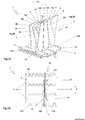
- Fig. 1 shows a conveyor 1, comprising a conveying face 2 with a side guard 20.
- the conveyor can be a modular conveyor mat, as represented here, but can also for instance be a non-modularly designed conveyor belt.
- Fig. 1 it is shown that the conveyor 1 is in a flat plane, as is the case when traversing a flat track part of a conveying path.
- Fig. 1 only a part of the conveyor 1 is represented.
- the conveyor 1 is typically of endless design, while an upper part of the conveyor is carried, with the aid of drive wheels, along a conveying track, is returned via returning wheels and is guided back via a return guide.
- the conveyor 1 is designed as a modular conveyor mat and comprises a number of modules 11 successive in conveying direction P.
- the modules 11 are each provided with a body part 12 extending transversely to the conveying direction P, with hinge loops 13A reaching forward in conveying direction and with hinge loops 13B reaching rearward in conveying direction.
- the hinge loops 13A, 13B of successive modules 11 cooperate and are coupled with the aid of hinge pins 14 not represented in the Figure.
- the conveyor 1 is provided on both long side edges 8 with a side guard 20 so that the two side guards 20 are spaced apart at a considerable intermediate distance and the largest part of the conveying face is situated between the side guards 20.
- flights may be provided (not represented in the Figure).
- a modular conveyor mat can be built up from several modules 11 transversely to the conveyor direction, for instance a series of modules without wall parts 3 which, transversely to the conveying direction P, is enclosed on the side edges 8 of the mat by edge modules with one or more wall parts 3A, 3B.
- the side guard 20 is formed having a series 10 of wall parts 3 upstanding substantially transversely to the conveying face and extending in conveying direction, indicated with double arrow P.
- two wall parts 3 overlap in conveying direction P at least partly in a fan-like manner at a top side 4 remote from the conveying face 2.
- Wall parts 3 in the series 10 mutually differ at least at their top sides 4.
- Wall parts 3 in the series 10 successive in conveying direction P mutually differ at their tops 4 in their distance with respect to a longitudinal edge 8 of the conveyor 1.
- These overlapping wall parts 3 are provided while including a slot-shaped interspace 5 with a thickness which corresponds to at least one top side 4 of a wall part 3.
- the wall parts 3 overlapping with a slot-shaped interspace 5 are not successive in conveying direction P but in each case separated by a further wall part.
- the, in each case, two wall parts 3 overlapping at the top side 4 at least partly in a fan-like manner, and including a slot-shaped interspace 5, can also be successive in conveying direction P.
- the slot width of the interspace 5 corresponds to the thickness of at least a top side 4 of the wall part 3.
- Adjacent at least one end 6, the overlapping wall parts 3 proceed with at least one side face 7 substantially parallel to a side edge 8 of the conveyor 1.
- the overlapping wall parts are each provided with two ends 6 which are connected via a substantially obliquely extending connecting piece 9.
- one other wall part 3A' from the series 10 is at least partly accommodated in the slot-shaped interspace 5.
- the overlapping wall parts 3A, 3B are arranged at different distances relative to the side edge 8 of the conveyor 1.
- the wall parts 3A,3B each form part of a subseries 10A, 10B of wall parts 3, while the subseries 10A, 10B form a side guard 20 of multiple design.
- the pitch of successive wall parts 3 is smaller than the pitch of successive modules 11.
- the interspace 5 adjacent the center 15 of the body part 12, in the conveying direction P, the interspace 5 has the largest slot width, and the side face 7 is located, in conveying direction P, adjacent the center 15 of the body part 12.
- the conveying face 2 is provided, adjacent the center of the middle part 12, at least at the location of an area located under the interspace 5, with a recess 16.
- the recess continues transversely to the conveying face 2 as a free space surrounded by the wall parts 3A, 3B.
- the overlapping wall parts 3A, 3B are integrally formed with a common carrier, which, in this exemplary embodiment, is formed by the body part of a module 11.
- the wall parts 3A, 3B are connected to the carrier via a common base and the common carrier is provided with hinge loops 13.
- all modules 11 are provided with two wall parts 3A, 3B.
- a module 11 is shown from the conveyor 1 of Fig. 1 .
- the module 11 shown is provided with at least two wall parts 3A, 3B.
- the module forms a side guard element for a conveyor mat 1, comprising a common carrier, in this case the body part 12 of the module 11', with a conveying face 2.
- the conveying face 2 is provided with two upstanding wall parts 3A, 3B, which overlap at least partly in a fan-like manner at a top side 4 remote from the conveying face 2, while including a slot-shaped interspace 5 which corresponds to the thickness of at least a top side 4 of the wall part 3.
- the wall parts 3 proceed, at least adjacent an end 6, with at least one side face 7 substantially parallel to a side edge 8' of the module 11.
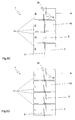
- FIG. 2 it is represented that the conveying face 2 of the conveyor 1 traverses an upward bend about an axis of rotation A1 transversely to the conveying direction P.
- the conveyor 1 performs a back flexing movement.
- the successive wall parts 3A, 3A', 3A", and 3B, 3B', 3B", respectively, in the subseries 10A, 10B overlap more than in Fig. 1 , so that the upward bend is enabled through sliding together of the wall parts.
- the side faces 7, running substantially parallel to the side edge 8 of the conveyor 1 have a relatively large slot-shaped interspace 5 adjacent the ends 6 of the overlapping wall parts 3A, 3B, a wall part 3A' successive in conveying direction P can be accommodated.
- Fig. 3 it is shown that the conveying face 2 of the conveyor 1 traverses a downward bend about an axis of rotation A2 transversely to the conveying direction P.
- the conveyor 1 performs a sprocket flexing movement.
- the wall parts 3A, 3A' successive in conveying direction overlap to a lesser extent than in the situation shown in Fig. 1 .
- a wall part 3B is present which guarantees the side guard function.
- the wall parts 3 are each provided on both ends with one side face 7 which runs substantially parallel to the side edge 8 of the conveyor 1. This needs not always be the case.
- one or both ends 6 can be provided with two side faces 7 running parallel to the side edge, or even with faces not running parallel.
- wall parts in the series can mutually differ at least at their top sides in orientation and/or distance with respect to a longitudinal edge of the conveyor.
- wall parts in the series can mutually differ at least at their top side in shape and/or size.
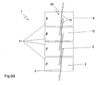
- Fig. 5A a variant embodiment is represented where the side guard 20 is built up with the aid of two types of modules 11 which alternate in conveying direction P. Both types are provided with two wall parts 3 overlapping in conveying direction at least partly in a fan-like manner while including a slot-shaped interspace 5.
- the wall parts 3 extend in their entirety substantially parallel to a side edge 8 of the conveyor 1, and are arranged each at a different distance with respect to the side edge 8 of the conveyor 1, while their orientation is the same.
- the side guard 20 is built up with a number of parallel proceeding series of wall parts 3, while per row, in conveying direction, the wall parts 3 have an interspace which is greater than a wall part 3.
- Fig. 5B a variant is shown where one of the types of modules bears only one wall part 3.
- Fig. 5C a different variant is shown, where the wall parts 3 are connected via a part that is of stepped design.
- Fig. 5D schematically, the variant embodiment of Figs. 1 - 4 is represented.
- one type of module 11 is provided, which is provided two obliquely arranged wall parts 3A.
- the wall parts 3 are placed at different distances to the side edge 8.
- Fig. 5E an embodiment is shown where two types of modules 11 are provided, each bearing one wall part 3.
- the wall parts 3 of the different types are arranged at different distances to the side edge.
- the wall parts are each provided with two ends 6 which are interconnected via a substantially obliquely extending connecting piece 9.
- the wall parts 3 are each provided with a side face 7 running substantially along the longitudinal edge.
- the side faces 7 are located in four parallel rows in conveying direction P..
- FIG. 5F an exemplary embodiment is shown where one type of module 11 is provided, while in each case, one wall part 3 is included in the same position and orientation with respect to the side edge 8.
- the wall part 3 is provided adjacent both ends 6 with a side face 7 which proceeds substantially parallel to a side edge of the conveyor.
- Wall parts successive in conveying direction overlap at least partly in a fan-like manner at a top side 4 remote from the conveying face 2 and include a slot-shaped interspace 5 which corresponds to the thickness of at least one top side of a wall part.
- the slot-shaped interspace 5 is a few times the thickness of the top side 4 of a wall part 3.
- the two ends are interconnected via a substantially obliquely extending connecting piece 9.
- the ends are interconnected via a connecting piece of substantially stepped design.
- the pitch of the wall parts is equal to the pitch of the modules, and the largest slot width is located near a hinge loop of the module. It will be clear that the exemplary embodiments represented in Fig. 5 can also be applied with a non-modular conveyor.
- the side guard element comprises a common carrier with a conveying face provided with at least two upstanding wall parts which overlap at least partly in a fan-like manner at a top side remote from the conveying surface thereby including a slot-shaped interspace which corresponds to the thickness of at least a top side of a wall part.
- the wall parts can have a common base.
- the common carrier for said sideguard for a conveyor mat can be provided with one or more hinge loops and still furthermore said common carrier can form part of a module for a modular conveyor mat, comprising a body part provided at front and rear sides extending transversely to the conveying direction with rows of hinge loops spaced apart at mutual interspaces transversely to the conveyor direction with hinge holes extending transversely to the conveying direction so that front sides and rear sides of successive modules are couplable through engagement of the hinge loops with the aid of a hinge pin extending transversely to the conveying direction, so that top faces of the coupled modules form a conveying face.
- said interspace in conveying direction can have the largest slot-width adjacent a center of the body part.
- said side surface in conveying direction can be located adjacent a center of the body part.
- the conveying face can be provided in conveying direction adjacent a center of a body part at least at the location of an area located under the interspace, with a recess, which recess preferably continues as a free space surrounded by the wall parts and/or a common base.
- overlapping wall parts can be arranged with different orientation and/or position with respect to a side edge of the module.
- a conveyor can comprise a conveying face with a side guard which is formed with a series of wall parts extending in a conveying direction and upstanding substantially transversely to the conveying face, wherein repeatedly at least two wall parts overlap in conveying direction at least partly in a fan-like manner at a top side remote from the conveying face, are arranged to include an intermediate distance which corresponds to the thickness of at least one top side of a wall part, and proceed, at least adjacent an end, with at least one side face substantially parallel to a side edge of the conveyor.
- wall parts proceed at least adjacent an end with at least one side face substantially parallel to a side edge of the conveyor, is that the wall parts can overlap when back flexing to a sufficient extent to well maintain their overlap when sprocket flexing, while, upon back flexing, the wall parts can still sufficiently slide in further.
Landscapes
- Engineering & Computer Science (AREA)
- Mechanical Engineering (AREA)
- Chain Conveyers (AREA)
- Packaging Frangible Articles (AREA)
- Structures Of Non-Positive Displacement Pumps (AREA)
- Packaging Of Machine Parts And Wound Products (AREA)
Claims (22)
- Förderer (1), umfassend eine Förderfläche (2) mit einem Seitenschutz (20), gebildet mit einer Reihe (10) von Wandteilen (3), die sich in Förderrichtung (P) erstrecken und im Wesentlichen schräg zur Förderfläche (2) aufrecht stehen, wobei sich wiederholt mindestens zwei Wandteile (3) in Förderrichtung (P) mindestens teilweise fächerartig an einer von der Förderfläche (2) entfernten Oberseite (4) überlappen, und wobei die Wandteile (3) in der Reihe (10) sich mindestens an ihren Oberseiten (4) voneinander unterscheiden, dadurch gekennzeichnet, dass die mindestens zwei überlappenden Wandteile (3) angeordnet sind, um einen schlitzförmigen Zwischenraum (5) einzuschließen, der einer Dicke von mindestens einer Oberseite (4) eines Wandteils (3) entspricht.
- Förderer nach Anspruch 1, wobei Wandteile (3) in der Reihe (10) sich mindestens an ihren Oberseiten (4) in Ausrichtung und/oder Abstand in Bezug auf eine Längskante (8) des Förderers voneinander unterscheiden.
- Förderer nach Anspruch 1 oder 2, wobei Wandteile (3) in der Reihe (10) sich mindestens an ihren Oberseiten (4) in Form und/oder Größe voneinander unterscheiden.
- Förderer nach einem der vorhergehenden Ansprüche, wobei Wandteile (3) in der Reihe (10), in Förderrichtung (P) aufeinander folgend, sich von einander an ihren Oberseiten (4) unterscheiden.
- Förderer nach Anspruch 1, wobei, angrenzend an ein Ende (6), die überlappenden Wandteile (3) mindestens eine Seitenfläche (7) haben, die im Wesentlichen parallel zu einer Seitenkante (8) des Förderers (1) verläuft.
- Förderer nach einem der vorhergehenden Ansprüche, wobei die überlappenden Wandteile (3), gesehen in Förderrichtung (P), jeweils mit zwei Enden (6) versehen sind, die über ein im Wesentlichen schräg verlaufendes Verbindungsstück (9) verbunden sind.
- Förderer nach einem der vorhergehenden Ansprüche, wobei, gesehen in Förderrichtung (P), die aufrechten Wände (3) jeweils mit zwei Enden (6) versehen sind, die über ein Verbindungsstück (9) von im Wesentlichen stufenförmigem Design verbunden sind.
- Förderer nach einem der vorhergehenden Ansprüche, wobei eines oder mehrere der Wandteile (3) der Reihe (10) mindestens teilweise in dem schlitzförmigen Zwischenraum (5) aufgenommen werden können.
- Förderer nach einem der vorhergehenden Ansprüche, wobei eines oder mehrere andere Wandteile (3) der Serie (10) mindestens teilweise in den schlitzförmigen Zwischenräumen (5) aufgenommen sind.
- Förderer nach einem der vorhergehenden Ansprüche, wobei die überlappenden Wandteile (3) mit unterschiedlicher Orientierung und/oder unterschiedlichem Abstand in Bezug auf eine Seitenkante (8) des Förderers (1) angeordnet sind.
- Förderer nach einem der vorhergehenden Ansprüche, wobei die Reihe (10) mit verschiedenen Typen von Wandteilen (3) gebildet ist.
- Förderer nach einem der vorhergehenden Ansprüche, wobei die Wandteile (3) jeweils einen Teil einer Teilreihe (10A, 10B) von Wandteilen (3) bilden, wobei die Teilreihen zusammen einen Seitenschutz (20) vielfältiger Art bilden.
- Förderer nach einem der vorhergehenden Ansprüche, umfassend eine Anzahl von Modulen (11), aufeinander folgend in Förderrichtung (P), jeweils versehen mit einem Körperteil (11), das quer zur Förderrichtung (P) verläuft, mit Scharnierschlingen (13A, 13B), die vorwärts und rückwärts in Förderrichtung (P) reichen, wobei die Scharnierschlingen (13A, 13B) von aufeinander folgenden Modulen (11) zusammenwirken und mithilfe von Scharnierstiften (14) gekoppelt sind.
- Förderer nach Anspruch 13, wobei in Förderrichtung (P) der Abstand aufeinander folgender Wandteile (3) kleiner ist als der Abstand aufeinander folgender Module (11).
- Förderer nach Anspruch 13 oder 14, wobei in Förderrichtung (P) der Zwischenraum (5) die größte Schlitzbreite angrenzend an ein Zentrum (5) eines Körperteils (12) hat.
- Förderer nach einem der Ansprüche 13-15, wobei in Förderrichtung (P) die Seitenfläche (7) sich angrenzend an ein Zentrum (15) eines Körperteils (12) befindet.
- Förderer nach einem der Ansprüche 13-16, wobei die Förderfläche (2) angrenzend an ein Zentrum (15) eines Körperteils (12) und mindestens an der Stelle eines Bereichs unter dem Zwischenraum (5) bereitgestellt ist, mit einer Aussparung (16), die sich vorzugsweise als freier Raum, umgeben von den Wandteilen (3) und/oder einer gemeinsamen Basis fortsetzt.
- Förderer nach einem der vorhergehenden Ansprüche, wobei die überlappenden Wandteile (3) integral mit einem gemeinsamen Träger gebildet sind.
- Förderer nach Anspruch 18, wobei die Wandteile (3) über eine gemeinsame Basis (17) mit dem Träger verbunden sind.
- Förderer nach Anspruch 13 und Ansprüchen 18 oder 19, wobei der gemeinsame Träger mit einer oder mehreren Scharnierschlingen (13A, 13B) versehen ist.
- Förderer nach Anspruch 13 und einem der Ansprüche 18-20, wobei der gemeinsame Träger einen Teil eines Modus (11) bildet.
- Förderer nach einem der Ansprüche 13-21, wobei mindestens eine Anzahl von Modulen (11) mit mindestens zwei Wandteilen (3) versehen sind.
Applications Claiming Priority (2)
| Application Number | Priority Date | Filing Date | Title |
|---|---|---|---|
| NL2001205A NL2001205C2 (nl) | 2008-01-21 | 2008-01-21 | Transporteur voorzien van zijgeleiding, alsmede zijgeleidingselement. |
| PCT/NL2009/050021 WO2009093897A2 (en) | 2008-01-21 | 2009-01-19 | Conveyor provided with side guard, and side guard element |
Publications (2)
| Publication Number | Publication Date |
|---|---|
| EP2242709A2 EP2242709A2 (de) | 2010-10-27 |
| EP2242709B1 true EP2242709B1 (de) | 2012-08-01 |
Family
ID=39689396
Family Applications (1)
| Application Number | Title | Priority Date | Filing Date |
|---|---|---|---|
| EP09704605A Active EP2242709B1 (de) | 2008-01-21 | 2009-01-19 | Förderband mit seitenschutz und seitenschutzelement |
Country Status (7)
| Country | Link |
|---|---|
| US (1) | US8371436B2 (de) |
| EP (1) | EP2242709B1 (de) |
| CN (1) | CN101925524B (de) |
| AU (1) | AU2009206818B2 (de) |
| MX (1) | MX2010007933A (de) |
| NL (1) | NL2001205C2 (de) |
| WO (1) | WO2009093897A2 (de) |
Families Citing this family (7)
| Publication number | Priority date | Publication date | Assignee | Title |
|---|---|---|---|---|
| CN103057905B (zh) * | 2013-01-25 | 2015-11-18 | 世林(漯河)冶金设备有限公司 | 一种链带托盘装置 |
| US9156620B2 (en) * | 2013-03-14 | 2015-10-13 | Illinois Tool Works Inc. | Conveyor belt and platform for conveyor belt |
| CN104261053A (zh) * | 2014-08-14 | 2015-01-07 | 天地科技股份有限公司 | 一种板式快速定量输送机的承载板 |
| US10099859B2 (en) | 2015-04-15 | 2018-10-16 | Laitram, L.L.C. | Self-stacking spiral modular plastic conveyor belt with intermediate support |
| US10155625B1 (en) | 2015-09-01 | 2018-12-18 | Laitram, L.L.C. | Conveyor belts and modules with twist-lock accessories |
| US11840401B2 (en) * | 2021-07-21 | 2023-12-12 | Forjas Bolivar S.A.S. | Plate chain with self-supported mechanism |
| CN115924352B (zh) * | 2023-02-13 | 2023-10-10 | 广东源憬健康科技有限公司 | 垃圾自动处理系统 |
Family Cites Families (13)
| Publication number | Priority date | Publication date | Assignee | Title |
|---|---|---|---|---|
| GB1367156A (en) * | 1971-11-15 | 1974-09-18 | Laitram Corp | Modlue for constructing linked structures |
| SE422773B (sv) * | 1978-09-15 | 1982-03-29 | Andersson Kurt Goeran | Godstransporterande bana bestaende av vridbart till varandra festade lenkar |
| US4556142A (en) * | 1983-01-12 | 1985-12-03 | The Laitram Corporation | Lightweight modular conveyor belt |
| DE3571020D1 (en) * | 1984-08-20 | 1989-07-20 | Laitram Corp | Conveyor belt having insertable & selectable conveying members |
| US4840269A (en) * | 1988-03-28 | 1989-06-20 | Rexnord Inc. | Apron type conveyor |
| JPH0543026A (ja) * | 1989-09-22 | 1993-02-23 | Eretsutsu:Kk | コンベヤ装置 |
| US6840371B2 (en) * | 2001-06-29 | 2005-01-11 | Rexnord Industries, Inc. | Link having a twisted side guard |
| US6766901B2 (en) * | 2001-07-19 | 2004-07-27 | Habasit Ag | Snap-on side guards |
| US6695128B2 (en) * | 2002-07-18 | 2004-02-24 | Kvp Falcon Plastic Belting, Inc. | Stacked spiral modular plastic conveyor belt system |
| US6811021B1 (en) * | 2003-11-06 | 2004-11-02 | Laitram, L.L.C. | Plastic conveyor belt modules with unitary sideguards |
| US7270231B2 (en) | 2005-05-26 | 2007-09-18 | Heber Gerald J | Self-stacking spiral conveyor belt |
| US7556145B2 (en) * | 2006-12-08 | 2009-07-07 | Habasit Ag | Gapless side guard |
| US7500555B1 (en) * | 2008-06-20 | 2009-03-10 | Miaw Yeou Metal Industry Co., Ltd | Link plate for a metal waste conveyer |
-
2008
- 2008-01-21 NL NL2001205A patent/NL2001205C2/nl not_active IP Right Cessation
-
2009
- 2009-01-19 US US12/863,783 patent/US8371436B2/en active Active
- 2009-01-19 MX MX2010007933A patent/MX2010007933A/es active IP Right Grant
- 2009-01-19 CN CN2009801026650A patent/CN101925524B/zh active Active
- 2009-01-19 EP EP09704605A patent/EP2242709B1/de active Active
- 2009-01-19 WO PCT/NL2009/050021 patent/WO2009093897A2/en active Application Filing
- 2009-01-19 AU AU2009206818A patent/AU2009206818B2/en active Active
Also Published As
| Publication number | Publication date |
|---|---|
| US20110000767A1 (en) | 2011-01-06 |
| CN101925524B (zh) | 2013-06-05 |
| EP2242709A2 (de) | 2010-10-27 |
| AU2009206818A1 (en) | 2009-07-30 |
| US8371436B2 (en) | 2013-02-12 |
| WO2009093897A2 (en) | 2009-07-30 |
| CN101925524A (zh) | 2010-12-22 |
| AU2009206818B2 (en) | 2013-09-19 |
| NL2001205C2 (nl) | 2009-07-22 |
| MX2010007933A (es) | 2010-11-30 |
| WO2009093897A3 (en) | 2009-09-24 |
Similar Documents
| Publication | Publication Date | Title |
|---|---|---|
| EP2242709B1 (de) | Förderband mit seitenschutz und seitenschutzelement | |
| EP1687221B1 (de) | Kunststoffförderbandmodule mit seitenschutz | |
| US6695128B2 (en) | Stacked spiral modular plastic conveyor belt system | |
| US6382404B1 (en) | Corrugated flight module | |
| US6766901B2 (en) | Snap-on side guards | |
| EP1890950B1 (de) | Kunststoffförderbänder und module mit seitenkanälen | |
| JP2711406B2 (ja) | 駆動用連結部を有するモジュール及び該モジュールより組立てられたコンベヤベルト | |
| EP1068139B1 (de) | Fördermatte | |
| US6644466B2 (en) | Platform-top radius belt and modules | |
| EP2655223A1 (de) | Verbessertes laterales plattenelement für eine verbindung in einem selbststapelnden endlosen förderband | |
| US8220620B2 (en) | Load-carrying conveyor chain | |
| US20140008187A1 (en) | Modular conveyor mat and module therefor | |
| EP3233674B1 (de) | Förderbandmodul mit geformter bodenfläche | |
| WO2000013993A1 (en) | Conveyor mat built up from plastic modules, and module for such conveyor mat | |
| CN113272235B (zh) | 双轴模块化带和输送机 | |
| US20230137570A1 (en) | Modular conveyor mat and module therefor | |
| EP3253694B1 (de) | Förderbandmodul mit gestuftem scharnierdurchgang |
Legal Events
| Date | Code | Title | Description |
|---|---|---|---|
| PUAI | Public reference made under article 153(3) epc to a published international application that has entered the european phase |
Free format text: ORIGINAL CODE: 0009012 |
|
| 17P | Request for examination filed |
Effective date: 20100818 |
|
| AK | Designated contracting states |
Kind code of ref document: A2 Designated state(s): AT BE BG CH CY CZ DE DK EE ES FI FR GB GR HR HU IE IS IT LI LT LU LV MC MK MT NL NO PL PT RO SE SI SK TR |
|
| AX | Request for extension of the european patent |
Extension state: AL BA RS |
|
| DAX | Request for extension of the european patent (deleted) | ||
| GRAP | Despatch of communication of intention to grant a patent |
Free format text: ORIGINAL CODE: EPIDOSNIGR1 |
|
| GRAS | Grant fee paid |
Free format text: ORIGINAL CODE: EPIDOSNIGR3 |
|
| GRAA | (expected) grant |
Free format text: ORIGINAL CODE: 0009210 |
|
| AK | Designated contracting states |
Kind code of ref document: B1 Designated state(s): AT BE BG CH CY CZ DE DK EE ES FI FR GB GR HR HU IE IS IT LI LT LU LV MC MK MT NL NO PL PT RO SE SI SK TR |
|
| REG | Reference to a national code |
Ref country code: GB Ref legal event code: FG4D |
|
| REG | Reference to a national code |
Ref country code: AT Ref legal event code: REF Ref document number: 568546 Country of ref document: AT Kind code of ref document: T Effective date: 20120815 Ref country code: CH Ref legal event code: EP |
|
| REG | Reference to a national code |
Ref country code: IE Ref legal event code: FG4D |
|
| REG | Reference to a national code |
Ref country code: DE Ref legal event code: R096 Ref document number: 602009008649 Country of ref document: DE Effective date: 20120927 |
|
| REG | Reference to a national code |
Ref country code: NL Ref legal event code: T3 |
|
| REG | Reference to a national code |
Ref country code: AT Ref legal event code: MK05 Ref document number: 568546 Country of ref document: AT Kind code of ref document: T Effective date: 20120801 |
|
| REG | Reference to a national code |
Ref country code: LT Ref legal event code: MG4D Effective date: 20120801 |
|
| PG25 | Lapsed in a contracting state [announced via postgrant information from national office to epo] |
Ref country code: CY Free format text: LAPSE BECAUSE OF FAILURE TO SUBMIT A TRANSLATION OF THE DESCRIPTION OR TO PAY THE FEE WITHIN THE PRESCRIBED TIME-LIMIT Effective date: 20120801 Ref country code: NO Free format text: LAPSE BECAUSE OF FAILURE TO SUBMIT A TRANSLATION OF THE DESCRIPTION OR TO PAY THE FEE WITHIN THE PRESCRIBED TIME-LIMIT Effective date: 20121101 Ref country code: LT Free format text: LAPSE BECAUSE OF FAILURE TO SUBMIT A TRANSLATION OF THE DESCRIPTION OR TO PAY THE FEE WITHIN THE PRESCRIBED TIME-LIMIT Effective date: 20120801 Ref country code: IS Free format text: LAPSE BECAUSE OF FAILURE TO SUBMIT A TRANSLATION OF THE DESCRIPTION OR TO PAY THE FEE WITHIN THE PRESCRIBED TIME-LIMIT Effective date: 20121201 Ref country code: AT Free format text: LAPSE BECAUSE OF FAILURE TO SUBMIT A TRANSLATION OF THE DESCRIPTION OR TO PAY THE FEE WITHIN THE PRESCRIBED TIME-LIMIT Effective date: 20120801 Ref country code: FI Free format text: LAPSE BECAUSE OF FAILURE TO SUBMIT A TRANSLATION OF THE DESCRIPTION OR TO PAY THE FEE WITHIN THE PRESCRIBED TIME-LIMIT Effective date: 20120801 Ref country code: HR Free format text: LAPSE BECAUSE OF FAILURE TO SUBMIT A TRANSLATION OF THE DESCRIPTION OR TO PAY THE FEE WITHIN THE PRESCRIBED TIME-LIMIT Effective date: 20120801 |
|
| PG25 | Lapsed in a contracting state [announced via postgrant information from national office to epo] |
Ref country code: GR Free format text: LAPSE BECAUSE OF FAILURE TO SUBMIT A TRANSLATION OF THE DESCRIPTION OR TO PAY THE FEE WITHIN THE PRESCRIBED TIME-LIMIT Effective date: 20121102 Ref country code: PT Free format text: LAPSE BECAUSE OF FAILURE TO SUBMIT A TRANSLATION OF THE DESCRIPTION OR TO PAY THE FEE WITHIN THE PRESCRIBED TIME-LIMIT Effective date: 20121203 Ref country code: PL Free format text: LAPSE BECAUSE OF FAILURE TO SUBMIT A TRANSLATION OF THE DESCRIPTION OR TO PAY THE FEE WITHIN THE PRESCRIBED TIME-LIMIT Effective date: 20120801 Ref country code: LV Free format text: LAPSE BECAUSE OF FAILURE TO SUBMIT A TRANSLATION OF THE DESCRIPTION OR TO PAY THE FEE WITHIN THE PRESCRIBED TIME-LIMIT Effective date: 20120801 Ref country code: SE Free format text: LAPSE BECAUSE OF FAILURE TO SUBMIT A TRANSLATION OF THE DESCRIPTION OR TO PAY THE FEE WITHIN THE PRESCRIBED TIME-LIMIT Effective date: 20120801 Ref country code: SI Free format text: LAPSE BECAUSE OF FAILURE TO SUBMIT A TRANSLATION OF THE DESCRIPTION OR TO PAY THE FEE WITHIN THE PRESCRIBED TIME-LIMIT Effective date: 20120801 Ref country code: BE Free format text: LAPSE BECAUSE OF FAILURE TO SUBMIT A TRANSLATION OF THE DESCRIPTION OR TO PAY THE FEE WITHIN THE PRESCRIBED TIME-LIMIT Effective date: 20120801 |
|
| PG25 | Lapsed in a contracting state [announced via postgrant information from national office to epo] |
Ref country code: DK Free format text: LAPSE BECAUSE OF FAILURE TO SUBMIT A TRANSLATION OF THE DESCRIPTION OR TO PAY THE FEE WITHIN THE PRESCRIBED TIME-LIMIT Effective date: 20120801 Ref country code: CZ Free format text: LAPSE BECAUSE OF FAILURE TO SUBMIT A TRANSLATION OF THE DESCRIPTION OR TO PAY THE FEE WITHIN THE PRESCRIBED TIME-LIMIT Effective date: 20120801 Ref country code: EE Free format text: LAPSE BECAUSE OF FAILURE TO SUBMIT A TRANSLATION OF THE DESCRIPTION OR TO PAY THE FEE WITHIN THE PRESCRIBED TIME-LIMIT Effective date: 20120801 Ref country code: ES Free format text: LAPSE BECAUSE OF FAILURE TO SUBMIT A TRANSLATION OF THE DESCRIPTION OR TO PAY THE FEE WITHIN THE PRESCRIBED TIME-LIMIT Effective date: 20121112 Ref country code: RO Free format text: LAPSE BECAUSE OF FAILURE TO SUBMIT A TRANSLATION OF THE DESCRIPTION OR TO PAY THE FEE WITHIN THE PRESCRIBED TIME-LIMIT Effective date: 20120801 |
|
| PG25 | Lapsed in a contracting state [announced via postgrant information from national office to epo] |
Ref country code: SK Free format text: LAPSE BECAUSE OF FAILURE TO SUBMIT A TRANSLATION OF THE DESCRIPTION OR TO PAY THE FEE WITHIN THE PRESCRIBED TIME-LIMIT Effective date: 20120801 |
|
| PLBE | No opposition filed within time limit |
Free format text: ORIGINAL CODE: 0009261 |
|
| STAA | Information on the status of an ep patent application or granted ep patent |
Free format text: STATUS: NO OPPOSITION FILED WITHIN TIME LIMIT |
|
| 26N | No opposition filed |
Effective date: 20130503 |
|
| PG25 | Lapsed in a contracting state [announced via postgrant information from national office to epo] |
Ref country code: BG Free format text: LAPSE BECAUSE OF FAILURE TO SUBMIT A TRANSLATION OF THE DESCRIPTION OR TO PAY THE FEE WITHIN THE PRESCRIBED TIME-LIMIT Effective date: 20121101 |
|
| REG | Reference to a national code |
Ref country code: DE Ref legal event code: R097 Ref document number: 602009008649 Country of ref document: DE Effective date: 20130503 |
|
| PG25 | Lapsed in a contracting state [announced via postgrant information from national office to epo] |
Ref country code: MC Free format text: LAPSE BECAUSE OF NON-PAYMENT OF DUE FEES Effective date: 20130131 |
|
| REG | Reference to a national code |
Ref country code: CH Ref legal event code: PL |
|
| GBPC | Gb: european patent ceased through non-payment of renewal fee |
Effective date: 20130119 |
|
| REG | Reference to a national code |
Ref country code: IE Ref legal event code: MM4A |
|
| REG | Reference to a national code |
Ref country code: FR Ref legal event code: ST Effective date: 20130930 |
|
| PG25 | Lapsed in a contracting state [announced via postgrant information from national office to epo] |
Ref country code: CH Free format text: LAPSE BECAUSE OF NON-PAYMENT OF DUE FEES Effective date: 20130131 Ref country code: LI Free format text: LAPSE BECAUSE OF NON-PAYMENT OF DUE FEES Effective date: 20130131 |
|
| PG25 | Lapsed in a contracting state [announced via postgrant information from national office to epo] |
Ref country code: FR Free format text: LAPSE BECAUSE OF NON-PAYMENT OF DUE FEES Effective date: 20130131 Ref country code: GB Free format text: LAPSE BECAUSE OF NON-PAYMENT OF DUE FEES Effective date: 20130119 |
|
| PG25 | Lapsed in a contracting state [announced via postgrant information from national office to epo] |
Ref country code: IE Free format text: LAPSE BECAUSE OF NON-PAYMENT OF DUE FEES Effective date: 20130119 |
|
| PG25 | Lapsed in a contracting state [announced via postgrant information from national office to epo] |
Ref country code: MT Free format text: LAPSE BECAUSE OF FAILURE TO SUBMIT A TRANSLATION OF THE DESCRIPTION OR TO PAY THE FEE WITHIN THE PRESCRIBED TIME-LIMIT Effective date: 20120801 |
|
| PG25 | Lapsed in a contracting state [announced via postgrant information from national office to epo] |
Ref country code: TR Free format text: LAPSE BECAUSE OF FAILURE TO SUBMIT A TRANSLATION OF THE DESCRIPTION OR TO PAY THE FEE WITHIN THE PRESCRIBED TIME-LIMIT Effective date: 20120801 |
|
| PG25 | Lapsed in a contracting state [announced via postgrant information from national office to epo] |
Ref country code: HU Free format text: LAPSE BECAUSE OF FAILURE TO SUBMIT A TRANSLATION OF THE DESCRIPTION OR TO PAY THE FEE WITHIN THE PRESCRIBED TIME-LIMIT; INVALID AB INITIO Effective date: 20090119 Ref country code: MK Free format text: LAPSE BECAUSE OF FAILURE TO SUBMIT A TRANSLATION OF THE DESCRIPTION OR TO PAY THE FEE WITHIN THE PRESCRIBED TIME-LIMIT Effective date: 20120801 Ref country code: LU Free format text: LAPSE BECAUSE OF NON-PAYMENT OF DUE FEES Effective date: 20130119 |
|
| P01 | Opt-out of the competence of the unified patent court (upc) registered |
Effective date: 20230522 |
|
| PGFP | Annual fee paid to national office [announced via postgrant information from national office to epo] |
Ref country code: NL Payment date: 20231212 Year of fee payment: 16 |
|
| PGFP | Annual fee paid to national office [announced via postgrant information from national office to epo] |
Ref country code: DE Payment date: 20240119 Year of fee payment: 16 |
|
| PGFP | Annual fee paid to national office [announced via postgrant information from national office to epo] |
Ref country code: IT Payment date: 20240129 Year of fee payment: 16 |