EP2242676B1 - Arrangement of a rolling stabilization system and of a steering system on a motor vehicle - Google Patents
Arrangement of a rolling stabilization system and of a steering system on a motor vehicle Download PDFInfo
- Publication number
- EP2242676B1 EP2242676B1 EP09712134.7A EP09712134A EP2242676B1 EP 2242676 B1 EP2242676 B1 EP 2242676B1 EP 09712134 A EP09712134 A EP 09712134A EP 2242676 B1 EP2242676 B1 EP 2242676B1
- Authority
- EP
- European Patent Office
- Prior art keywords
- motor
- steering
- vehicle
- transmission
- motors
- Prior art date
- Legal status (The legal status is an assumption and is not a legal conclusion. Google has not performed a legal analysis and makes no representation as to the accuracy of the status listed.)
- Active
Links
Images
Classifications
-
- B—PERFORMING OPERATIONS; TRANSPORTING
- B62—LAND VEHICLES FOR TRAVELLING OTHERWISE THAN ON RAILS
- B62D—MOTOR VEHICLES; TRAILERS
- B62D5/00—Power-assisted or power-driven steering
- B62D5/04—Power-assisted or power-driven steering electrical, e.g. using an electric servo-motor connected to, or forming part of, the steering gear
- B62D5/0421—Electric motor acting on or near steering gear
- B62D5/0424—Electric motor acting on or near steering gear the axes of motor and final driven element of steering gear, e.g. rack, being parallel
-
- B—PERFORMING OPERATIONS; TRANSPORTING
- B60—VEHICLES IN GENERAL
- B60G—VEHICLE SUSPENSION ARRANGEMENTS
- B60G21/00—Interconnection systems for two or more resiliently-suspended wheels, e.g. for stabilising a vehicle body with respect to acceleration, deceleration or centrifugal forces
- B60G21/02—Interconnection systems for two or more resiliently-suspended wheels, e.g. for stabilising a vehicle body with respect to acceleration, deceleration or centrifugal forces permanently interconnected
- B60G21/04—Interconnection systems for two or more resiliently-suspended wheels, e.g. for stabilising a vehicle body with respect to acceleration, deceleration or centrifugal forces permanently interconnected mechanically
- B60G21/05—Interconnection systems for two or more resiliently-suspended wheels, e.g. for stabilising a vehicle body with respect to acceleration, deceleration or centrifugal forces permanently interconnected mechanically between wheels on the same axle but on different sides of the vehicle, i.e. the left and right wheel suspensions being interconnected
- B60G21/055—Stabiliser bars
- B60G21/0551—Mounting means therefor
- B60G21/0553—Mounting means therefor adjustable
- B60G21/0555—Mounting means therefor adjustable including an actuator inducing vehicle roll
-
- B—PERFORMING OPERATIONS; TRANSPORTING
- B62—LAND VEHICLES FOR TRAVELLING OTHERWISE THAN ON RAILS
- B62D—MOTOR VEHICLES; TRAILERS
- B62D5/00—Power-assisted or power-driven steering
- B62D5/04—Power-assisted or power-driven steering electrical, e.g. using an electric servo-motor connected to, or forming part of, the steering gear
-
- B—PERFORMING OPERATIONS; TRANSPORTING
- B60—VEHICLES IN GENERAL
- B60G—VEHICLE SUSPENSION ARRANGEMENTS
- B60G2200/00—Indexing codes relating to suspension types
- B60G2200/40—Indexing codes relating to the wheels in the suspensions
- B60G2200/44—Indexing codes relating to the wheels in the suspensions steerable
-
- B—PERFORMING OPERATIONS; TRANSPORTING
- B60—VEHICLES IN GENERAL
- B60G—VEHICLE SUSPENSION ARRANGEMENTS
- B60G2202/00—Indexing codes relating to the type of spring, damper or actuator
- B60G2202/40—Type of actuator
- B60G2202/42—Electric actuator
-
- B—PERFORMING OPERATIONS; TRANSPORTING
- B60—VEHICLES IN GENERAL
- B60G—VEHICLE SUSPENSION ARRANGEMENTS
- B60G2204/00—Indexing codes related to suspensions per se or to auxiliary parts
- B60G2204/10—Mounting of suspension elements
- B60G2204/20—Mounting of accessories, e.g. pump, compressor
Definitions
- the invention relates to the arrangement of a roll stabilization system with shared anti-roll bar and a steering system on a two-lane motor vehicle, wherein a transmission of the roll stabilization system is arranged substantially coaxially between the two mutually rotatable halves of the anti-roll bar and a motor for initiating a stabilizing moment laterally of this transmission and anti-roll bar, and wherein the steering system, in addition to a steering gear, with which ultimately acting on the steerable vehicle wheels steering lever are displaced substantially in the vehicle transverse direction, a side of the steering gear and a displacement axis described by the displaceable steering lever arranged motor to initiate such a shift supporting or inducing Moments has.
- the technical environment is for example on the DE 102 33 499 A1 as well as on the DE 101 42 388 A1 and the DE 10 2006 001 821 A1 directed.
- a steering assist motor for example, on a rack-and-pinion steering gear in the vehicle transverse direction extending rack, at the ends of which in a known manner ultimately acting on the steerable wheels track lever or tie rods connect, be arranged.
- the transmission of the torque from the respective engine, whose axis of rotation preferably extends in the vehicle transverse direction, to the respective transmission, ie to the transmission "within" the divided anti-roll bar or for example.
- Rack and pinion steering gear via a gear transmission or an endless traction mechanism.
- the proposed arrangement is characterized by the greatest possible compactness, i.
- the available free space can be optimally used in this way. It is particularly favorable that this entire arrangement in the so-called right-hand drive vehicles, in which a steering request of the driver from his steering wheel to the steering gear transmitting steering spindle in the right half of the vehicle, simply (with respect to the vehicle longitudinal axis) mirror-symmetrical to the so-called Left-hand drive vehicles can be arranged.
- a structurally identical motor can be used for the steering system and for the roll stabilization system, in particular if these are electric motors whose axes of rotation preferably run in the vehicle transverse direction and substantially coincide.
- the arrangement within a preferably a pre-assembly forming Achschts shows advantages in assembling the vehicle, wherein in advantageous developments, the said engine or engine-transmission units, by an assembly of said engine, the transmission of each system (roll stabilization system, steering system) and a Between transmission for transmitting the torque from the engine to the so-called.
- System gearbox are formed, the stiffening of the axle beam, for example.
- a vehicle crash can serve by at least one suitable support (according to claims 4, 5) is provided ,
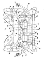
- the reference numeral 1 denotes in its entirety a so-called. Achs nave for the front axle of a car, which consists essentially of two on both sides of the vehicle in the longitudinal direction extending longitudinal beams 1a and a front cross member 1b and a rear cross member 1c, between the two Longitudinal beams 1a are supported.
- the central longitudinal axis of the vehicle is designated by the reference numeral 2 and the direction of travel of the vehicle is represented by the arrow FR.
- Behind the front cross member 1 b are symmetrically to the longitudinal axis 2 still supported recordings 1 d for engine mounts between the cross member 1 c and the respective longitudinal member 1a, the latter being cut off in Figure and therefore not fully visible.
- a stabilizer bar 4 provided on the left side and on the right side a pendulum support 3 is supported on one of said wheel guide members or on a basically known so-called. Swivel bearing of the respective wheel.
- This anti-roll bar 4 is divided centrally and thus consists of a right-side and a left-side stabilizer half 4a and 4b, which are connected to each other via a gear 5a, that these two in bearing points 6 rotatably mounted on the axle 1 stabilizer halves 4a, 4b with their sections extending on a common transverse axis 4c can be rotated relative to each other about this transverse axis 4c by a certain angular amount.
- This can be counteracted in a manner known in principle a rolling of supported on the said wheels vehicle body, wherein the corresponding torque, which is referred to as a stabilizing moment and with which the stabilizer halves 4a, 4b are rotated against each other, from a motor 5b in said transmission 5a is initiated.
- the split anti-roll bar 4 described so far forms together with the gear 5a and the motor 5b, which is an electric motor, a so-called roll stabilization system 5.
- the motor 5b of the roll stabilization system 5 is laterally inclined.
- Axis 4c of the anti-roll bar 4 and the transmission 5a arranged and it is for transmitting the torque from the motor 5b in the transmission 5a, a suitable intermediate gear 5e, for example.
- a gear transmission or an endless traction mechanism provided.
- lateral does not mean that the motor 5b is arranged laterally next to the gearbox 5a, but is intended to express that the axis of rotation of the motor 5b and the input or output axis of rotation of the gearbox 5a do not coincide ,
- the wheels mentioned above are the front wheels of the vehicle, they are steerable by means of a steering system 7, it being expressly pointed out at this point that a corresponding (inventive) arrangement of a roll stabilization system 5 and a steering system 7 described briefly below also for the rear wheels of a two-lane vehicle, that can be provided on the rear axle, if the rear wheels are at least slightly steerable.
- a servo steering system with support torque which can be introduced into the steering gear is described below, this invention can also be applied to a steer-by-wire system in which only a motor torque is introduced.
- the steering system 7 (the front axle) is designed as a basically known rack and pinion steering, i. there is a rack-and-pinion steering gear 7a extending in the vehicle transverse direction, in which a steering angle desired by the driver of the vehicle can be introduced via a steering spindle connection 7c via a steering spindle (not shown) and into which also an engine, which is likewise designed as an electric motor 7b a support moment can be initiated.
- a steering angle introduced via the said steering spindle and / or an assisting torque introduced via the motor 7b causes or brings about that track lever or tie rods which are not shown on both sides of the rack and pinion steering gear 7a to the ends of its rack in a known manner the other end are ultimately connected to the already mentioned pivot bearing of the respective wheel, be moved with their rack pivot points in the vehicle transverse direction.
- the corresponding so-called displacement axis 7d of the tracking levers or toggle linkage points to the rack-and-pinion steering gear 7a is known to be defined by the longitudinal direction of the rack of the rack-and-pinion steering gear 7a and, as can be seen, is the motor 7b of the steering system 7 arranged laterally from the displacement axis 7d and the side of the rack-and-pinion steering gear 7a, in which case the word "laterally” can also stand for the term “laterally beside”.
- a suitable intermediate gear 7e for example. In the form of a gear transmission, is provided.
- the two motors 5b, 7b namely the electric motor 5b of the roll stabilization system 5 and the electric motor 7b of the steering system 7 so arranged in the vehicle transverse direction one behind the other, that their Rotational axes substantially coincide, that are substantially on a lying in the vehicle transverse direction in a direction parallel to the road surface horizontal plane perpendicular to the longitudinal axis 2 of the vehicle extending common motor rotation axis 8.
- the rack-and-pinion steering gear 7a carries the associated motor 7b and is fastened at each end via a support point 9 on the left and on the right front corner region of the front axle support 1, wherein in the figure, only one of these support points 9 is visible, as the other, with respect the longitudinal axis 2 mirror-symmetrical support point is located in this view behind the engine 5b.
- the steering gear 7a is supported together with the associated motor 7b provided on the rear cross member 1 c Anflanschaugen on this cross member 1c.
- the steering system 7 contributes to the stiffening of the axle beam 1 at.
- the motor 5b of the roll stabilization system 5 and / or its gear 5a can be supported, on the one hand, between a corner region of the axle beam 1 and, on the other hand, a transverse strut 1b or 1c of the axle beam 1, as shown in the appended FIGURE.
Description
Die Erfindung betrifft die Anordnung eines Wankstabilisierungssystems mit geteiltem Querstabilisator sowie eines Lenksystems an einem zweispurigen Kraftfahrzeug, wobei ein Getriebe des Wankstabilisierungssystems im wesentlichen koaxial zwischen den beiden gegeneinander verdrehbaren Hälften des Querstabilisators und ein Motor zum Einleiten eines Stabilisierungsmomentes seitlich dieses Getriebes und Querstabilisators angeordnet ist, und wobei das Lenksystem neben einem Lenkgetriebe, mit welchem letztlich auf die lenkbaren Fahrzeug-Räder einwirkende Spurhebel im wesentlichen in Fahrzeug-Querrichtung verlagerbar sind, einen seitlich des Lenkgetriebes und einer durch die verlagerbaren Spurhebel beschriebenen Verlagerungsachse angeordneten Motor zur Einleitung eines eine solche Verlagerung unterstützenden oder veranlassenden Moments aufweist. Zum technischen Umfeld wird beispielshalber auf die
Neben der derzeit bei der Anmelderin in Serienproduktion gewählten Anordnung eines Stell-Motors eines Wankstabilisierungssystems koaxial zum geteilten Querstabilisator ist die Anordnung dieses Stell-Motors abseits des Querstablisators bereits grundsätzlich bekannt. In vergleichbarer Weise kann auch ein Lenkunterstützungs-Motor bspw. an einem Zahnstangen-Lenkgetriebe sich in Fahrzeug-Querrichtung erstreckender Zahnstange, an deren Enden sich in bekannter Weise letztlich auf die lenkbaren Räder einwirkende Spurhebel oder Spurstangen anschließen, angeordnet sein. Dabei kann die Übertragung des Drehmoments vom jeweiligen Motor, dessen Rotationsachse vorzugsweise in Fahrzeug-Querrichtung verläuft, zum jeweiligen Getriebe, d.h. zum Getriebe "innerhalb" des geteilten Querstabilisators bzw. zum bspw. Zahnstangen-Lenkgetriebe über ein Zahnradgetriebe oder ein endloses Zugmittelgetriebe erfolgen.In addition to the currently selected in the applicant in mass production arrangement of a servo motor of a roll stabilization system coaxial with the divided anti-roll bar the arrangement of this servo motor away from the cross-starter is already known in principle. In a comparable manner, a steering assist motor, for example, on a rack-and-pinion steering gear in the vehicle transverse direction extending rack, at the ends of which in a known manner ultimately acting on the steerable wheels track lever or tie rods connect, be arranged. In this case, the transmission of the torque from the respective engine, whose axis of rotation preferably extends in the vehicle transverse direction, to the respective transmission, ie to the transmission "within" the divided anti-roll bar or for example. Rack and pinion steering gear via a gear transmission or an endless traction mechanism.
Hiermit soll nun eine vorteilhafte Anordnung eines Wankstabilisierungssystems mit geteiltem Querstabilisator sowie eines Lenksystems nach dem Oberbegriff des Anspruchs 1 an einem Kraftfahrzeug aufgezeigt werden (= Aufgabe der vorliegenden Erfindung).
Die Lösung dieser Aufgabe ist dadurch gekennzeichnet, dass der Motor des Wankstabilisierungssystems und der Motor des Lenksystems in Fahrzeug-Querrichtung betrachtet im wesentlichen hintereinander liegen. Vorteilhafte Aus- und Weiterbildungen sind Inhalt der Unteransprüche.Hereby, an advantageous arrangement of a roll stabilization system with shared anti-roll bar and of a steering system according to the preamble of claim 1 to a motor vehicle will now be shown (= object of the present invention).
The solution to this problem is characterized in that the engine of the roll stabilization system and the engine of the steering system viewed in the vehicle transverse direction are substantially one behind the other. Advantageous embodiments and further developments are content of the dependent claims.
Die vorgeschlagene Anordnung zeichnet sich durch größtmögliche Kompaktheit aus, d.h. die zur Verfügung stehenden Freiräume können auf diese Weise optimal genutzt werden. Besonders günstig ist, dass diese gesamte Anordnung bei den sog. Rechtslenker-Fahrzeugen, bei denen eine den Lenkwunsch des Fahrers von seinem Lenkrad zum Lenkgetriebe übertragende Lenkspindel in der rechten Hälfte des Fahrzeugs verläuft, einfach (bezüglich der Fahrzeug-Längsachse) spiegelsymmetrisch zu den sog. Linkslenker-Fahrzeugen angeordnet werden kann. Idealerweise kann für das Lenksystem sowie für das Wankstabilisierungssystem sogar ein baugleicher Motor verwendet werden, insbesondere wenn es sich hierbei um Elektromotoren handelt, deren Rotationsachsen vorzugsweise in Fahrzeug-Querrichtung verlaufen und im wesentlichen zusammen fallen.The proposed arrangement is characterized by the greatest possible compactness, i. The available free space can be optimally used in this way. It is particularly favorable that this entire arrangement in the so-called right-hand drive vehicles, in which a steering request of the driver from his steering wheel to the steering gear transmitting steering spindle in the right half of the vehicle, simply (with respect to the vehicle longitudinal axis) mirror-symmetrical to the so-called Left-hand drive vehicles can be arranged. Ideally, even a structurally identical motor can be used for the steering system and for the roll stabilization system, in particular if these are electric motors whose axes of rotation preferably run in the vehicle transverse direction and substantially coincide.
Die Anordnung innerhalb eines vorzugsweise eine Vormontageeinheit bildenden Achsträgers zeigt Vorteile beim Zusammenbau des Fahrzeugs, wobei in vorteilhaften Weiterbildungen die besagten Motoren oder Motor-Getriebe-Einheiten, die durch einen Zusammenbau von besagtem Motor, dem Getriebe des jeweiligen Systems (Wankstabilisierungssystem, Lenksystem) und einem Zwischengetriebe zur Übertragung des Drehmoments vom Motor zum sog. System-Getriebe gebildet werden, der Versteifung des Achsträgers, bspw. auch im Hinblick auf einen Fahrzeug-Crash, dienen können, indem zumindest eine geeignete Abstützung (gemäß den Ansprüchen 4, 5) vorgesehen ist.The arrangement within a preferably a pre-assembly forming Achsträgers shows advantages in assembling the vehicle, wherein in advantageous developments, the said engine or engine-transmission units, by an assembly of said engine, the transmission of each system (roll stabilization system, steering system) and a Between transmission for transmitting the torque from the engine to the so-called. System gearbox are formed, the stiffening of the axle beam, for example. With regard to a vehicle crash, can serve by at least one suitable support (according to
Im folgenden wird die Erfindung anhand eines bevorzugten Ausführungsbeispieles weiter erläutert, wobei die beigefügte einzige Figur die Aufsicht von unten (in Richtung der Fahrzeug-Hochachse) auf einen Vorder-Achsträger eines Personenkraftwagens mit erfindungsgemäßer Anordnung von Wankstabilisierungssystem und Lenksystem für die figürlich nicht dargestellten Vorderräder des Kraftfahrzeugs zeigt. Erfindungswesentlich können sämtliche näher beschriebenen Merkmale sein.In the following the invention with reference to a preferred embodiment will be further explained, with the accompanying single figure, the top view from below (in the direction of the vehicle vertical axis) on a front axle of a passenger car with inventive arrangement of roll stabilization system and steering system for the front wheels of the figuratively not shown Motor vehicle shows. Essential to the invention may be all features described in more detail.
Mit der Bezugsziffer 1 ist in seiner Gesamtheit ein sog. Achsträger für die Vorderachse eines PKW's bezeichnet, der im wesentlichen aus zwei sich beidseitig des Fahrzeugs in Längsrichtung erstreckenden Längsträgern 1 a sowie einer vorderen Querstrebe 1b und einer hinteren Querstrebe 1c besteht, die zwischen den beiden Längsträgern 1a abgestützt sind. Die mittige Längsachse des Fahrzeugs ist mit der Bezugsziffer 2 bezeichnet und die Fahrtrichtung des Fahrzeugs ist durch den Pfeil FR dargestellt. Hinter der vorderen Querstrebe 1 b sind symmetrisch zur Längsachse 2 noch Aufnahmen 1d für Motorlager zwischen der Querstrebe 1 c und dem jeweiligen Längsträger 1a abgestützt, wobei letzteres in Figur abgeschnitten und daher nicht vollständig sichtbar ist.The reference numeral 1 denotes in its entirety a so-called. Achsträger for the front axle of a car, which consists essentially of two on both sides of the vehicle in the longitudinal direction extending
In grundsätzlich bekannter Weise ist zwischen den figürlich nicht dargestellten, linksseitig sowie rechtsseitig außerhalb des Vorder-Achsträgers 1 angeordneten und über übliche, figürlich ebenfalls nicht dargestellte und teilweise am Vorder-Achsträger 1 abgestützte Radführungsglieder geführten Rädern ein Querstabilisator 4 vorgesehen, der linksseitig sowie rechtsseitig über eine Pendelstütze 3 an einem der genannten Radführungsglieder oder an einem grundsätzlich bekannten sog. Schwenklager des jeweiligen Rades abgestützt ist. Dieser Querstabilisator 4 ist mittig geteilt und besteht somit aus einer rechtsseitigen und einer linksseitigen Stabilisatorhälfte 4a bzw. 4b, die derart über ein Getriebe 5a miteinander verbunden sind, dass diese beiden in Lagerstellen 6 verdrehbar am Achsträger 1 gelagerten Stabilisatorhälften 4a, 4b mit ihren sich auf einer gemeinsamen Quer-Achse 4c erstreckenden Abschnitten gegeneinander um diese Querachse 4c um einen gewissen Winkelbetrag verdreht werden können. Hiermit kann in grundsätzlich bekannter Weise einem Wanken des auf den besagten Rädern abgestützten Fahrzeug-Aufbaus entgegengewirkt werden, wobei das entsprechende Drehmoment, das als Stabilisierungsmoment bezeichnet wird und mit dem die Stabilisatorhälften 4a, 4b gegeneinander verdreht werden, von einem Motor 5b in das genannte Getriebe 5a eingeleitet wird. Der soweit beschriebene geteilte Querstabilisator 4 bildet somit zusammen mit dem Getriebe 5a und dem Motor 5b, bei dem es sich hier um einen Elektromotor handelt, ein sog. Wankstabilisierungssystem 5. Dabei ist - wie ersichtlich - der Motor 5b des Wankstabilisierungssystems 5 seitlich der Quer-Achse 4c des Querstabilisators 4 sowie des Getriebes 5a angeordnet und es ist zur Übertragung des Drehmoments vom Motor 5b in das Getriebe 5a ein geeignetes Zwischengetriebe 5e, bspw. in Form eines Zahnradgetriebes oder eines endlosen Zugmittelgetriebes, vorgesehen. Der im vorangegangenen Satz verwendete Begriff "seitlich" bedeutet dabei nicht, dass der Motor 5b seitlich neben dem Getriebe 5a angeordnet ist, sondern soll zum Ausdruck bringen, dass die Rotationsachse des Motors 5b und die Eingangs- oder Ausgangs-Drehachse des Getriebes 5a nicht zusammenfallen.In basically known manner between the figuratively not shown, left side and right side outside of the front axle support 1 and arranged over usual, figuratively also not shown and partially supported on the front axle 1 Radführungsglieder guided wheels a
Da es sich bei den bereits genannten Rädern um die Vorderräder des Fahrzeugs handelt, sind diese mittels eines Lenksystems 7 lenkbar, wobei an dieser Stelle ausdrücklich darauf hingewiesen sei, dass eine entsprechende (erfindungsgemäße) Anordnung eines Wankstabilisierungssystems 5 sowie eines im weiteren kurz beschriebenen Lenksystems 7 auch für die Hinterräder eines zweispurigen Fahrzeugs, d.h. an dessen Hinterachse vorgesehen sein kann, wenn dessen Hinterräder zumindest geringfügig lenkbar sind. Ferner sei darauf hingewiesen, dass im weiteren zwar ein Servo-Lenksystem mit in das Lenkgetriebe einleitbarem Unterstützungsmoment beschrieben wird, dass aber diese Erfindung auch auf ein steer-by-wire-System anwendbar ist, bei dem ausschließlich ein motorisches Verlagerungsmoment eingeleitet wird.Since the wheels mentioned above are the front wheels of the vehicle, they are steerable by means of a
Vorliegend ist das Lenksystem 7 (der Vorderachse) als grundsätzlich bekannte Zahnstangenlenkung ausgebildet, d.h. es ist ein sich in Fahrzeug-Querrichtung erstreckendes Zahnstangen-Lenkgetriebe 7a vorgesehen, in das über einen Lenkspindel-Anschluss 7c über eine nicht dargestellte sog. Lenkspindel ein vom Fahrer des Fahrzeugs gewünschter Lenkwinkel einleitbar ist und in welches weiterhin über einen ebenfalls als Elektromotor ausgebildeten Motor 7b ein Unterstützungsmoment eingeleitet werden kann. Ein über die besagte Lenkspindel eingeleiteter Lenkwinkel und/oder ein über den Motor 7b eingeleitetes Unterstützungsmoment bewirkt bzw. bewirken, dass figürlich nicht dargestellte, beidseitig des Zahnstangen-Lenkgetriebes 7a an die Enden von dessen Zahnstange in bekannter Weise angelenkte Spurhebel oder Spurstangen, die mit ihrem anderen Ende letztlich mit dem bereits genannten Schwenklager des jeweiligen Rades verbunden sind, mit ihren Zahnstangen-Anlenkpunkten in Fahrzeug-Querrichtung verlagert werden. Die entsprechende sich in Fahrzeug-Querrichtung erstreckende sog. Verlagerungsachse 7d der Spurhebel oder Spurhebel-Anlenkpunkte an das Zahnstangen-Lenkgetriebe 7a ist bekanntlich durch die Längsrichtung der Zahnstange des Zahnstangen-Lenkgetriebes 7a definiert und es ist - wie ersichtlich - der Motor 7b des Lenksystems 7 seitlich von der Verlagerungsachse 7d und seitlich des Zahnstangen-Lenkgetriebes 7a angeordnet, wobei hier das Wort "seitlich" auch für den Begriff "seitlich neben" stehen kann. Zur Übertragung des Drehmoments vom Motor 7b in das Zahnstangen-Lenkgetriebe 7a ist ein geeignetes Zwischengetriebe 7e, bspw. in Form eines Zahnradgetriebes, vorgesehen.In the present case, the steering system 7 (the front axle) is designed as a basically known rack and pinion steering, i. there is a rack-and-
Innerhalb des vom Achsträger 1 beschriebenen Rahmens, d.h. innerhalb des von den beiden Längsträgern 1a und den Querstreben 1b, 1 c begrenzten Raumes sowie im wesentlichen in der von diesem Achsträger 1 beschriebenen Ebene sind die beiden Motoren 5b, 7b, nämlich der Elektro-Motor 5b des Wankstabilisierungssystems 5 und der Elektro-Motor 7b des Lenksystems 7 derart in Fahrzeug-Querrichtung hintereinander liegend angeordnet, dass ihre Rotationsachsen im wesentlichen zusammenfallen, d.h. im wesentlichen auf einer sich in Fahrzeug-Querrichtung in einer parallel zur Fahrbahn liegenden Horizontalebene senkrecht zur Längsachse 2 des Fahrzeugs erstreckenden gemeinsamen Motor-Rotationsachse 8 liegen. Hiermit ergibt sich eine äußert kompakte, wenig Bauraum beanspruchende Anordnung.Within the framework described by the axle support 1, ie within the space delimited by the two
Das Zahnstangen-Lenkgetriebe 7a trägt den zugehörigen Motor 7b und ist jeweils endseitig über eine Abstützstelle 9 am linken sowie am rechten vorderen Eckbereich des Vorder-Achsträgers 1 befestigt, wobei in der Figur nur eine dieser Abstützstellen 9 sichtbar ist, da sich die andere, bezüglich der Längsachse 2 spiegelsymmetrische Abstützstelle in dieser Ansicht hinter dem Motor 5b befindet. Über zwei im mittleren Bereich des Gehäuses des Zahnstangen-Lenkgetriebes 7a vorgesehene Abstützstellen 10 ist das Lenkgetriebe 7a zusammen mit dem zugehörigen Motor 7b über an der hinteren Querstrebe 1 c vorgesehene Anflanschaugen an dieser Querstrebe 1c abgestützt. Hiermit trägt das Lenksystem 7 zur Versteifung des Achsträgers 1 bei. In entsprechender Weise kann - was aus der beigefügten Figur nicht hervorgeht - der Motor 5b des Wankstabilisierungssystems 5 und/oder dessen Getriebe 5a einerseits zwischen einem Eckbereich des Achsträgers 1 und andererseits einer Querstrebe 1b oder 1 c des Achsträgers 1 abgestützt sein. Ebenfalls figürlich nicht dargestellt ist eine weitere mögliche Abstützung der beiden Motoren 5b und 7b bzw. dieser Motoren 5b, 7b und der zugehörigen Getriebe 5a, 7a und oder der jeweiligen Zwischengetriebe 5e, 7e gegeneinander, so dass das Lenksystem 5 (selbstverständlich mit Ausnahme der genannten Spurhebel) und das Wankstabilisierungssystem 7 (selbstverständlich mit Ausnahme des Querstabilisators 4) letztlich aneinander abgestützt sind und somit die Steifigkeit der gesamten Anordnung sowie des Achsträgers 1 erhöhen können, jedoch kann dies sowie eine Vielzahl weiterer Details insbesondere konstruktiver Art durchaus abweichend von obigen Erläuterungen gestaltet sein, ohne den Inhalt der Patentansprüche zu verlassen.The rack-and-
Claims (5)
- An arrangement of a roll stabilisation system (5) with a divided lateral stabiliser (4) and of a steering system (7) on a double track motor vehicle, wherein a transmission (5a) of the roll stabilisation system (5) is arranged substantially coaxially between the two halves (4a, 4b) of the lateral stabiliser (4) that can be rotated with respect to one another, and a motor (5b) for introducing a stabilising torque is arranged to the side of this transmission (5a) and lateral stabiliser (4), and wherein the steering system (7), apart from a steering gear (7a), with which steering arms ultimately acting on the steerable vehicle wheels are displaceable substantially in the transverse direction of the vehicle, has a motor (7b), which is arranged to the side of the steering gear (7a) and a displacement axis (7d) described by the displaceable steering arms, to introduce a torque assisting a displacement of this type or causing it, characterised in that the motor (5b) of the roll stabilisation system (5) and the motor (7b) of the steering system (7) are located substantially one behind the other viewed in the transverse direction of the vehicle.
- An arrangement according to claim 1, characterised in that the motor (5b) of the roll stabilisation system (5) and the motor (7b) of the steering system (7) are electric motors with rotational axes (8) running in the transverse direction of the vehicle and substantially coinciding.
- An arrangement according to claim 1 or 2, characterised in that the motor (5b) of the roll stabilisation system (5) and the motor (7b) of the steering system (7) are arranged within an axle carrier (1), located substantially in the plane thereof.
- An arrangement according to claim 3, characterised in that the motors (5b, 7b) or a motor/transmission unit formed by one of the motors (5b, 7b) and the associated transmission (5a, 7a) are supported either directly or indirectly, in each case, between a corner point of the axle carrier (1) and a cross member (1b, 1 c) of the axle carrier (1).
- An arrangement according to any one of the preceding claims, characterised in that the motors (5b, 7b) or motor/transmission units formed by one of the motors (5b, 7b) and the associated transmission (5a, 7a) are supported against one another, viewed in the transverse direction of the vehicle.
Applications Claiming Priority (2)
| Application Number | Priority Date | Filing Date | Title |
|---|---|---|---|
| DE102008009874A DE102008009874A1 (en) | 2008-02-19 | 2008-02-19 | Arrangement of a roll stabilization system and a steering system on a motor vehicle |
| PCT/EP2009/000966 WO2009103452A1 (en) | 2008-02-19 | 2009-02-12 | Arrangement of a rolling stabilization system and of a steering system on a motor vehicle |
Publications (2)
| Publication Number | Publication Date |
|---|---|
| EP2242676A1 EP2242676A1 (en) | 2010-10-27 |
| EP2242676B1 true EP2242676B1 (en) | 2014-01-22 |
Family
ID=40591998
Family Applications (1)
| Application Number | Title | Priority Date | Filing Date |
|---|---|---|---|
| EP09712134.7A Active EP2242676B1 (en) | 2008-02-19 | 2009-02-12 | Arrangement of a rolling stabilization system and of a steering system on a motor vehicle |
Country Status (6)
| Country | Link |
|---|---|
| US (1) | US7988164B2 (en) |
| EP (1) | EP2242676B1 (en) |
| CN (1) | CN101909970B (en) |
| DE (1) | DE102008009874A1 (en) |
| ES (1) | ES2446302T3 (en) |
| WO (1) | WO2009103452A1 (en) |
Families Citing this family (11)
| Publication number | Priority date | Publication date | Assignee | Title |
|---|---|---|---|---|
| US7968164B2 (en) * | 2005-03-02 | 2011-06-28 | Eastman Chemical Company | Transparent polymer blends and articles prepared therefrom |
| DE102009052877A1 (en) * | 2009-11-13 | 2011-05-19 | Audi Ag | Arrangement of a two-part executed stabilizer on a wheel suspension for a motor vehicle |
| DE102009058972A1 (en) | 2009-12-18 | 2011-06-22 | Audi Ag, 85057 | Arrangement of actuators for steering the wheels of vehicle suspensions and roll stabilization |
| DE102011002964A1 (en) | 2011-01-21 | 2012-07-26 | Bayerische Motoren Werke Aktiengesellschaft | Mounting unit for mounting transverse stabilizer in bearing in frame-like axle support of passenger car, has supporting arm molded on bearing bracket, extended in vehicle longitudinal direction and supported with section at transverse beam |
| KR101239786B1 (en) * | 2011-03-23 | 2013-03-06 | 대호 (주) | Tractor having a reinforced function of shock absorbing |
| DE102011006967A1 (en) * | 2011-04-07 | 2012-10-11 | Zf Friedrichshafen Ag | Device for actuating a switching element with two switching elements |
| DE102011106246A1 (en) * | 2011-07-01 | 2013-01-03 | Audi Ag | Adjustment device for a motor vehicle wheel suspension |
| US8876132B2 (en) * | 2012-09-28 | 2014-11-04 | Ford Global Technologies, Llc | Front end assembly for vehicle chassis |
| US8893846B2 (en) * | 2013-02-13 | 2014-11-25 | Ford Global Technologies, Llc | Power assisted steering assembly |
| DE102017216220B4 (en) * | 2017-09-13 | 2022-08-11 | Zf Friedrichshafen Ag | Adjustable stabilizer |
| JP7331522B2 (en) * | 2019-07-24 | 2023-08-23 | マツダ株式会社 | vehicle front structure |
Family Cites Families (13)
| Publication number | Priority date | Publication date | Assignee | Title |
|---|---|---|---|---|
| JPS6060024A (en) * | 1983-09-09 | 1985-04-06 | Nissan Motor Co Ltd | Roll rigidity controller in vehicle |
| GB2202501B (en) * | 1987-03-24 | 1991-08-21 | Honda Motor Co Ltd | Electric power steering system for vehicles |
| JPH0427615A (en) * | 1990-05-23 | 1992-01-30 | Nissan Motor Co Ltd | Variable stabilizer for vehicle |
| US5282644A (en) * | 1992-12-23 | 1994-02-01 | Ag-Chem Equipment Company, Inc. | Hydraulically adjustable tie-rod for an agricultural vehicle with an adjustable axle |
| US5489114A (en) * | 1994-09-29 | 1996-02-06 | Kidde Industries, Inc. | Tie rod extendable and retractable telescopic axle assembly |
| US6139045A (en) * | 1997-02-25 | 2000-10-31 | Land O' Lakes, Inc. | Wheel assembly having a mechanism to adjust the distance between the wheels |
| JP2001158372A (en) * | 1999-12-03 | 2001-06-12 | Honda Motor Co Ltd | Vehicle behavior control device |
| DE10142388B4 (en) * | 2000-11-22 | 2018-01-04 | Volkswagen Ag | Subframe assembly for a motor vehicle and motor vehicle |
| JP2004027615A (en) | 2002-06-25 | 2004-01-29 | Shibutani:Kk | Operating key |
| DE10233499B4 (en) | 2002-07-24 | 2017-07-13 | Bayerische Motoren Werke Aktiengesellschaft | Split, active vehicle stabilizer with an actuator for roll control |
| DE102006001821A1 (en) | 2006-01-13 | 2007-07-19 | Bayerische Motoren Werke Ag | Steering system e.g. steer-by-wire-system, for double-track motor vehicle, has transmission unit acting on output shaft, such that intermediate gear is utilized between shaft and linearly shiftable gear unit of steering gear |
| DE102006011856A1 (en) * | 2006-03-15 | 2007-09-20 | Bayerische Motoren Werke Ag | Suspension system for a vehicle suspension |
| FR2922160A1 (en) * | 2007-10-15 | 2009-04-17 | Peugeot Citroen Automobiles Sa | FIXING ANTI-DEVICE BAR ON A FRONT TRAIN OF A MOTOR VEHICLE |
-
2008
- 2008-02-19 DE DE102008009874A patent/DE102008009874A1/en not_active Withdrawn
-
2009
- 2009-02-12 WO PCT/EP2009/000966 patent/WO2009103452A1/en active Application Filing
- 2009-02-12 EP EP09712134.7A patent/EP2242676B1/en active Active
- 2009-02-12 ES ES09712134.7T patent/ES2446302T3/en active Active
- 2009-02-12 CN CN2009801014850A patent/CN101909970B/en active Active
-
2010
- 2010-06-28 US US12/825,090 patent/US7988164B2/en active Active
Also Published As
| Publication number | Publication date |
|---|---|
| CN101909970B (en) | 2012-12-12 |
| US7988164B2 (en) | 2011-08-02 |
| ES2446302T3 (en) | 2014-03-07 |
| DE102008009874A1 (en) | 2009-08-20 |
| WO2009103452A1 (en) | 2009-08-27 |
| EP2242676A1 (en) | 2010-10-27 |
| CN101909970A (en) | 2010-12-08 |
| US20100264609A1 (en) | 2010-10-21 |
Similar Documents
| Publication | Publication Date | Title |
|---|---|---|
| EP2242676B1 (en) | Arrangement of a rolling stabilization system and of a steering system on a motor vehicle | |
| DE602004002248T2 (en) | Vehicle steering system | |
| EP2697082B1 (en) | Vehicle independent wheel suspension for a slightly steerable rear wheel of a double-track vehicle | |
| DE102004053722B4 (en) | Vehicle with at least one vehicle axle designed to be steerable via a steering knuckle | |
| DE2952566A1 (en) | STEERING DEVICE FOR VEHICLES | |
| DE1155351B (en) | Steering device for a vehicle with at least three axles | |
| DE3714688A1 (en) | WHEEL SUSPENSION FOR STEERED WHEELS OF MOTOR VEHICLES | |
| DE112018004770T5 (en) | Steering device | |
| DE112018004760T5 (en) | STEERING DEVICE | |
| EP2336005B1 (en) | Assembly of positioning units for steering the wheels of wheel suspensions for motor vehicles and roll stabilisation | |
| EP3452310B1 (en) | Single-wheel suspension arrangement of a vehicle having a wheel-controlling leaf spring element composed of a fiber composite material | |
| DE102010061154B4 (en) | Active torsion beam axle | |
| DE10018532A1 (en) | Arrangement for setting vehicle tracking enables tracking angle to be actively adjusted during travel; tracking setting is automatically adjusted towards toe-in for critical situations | |
| EP1637366A1 (en) | Front axle of a double-tracked vehicle with separated lower link | |
| EP1972525B1 (en) | Automotive steering linkage | |
| EP2660130A1 (en) | Double-track vehicle with caterpillar tracks | |
| DE4102884C2 (en) | Steering arrangement for crawler tracks of belt loop cars | |
| DE202017103154U1 (en) | Two-way vehicle | |
| DE3209057A1 (en) | Hydraulic steering system for the steerable wheels of a vehicle axle | |
| DE10329689A1 (en) | Axle support for vehicles has cross members and/or longitudinal members curved around associated wheel and connected at free ends to side region of vehicle | |
| DE936847C (en) | Progressive steering for motor vehicles | |
| AT524955B1 (en) | Platform for at least four-wheel motor vehicles with electric drive | |
| DE102018109648B3 (en) | Cargo wheel for the transport of loads | |
| EP1741575B1 (en) | Wheel support for the steerable wheels of a motor vehicle | |
| DE1078885B (en) | Rack and pinion steering and individual suspension of the steered wheels of motor vehicles |
Legal Events
| Date | Code | Title | Description |
|---|---|---|---|
| PUAI | Public reference made under article 153(3) epc to a published international application that has entered the european phase |
Free format text: ORIGINAL CODE: 0009012 |
|
| 17P | Request for examination filed |
Effective date: 20100420 |
|
| AK | Designated contracting states |
Kind code of ref document: A1 Designated state(s): AT BE BG CH CY CZ DE DK EE ES FI FR GB GR HR HU IE IS IT LI LT LU LV MC MK MT NL NO PL PT RO SE SI SK TR |
|
| AX | Request for extension of the european patent |
Extension state: AL BA RS |
|
| DAX | Request for extension of the european patent (deleted) | ||
| GRAP | Despatch of communication of intention to grant a patent |
Free format text: ORIGINAL CODE: EPIDOSNIGR1 |
|
| INTG | Intention to grant announced |
Effective date: 20130917 |
|
| GRAS | Grant fee paid |
Free format text: ORIGINAL CODE: EPIDOSNIGR3 |
|
| GRAA | (expected) grant |
Free format text: ORIGINAL CODE: 0009210 |
|
| AK | Designated contracting states |
Kind code of ref document: B1 Designated state(s): AT BE BG CH CY CZ DE DK EE ES FI FR GB GR HR HU IE IS IT LI LT LU LV MC MK MT NL NO PL PT RO SE SI SK TR |
|
| REG | Reference to a national code |
Ref country code: GB Ref legal event code: FG4D Free format text: NOT ENGLISH |
|
| REG | Reference to a national code |
Ref country code: CH Ref legal event code: EP |
|
| REG | Reference to a national code |
Ref country code: AT Ref legal event code: REF Ref document number: 650652 Country of ref document: AT Kind code of ref document: T Effective date: 20140215 |
|
| REG | Reference to a national code |
Ref country code: IE Ref legal event code: FG4D Free format text: LANGUAGE OF EP DOCUMENT: GERMAN |
|
| REG | Reference to a national code |
Ref country code: DE Ref legal event code: R096 Ref document number: 502009008738 Country of ref document: DE Effective date: 20140306 |
|
| REG | Reference to a national code |
Ref country code: ES Ref legal event code: FG2A Ref document number: 2446302 Country of ref document: ES Kind code of ref document: T3 Effective date: 20140307 |
|
| REG | Reference to a national code |
Ref country code: SE Ref legal event code: TRGR |
|
| REG | Reference to a national code |
Ref country code: NL Ref legal event code: VDEP Effective date: 20140122 |
|
| REG | Reference to a national code |
Ref country code: LT Ref legal event code: MG4D |
|
| PG25 | Lapsed in a contracting state [announced via postgrant information from national office to epo] |
Ref country code: LT Free format text: LAPSE BECAUSE OF FAILURE TO SUBMIT A TRANSLATION OF THE DESCRIPTION OR TO PAY THE FEE WITHIN THE PRESCRIBED TIME-LIMIT Effective date: 20140122 Ref country code: IS Free format text: LAPSE BECAUSE OF FAILURE TO SUBMIT A TRANSLATION OF THE DESCRIPTION OR TO PAY THE FEE WITHIN THE PRESCRIBED TIME-LIMIT Effective date: 20140522 Ref country code: NO Free format text: LAPSE BECAUSE OF FAILURE TO SUBMIT A TRANSLATION OF THE DESCRIPTION OR TO PAY THE FEE WITHIN THE PRESCRIBED TIME-LIMIT Effective date: 20140422 |
|
| PG25 | Lapsed in a contracting state [announced via postgrant information from national office to epo] |
Ref country code: CY Free format text: LAPSE BECAUSE OF FAILURE TO SUBMIT A TRANSLATION OF THE DESCRIPTION OR TO PAY THE FEE WITHIN THE PRESCRIBED TIME-LIMIT Effective date: 20140122 Ref country code: PT Free format text: LAPSE BECAUSE OF FAILURE TO SUBMIT A TRANSLATION OF THE DESCRIPTION OR TO PAY THE FEE WITHIN THE PRESCRIBED TIME-LIMIT Effective date: 20140522 Ref country code: FI Free format text: LAPSE BECAUSE OF FAILURE TO SUBMIT A TRANSLATION OF THE DESCRIPTION OR TO PAY THE FEE WITHIN THE PRESCRIBED TIME-LIMIT Effective date: 20140122 Ref country code: NL Free format text: LAPSE BECAUSE OF FAILURE TO SUBMIT A TRANSLATION OF THE DESCRIPTION OR TO PAY THE FEE WITHIN THE PRESCRIBED TIME-LIMIT Effective date: 20140122 |
|
| BERE | Be: lapsed |
Owner name: BAYERISCHE MOTOREN WERKE A.G. Effective date: 20140228 |
|
| PG25 | Lapsed in a contracting state [announced via postgrant information from national office to epo] |
Ref country code: LV Free format text: LAPSE BECAUSE OF FAILURE TO SUBMIT A TRANSLATION OF THE DESCRIPTION OR TO PAY THE FEE WITHIN THE PRESCRIBED TIME-LIMIT Effective date: 20140122 Ref country code: HR Free format text: LAPSE BECAUSE OF FAILURE TO SUBMIT A TRANSLATION OF THE DESCRIPTION OR TO PAY THE FEE WITHIN THE PRESCRIBED TIME-LIMIT Effective date: 20140122 |
|
| REG | Reference to a national code |
Ref country code: CH Ref legal event code: PL |
|
| REG | Reference to a national code |
Ref country code: DE Ref legal event code: R097 Ref document number: 502009008738 Country of ref document: DE |
|
| PG25 | Lapsed in a contracting state [announced via postgrant information from national office to epo] |
Ref country code: CZ Free format text: LAPSE BECAUSE OF FAILURE TO SUBMIT A TRANSLATION OF THE DESCRIPTION OR TO PAY THE FEE WITHIN THE PRESCRIBED TIME-LIMIT Effective date: 20140122 Ref country code: EE Free format text: LAPSE BECAUSE OF FAILURE TO SUBMIT A TRANSLATION OF THE DESCRIPTION OR TO PAY THE FEE WITHIN THE PRESCRIBED TIME-LIMIT Effective date: 20140122 Ref country code: RO Free format text: LAPSE BECAUSE OF FAILURE TO SUBMIT A TRANSLATION OF THE DESCRIPTION OR TO PAY THE FEE WITHIN THE PRESCRIBED TIME-LIMIT Effective date: 20140122 Ref country code: DK Free format text: LAPSE BECAUSE OF FAILURE TO SUBMIT A TRANSLATION OF THE DESCRIPTION OR TO PAY THE FEE WITHIN THE PRESCRIBED TIME-LIMIT Effective date: 20140122 Ref country code: LI Free format text: LAPSE BECAUSE OF NON-PAYMENT OF DUE FEES Effective date: 20140228 Ref country code: MC Free format text: LAPSE BECAUSE OF FAILURE TO SUBMIT A TRANSLATION OF THE DESCRIPTION OR TO PAY THE FEE WITHIN THE PRESCRIBED TIME-LIMIT Effective date: 20140122 Ref country code: CH Free format text: LAPSE BECAUSE OF NON-PAYMENT OF DUE FEES Effective date: 20140228 |
|
| PG25 | Lapsed in a contracting state [announced via postgrant information from national office to epo] |
Ref country code: PL Free format text: LAPSE BECAUSE OF FAILURE TO SUBMIT A TRANSLATION OF THE DESCRIPTION OR TO PAY THE FEE WITHIN THE PRESCRIBED TIME-LIMIT Effective date: 20140122 Ref country code: SK Free format text: LAPSE BECAUSE OF FAILURE TO SUBMIT A TRANSLATION OF THE DESCRIPTION OR TO PAY THE FEE WITHIN THE PRESCRIBED TIME-LIMIT Effective date: 20140122 |
|
| PLBE | No opposition filed within time limit |
Free format text: ORIGINAL CODE: 0009261 |
|
| STAA | Information on the status of an ep patent application or granted ep patent |
Free format text: STATUS: NO OPPOSITION FILED WITHIN TIME LIMIT |
|
| REG | Reference to a national code |
Ref country code: IE Ref legal event code: MM4A |
|
| 26N | No opposition filed |
Effective date: 20141023 |
|
| PG25 | Lapsed in a contracting state [announced via postgrant information from national office to epo] |
Ref country code: IE Free format text: LAPSE BECAUSE OF NON-PAYMENT OF DUE FEES Effective date: 20140212 Ref country code: BE Free format text: LAPSE BECAUSE OF NON-PAYMENT OF DUE FEES Effective date: 20140228 |
|
| REG | Reference to a national code |
Ref country code: DE Ref legal event code: R097 Ref document number: 502009008738 Country of ref document: DE Effective date: 20141023 |
|
| REG | Reference to a national code |
Ref country code: AT Ref legal event code: MM01 Ref document number: 650652 Country of ref document: AT Kind code of ref document: T Effective date: 20140212 |
|
| PG25 | Lapsed in a contracting state [announced via postgrant information from national office to epo] |
Ref country code: SI Free format text: LAPSE BECAUSE OF FAILURE TO SUBMIT A TRANSLATION OF THE DESCRIPTION OR TO PAY THE FEE WITHIN THE PRESCRIBED TIME-LIMIT Effective date: 20140122 Ref country code: AT Free format text: LAPSE BECAUSE OF NON-PAYMENT OF DUE FEES Effective date: 20140212 |
|
| REG | Reference to a national code |
Ref country code: FR Ref legal event code: PLFP Year of fee payment: 8 |
|
| PG25 | Lapsed in a contracting state [announced via postgrant information from national office to epo] |
Ref country code: MT Free format text: LAPSE BECAUSE OF FAILURE TO SUBMIT A TRANSLATION OF THE DESCRIPTION OR TO PAY THE FEE WITHIN THE PRESCRIBED TIME-LIMIT Effective date: 20140122 |
|
| PG25 | Lapsed in a contracting state [announced via postgrant information from national office to epo] |
Ref country code: BG Free format text: LAPSE BECAUSE OF FAILURE TO SUBMIT A TRANSLATION OF THE DESCRIPTION OR TO PAY THE FEE WITHIN THE PRESCRIBED TIME-LIMIT Effective date: 20140122 |
|
| PG25 | Lapsed in a contracting state [announced via postgrant information from national office to epo] |
Ref country code: GR Free format text: LAPSE BECAUSE OF FAILURE TO SUBMIT A TRANSLATION OF THE DESCRIPTION OR TO PAY THE FEE WITHIN THE PRESCRIBED TIME-LIMIT Effective date: 20140423 |
|
| PG25 | Lapsed in a contracting state [announced via postgrant information from national office to epo] |
Ref country code: TR Free format text: LAPSE BECAUSE OF FAILURE TO SUBMIT A TRANSLATION OF THE DESCRIPTION OR TO PAY THE FEE WITHIN THE PRESCRIBED TIME-LIMIT Effective date: 20140122 Ref country code: LU Free format text: LAPSE BECAUSE OF NON-PAYMENT OF DUE FEES Effective date: 20140212 Ref country code: HU Free format text: LAPSE BECAUSE OF FAILURE TO SUBMIT A TRANSLATION OF THE DESCRIPTION OR TO PAY THE FEE WITHIN THE PRESCRIBED TIME-LIMIT; INVALID AB INITIO Effective date: 20090212 |
|
| REG | Reference to a national code |
Ref country code: FR Ref legal event code: PLFP Year of fee payment: 9 |
|
| REG | Reference to a national code |
Ref country code: FR Ref legal event code: PLFP Year of fee payment: 10 |
|
| PG25 | Lapsed in a contracting state [announced via postgrant information from national office to epo] |
Ref country code: MK Free format text: LAPSE BECAUSE OF FAILURE TO SUBMIT A TRANSLATION OF THE DESCRIPTION OR TO PAY THE FEE WITHIN THE PRESCRIBED TIME-LIMIT Effective date: 20140122 |
|
| PGFP | Annual fee paid to national office [announced via postgrant information from national office to epo] |
Ref country code: ES Payment date: 20190201 Year of fee payment: 5 |
|
| PGFP | Annual fee paid to national office [announced via postgrant information from national office to epo] |
Ref country code: GB Payment date: 20200225 Year of fee payment: 12 Ref country code: IT Payment date: 20200221 Year of fee payment: 12 |
|
| PGFP | Annual fee paid to national office [announced via postgrant information from national office to epo] |
Ref country code: FR Payment date: 20200219 Year of fee payment: 12 |
|
| REG | Reference to a national code |
Ref country code: ES Ref legal event code: FD2A Effective date: 20210705 |
|
| PG25 | Lapsed in a contracting state [announced via postgrant information from national office to epo] |
Ref country code: ES Free format text: LAPSE BECAUSE OF NON-PAYMENT OF DUE FEES Effective date: 20200213 |
|
| GBPC | Gb: european patent ceased through non-payment of renewal fee |
Effective date: 20210212 |
|
| PG25 | Lapsed in a contracting state [announced via postgrant information from national office to epo] |
Ref country code: GB Free format text: LAPSE BECAUSE OF NON-PAYMENT OF DUE FEES Effective date: 20210212 Ref country code: FR Free format text: LAPSE BECAUSE OF NON-PAYMENT OF DUE FEES Effective date: 20210228 |
|
| PG25 | Lapsed in a contracting state [announced via postgrant information from national office to epo] |
Ref country code: IT Free format text: LAPSE BECAUSE OF NON-PAYMENT OF DUE FEES Effective date: 20210212 |
|
| PGFP | Annual fee paid to national office [announced via postgrant information from national office to epo] |
Ref country code: SE Payment date: 20230220 Year of fee payment: 15 Ref country code: DE Payment date: 20230214 Year of fee payment: 15 |
|
| P01 | Opt-out of the competence of the unified patent court (upc) registered |
Effective date: 20230427 |