EP2242406B1 - Maschine zur ausgabe von infusionen aus einem behälterpräparat mit rücksetzvorrichtung - Google Patents
Maschine zur ausgabe von infusionen aus einem behälterpräparat mit rücksetzvorrichtung Download PDFInfo
- Publication number
- EP2242406B1 EP2242406B1 EP09713154A EP09713154A EP2242406B1 EP 2242406 B1 EP2242406 B1 EP 2242406B1 EP 09713154 A EP09713154 A EP 09713154A EP 09713154 A EP09713154 A EP 09713154A EP 2242406 B1 EP2242406 B1 EP 2242406B1
- Authority
- EP
- European Patent Office
- Prior art keywords
- machine
- housing
- cartridge
- dispensing
- infusion
- Prior art date
- Legal status (The legal status is an assumption and is not a legal conclusion. Google has not performed a legal analysis and makes no representation as to the accuracy of the status listed.)
- Active
Links
- 238000001802 infusion Methods 0.000 title claims abstract description 143
- 238000002360 preparation method Methods 0.000 title claims abstract description 6
- 241001122767 Theaceae Species 0.000 claims abstract description 5
- 239000012530 fluid Substances 0.000 claims abstract description 5
- 238000010438 heat treatment Methods 0.000 claims abstract description 3
- 230000000903 blocking effect Effects 0.000 claims description 14
- 230000000694 effects Effects 0.000 claims description 5
- 230000005484 gravity Effects 0.000 claims description 5
- 230000001419 dependent effect Effects 0.000 claims description 4
- 238000003780 insertion Methods 0.000 description 3
- 230000037431 insertion Effects 0.000 description 3
- 235000013361 beverage Nutrition 0.000 description 2
- 238000000034 method Methods 0.000 description 2
- 238000007789 sealing Methods 0.000 description 2
- 230000001154 acute effect Effects 0.000 description 1
- 239000007788 liquid Substances 0.000 description 1
- 239000000463 material Substances 0.000 description 1
- 230000001681 protective effect Effects 0.000 description 1
- 230000000284 resting effect Effects 0.000 description 1
- XLYOFNOQVPJJNP-UHFFFAOYSA-N water Substances O XLYOFNOQVPJJNP-UHFFFAOYSA-N 0.000 description 1
Images


Classifications
-
- A—HUMAN NECESSITIES
- A47—FURNITURE; DOMESTIC ARTICLES OR APPLIANCES; COFFEE MILLS; SPICE MILLS; SUCTION CLEANERS IN GENERAL
- A47J—KITCHEN EQUIPMENT; COFFEE MILLS; SPICE MILLS; APPARATUS FOR MAKING BEVERAGES
- A47J31/00—Apparatus for making beverages
- A47J31/24—Coffee-making apparatus in which hot water is passed through the filter under pressure, i.e. in which the coffee grounds are extracted under pressure
- A47J31/34—Coffee-making apparatus in which hot water is passed through the filter under pressure, i.e. in which the coffee grounds are extracted under pressure with hot water under liquid pressure
- A47J31/36—Coffee-making apparatus in which hot water is passed through the filter under pressure, i.e. in which the coffee grounds are extracted under pressure with hot water under liquid pressure with mechanical pressure-producing means
- A47J31/3604—Coffee-making apparatus in which hot water is passed through the filter under pressure, i.e. in which the coffee grounds are extracted under pressure with hot water under liquid pressure with mechanical pressure-producing means with a mechanism arranged to move the brewing chamber between loading, infusing and ejecting stations
- A47J31/3623—Cartridges being employed
- A47J31/3633—Means to perform transfer from a loading position to an infusing position
-
- A—HUMAN NECESSITIES
- A47—FURNITURE; DOMESTIC ARTICLES OR APPLIANCES; COFFEE MILLS; SPICE MILLS; SUCTION CLEANERS IN GENERAL
- A47J—KITCHEN EQUIPMENT; COFFEE MILLS; SPICE MILLS; APPARATUS FOR MAKING BEVERAGES
- A47J31/00—Apparatus for making beverages
- A47J31/24—Coffee-making apparatus in which hot water is passed through the filter under pressure, i.e. in which the coffee grounds are extracted under pressure
- A47J31/34—Coffee-making apparatus in which hot water is passed through the filter under pressure, i.e. in which the coffee grounds are extracted under pressure with hot water under liquid pressure
- A47J31/36—Coffee-making apparatus in which hot water is passed through the filter under pressure, i.e. in which the coffee grounds are extracted under pressure with hot water under liquid pressure with mechanical pressure-producing means
- A47J31/3604—Coffee-making apparatus in which hot water is passed through the filter under pressure, i.e. in which the coffee grounds are extracted under pressure with hot water under liquid pressure with mechanical pressure-producing means with a mechanism arranged to move the brewing chamber between loading, infusing and ejecting stations
- A47J31/3623—Cartridges being employed
- A47J31/3638—Means to eject the cartridge after brewing
Definitions
- the present invention refers to a machine for dispensing infusions, such as coffee, tea, etc. from a cartridge/pod preparation.
- Such machines typically comprise a boiler where a fluid, generally water, is heated and brought to pressure, and a pod holder that can be fitted to the boiler for extracting the infusion.
- infusion machines provide a user's placing a new pod in the pod holder and connecting the latter to the boiler. Then, boiler-dispensed fluid under pressure passes through the pod and the infusion made (brewed) is extracted from the bottom of the pod holder. At the end of the infusion extracting step, the used pod has to be removed, so as to allow a new use of the machine.
- the machines for preparing infusions from a product contained in a cartridge as those described above typically provide that a user, in order to process an infusion from a single-dose cartridge/pod and prearrange the machine for a subsequent use, has to carry out the following steps:
- steps 2 and 6 are unnecessary; however, the user anyhow has to carry out the remaining four steps, requiring execution times that depend on the machine type, and anyhow are relatively lengthy.
- US 2002/0148356 discloses a beverage filter cartridge holder to brew a beverage by infusing heated liquid within the cartridge. Rotation of the cartridge within the holder is prevented by locating surfaces arranged to inter-engage with one or more surface irregularities in the cartridge sidewall. Ejection arms are provided in the holder as well as a system of legs and pawls causing the cartridge housing to rotate to a cartridge ejection position.
- the technical problem underlying the present invention is to provide a machine for dispensing infusions allowing to overcome the drawbacks mentioned above with reference to the known art.
- the present invention provides several relevant advantages.
- the main advantage of the present invention is to provide a machine for dispensing infusions that allows to eject the cartridge and "reset" the cartridge holder substantially in a single step, continuous, quick and carried out automatically. Therefore, the present invention allows to reduce the number of steps to be carried out and the times required between an infusion dispensing and the subsequent one.
- a further advantage of the present invention is to provide an extremely simple and safe machine, allowing to insert the cartridge, dispense the infusion and eject the cartridge without ever coming into contact with the cartridge holder.
- a machine for dispensing infusions such as coffee, tea and the like from a preparation in a cartridge C is generally denoted by1.
- the machine 1 for dispensing infusions mainly comprises: an infusion head unit 2 for heating and dispensing a fluid that transits through the cartridge C for dispensing the infusion; a housing 3 for the cartridge C; means 4 for actuating the infusion head unit 2 and/or the housing 3; and means 5 for blocking and/or supporting the housing 3.
- the infusion head unit 2, the housing 3 and the actuating means 4 are associated to a frame 7.
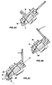
- the housing 3 can assume a first "set” configuration of loading the cartridge C and extracting the infusion ( Figures 2A, 2B ) and a second "unset” configuration of ejecting the cartridge C ( Figure 2C ).
- the means 5 for blocking and/or supporting the housing 3 support at least one free transverse end of the housing 3.
- the housing 3 is rotatably connected, at a bottom portion thereof, to the frame 7 through rotatable connection means, e.g. a pin 32.
- Said rotatable connection means 32 can provide a contrast element 33, associated e.g. to the pin 32 or the seat thereof, its function being that of fostering the rotation of the housing 3 in the change from said first "set" configuration of loading the cartridge C and extracting the infusion to said second "unset" configuration of ejecting the cartridge C.
- the contrast element 33 may be, for instance, a torsion spring.
- rotation of the housing 3 occurs about an axis defined by the above-mentioned pin and lying on a substantially horizontal plane.
- the housing 3 provides a seat 34, shaped so as to receive the cartridge C and limited bottomwise by a filter apt to allow transit of the infusion to an outlet port 35 of the infusion itself.
- the infusion head unit 2 comprises a cartridge-pressure element 21 that, as it will be detailed hereinafter, has the function of exerting a predetermined pressure on the cartridge during the infusion dispensing step.
- infusion machine 1 could provide infusion head units 2 different from the one described hereto.
- the infusion head unit 2 and said housing 3 are arranged longitudinally aligned along an axis V.
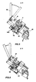
- the infusion head unit 2 is slidably mounted on the frame 7 so as to assume a first position adjoining the housing 3 in which it is lowered ( Figure 4 ) and a second spaced-apart position from the housing 3 in which it is lifted ( Figure 3 ). As shown, e.g., from the sequence of Figures 3 and 4 , the infusion head unit 2 slides internally to the frame 7 along said longitudinal axis V.
- the infusion head unit 2 may be stationary, therefore integral to the frame 7, whereas the housing 3 may be slidably mounted in said frame 7 so as to assume a first position adjoining the infusion head unit 2, in which the housing 3 is lifted, and a second spaced-apart position from the infusion head unit 2, in which the housing 3 is lowered.
- the means 5 for blocking and/or supporting the housing 3 is connected to the frame 7 and, as mentioned hereto, apt to support at least one free transverse end of the housing 3 when the latter lies in said first "set" configuration of loading the cartridge C and extracting the infusion.
- the means 5 for blocking and/or supporting the housing 3 is snap-locking means apt to disengage from said free end when, as it will be evident hereinafter, said infusion head unit 2 changes from said first position adjoining the housing 3, in which it is lowered, to said second spaced-apart position from the housing 3, in which it is lifted.
- the means 5 for blocking and/or supporting the housing 3 comprises:
- the rotatable connection between the main bolt 51 and the secondary bolt 52 is made through suitable rotatable connection means 54, comprising a contrast element 55, which "push" the free portion of the secondary bolt toward an opening 71 of the frame 7 facing the housing 3.
- the means 4 for actuating said infusion head unit 2 and/or said housing 3 comprises:
- the first moving means 41 is moving and contrast means 41 fixed to said infusion head unit 2 and such as to block the latter in its first adjoined position ( Figure 4 ).
- the first moving means 41 comprises a so-called “toggle-type” moving system based on a pair of hinged levers, as shown in Figure 3 .
- the toggle-type moving system is retracted (i.e., said levers form a generally acute angle, as shown in Figure 3 )
- the toggle-type moving system 41 is extended (i.e., said levers are substantially aligned, as shown in Figure 4 ).
- the toggle-type moving system 41 makes a safety blocking of the infusion head unit 2, by overstepping its own end of stroke in a reverse-angle configuration.
- the second moving means 42 is connected to the housing 3 and fixed to the infusion head unit 2, as shown in Figure 1 .
- such second moving means 42 comprises at least one connecting rod 421 connected, at a first end thereof, to said infusion head unit 2 and, at a second end thereof, to said housing 3.
- the connecting rod 421 follows the infusion head unit 2 in its change from the position adjoining the housing 3 to the spaced-apart position from the housing 3, thereby allowing the changing of the housing 3 from said "unset" configuration to said "set” configuration.
- the connecting rod 421 is connected to the infusion head unit 2 by respective rotatable connection means 22.
- the connection between the connecting rod 421 and the housing 3 is made through a slot obtained in the connecting rod 421 for engagement with a respective pin, or shoe, 31 fixed to the housing 3.
- the actuating means 4 comprises a control lever 43 for controlling said first moving means 41 of said infusion head unit 2 and said second moving means 42 of said housing 3.
- the frame 7 provides a "mouth" 72 for inserting the cartridge C at or directly into the cartridge holder 3.
- the cartridge C once inserted into the "mouth” 72, is slidably coupled to insertion guides 73, apt to direct the cartridge to the cartridge holder 3.
- Step 1 Inserting the cartridge into the cartridge holder
- the infusion machine 1 lies in a first configuration ready for use by a user, in which:
- a cartridge C is inserted into the housing 3 through the "mouth" 72 of the frame 7 and the insertion guides 73.
- the cartridge C positions itself in the housing 3 by effect of gravity.
- the cartridge C inserted through the "mouth" 72, remains inside the frame 7, resting on the secondary bolt 52 and being held in position (at the seat 34 of the housing 3) by the insertion guides 73.
- the cartridge C is inserted into the related seat 34 only when the infusion head unit 2 is brought in the first position adjoining the housing 3.
- Step 2 Dispensing the infusion
- the moving means 41 of said infusion head unit 2 in this case the toggle-type moving system, actuates by lowering the lever 43
- the infusion machine 1 lies in a configuration apt to dispense the infusion, wherein:
- the second moving means 42 of the housing 3, being fixed to the infusion head unit 2 are lowered with respect to the preceding configuration.
- the second moving means 42 does not interfere with the housing 3 as the pin 31 connected to the housing 3 moves along the slot ( Figure 2A ) obtained in the connecting rod 421, coming from a position abutting the bottom of the slot to a position substantially opposite to the latter ( Figure 2B ).
- infusion dispensing occurs through the cartridge-pressure element 21 that presses, via a gasket thereof, on the cartridge holder 3 and the cartridge C.
- Step 3 Ejecting and "resetting"
- the toggle-type moving system 41 actuated by the lever 43, lifts the infusion head unit 2 which in turn interferes with the secondary bolt 52, lifting it.
- the bolt 52 is connected to the top portion 510 of the main bolt that, through its bottom portion 511, blocks and supports the housing 3 in said "set” configuration of loading the cartridge C and extracting the infusion.
- the secondary bolt 52 lifts the main bolt 51 which, therefore, "frees” the housing 3, allowing it to rotate about the axis of rotation defined by the rotatable connection means 32.
- the rotation bringing the housing 3 in said second "unset" configuration of ejecting the cartridge C is effected by the combined action of the force of gravity and the contrast element 33.
- ejecting of cartridge C is attained substantially by effect of the action of the gravitational force, with possible contribution of the centrifugal force.
- the secondary bolt 52 during its upstroke meets a striker plane (defined by opening 71) that rotates it so as to break the interference with the infusion head unit 2. This occurs not before the "freeing" of the housing by the main bolt 51.
- the striker plane is defined by the top portion of the frame portion defining the opening 71.
- the blocking and/or supporting means 5 are brought back, by the elastic contrast means 53, into the initial configuration in which it is apt to block and support the housing 3 ( Figure 6 ).
- cartridges of different type like, e.g.: non self-sealing PP cartridges, thermoformed material cartridges, self-sealing cartridges, etc.
Landscapes
- Engineering & Computer Science (AREA)
- Mechanical Engineering (AREA)
- Food Science & Technology (AREA)
- Apparatus For Making Beverages (AREA)
- Infusion, Injection, And Reservoir Apparatuses (AREA)
- External Artificial Organs (AREA)
- Feeding, Discharge, Calcimining, Fusing, And Gas-Generation Devices (AREA)
- Nozzles (AREA)
- Medical Preparation Storing Or Oral Administration Devices (AREA)
Claims (27)
- Maschine (1) zum Spenden von Aufgussgetränken wie Kaffee, Tee und dgl. aus einer Filterkapsel/Kartusche (C) und dgl., mit:- einer Aufgusskopfeinheit (2), die geeignet ist, ein Fluid zu erhitzen und abzugeben, welches sich durch die Kartusche (C) bewegt, um das Aufgussgetränk zu spenden;- einem Gehäuse (3), das in der Lage ist, die Kartusche (C) so zu empfangen, dass sie eine erste, "eingestellte" Konfiguration zum Laden der Kartusche (C) und zum Abgeben des Aufgussgetränks und eine zweite, "nicht eingestellte" Konfiguration zum Ausstoßen der Kartsuche (C) einnimmt; und- einer Einrichtung (4) für das kombinierte Bewegen der Aufgusskopfeinheit (2) und des Gehäuses (3), die in der Lage ist, den Wechsel des Letzteren aus der "eingestellten" Konfiguration in die "nicht eingestellte" Konfiguration zu bewirken, und umgekehrt, in Abhängigkeit von der Bewegung der Aufgusskopfeinheit (2), wobeidie Bewegungseinrichtung (4) ihrerseits aufweist:- eine erste Bewegungseinrichtung (41) der Aufgusskopfeinheit (2); und- eine zweite Bewegungseinrichtung (42) des Gehäuses (3),dadurch gekennzeichnet, dass die zweite Bewegungseinrichtung (42) wenigstens eine Verbindungsstange (421) umfasst, die an ihrem einen Ende mit der Aufgusskopfeinheit (2) und an ihrem anderen Ende mit dem Gehäuse (3) verbunden ist.
- Maschine (1) zum Spenden von Aufgussgetränken nach Anspruch 1, wobei die Aufgusskopfeinheit (2) und das Gehäuse (3) gegenseitig so beweglich sind, dass sie eine erste angrenzende Position einnehmen können, in welcher sie in Kontakt sind, und eine zweite, gegenseitig beabstandete Position, in welcher sie in einer Distanz sind.
- Maschine (1) zum Spenden von Aufgussgetränken nach Anspruch 1 oder 2, wobei die Aufgusskopfeinheit (2) entlang einer Längsachse (V) so beweglich ist, dass sie eine erste Position einnehmen kann, in welcher sie an das Gehäuse (3) angrenzt, und eine zweite Position, in welcher sie von dem Gehäuse (3) beabstandet ist.
- Maschine (1) zum Spenden von Aufgussgetränken nach einem der vorhergehenden Ansprüche, wobei die Aufgusskopfeinheit (2) und das Gehäuse (3) längs ausgerichtet angeordnet sind.
- Maschine (1) zum Spenden von Aufgussgetränken nach einem der vorhergehenden Ansprüche, wobei das Gehäuse (3) mit einem Rahmen (7) der Maschine drehbar verbunden ist, um die "eingestellte" und die "nicht eingestellte" Konfiguration einnehmen zu können.
- Maschine (1) zum Spenden von Aufgussgetränken nach dem vorhergehenden Anspruch, mit einem Kontrastelement (33), welches der drehbaren Verbindung (32) des Gehäuses (3) mit dem Rahmen (7) zugeordnet und dafür ausgebildet ist, die Bewegung des Gehäuses (3) bei dem Wechsel von der ersten, "eingestellten" Konfiguration zu der zweiten, "nicht eingestellten" Konfiguration zu fördern.
- Maschine (1) zum Spenden von Aufgussgetränken nach einem der vorhergehenden Ansprüche, wobei das Gehäuse (3) in der zweiten, "nicht eingestellten" Konfiguration um einen vorbestimmten Winkel (α) in Bezug auf die erste, "eingestellte" Konfiguration zum Laden der Kartusche (C) und des Spendens des Aufgussgetränks gedreht ist.
- Maschine (1) zum Spenden von Aufgussgetränken nach dem vorhergehenden Anspruch, wobei der vorbestimmte Winkel (α) von der Neigung der Maschine (1) gegen den Boden (S) und/oder von einem zugeordneten Hubendeanschlag abhängig ist.
- Maschine (1) zum Spenden von Aufgussgetränken nach Anspruch 7 oder 8, wobei der vorbestimmte Winkel (α) in einem Bereich zwischen etwa 40° und 180° liegt.
- Maschine (1) zum Spenden von Aufgussgetränken nach dem vorhergehenden Anspruch, wobei der vorbestimmte Winkel (α) in einem Bereich zwischen etwa 45° und 90° liegt.
- Maschine (1) zum Spenden von Aufgussgetränken nach dem vorhergehenden Anspruch, wobei der vorbestimmte Winkel (α) etwa 45° beträgt.
- Maschine (1) zum Spenden von Aufgussgetränken nach einem der vorhergehenden Ansprüche, wobei die Gesamtanordnung so getroffen ist, dass dem Gehäuse (3) erlaubt ist, passiv, durch Wirkung der Schwerkraft, aus der ersten, "eingestellten" Konfiguration in die zweite, "nicht eingestellte" Konfiguration zu wechseln.
- Maschine (1) zum Spenden von Aufgussgetränken nach einem der vorhergehenden Ansprüche, wobei sich die erste Bewegungseinrichtung bewegt und eine Kontrasteinrichtung (41) mit der Aufgusskopfeinheit (2) verbunden ist, und zwar so, dass durch Entgegenwirkung die Aufgusskopfeinheit (2) in einer ersten Position, in der sie an das Gehäuse (3) angrenzt, blockiert wird.
- Maschine (1) zum Spenden von Aufgussgetränken nach einem der vorhergehenden Ansprüche, wobei die erste Bewegungseinrichtung (41) ein Bewegungssystem der Kniehebelbauart ist, die auf einem Paar angelenkter Hebel basiert.
- Maschine (1) zum Spenden von Aufgussgetränken nach dem vorhergehenden Anspruch, wobei das Bewegungssystem (41) der Kniehebelbauart eine Sicherheitsblockierung, durch Überschreiten ihres eigenen Hubendes in einer Umkehrwinkelkonfiguration vornimmt, wenn die Aufgusskopfeinheit (2) in der ersten Position ist, in der sie an das Gehäuse (3) angrenzt.
- Maschine (1) zum Spenden von Aufgussgetränken nach einem der vorhergehenden Ansprüche, wobei die zweite Bewegungseinrichtung (42) mit dem Gehäuse (3) verbunden und an der Aufgusskopfeinheit (2) fixiert ist.
- Maschine (1) zum Spenden von Aufgussgetränken nach einem der vorhergehenden Ansprüche, wobei die Verbindungsstange (421) einen Schlitz für einen Leiteingriff mit einem Element (31) zum Verbinden mit dem Gehäuse (3) hat.
- Maschine (1) zum Spenden von Aufgussgetränken nach einem der vorhergehenden Ansprüche, die weiter eine Verriegelungs- und/oder Trageinrichtung (5) zum wahlweisen Tragen und Blockieren des Gehäuses (3) in der ersten, "eingestellten"-Konfiguration zum Laden der Kartusche (C) und zum Abgeben des Aufgussgetränks aufweist.
- Maschine (1) zum Spenden von Aufgussgetränken nach dem vorhergehenden Anspruch, wobei die Einrichtung (5) zum Blockieren und/oder Tragen des Gehäuses (3) durch die Aufgusskopfeinheit (2) wahlweise betätigbar und/oder bewegbar ist.
- Maschine (1) zum Spenden von Aufgussgetränken nach Anspruch 18 oder 19, wobei die Einrichtung (5) zum Blockieren und/oder Tragen des Gehäuses (3) aufweist:- einen Hauptbolzen (51), der einen ersten Teil (510) und einen zweiten Teil (511) hat, die vorzugsweise integral miteinander ausgebildet sind; und- einen zweiten Bolzen (52), der mit dem ersten Teil (510) des Hauptbolzens (51) drehbar verbunden und in der Lage ist, das Gehäuse (3) zu verriegeln.
- Maschine (1) zum Spenden von Aufgussgetränken nach dem vorhergehenden Anspruch, wobei die Einrichtung (5) zum Blockieren und/oder Tragen des Gehäuses (3) eine elastische Kontrasteinrichtung (53) aufweist.
- Maschine (1) zum Spenden von Aufgussgetränken nach einem der vorhergehenden Ansprüche, die eine Führungseinrichtung (73) aufweist zum Einführen der Kartusche an oder in den Kartuschenhalter (3).
- Maschine (1) zum Spenden von Aufgussgetränken nach dem vorhergehenden Anspruch, wobei die Gesamtanordnung der Führungseinrichtung (73) von der Neigung der Maschine (1) gegen den Boden (S) abhängig und so ist, dass sie das Einführen der Kartusche (C) auf oder in den Kartuschenhalter (3) allein durch die Wirkung der Schwerkraft erlaubt.
- Maschine (1) zum Spenden von Aufgussgetränken nach einem der vorhergehenden Ansprüche, die gegen den Boden (S) montierbar geneigt ist.
- Maschine (1) zum Spenden von Aufgussgetränken nach einem der vorhergehenden Ansprüche, die um 45° gegen den Boden (S) montierbar geneigt ist.
- Maschine (1) zum Spenden von Aufgussgetränken nach einem der vorhergehenden Ansprüche, die in Bezug auf den Boden (S) horizontal montierbar ist.
- Maschine (1) zum Spenden von Aufgussgetränken nach einem der vorhergehenden Ansprüche, wobei die Aufgusskopfeinheit (2) in Bezug auf einen Rahmen (7) der Maschine selbst verschiebbar montiert ist.
Priority Applications (3)
| Application Number | Priority Date | Filing Date | Title |
|---|---|---|---|
| PL09713154T PL2242406T3 (pl) | 2008-02-18 | 2009-02-18 | Maszyna do przygotowywania naparu na bazie preparatu znajdującego się we wsadzie wyposażona w urządzenie nastawcze |
| SI200930117T SI2242406T1 (sl) | 2008-02-18 | 2009-02-18 | Stroj za izdajanje poparkov iz pripravka v vsebniku s pripravo za ponovno nastavitev |
| CY20111101219T CY1112163T1 (el) | 2008-02-18 | 2011-12-07 | Μηχανη που χορηγει εγχυματα απο παρασκευασμα ατομικης μεριδας σε φιλτρο και διαθετει διαταξη επαναφορας |
Applications Claiming Priority (2)
| Application Number | Priority Date | Filing Date | Title |
|---|---|---|---|
| IT000092A ITRM20080092A1 (it) | 2008-02-18 | 2008-02-18 | Macchina per erogazione di infusi da un preparato in cialde con dispositivo di riarmo. |
| PCT/IB2009/000284 WO2009104071A1 (en) | 2008-02-18 | 2009-02-18 | Machine for dispensing infusions from a pod preparation having a resetting device |
Publications (2)
| Publication Number | Publication Date |
|---|---|
| EP2242406A1 EP2242406A1 (de) | 2010-10-27 |
| EP2242406B1 true EP2242406B1 (de) | 2011-09-07 |
Family
ID=40291917
Family Applications (1)
| Application Number | Title | Priority Date | Filing Date |
|---|---|---|---|
| EP09713154A Active EP2242406B1 (de) | 2008-02-18 | 2009-02-18 | Maschine zur ausgabe von infusionen aus einem behälterpräparat mit rücksetzvorrichtung |
Country Status (16)
| Country | Link |
|---|---|
| US (1) | US20110017071A1 (de) |
| EP (1) | EP2242406B1 (de) |
| CN (1) | CN101925320B (de) |
| AT (1) | ATE523119T1 (de) |
| AU (1) | AU2009215338A1 (de) |
| BR (1) | BRPI0907516A2 (de) |
| CA (1) | CA2714503A1 (de) |
| CY (1) | CY1112163T1 (de) |
| DK (1) | DK2242406T3 (de) |
| ES (1) | ES2373272T3 (de) |
| IT (1) | ITRM20080092A1 (de) |
| MX (1) | MX2010008967A (de) |
| PL (1) | PL2242406T3 (de) |
| PT (1) | PT2242406E (de) |
| SI (1) | SI2242406T1 (de) |
| WO (1) | WO2009104071A1 (de) |
Families Citing this family (12)
| Publication number | Priority date | Publication date | Assignee | Title |
|---|---|---|---|---|
| PT104810B (pt) | 2009-11-06 | 2012-02-17 | Tecnidelta Equipamentos Hoteleiros Lda | Máquina e processo de extracção de bebidas por infusão |
| US10080459B2 (en) | 2011-11-09 | 2018-09-25 | La Vit Technology Llc | Capsule-based system for preparing and dispensing a beverage |
| US10034570B2 (en) | 2011-11-09 | 2018-07-31 | LaVit Technology LLC | Capsule based system for preparing and dispensing a beverage |
| AU2013217541B2 (en) * | 2012-02-09 | 2017-05-25 | Keurig Green Mountain, Inc. | Beverage forming device and method with cartridge retainer |
| EP2811872B1 (de) * | 2012-02-09 | 2016-11-30 | Keurig Green Mountain, Inc. | Getränkeherstellungsvorrichtung und verfahren mit beweglichem getränkepatronenhalter |
| US9144342B2 (en) * | 2012-02-24 | 2015-09-29 | Main Power Electrical Factory, Ltd. | Pod disposal system |
| ITMI20130617A1 (it) * | 2013-04-15 | 2014-10-16 | Bottarelli Pierangelo | Apparecchio per l'erogazione di caffe' e simili |
| EP2792282B1 (de) * | 2013-04-15 | 2016-03-16 | Bottarelli, Pierangelo | Vorrichtung zur Abgabe von Kaffee und dergleichen |
| US9320382B2 (en) | 2013-07-15 | 2016-04-26 | La Vit Technology Llc | Capsule based system for preparing and dispensing a beverage |
| US10136754B2 (en) | 2014-01-17 | 2018-11-27 | Keurig Green Mountain, Inc. | Beverage machine cartridge holder |
| US9474406B2 (en) | 2014-01-17 | 2016-10-25 | Keurig Green Mountain, Inc. | Apparatus with beverage cartridge holder having movable outlet |
| WO2016059563A1 (en) * | 2014-10-14 | 2016-04-21 | Ides Development Company Limited | Infusion group for machines for the dispensing of beverages in the form of infusion |
Family Cites Families (10)
| Publication number | Priority date | Publication date | Assignee | Title |
|---|---|---|---|---|
| EP1000574A1 (de) * | 1998-11-16 | 2000-05-17 | Societe Des Produits Nestle S.A. | Verfahren und Gerät zum Extrahieren einer geschlossenen Kartusche |
| EP1139832B1 (de) * | 1998-12-24 | 2002-08-21 | Compagnie Méditerraneenne des Cafes | Brühkammer für einen automat zum zubereiten von heissen getränken |
| DE60100785T2 (de) * | 2000-12-29 | 2004-07-15 | Sgl Italia S.R.L. | Kaffeemaschine |
| US6655260B2 (en) * | 2001-04-11 | 2003-12-02 | Keurig, Incorporated | Beverage filter cartridge holder |
| FR2836625B1 (fr) * | 2002-03-01 | 2005-06-24 | Cie Mediterraneenne Des Cafes | Dispositif de production de boisson par infusion |
| ITPN20020093A1 (it) * | 2002-12-02 | 2004-06-03 | Necta Vending Solutions Spa | Gruppo infusore a comando meccanico e fluidodinamico. |
| EP1495702A1 (de) * | 2003-07-10 | 2005-01-12 | Nestec S.A. | Vorrichtung zur Extraktion einer Kartusche |
| ITMI20050854A1 (it) * | 2005-05-12 | 2006-11-13 | Perfect Steam Appliances Ltd | Gruppo di infusione per macchine per la preparazione di bevande |
| CN2820020Y (zh) * | 2005-07-20 | 2006-09-27 | 刘维国 | 组合式饮水咖啡机 |
| CN1879529A (zh) * | 2006-04-03 | 2006-12-20 | 李行 | 咖啡机 |
-
2008
- 2008-02-18 IT IT000092A patent/ITRM20080092A1/it unknown
-
2009
- 2009-02-18 SI SI200930117T patent/SI2242406T1/sl unknown
- 2009-02-18 DK DK09713154.4T patent/DK2242406T3/da active
- 2009-02-18 MX MX2010008967A patent/MX2010008967A/es active IP Right Grant
- 2009-02-18 CA CA2714503A patent/CA2714503A1/en not_active Abandoned
- 2009-02-18 WO PCT/IB2009/000284 patent/WO2009104071A1/en active Application Filing
- 2009-02-18 EP EP09713154A patent/EP2242406B1/de active Active
- 2009-02-18 AT AT09713154T patent/ATE523119T1/de active
- 2009-02-18 PL PL09713154T patent/PL2242406T3/pl unknown
- 2009-02-18 AU AU2009215338A patent/AU2009215338A1/en not_active Abandoned
- 2009-02-18 PT PT09713154T patent/PT2242406E/pt unknown
- 2009-02-18 BR BRPI0907516-0A patent/BRPI0907516A2/pt not_active IP Right Cessation
- 2009-02-18 US US12/865,677 patent/US20110017071A1/en not_active Abandoned
- 2009-02-18 CN CN200980103195XA patent/CN101925320B/zh not_active Expired - Fee Related
- 2009-02-18 ES ES09713154T patent/ES2373272T3/es active Active
-
2011
- 2011-12-07 CY CY20111101219T patent/CY1112163T1/el unknown
Also Published As
| Publication number | Publication date |
|---|---|
| CN101925320B (zh) | 2013-08-28 |
| ATE523119T1 (de) | 2011-09-15 |
| MX2010008967A (es) | 2010-09-07 |
| ES2373272T3 (es) | 2012-02-01 |
| US20110017071A1 (en) | 2011-01-27 |
| WO2009104071A1 (en) | 2009-08-27 |
| CN101925320A (zh) | 2010-12-22 |
| ITRM20080092A1 (it) | 2009-08-19 |
| CY1112163T1 (el) | 2015-12-09 |
| DK2242406T3 (da) | 2012-01-09 |
| PT2242406E (pt) | 2011-12-22 |
| EP2242406A1 (de) | 2010-10-27 |
| AU2009215338A1 (en) | 2009-08-27 |
| CA2714503A1 (en) | 2009-08-27 |
| PL2242406T3 (pl) | 2012-02-29 |
| SI2242406T1 (sl) | 2012-01-31 |
| BRPI0907516A2 (pt) | 2015-07-28 |
Similar Documents
| Publication | Publication Date | Title |
|---|---|---|
| EP2242406B1 (de) | Maschine zur ausgabe von infusionen aus einem behälterpräparat mit rücksetzvorrichtung | |
| AU2002231636B2 (en) | Percolating device | |
| JP5425951B2 (ja) | カプセル抽出装置 | |
| CA2905217C (en) | Capsule machine and components | |
| CA2842533C (en) | Cartridge chamber of extraction system | |
| AU2012298465B2 (en) | Cartridge positioning system | |
| EP1641371B1 (de) | Getränkezubereitungsvorrichtung mit verstellbarer brühkammer | |
| EP2747610B1 (de) | Kartuschenentfernungssystem | |
| EP2244616B1 (de) | Getränkemaschine mit vorrichtung zum laden und entladen von kartuschen | |
| EP2747608B2 (de) | Langlebiger kartuschenlochdorn | |
| WO2007045553A1 (en) | Device for expelling used prepackaged capsules for espresso coffee machines | |
| EP2509475B1 (de) | Maschine zur ausgabe von infusionen | |
| KR102057135B1 (ko) | 자동 커피 제조 기계 | |
| KR102142405B1 (ko) | 캡슐 커피 머신의 캡슐 리셉터클 회동 장치 |
Legal Events
| Date | Code | Title | Description |
|---|---|---|---|
| PUAI | Public reference made under article 153(3) epc to a published international application that has entered the european phase |
Free format text: ORIGINAL CODE: 0009012 |
|
| 17P | Request for examination filed |
Effective date: 20100729 |
|
| AK | Designated contracting states |
Kind code of ref document: A1 Designated state(s): AT BE BG CH CY CZ DE DK EE ES FI FR GB GR HR HU IE IS IT LI LT LU LV MC MK MT NL NO PL PT RO SE SI SK TR |
|
| AX | Request for extension of the european patent |
Extension state: AL BA RS |
|
| 17Q | First examination report despatched |
Effective date: 20110113 |
|
| GRAP | Despatch of communication of intention to grant a patent |
Free format text: ORIGINAL CODE: EPIDOSNIGR1 |
|
| RIN1 | Information on inventor provided before grant (corrected) |
Inventor name: STEFANONI, ROBERTO |
|
| GRAS | Grant fee paid |
Free format text: ORIGINAL CODE: EPIDOSNIGR3 |
|
| GRAA | (expected) grant |
Free format text: ORIGINAL CODE: 0009210 |
|
| RAP1 | Party data changed (applicant data changed or rights of an application transferred) |
Owner name: IDES DEVELOPMENT COMPANY LIMITED |
|
| REG | Reference to a national code |
Ref country code: GB Ref legal event code: FG4D |
|
| REG | Reference to a national code |
Ref country code: CH Ref legal event code: EP |
|
| REG | Reference to a national code |
Ref country code: IE Ref legal event code: FG4D |
|
| REG | Reference to a national code |
Ref country code: DE Ref legal event code: R096 Ref document number: 602009002580 Country of ref document: DE Effective date: 20111110 |
|
| REG | Reference to a national code |
Ref country code: RO Ref legal event code: EPE |
|
| REG | Reference to a national code |
Ref country code: NL Ref legal event code: T3 |
|
| REG | Reference to a national code |
Ref country code: SE Ref legal event code: TRGR |
|
| REG | Reference to a national code |
Ref country code: PT Ref legal event code: SC4A Free format text: AVAILABILITY OF NATIONAL TRANSLATION Effective date: 20111206 |
|
| REG | Reference to a national code |
Ref country code: CH Ref legal event code: NV Representative=s name: PATENTANWAELTE SCHAAD, BALASS, MENZL & PARTNER AG |
|
| REG | Reference to a national code |
Ref country code: DK Ref legal event code: T3 |
|
| PG25 | Lapsed in a contracting state [announced via postgrant information from national office to epo] |
Ref country code: HR Free format text: LAPSE BECAUSE OF FAILURE TO SUBMIT A TRANSLATION OF THE DESCRIPTION OR TO PAY THE FEE WITHIN THE PRESCRIBED TIME-LIMIT Effective date: 20110907 Ref country code: NO Free format text: LAPSE BECAUSE OF FAILURE TO SUBMIT A TRANSLATION OF THE DESCRIPTION OR TO PAY THE FEE WITHIN THE PRESCRIBED TIME-LIMIT Effective date: 20111207 |
|
| REG | Reference to a national code |
Ref country code: ES Ref legal event code: FG2A Ref document number: 2373272 Country of ref document: ES Kind code of ref document: T3 Effective date: 20120201 |
|
| REG | Reference to a national code |
Ref country code: EE Ref legal event code: FG4A Ref document number: E005995 Country of ref document: EE Effective date: 20111205 |
|
| REG | Reference to a national code |
Ref country code: PL Ref legal event code: T3 |
|
| REG | Reference to a national code |
Ref country code: SK Ref legal event code: T3 Ref document number: E 10671 Country of ref document: SK |
|
| REG | Reference to a national code |
Ref country code: GR Ref legal event code: EP Ref document number: 20110402886 Country of ref document: GR Effective date: 20120206 |
|
| PGFP | Annual fee paid to national office [announced via postgrant information from national office to epo] |
Ref country code: LU Payment date: 20120222 Year of fee payment: 4 |
|
| PGFP | Annual fee paid to national office [announced via postgrant information from national office to epo] |
Ref country code: FR Payment date: 20120227 Year of fee payment: 4 Ref country code: IE Payment date: 20120217 Year of fee payment: 4 Ref country code: LT Payment date: 20120120 Year of fee payment: 4 Ref country code: MC Payment date: 20120213 Year of fee payment: 4 |
|
| PGFP | Annual fee paid to national office [announced via postgrant information from national office to epo] |
Ref country code: TR Payment date: 20120213 Year of fee payment: 4 Ref country code: DE Payment date: 20120221 Year of fee payment: 4 Ref country code: SI Payment date: 20120126 Year of fee payment: 4 Ref country code: PT Payment date: 20120216 Year of fee payment: 4 Ref country code: EE Payment date: 20120213 Year of fee payment: 4 Ref country code: BG Payment date: 20120214 Year of fee payment: 4 |
|
| PGFP | Annual fee paid to national office [announced via postgrant information from national office to epo] |
Ref country code: GR Payment date: 20120228 Year of fee payment: 4 Ref country code: SE Payment date: 20120217 Year of fee payment: 4 Ref country code: FI Payment date: 20120213 Year of fee payment: 4 Ref country code: IT Payment date: 20120228 Year of fee payment: 4 Ref country code: BE Payment date: 20120329 Year of fee payment: 4 Ref country code: RO Payment date: 20120127 Year of fee payment: 4 Ref country code: DK Payment date: 20120217 Year of fee payment: 4 Ref country code: LV Payment date: 20120215 Year of fee payment: 4 |
|
| PLBE | No opposition filed within time limit |
Free format text: ORIGINAL CODE: 0009261 |
|
| STAA | Information on the status of an ep patent application or granted ep patent |
Free format text: STATUS: NO OPPOSITION FILED WITHIN TIME LIMIT |
|
| REG | Reference to a national code |
Ref country code: HU Ref legal event code: AG4A Ref document number: E013306 Country of ref document: HU |
|
| PGFP | Annual fee paid to national office [announced via postgrant information from national office to epo] |
Ref country code: HU Payment date: 20120223 Year of fee payment: 4 Ref country code: NL Payment date: 20120228 Year of fee payment: 4 |
|
| 26N | No opposition filed |
Effective date: 20120611 |
|
| PGFP | Annual fee paid to national office [announced via postgrant information from national office to epo] |
Ref country code: CY Payment date: 20120213 Year of fee payment: 4 |
|
| REG | Reference to a national code |
Ref country code: DE Ref legal event code: R097 Ref document number: 602009002580 Country of ref document: DE Effective date: 20120611 |
|
| PG25 | Lapsed in a contracting state [announced via postgrant information from national office to epo] |
Ref country code: MK Free format text: LAPSE BECAUSE OF FAILURE TO SUBMIT A TRANSLATION OF THE DESCRIPTION OR TO PAY THE FEE WITHIN THE PRESCRIBED TIME-LIMIT Effective date: 20110907 |
|
| PGFP | Annual fee paid to national office [announced via postgrant information from national office to epo] |
Ref country code: ES Payment date: 20120224 Year of fee payment: 4 |
|
| PG25 | Lapsed in a contracting state [announced via postgrant information from national office to epo] |
Ref country code: MT Free format text: LAPSE BECAUSE OF FAILURE TO SUBMIT A TRANSLATION OF THE DESCRIPTION OR TO PAY THE FEE WITHIN THE PRESCRIBED TIME-LIMIT Effective date: 20110907 |
|
| REG | Reference to a national code |
Ref country code: PT Ref legal event code: MM4A Free format text: LAPSE DUE TO NON-PAYMENT OF FEES Effective date: 20130819 |
|
| BERE | Be: lapsed |
Owner name: IDES DEVELOPMENT COMPANY LIMITED Effective date: 20130228 |
|
| REG | Reference to a national code |
Ref country code: NL Ref legal event code: V1 Effective date: 20130901 |
|
| REG | Reference to a national code |
Ref country code: DK Ref legal event code: EBP |
|
| REG | Reference to a national code |
Ref country code: LT Ref legal event code: MM4D Effective date: 20130218 |
|
| PG25 | Lapsed in a contracting state [announced via postgrant information from national office to epo] |
Ref country code: MC Free format text: LAPSE BECAUSE OF NON-PAYMENT OF DUE FEES Effective date: 20130228 |
|
| REG | Reference to a national code |
Ref country code: CH Ref legal event code: PL |
|
| REG | Reference to a national code |
Ref country code: SE Ref legal event code: EUG |
|
| REG | Reference to a national code |
Ref country code: EE Ref legal event code: MM4A Ref document number: E005995 Country of ref document: EE Effective date: 20130228 |
|
| REG | Reference to a national code |
Ref country code: GR Ref legal event code: ML Ref document number: 20110402886 Country of ref document: GR Effective date: 20130904 |
|
| GBPC | Gb: european patent ceased through non-payment of renewal fee |
Effective date: 20130218 |
|
| PG25 | Lapsed in a contracting state [announced via postgrant information from national office to epo] |
Ref country code: SE Free format text: LAPSE BECAUSE OF NON-PAYMENT OF DUE FEES Effective date: 20130219 Ref country code: CH Free format text: LAPSE BECAUSE OF NON-PAYMENT OF DUE FEES Effective date: 20130228 Ref country code: LI Free format text: LAPSE BECAUSE OF NON-PAYMENT OF DUE FEES Effective date: 20130228 Ref country code: NL Free format text: LAPSE BECAUSE OF NON-PAYMENT OF DUE FEES Effective date: 20130901 Ref country code: DE Free format text: LAPSE BECAUSE OF NON-PAYMENT OF DUE FEES Effective date: 20130903 Ref country code: CZ Free format text: LAPSE BECAUSE OF NON-PAYMENT OF DUE FEES Effective date: 20130218 Ref country code: EE Free format text: LAPSE BECAUSE OF NON-PAYMENT OF DUE FEES Effective date: 20130228 Ref country code: LT Free format text: LAPSE BECAUSE OF NON-PAYMENT OF DUE FEES Effective date: 20130218 Ref country code: GR Free format text: LAPSE BECAUSE OF NON-PAYMENT OF DUE FEES Effective date: 20130904 Ref country code: IS Free format text: LAPSE BECAUSE OF FAILURE TO SUBMIT A TRANSLATION OF THE DESCRIPTION OR TO PAY THE FEE WITHIN THE PRESCRIBED TIME-LIMIT Effective date: 20130829 Ref country code: HU Free format text: LAPSE BECAUSE OF NON-PAYMENT OF DUE FEES Effective date: 20130219 Ref country code: PT Free format text: LAPSE BECAUSE OF NON-PAYMENT OF DUE FEES Effective date: 20130819 Ref country code: FI Free format text: LAPSE BECAUSE OF NON-PAYMENT OF DUE FEES Effective date: 20130218 Ref country code: SK Free format text: LAPSE BECAUSE OF NON-PAYMENT OF DUE FEES Effective date: 20130218 |
|
| REG | Reference to a national code |
Ref country code: SK Ref legal event code: MM4A Ref document number: E 10671 Country of ref document: SK Effective date: 20130218 |
|
| REG | Reference to a national code |
Ref country code: FR Ref legal event code: ST Effective date: 20131031 |
|
| PG25 | Lapsed in a contracting state [announced via postgrant information from national office to epo] |
Ref country code: CY Free format text: LAPSE BECAUSE OF NON-PAYMENT OF DUE FEES Effective date: 20130218 Ref country code: LV Free format text: LAPSE BECAUSE OF NON-PAYMENT OF DUE FEES Effective date: 20130218 |
|
| REG | Reference to a national code |
Ref country code: SI Ref legal event code: KO00 Effective date: 20131017 |
|
| REG | Reference to a national code |
Ref country code: IE Ref legal event code: MM4A |
|
| REG | Reference to a national code |
Ref country code: DE Ref legal event code: R119 Ref document number: 602009002580 Country of ref document: DE Effective date: 20130903 |
|
| PG25 | Lapsed in a contracting state [announced via postgrant information from national office to epo] |
Ref country code: IT Free format text: LAPSE BECAUSE OF NON-PAYMENT OF DUE FEES Effective date: 20130218 |
|
| PG25 | Lapsed in a contracting state [announced via postgrant information from national office to epo] |
Ref country code: DK Free format text: LAPSE BECAUSE OF NON-PAYMENT OF DUE FEES Effective date: 20130228 Ref country code: FR Free format text: LAPSE BECAUSE OF NON-PAYMENT OF DUE FEES Effective date: 20130228 Ref country code: IE Free format text: LAPSE BECAUSE OF NON-PAYMENT OF DUE FEES Effective date: 20130218 Ref country code: BE Free format text: LAPSE BECAUSE OF NON-PAYMENT OF DUE FEES Effective date: 20130228 Ref country code: GB Free format text: LAPSE BECAUSE OF NON-PAYMENT OF DUE FEES Effective date: 20130218 |
|
| PG25 | Lapsed in a contracting state [announced via postgrant information from national office to epo] |
Ref country code: SI Free format text: LAPSE BECAUSE OF NON-PAYMENT OF DUE FEES Effective date: 20130219 Ref country code: RO Free format text: LAPSE BECAUSE OF NON-PAYMENT OF DUE FEES Effective date: 20130218 |
|
| PG25 | Lapsed in a contracting state [announced via postgrant information from national office to epo] |
Ref country code: PL Free format text: LAPSE BECAUSE OF NON-PAYMENT OF DUE FEES Effective date: 20130218 |
|
| REG | Reference to a national code |
Ref country code: PL Ref legal event code: LAPE |
|
| REG | Reference to a national code |
Ref country code: ES Ref legal event code: FD2A Effective date: 20140609 |
|
| PG25 | Lapsed in a contracting state [announced via postgrant information from national office to epo] |
Ref country code: ES Free format text: LAPSE BECAUSE OF NON-PAYMENT OF DUE FEES Effective date: 20130219 |
|
| PG25 | Lapsed in a contracting state [announced via postgrant information from national office to epo] |
Ref country code: LU Free format text: LAPSE BECAUSE OF NON-PAYMENT OF DUE FEES Effective date: 20130218 Ref country code: BG Free format text: LAPSE BECAUSE OF NON-PAYMENT OF DUE FEES Effective date: 20130228 |
|
| PG25 | Lapsed in a contracting state [announced via postgrant information from national office to epo] |
Ref country code: TR Free format text: LAPSE BECAUSE OF NON-PAYMENT OF DUE FEES Effective date: 20130218 |
|
| PGFP | Annual fee paid to national office [announced via postgrant information from national office to epo] |
Ref country code: AT Payment date: 20180219 Year of fee payment: 10 |
|
| REG | Reference to a national code |
Ref country code: AT Ref legal event code: MM01 Ref document number: 523119 Country of ref document: AT Kind code of ref document: T Effective date: 20190218 |
|
| PG25 | Lapsed in a contracting state [announced via postgrant information from national office to epo] |
Ref country code: AT Free format text: LAPSE BECAUSE OF NON-PAYMENT OF DUE FEES Effective date: 20190218 |