EP2242238A1 - Mobile Endgerätevorrichtung - Google Patents
Mobile Endgerätevorrichtung Download PDFInfo
- Publication number
- EP2242238A1 EP2242238A1 EP10157770A EP10157770A EP2242238A1 EP 2242238 A1 EP2242238 A1 EP 2242238A1 EP 10157770 A EP10157770 A EP 10157770A EP 10157770 A EP10157770 A EP 10157770A EP 2242238 A1 EP2242238 A1 EP 2242238A1
- Authority
- EP
- European Patent Office
- Prior art keywords
- cabinet
- keyboard
- slide pins
- slide
- open state
- Prior art date
- Legal status (The legal status is an assumption and is not a legal conclusion. Google has not performed a legal analysis and makes no representation as to the accuracy of the status listed.)
- Granted
Links
Images





Classifications
-
- H—ELECTRICITY
- H04—ELECTRIC COMMUNICATION TECHNIQUE
- H04M—TELEPHONIC COMMUNICATION
- H04M1/00—Substation equipment, e.g. for use by subscribers
- H04M1/02—Constructional features of telephone sets
- H04M1/0202—Portable telephone sets, e.g. cordless phones, mobile phones or bar type handsets
- H04M1/0206—Portable telephones comprising a plurality of mechanically joined movable body parts, e.g. hinged housings
- H04M1/0247—Portable telephones comprising a plurality of mechanically joined movable body parts, e.g. hinged housings comprising more than two body parts
-
- G—PHYSICS
- G06—COMPUTING OR CALCULATING; COUNTING
- G06F—ELECTRIC DIGITAL DATA PROCESSING
- G06F1/00—Details not covered by groups G06F3/00 - G06F13/00 and G06F21/00
- G06F1/16—Constructional details or arrangements
- G06F1/1613—Constructional details or arrangements for portable computers
- G06F1/1633—Constructional details or arrangements of portable computers not specific to the type of enclosures covered by groups G06F1/1615 - G06F1/1626
- G06F1/1662—Details related to the integrated keyboard
- G06F1/1666—Arrangements for reducing the size of the integrated keyboard for transport, e.g. foldable keyboards, keyboards with collapsible keys
-
- H—ELECTRICITY
- H04—ELECTRIC COMMUNICATION TECHNIQUE
- H04M—TELEPHONIC COMMUNICATION
- H04M1/00—Substation equipment, e.g. for use by subscribers
- H04M1/02—Constructional features of telephone sets
- H04M1/0202—Portable telephone sets, e.g. cordless phones, mobile phones or bar type handsets
- H04M1/0206—Portable telephones comprising a plurality of mechanically joined movable body parts, e.g. hinged housings
- H04M1/0208—Portable telephones comprising a plurality of mechanically joined movable body parts, e.g. hinged housings characterized by the relative motions of the body parts
- H04M1/0235—Slidable or telescopic telephones, i.e. with a relative translation movement of the body parts; Telephones using a combination of translation and other relative motions of the body parts
- H04M1/0237—Sliding mechanism with one degree of freedom
Definitions
- the present invention relates to a mobile terminal apparatus.
- Japanese Patent Application Publication No. 2005-167847 discloses a mobile communication terminal in which sliding operation is simplified.
- a display cabinet having a display unit is disposed slidably on an operation cabinet having a button operation unit, and the display unit slides to shift to the exposure state in which the button operation unit is exposed or the hidden state in which the button operation unit is hidden by the display cabinet.
- An antenna holding unit of the operation cabinet has a first compression coil spring and the display cabinet is urged by the urging force of the first compression coil spring in the direction in which the hidden state shifts to the exposure state, making the slide operation for shifting to the exposure state easier.
- buttons of the button operation unit are disposed in an area approximately half the area of the operation cabinet. This causes the following problems.
- a mobile terminal apparatus including a first cabinet; a second cabinet; a slide holding mechanism for holding a first cabinet and a second cabinet slidable during a shift from an closed state in which the first cabinet and the second cabinet substantially fully overlap one another to an open state in which a certain part of the first cabinet and a certain part of the second cabinet overlap one another; a keyboard held within the second cabinet, the keyboard being disposed movable in slide directions of the first cabinet and the second cabinet; a first urging member urging the keyboard in an ejection direction opposite to a direction in which the first cabinet moves when the first cabinet and the second cabinet are placed in the open state; a hook disposed at a retraction side end opposite to an ejection side end, which is an end in the ejection direction of the keyboard; a keyboard lock member including a projection projecting from a sliding contact surface of the second cabinet, the sliding contact surface being in sliding contact with the first cabinet, and a notch engaged with the hook, the keyboard lock member being
- the hook when the first cabinet and the second cabinet are placed in the closed state, the hook is engaged with the notch of the keyboard lock member, so that the keyboard is held within the second cabinet.
- the hook is removed from the notch of the keyboard lock member, so that the first urging member urges the keyboard in the ejection direction and the keyboard ejects from the second body. This increases the input operation plane of the keyboard.
- the spacing between adjacent keys on the keyboard can be increased and the input operation becomes easier.
- the mobile terminal apparatus has a first cabinet and second cabinet mutually sliding to enter an open state or closed state, that is preferably applied to portable devices such as, for example, a mobile phone, a PHS (Personal Handyphone System) phone, a PDA (Personal Digital Assistant) apparatus, a hand-held game machine, and a digital camera.
- portable devices such as, for example, a mobile phone, a PHS (Personal Handyphone System) phone, a PDA (Personal Digital Assistant) apparatus, a hand-held game machine, and a digital camera.
- the present invention also preferably relates to a mobile terminal apparatus that allows a keyboard held within the second cabinet to eject and provide a larger input plane for easier input operation when the first cabinet and the second cabinet mutually slide to enter the open state or allows a display unit to have improved visibility by slanting the first body or the second body on which the display unit is disposed when the first body and the second body enter the open state.
- Fig. 1 illustrates a mobile phone in the closed state according to an embodiment of the present invention.
- Figs. 2 and 3 illustrate the mobile phone in an open state according to the embodiment.
- Fig. 1 is a diagram, seen from the right side, illustrating the substantial components when the mobile phone is placed in a closed state.
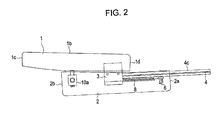
- Fig. 2 is a diagram, seen from the left side, illustrating the substantial components of the mobile phone in the open state.
- Fig. 3 is a diagram, seen from the bottom, illustrating the substantial components of the mobile phone in the open state, seen from the bottom.
- this mobile phone includes a first cabinet 1, which is substantially rectangular-parallelepiped-shaped, a second cabinet 2, which is substantially rectangular-parallelepiped-shaped and has substantially the same size as in the first cabinet 1, and a slide holding mechanism 3, which holds the first cabinet and the second cabinet slidable during a shift from a closed state (see Fig. 1 ) in which the first cabinet and the second cabinet substantially fully overlap one another to an open state (see Figs. 2 and 3 ) in which a part of the first cabinet and a part of the second cabinet overlap one another.
- the first cabinet 1 has a display unit such as an electro luminescence display unit on a display plane 1b opposite to a sliding contact surface 1a that makes sliding contact with the second cabinet 2. Accordingly, in this mobile phone, the display unit is exposed regardless of whether the first cabinet and the second cabinet are placed in the open state or in the closed state.
- a display unit such as an electro luminescence display unit on a display plane 1b opposite to a sliding contact surface 1a that makes sliding contact with the second cabinet 2. Accordingly, in this mobile phone, the display unit is exposed regardless of whether the first cabinet and the second cabinet are placed in the open state or in the closed state.
- a keyboard 4 which is substantially rectangular, is held within the second cabinet 2. More specifically, stepped machining is applied to ends 4a and 4b of the shorter sides of the keyboard 4.
- the second cabinet 2 has a keyboard insertion opening 5 into which the steps formed on the ends of the keyboard 4 fit.
- the keyboard 4 is held within the second body 2 with step-like ends 4a and 4b of the keyboard 4 inserted into the keyboard insertion opening 5, so that an operation plane 4c of the keyboard 4 is exposed.
- stepped machining is applied to the ends 4a and 4b of the shorter sides, when the keyboard 4 is retracted into the second cabinet 2 via the keyboard insertion opening 5, the keyboard 4 is allowed to move only in the directions in which the keyboard 4 is retracted and ejected (referred to below as a retraction direction and ejection direction, respectively), indicated by the arrows in Fig. 4 , and prohibited to move in the thickness direction of the second cabinet 2.
- One end of the keyboard 4 is secured by a screw 6 to the second cabinet 2 as shown Fig. 1 and the other end is urged in the ejection direction by a spring member 8 secured by a screw 7 to substantially the middle of the longer side at a retraction side end 4d of the keyboard 4 as shown in Fig. 3 .
- the keyboard 4 has a pair of hooks 9a and 9b projecting in the retraction direction from the longer side at the retraction side end 4d at positions closer to the shorter sides at the ends 4a and 4b of the keyboard 4 with the screw 7 centered, as shown in Fig. 3 .
- the second cabinet 2 has a pair of keyboard lock members 10a and 10b secured at positions corresponding to the hooks 9a and 9b along the longer side at the anti-ejection side end 2b opposite to the longer side at the ejection side end 2a of the keyboard 4.
- the pair of hooks 9a and 9b are disposed on the keyboard 4 in this example, but only one hook or three or more hooks can be disposed on the keyboard 4.
- the pair of keyboard lock members 10a and 10b are disposed on the second cabinet 2 in this example, but only one keyboard lock member or three or more keyboard lock members can be disposed on the second cabinet 2.
- Fig. 5 is a perspective view illustrating the keyboard lock member 10b.
- the keyboard lock member 10a also has the same structure, so the following description is applicable to the keyboard lock member 10a.
- the keyboard lock member 10b has a cabinet 11, which is substantially rectangular-parallelepiped-shaped, a projection 12, which projects from substantially the center of an upper surface 11a of a main body 11, a notch 13 with which the hook 9b is engaged.
- the second cabinet 2 has slide holding openings 14 shown in Fig. 6A in which the keyboard lock member 10a and 10b are disposed.
- the keyboard lock members 10b is inserted into the slide holding opening 14 from a bottom 11b of the cabinet 11 shown in Fig. 5 so as to move only in the direction orthogonal to the slide direction of the second cabinet 2 as shown in Fig. 6B .
- the keyboard lock member 10b is disposed in the second cabinet 2 movable only in a lock direction in which the notch 13 of the keyboard lock member 10b is engaged with the hook 9b disposed on the keyboard 4 and in a lock release direction in which the notch 13 of the keyboard lock member 10b is removed from the hook 9b disposed on the keyboard 4.
- the keyboard lock member 10b is inserted into the slide holding opening 14 together with a spring member 15 as shown in Fig. 3 . Accordingly, the keyboard lock member 10b is disposed on the second cabinet 2 so as to be urged in the direction in which the keyboard lock member 10b is engaged with the notch 9b.
- the sliding contact surface 1a of the first cabinet 1 that makes sliding contact with the second cabinet 2 has a sliding groove 16 in which the projection 12 of the keyboard lock member 10b slides, the sliding groove 16 being disposed along the slide direction of the first cabinet 1 as shown in Fig. 7 .
- Another sliding groove 16 corresponds to the projection 12 of the keyboard lock member 10a is also disposed on the first cabinet 1. The structure will be described below.
- the sliding groove 16 has a lock releasing groove 18, which moves the keyboard lock member 10b via the projection 12 in the direction (lock direction) in which the hook 9b is engaged with the notch 13 of the keyboard lock member 10b when the first cabinet 1 and the second cabinet 2 are placed in the closed state or in the direction (lock release direction) in which the notch 13 of the keyboard lock member 10b is removed from the hook 9b when the first cabinet 1 and the second cabinet 2 are placed in the open state.
- the keyboard lock members 10a and 10b are moved via the projections 12 along the sliding grooves 16 in the lock direction and the keyboard 4 is retracted into the second cabinet 2.
- the keyboard lock members 10a and 10b are moved via the projections 12 along the sliding grooves 16 in the lock release direction and the keyboard 44 held within the second cabinet 2 ejects from the second cabinet 2.
- the diameter of the projections 12 is less than the width of the sliding grooves 16 so that the keyboard lock members 10a and 10b can move in the lock direction and the lock release direction, which are lateral directions of the sliding grooves 16, when the projections 12 of the keyboard lock members 10a and 10b are inserted into the sliding grooves 16.
- the reason why the keyboard lock members 10a and 10b are movable in the lock direction and the lock release direction is that there is a clearance between the projections 12 and the sliding grooves 16.
- the first cabinet 1 is tapered from the vicinity of substantially the center of the first cabinet 1 to a surface 1c away from the keyboard (referred to below as an off-keyboard side surface) so that the width of the off-keyboard side surface 1c is less than the width of a surface 1d close to the keyboard (referred to below as a keyboard side surface).
- the second cabinet 2 is thickened from the vicinity of substantially the center of the second cabinet 2 to a side 2c (referred to below as an anti-keyboard-ejection side surface) opposite to the keyboard ejection side surface 2d so that the width of the anti-keyboard-ejection side surface 2c is larger than the width of the keyboard ejection side surface 2d.
- a side 2c referred to below as an anti-keyboard-ejection side surface
- the sum of the width of the off-keyboard side surface 1c of the first cabinet 1 and the width of the anti-keyboard-ejection side surface 2c of the second cabinet 2 substantially equals the sum of the width of the keyboard side surface 1d of the first cabinet 1 and the width of the keyboard ejection side surface 2d of the second cabinet 2 due to slant machining applied to the first cabinet and the second cabinet.
- the first cabinet 1 slides in a slanted attitude so that the highest point of the off-keyboard side surface 1c is higher than the highest point of the keyboard side surface 1d as shown in Fig. 2 due to the slant machining applied to the first cabinet 1 and the second cabinet 2 so as to improve the visibility of the display unit of the first cabinet 1.
- Fig. 8 illustrates only the substantial components when the first cabinet 1 and the second cabinet 2 are placed in the closed state.
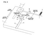
- Fig. 9 illustrates only the substantial components when the first cabinet 1 and the second cabinet 2 are placed in the open state.
- the first cabinet 1 and the second cabinet 2 When the first cabinet 1 and the second cabinet 2 are placed in the closed state, the first cabinet 1 and the second cabinet 2 substantially fully overlap one another and the keyboard 4 is held within the second cabinet 2, as shown in Fig. 1 .
- the spring members 15 in Fig. 8 urges the keyboard lock members 10a and 10b in the lock direction, the projections 12 of the keyboard lock members 10a and 10b are moved in the locking groove 17 of the siding grooves 16 in the lock direction, and the keyboard lock members 10a and 10b are moved in the lock direction via the projections 12.
- the lock releasing grooves 18 have a shape that moves the keyboard lock members 10a and 10b in the lock release direction, so the keyboard lock members 10a and 10b move in the lock release direction along the lock releasing grooves 18 via the projections 12 against the urging force of the spring members 15.
- the keyboard 4 is urged by the spring member 8 in the ejection direction as described above. Accordingly, when the hooks 9a and 9b are removed from the notches 13 of the keyboard lock members 10a and 10b, the keyboard 4 is ejected by an urging force of the spring member 8 outside the second cabinet 2. This causes the mobile phone then to be placed in the open state shown in Fig. 2 .
- the keyboard 4 and the second cabinet 2 have a stopper (not shown) that stops the ejection of the keyboard 4 at a certain position.
- the keyboard 4 held within the second cabinet 2 ejects outside the second cabinet 2 when the first cabinet 1 and the second cabinet 2 are placed in the open state. Accordingly, even though the first cabinet 1 and the second cabinet 2 overlap in the open state, the input operation plane substantially equal to the area of the second cabinet 2 can be obtained.
- the input operation plane of the keyboard 4 Since the input operation plane of the keyboard 4 is enlarged, the spacing between adjacent keys on the keyboard can be increased and the input operation becomes easier. In addition, since the input operation plane of the keyboard 4 is enlarged, keys with a larger physical size can be disposed on the keyboard 4 and the input operation becomes easier. Alternatively, since the input operation plane of the keyboard 4 is enlarged, the number of keys that can be disposed on the keyboard increases.
- the first cabinet 1 is tapered from the vicinity of substantially the center of the first cabinet 1 to the off-keyboard side surface 1c so that the width of the off-keyboard side surface 1c is less than the width of the keyboard side surface 1d, as shown in Fig. 1 .
- the second cabinet 2 is thickened from the vicinity of substantially the center of the second cabinet 2 to the anti-keyboard-ejection side surface 2c opposite to the keyboard ejection side surface 2d so that the width of the anti-keyboard-ejection side surface 2c is larger than the width of the keyboard ejection side surface 2d.
- the slide holding mechanism 3 slides the first cabinet 1 and the second cabinet 2 along the above slopes in the open direction to slant the first cabinet 1 so that the highest point of the off-keyboard side surface 1c of the first cabinet 1 is higher than the highest point of the keyboard side surface 1d of the first cabinet 1 as shown in Fig. 2 .
- a force in a lateral direction and in the ejection direction of the keyboard 4 is applied to the first cabinet 1 and a force in the lateral direction and in a direction opposite to the ejection direction of keyboard 4 is applied to the keyboard 4 ejecting from the second cabinet 2.
- This causes the first cabinet 1 to move in the ejection direction of the keyboard 4 and the keyboard 4 to move the retraction direction in Fig. 9 against the urging force of the spring member 8.
- the first cabinet 1 and the second cabinet 2 When the first cabinet 1 and the second cabinet 2 are placed in the closed state from the open state, the first cabinet 1 moves in the ejection direction of the keyboard 4. So, the projections 12 of the keyboard lock members 10a and 10b move from the lock releasing grooves 18 of the sliding grooves 16 to the locking grooves 17 when the hooks 9a and 9b secured to the keyboard 4 reaches the positions of the keyboard lock members 10a and 10b disposed on the second cabinet 2, and the keyboard lock members 10a and 10b move in the lock direction via the projections 12.
- the slant machining is applied to the first cabinet 1 and the second cabinet 2, but the sum of the width of the off-keyboard side surface 1c of the first cabinet 1 and the width of the anti-keyboard-ejection side surface 2c of the second cabinet 2 substantially equals the sum of the width of the keyboard side surface 1d of the first cabinet 1 and the width of the keyboard ejection side surface 2d of the second cabinet 2. Accordingly, the entire shaped of the mobile phone is substantially rectangle-parallelepiped-shaped in the closed state even though the slant machining is applied to the first cabinet 1 and the second cabinet 2.
- the keyboard 4 held within the second cabinet 2 ejects externally. Accordingly, in the open state, the input operation plane that substantially equals the area of the second cabinet 2 can be obtained even though the first cabinet 1 and the second cabinet 2 mutually overlap.
- the input operation plane of the keyboard 4 Since the input operation plane of the keyboard 4 is enlarged, the distance between adjacent keys on the keyboard can be increased and input operation becomes easier. In addition, since the input operation plane of the keyboard 4 is enlarged, keys with a larger physical size can be disposed on the keyboard 4 and input operation becomes easier. Alternatively, since the input operation plane of the keyboard 4 is enlarged, the number of keys that can be disposed on the keyboard 4 increases.
- the first cabinet 1 is tapered from the vicinity of substantially the center of the first cabinet 1 to the off-keyboard side surface 1c so that the width of the off-keyboard side surface 1c is less than the width of the keyboard side surface 1d.
- the second cabinet 2 is thickened from the vicinity of substantially the center of the second cabinet 2 to the anti-keyboard-ejection side surface 2c opposite to the keyboard ejection side surface 2d so that the width of the anti-keyboard-ejection side surface 2c of the second cabinet 2 is larger than the width of the keyboard ejection side surface 2d.
- the slide holding mechanism 3 slides the first cabinet 1 and the second cabinet 2 along the slopes in the open direction to slant the first cabinet 1 so that the highest point of the off-keyboard side surface 1c of the first cabinet 1 is higher than the highest point of the keyboard side surface 1d of the first cabinet 1 as shown in Fig. 2 .
- the first cabinet 1 and the second cabinet 2 can be opened and closed smoothly in a semi-automatic manner and the first cabinet 1 can be slanted so that the highest point of the off-keyboard side surface 1c of the first cabinet 1 is higher than the highest point of the keyboard side surface 1d of the first cabinet 1 when the first cabinet 1 and the second cabinet 2 are placed in the open state in order to improve the visibility of the display unit.
- the mobile phone according to the other embodiment differs only in this point from the mobile phone according to the embodiment. Accordingly, only the difference between the embodiments will be described later to omit duplicate description.
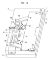
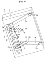
- Figs. 10 and 11 illustrate the substantial components when the mobile phone according to the other embodiment is placed in the closed state.
- Fig. 12 illustrates the substantial components when the mobile phone according to the other embodiment is placed in the open state. More specifically, Fig. 10 is a perspective view of the substantial components in the closed state, seen from the first cabinet side.
- Fig. 11 is a perspective view of the substantial components in the closed state, seen from the second cabinet side.
- Fig. 12 is a perspective view of the substantial components in the open state, seen from the first cabinet side.
- Fig. 10 to 12 components such as the keyboard 4 and keyboard lock members 10a and 10b, which are described in the embodiment, are not shown so that the structure and operation of the mobile phone according to the other embodiment can easily be understood.
- the mobile phone has a slide holding mechanism that includes a pair of slide pins 20, a guide shaft 21, which supports the slide pins 20 movably along the longitudinal direction and rotatably in the circumferential direction, guide plate 23, which has a pair of guide openings 22 with a length allowing the slide pins to move along the guide shaft 21 during switching between the closed state and the open state of the first cabinet 1 and the second cabinet 2, a pair of arm members 24, each of which has one end connected to the slide pin 20 and another end connected to the first cabinet 1, and a pair of spring members 25, each of which has one end connected to the slide pin 20 and another end connected to the first cabinet 2 and an urge direction changes.
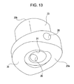
- Each of the slide pins 20 is substantially cylindrical as shown in Fig. 13 and has a guide shaft insertion hole 26 passing through the side in the diameter direction.
- a spring stopper insertion hole 31 is disposed in a bottom 20a of each slide pins 20 in the direction orthogonal to the diameter direction of each slide pins 20.
- the first cabinet 1 is slanted so that the highest point of the off-keyboard side surface 1c of the first cabinet 1 is higher than the highest point of the keyboard side surface 1d when the first cabinet 1 and the second cabinet 2 are placed in the open state.
- the slide pins 20 rotates in the circumferential direction of the guide shaft 21. The rotation brings the bottom 20a of each slide pin 20 into contact with the second cabinet 2, possibly preventing the first cabinet 1 from slanting.
- a slanted surface 35 to which slant machining corresponding to the slant of the first cabinet 1 is applied is disposed on the part on the bottom 20a of the slide pin 20 that makes contact with the second cabinet 2 when the first cabinet 1 and the second cabinet 2 are placed in the open state.
- the slant machining corresponding to the slant of the first cabinet 1 is applied to the part on the bottom 20a of each slide pin 20 that is in contact with the second cabinet 2 when the first cabinet 1 and the second cabinet 2 are placed in the open state, but contact prevention holes (holes for relieving bottoms 20a of each slide pins 20 when the first cabinet 1 and the second cabinet 2 are placed in the open state) may be disposed in the bottom 20a of each slide pin 20 instead of the slant machining.
- the guide shaft 21 is a cylindrical member with a diameter slightly smaller than the diameter of the guide shaft insertion holes 26 disposed in the slide pins 20.
- the guide shaft 21 is inserted into the guide shaft insertion hole 26 of each slide pin 20 as shown in Figs. 10 to 12 so as to support each slide pin 20 movably along the guide shaft 21 and rotatably in the circumferential direction of the guide shaft 21.
- the guide plate 23 which is rectangular in shape, has a pair of the guide openings 22, which are substantially oblong, along the longitudinal direction.
- the guide plate 23 also has a pair of guide shaft supporting holes 27 for supporting the guide shaft 21 along the longitudinal direction of the guide plate 23.
- One end and the other end of the guide shaft 21 that was inserted into the guide shaft insertion holes 26 of the slide pins 20 are inserted into the guide shaft supporting holes 27.
- a screwing hole 28 for screwing the guide plate 23 is disposed in one or both ends on the shorter sides of the guide plate 23.
- the guide plate 23 is secured along the anti-keyboard-ejection side surface 2c of the second cabinet 2 with a screw inserted into the screwing hole 28 as shown in Figs. 10 to 12 .
- the slide pins 20 are inserted into the guide openings 22 of the guide plate 23 as shown in Figs. 10 to 12 ; the guide openings 22 guide the movement of the slide pins 22 along the guide shaft 21 to switch between the closed state and the open state of the first cabinet 1 and the second cabinet 2.
- the slide pins 20 moves within the guide openings 22 of the guide plate 23 in the open direction and the closed direction as shown in Fig. 14 to switch between the closed state and the open state of the first cabinet 1 and the second cabinet 2.
- the slide pins 20 rotates in the circumferential direction of the guide shaft 21 and slants as described above. Since the guide plate 23 is secured to the second cabinet 2, if the slide pins 20 slant, the diameter of the slide pins 20 in the guide openings 22 of the guide plate 23 changes depending on whether the first cabinet 1 and the second cabinet 2 are placed in the closed state or in the open state.
- the diameter of the slide pins 20 in the guide openings 22 when the first cabinet 1 and the second cabinet 2 are placed in the open state in which the slide pins 20 slant is greater than the diameter of the slide pins 20 in the guide openings 22 when the first cabinet 1 and the second cabinet 2 are placed in the closed state in which the slide pins 20 do not slant.
- the inside widths B1 and B2 in the lateral direction, in which the slide pins 20 are located when the first cabinet 1 and the second cabinet 2 are placed in the open state are larger than the outside widths A1 and A2 in the lateral direction, in which the slide pins 20 are located when the first cabinet 1 and the second cabinet 2 are placed in the closed state.
- the guide openings 22 of the guide plate 23 are formed to have mutually different inside and outside widths so that changes in the diameter of the slide pins 20 that are caused when the slide pins 20 are slanted can be accommodated.
- the arm members 24 is strip-shaped as shown in Figs. 10 to 12 .
- the arm member 24 has a slide pin insertion hole 24a in the vicinity of one end, which is a through hole in the thickness direction and a cabinet fixing hole 24a in the vicinity of the other end, which is a through hole in the thickness direction.
- the diameter of the slide pin insertion hole 24a disposed in the vicinity of one end of the arm member 24 is slightly larger than the diameter of an upper portion 20b opposite to a bottom 20a on which the guide shaft 21 of the slide pin 20 is disposed.
- the arm member 24 is connected to the slide pin 20 with the upper portion 20b of the slide pin 20 inserted into the slide pin insertion hole 24a so that the arm member 24 can rotate in the circumferential direction the slide pin 20.
- a fixing pin 29 with smooth a circumferential surface is inserted into the cabinet fixing hole 24b disposed in the vicinity of the other end of the arm member 24.
- the arm members 24 are secured to the vicinities of both corners of the first cabinet 1 in the closed direction via the fixing pins 29.
- the circumferential surface of the fixing pin 29 is smooth, so the arm members 24 can rotate in the circumferential direction of the fixing pins 29.
- the spring member 25 is corrugated as shown in Figs. 10 to 12 , or meandering. As shown in Fig. 11 , one end 25a of the spring member 25 is secured to each slide pin 20 with a spring stopper 30 inserted into the spring stopper insertion hole 31.
- the other end 25b of the spring member 25 is secured to the second cabinet 2 by screw 32 as shown in Figs. 11 and 12 so that the slide pins 20 are urged to increase the distance between the slide pins 20 when the first cabinet 1 and the second cabinet 2 are placed in the closed state.
- the direction in which the slide pins 20 are urged by the spring member 25 changes depending on the open/close state of the first cabinet 1 and the second cabinet 2 as described below so that the first cabinet 1 and the second cabinet 2 can be opened and closed smoothly in a semi-automatic manner.
- the slide pins 20 are urged by the spring members 25 in the direction in which the distance between the slide pins 20 is increased. If a force in the open direction shown in Fig. 9 is applied to the first cabinet 1 and a force in the closed direction is applied to the second cabinet 2 in this state, the forces applied to the first cabinet 1 and the second cabinet 2 are transferred to the slide pins 20 via the arm members 24, thereby moving the slide pins 20 from the outside to the inside of the guide openings 22 of the guide plate 23 along the guide shaft 21. At the same time, the one end 25a of each spring member 25 connected to the slide pins 20 moves according to the motion of the slide pins 20.
- the urging force by spring members 25 causes the slide pins 20 to move until they make contact with the inner side walls of the guide openings 22, semi-automatically placing the first cabinet 1 and the second cabinet 2 in the open state shown in Fig. 12 .
- the first cabinet 1 is tapered from the vicinity of substantially the center of the first cabinet 1 to the off-keyboard side surface 1c so that the width of the off-keyboard side surface 1c is less than the width of the keyboard side surface 1d.
- the second cabinet 2 is thickened from the vicinity of substantially the center of the second cabinet 2 to the anti-keyboard-ejection side surface 2c opposite to the keyboard ejection side surface 2d so that the width of the anti-keyboard-ejection-side surface 2c is larger than the width of the keyboard ejection side surface 2d.
- the guide plate 23 is screwed and secured along the anti-keyboard-ejection side surface 2c of the second cabinet 2.
- the keyboard side surface 1d of the first cabinet 1 comes closest to the anti-keyboard-ejection side surface 2c of the second cabinet 2 and the first cabinet 1 is slanted so that the highest point of the off-keyboard side surface 1c is higher than the highest point of the keyboard side surface 1d. Accordingly, a force that slants the first cabinet 1 upward is applied to the slide pins 20 via the arm members 24.
- the slide pins 20 rotates in the slant direction shown in Fig. 10 along the circumference of the guide shaft 21 when receiving the force that slants the first cabinet 1 via the arm members 24.
- the slanted surfaces 35 on the bottoms 20a of the slide pins 20 prevent the bottoms 20a from making contact with the second cabinet 2 when the slide pins 20 rotate in the slant direction.
- the diameter of the slide pins 20 relative to the guide openings 22 of the guide plate 23 increases.
- the inside widths B1 and B2, in which the slide pins 20 are located, in the lateral direction of the guide openings 22 of the guide plate 23 when the first cabinet 1 and the second cabinet 2 are placed in the open state are larger than the outside widths A1 and A2, in which the slide pins 20 are located, in the lateral direction of the guide openings 22 of the guide plate 23 when the first cabinet 1 and the second cabinet 2 are placed in the closed state.
- the guide plate 23 accommodates changes in the diameter of the slide pins 20 that are caused when the slide pins 20 are slanted. This enables the slide pins 20 to rotate in the slant direction smoothly when the first cabinet 1 and the second cabinet 2 are placed in the open state.
- the functions of the slide pins 20 and the guide plate 23 allow the mobile phone according to the other embodiment to place the first cabinet 1 and the second cabinet 2 smoothly in the open state in Fig. 12 in a semi-automatic manner.
- the first cabinet 1 is slanted so that the highest point of the off-keyboard side surface 1c is higher than the highest point of the keyboard side surface 1d when the first cabinet 1 and the second cabinet 2 are placed in the open state, so the angle formed by the display plane 1b of the first cabinet 1 on which the display unit is disposed and the operation plane of the keyboard becomes ergonomically appropriate so that the display unit has better visibility.
- the guide plate 23 is screwed and secured along the anti-keyboard-ejection side surface 2c of the second cabinet 2, so the open state is entered with the keyboard side surface 1d of the first cabinet 1 coming closest to the anti-keyboard-ejection side surface 2c of the second cabinet 2. Accordingly, the slant of the first cabinet 1 in the open state becomes better than the slant of the first cabinet 1 of the mobile phone according to the embodiment and the display unit has better visibility.
- the guide plate 23 is screwed and secured along the anti-keyboard-ejection side surface 2c of the second cabinet 2, it is possible to increase the exposed area of the keyboard disposed on the second cabinet that can be seen when the first cabinet 1 and the second cabinet 2 are placed in the open state even in the structure in which the keyboard disposed on the second cabinet 2 is exposed when the first cabinet 1 slides in the open direction without disposing the a mechanism for ejecting the keyboard 4.
- the distance between adjacent keys on the keyboard disposed on the second cabinet 2 can be increased and input operation becomes easier. Keys with a larger physical size can be disposed on the keyboard and input operation becomes easier. Alternatively, since the input operation plane of the keyboard 4 is enlarged, the number of keys that can be disposed on the keyboard increases.
- the slide pins 20 are urged by the spring member 25 in the direction in which the distance between the slide pins 20 is reduced as described above. If a force in the closed direction shown in Fig. 12 is applied to the first cabinet 1 and a force in the open direction is applied to the second cabinet 2 in this state, the forces applied to the first cabinet 1 and the second cabinet 2 are transferred to the slide pins 20 via the arm members 24, thereby moving the slide pins 20 from the outside to the inside of the guide openings 22 of the guide plate 23 along the guide shaft 21. At the same time, the one end 25a of each of the spring members 25 connected to the slide pins 20 moves according to the motion of the slide pins 20.
- the urging force by spring members 25 causes the slide pins 20 to move until they make contact with the outer side walls of the guide openings 22, semi-automatically placing the first cabinet 1 and the second cabinet 2 in the closed state shown in Figs. 10 and 11 .
- the slide pins 20 rotates in an anti-slant direction shown in Fig. 10 along the circumference of the guide shaft 21. This causes the diameter of the slide pins 20 in contact with the guide openings 22 of the guide plate 23 to return from the large diameter to the original one.
- the guide plate 23 holds the slide pins 20 with the original diameter in the outer sides of the guide openings 22 (in the outer sides with width A1 and A2 in Fig. 14 ).
- the slant machining is applied to the first cabinet 1 and the second cabinet 2, but the sum of the width of the off-keyboard side surface 1c of the first cabinet 1 and the width of the anti-keyboard-ejection side surface 2c of the second cabinet 2 substantially equals the sum of the width of the keyboard side surface 1d of the first cabinet 1 and the width of the keyboard ejection side surface 2d of the second cabinet 2. Accordingly, the entire shaped of the mobile phone is substantially a rectangle parallelepiped in the closed state regardless of the slant machining applied to the first cabinet 1 and the second cabinet 2.
- the slide holding mechanism of the mobile phone has a pair of substantially cylindrical slide pins 20 each having the guide shaft insertion hole 26, which passes through the side of each slide pin 20, and the guide shaft 21, which is inserted into the guide shaft insertion holes 26 to support the slide pins 20 movably in the longitudinal direction and rotatably in the circumferential direction.
- the slide holding mechanism includes the guide plate 23 having a pair of guide openings 22, which are disposed on the second cabinet 2, receives the slide pins 20, and has a length allowing the slide pins 20 to move along the guide shaft 21 for switching between the closed state and the open state of the first cabinet 1 and the second cabinet 2, and a pair of arm members 24, one end of each of which is connected to each of the slide pins 20 and another end of each of which is connected to the first cabinet 1 so as to movably support the slide pins 20 in the longitudinal direction of the guide shaft 21, rotatably support the slide pins 20 in the circumferential direction of the guide shaft 21.
- the slide mechanism also has a pair of spring members 25, each of which has one end connected to one of the slide pins 20 and the other end connected to the second cabinet 2, urges the slide pins in an urge direction in which a distance between the slide pins 20 is increased when the first cabinet 1 and the second cabinet 2 are placed in the closed state, in which the urge direction is changed so as to urge the slide pins 20 in a direction in which the distance between the slide pins 20 is reduced because the position of the one end connected to the one of the slide pins 20 is moved as the one of the slide pins 20 is moved by one of the arm members 24 in the direction in which the distance between the slide pins 20 is reduced when the first cabinet 1 and the second cabinet 2 are placed in the open state from the closed state, in which the urge direction is changed so as to urge the slide pins 20 in a direction in which the distance between the slide pins 20 is increased because the position of the one end connected to the one of the slide pins 20 is moved as the one of the slide pins 20 is moved by the one of the arm members 24 in the
- first cabinet 1 and the second cabinet 2 This allows the first cabinet 1 and the second cabinet 2 to be smoothly placed in the open state in a semi-automatic manner when the first cabinet 1 and the second cabinet 2 are placed in the open state shown in Fig. 12 .
- the first cabinet 1 and the second cabinet 2 are placed in the open state, since the first cabinet 1 is slanted so that the width of the off-keyboard-side surface 1c of the first cabinet 1 is higher than the highest point of the keyboard side surface 1d of the first cabinet 1, the angle formed by the display plane 1b of the first cabinet 1 on which the display unit is disposed and the operation plane of the keyboard can become ergonomically proper and the display unit can have better visibility.
- the first cabinet 1 and the second cabinet 2 are placed in the open state when the keyboard side surface 1d of the first cabinet 1 comes closest to the anti-keyboard-ejection side surface 2c of the second cabinet 2. Accordingly, the slant of the first cabinet 1 in the open state becomes better than the slant of the first cabinet 1 of the mobile phone according to the embodiment and the display unit has better visibility.
- the guide plate 23 is screwed and secured along the anti-keyboard-ejection side surface 2c of the second cabinet 2, it is possible to increase the exposed area of the keyboard 4 disposed on the second cabinet 2 that can be seen when the first cabinet 1 and the second cabinet 2 are placed in the open state even in the structure in which the keyboard 4 disposed on the second cabinet 2 is exposed when the first cabinet 1 slides in the open direction without disposing the a mechanism for ejecting the keyboard 4.
- the distance between adjacent keys on the keyboard disposed on the second cabinet 2 can be increased and input operation becomes easier. Keys with a larger physical size can be disposed on the keyboard and input operation becomes easier. Alternatively, since the input operation plane of the keyboard 4 is enlarged, the number of keys that can be disposed on the keyboard increases.
- the present invention is applied to mobile phones, but the present invention is also applicable to PHS (Personal Handyphone System) phones, PDA (Personal Digital Assistant) apparatuses, hand-held game machines, digital cameras, or other portable devices.
- PHS Personal Handyphone System
- PDA Personal Digital Assistant
- hand-held game machines digital cameras, or other portable devices.
- the same effects can be obtained in any case.
- the above embodiments are examples of the present invention. Accordingly, it is clear that the present invention is not limited to the above embodiments and can be modified depending on the design or the like
Landscapes
- Engineering & Computer Science (AREA)
- Computer Hardware Design (AREA)
- Theoretical Computer Science (AREA)
- Signal Processing (AREA)
- Human Computer Interaction (AREA)
- Physics & Mathematics (AREA)
- General Engineering & Computer Science (AREA)
- General Physics & Mathematics (AREA)
- Telephone Set Structure (AREA)
Applications Claiming Priority (1)
| Application Number | Priority Date | Filing Date | Title |
|---|---|---|---|
| JP2009100961A JP2010252157A (ja) | 2009-04-17 | 2009-04-17 | 携帯端末装置 |
Publications (2)
| Publication Number | Publication Date |
|---|---|
| EP2242238A1 true EP2242238A1 (de) | 2010-10-20 |
| EP2242238B1 EP2242238B1 (de) | 2012-07-11 |
Family
ID=42261966
Family Applications (1)
| Application Number | Title | Priority Date | Filing Date |
|---|---|---|---|
| EP10157770A Not-in-force EP2242238B1 (de) | 2009-04-17 | 2010-03-25 | Mobile Endgerätevorrichtung |
Country Status (3)
| Country | Link |
|---|---|
| US (1) | US8311598B2 (de) |
| EP (1) | EP2242238B1 (de) |
| JP (1) | JP2010252157A (de) |
Families Citing this family (2)
| Publication number | Priority date | Publication date | Assignee | Title |
|---|---|---|---|---|
| CN201657047U (zh) * | 2010-03-23 | 2010-11-24 | 国基电子(上海)有限公司 | 移动电话 |
| US8931360B2 (en) * | 2012-04-23 | 2015-01-13 | First Dome Corporation | Linkage-type synchronization module structure |
Citations (7)
| Publication number | Priority date | Publication date | Assignee | Title |
|---|---|---|---|---|
| JP2005167847A (ja) | 2003-12-04 | 2005-06-23 | Toyoda Gosei Co Ltd | 移動通信端末 |
| KR20070071462A (ko) * | 2005-12-30 | 2007-07-04 | 주식회사 팬택 | 슬라이드형 이동통신 단말기 |
| EP1988691A2 (de) * | 2007-05-02 | 2008-11-05 | Samsung Electronics Co., Ltd. | Tragbares Endgerät mit Schiebemechanismus |
| US20090009385A1 (en) | 2005-02-21 | 2009-01-08 | Markku Sakari Lehtinen | Method and Arrangement for Detecting Moving Objects with a Radar |
| WO2009017381A2 (en) * | 2007-08-01 | 2009-02-05 | Amphenol Phoenix Co., Ltd. | Curved surface slider assembly and portable information device having the same |
| US20090093285A1 (en) * | 2007-10-05 | 2009-04-09 | Benq Corporation | Bilateral sliding module and the electronic device using the same |
| WO2010023354A1 (en) * | 2008-08-29 | 2010-03-04 | Nokia Corporation | User interfaces and associated apparatus and methods |
Family Cites Families (2)
| Publication number | Priority date | Publication date | Assignee | Title |
|---|---|---|---|---|
| TWM282435U (en) * | 2005-07-20 | 2005-12-01 | Inventec Appliances Corp | Mobile phone structure |
| EP2318896A1 (de) * | 2008-08-29 | 2011-05-11 | Nokia Corporation | Einrichtung mit autoschiebe-tastenfeld |
-
2009
- 2009-04-17 JP JP2009100961A patent/JP2010252157A/ja active Pending
-
2010
- 2010-03-25 EP EP10157770A patent/EP2242238B1/de not_active Not-in-force
- 2010-03-30 US US12/662,062 patent/US8311598B2/en not_active Expired - Fee Related
Patent Citations (7)
| Publication number | Priority date | Publication date | Assignee | Title |
|---|---|---|---|---|
| JP2005167847A (ja) | 2003-12-04 | 2005-06-23 | Toyoda Gosei Co Ltd | 移動通信端末 |
| US20090009385A1 (en) | 2005-02-21 | 2009-01-08 | Markku Sakari Lehtinen | Method and Arrangement for Detecting Moving Objects with a Radar |
| KR20070071462A (ko) * | 2005-12-30 | 2007-07-04 | 주식회사 팬택 | 슬라이드형 이동통신 단말기 |
| EP1988691A2 (de) * | 2007-05-02 | 2008-11-05 | Samsung Electronics Co., Ltd. | Tragbares Endgerät mit Schiebemechanismus |
| WO2009017381A2 (en) * | 2007-08-01 | 2009-02-05 | Amphenol Phoenix Co., Ltd. | Curved surface slider assembly and portable information device having the same |
| US20090093285A1 (en) * | 2007-10-05 | 2009-04-09 | Benq Corporation | Bilateral sliding module and the electronic device using the same |
| WO2010023354A1 (en) * | 2008-08-29 | 2010-03-04 | Nokia Corporation | User interfaces and associated apparatus and methods |
Also Published As
| Publication number | Publication date |
|---|---|
| EP2242238B1 (de) | 2012-07-11 |
| US20100267429A1 (en) | 2010-10-21 |
| JP2010252157A (ja) | 2010-11-04 |
| US8311598B2 (en) | 2012-11-13 |
Similar Documents
| Publication | Publication Date | Title |
|---|---|---|
| KR101912751B1 (ko) | 밴딩 힌지 장치 및 이를 구비하는 전자기기 | |
| KR100515174B1 (ko) | 슬라이더로 카드를 밀어내는 카드용 커넥터 장치 | |
| EP2131559B1 (de) | Mechanismus für ein schiebegehäuse, verschiebbares gehäuse und mobiltelefon damit | |
| US9696755B2 (en) | Opening and closing device, and electronic device | |
| KR20060054038A (ko) | 개폐 장치 | |
| EP2242238B1 (de) | Mobile Endgerätevorrichtung | |
| JP2015015579A (ja) | 電子機器 | |
| JP5895837B2 (ja) | ローディング機構およびそれを備えたディスク装置 | |
| KR101446258B1 (ko) | 스프링유닛 및 슬라이드기구 | |
| EP2579552B1 (de) | Gleiteinheitenmechanismus | |
| EP2242239B1 (de) | Mobiles Endgerät | |
| WO2010072693A1 (en) | Push-push slide mechanism | |
| US20070064381A1 (en) | Foldable electronic device | |
| JP2008130461A (ja) | カード装着装置 | |
| KR100693180B1 (ko) | 휴대기기 | |
| KR20090075900A (ko) | 휴대폰의 슬라이드 힌지 장치 | |
| JP4429876B2 (ja) | カードコネクタ | |
| EP4080277B1 (de) | Kameravorrichtung | |
| KR100997747B1 (ko) | 슬라이드 틸팅 힌지장치 | |
| US9115751B2 (en) | Spring unit and sliding mechanism | |
| JP2007317450A (ja) | Icカード用コネクタ | |
| KR101000001B1 (ko) | 휴대폰 슬라이드 모듈 | |
| JP2014021130A (ja) | 開閉蓋の開閉装置、及び電子機器 | |
| JP2004185817A (ja) | カード用コネクタ装置 | |
| KR101277209B1 (ko) | 전자기기 |
Legal Events
| Date | Code | Title | Description |
|---|---|---|---|
| PUAI | Public reference made under article 153(3) epc to a published international application that has entered the european phase |
Free format text: ORIGINAL CODE: 0009012 |
|
| 17P | Request for examination filed |
Effective date: 20100326 |
|
| AK | Designated contracting states |
Kind code of ref document: A1 Designated state(s): AT BE BG CH CY CZ DE DK EE ES FI FR GB GR HR HU IE IS IT LI LT LU LV MC MK MT NL NO PL PT RO SE SI SK SM TR |
|
| AX | Request for extension of the european patent |
Extension state: AL BA ME RS |
|
| GRAP | Despatch of communication of intention to grant a patent |
Free format text: ORIGINAL CODE: EPIDOSNIGR1 |
|
| RIN1 | Information on inventor provided before grant (corrected) |
Inventor name: KATO, KAZUHIRO Inventor name: ENDO, ISAO |
|
| GRAS | Grant fee paid |
Free format text: ORIGINAL CODE: EPIDOSNIGR3 |
|
| GRAA | (expected) grant |
Free format text: ORIGINAL CODE: 0009210 |
|
| RAP1 | Party data changed (applicant data changed or rights of an application transferred) |
Owner name: SONY MOBILE COMMUNICATIONS AB |
|
| AK | Designated contracting states |
Kind code of ref document: B1 Designated state(s): AT BE BG CH CY CZ DE DK EE ES FI FR GB GR HR HU IE IS IT LI LT LU LV MC MK MT NL NO PL PT RO SE SI SK SM TR |
|
| REG | Reference to a national code |
Ref country code: GB Ref legal event code: FG4D |
|
| REG | Reference to a national code |
Ref country code: CH Ref legal event code: EP |
|
| REG | Reference to a national code |
Ref country code: AT Ref legal event code: REF Ref document number: 566623 Country of ref document: AT Kind code of ref document: T Effective date: 20120715 |
|
| REG | Reference to a national code |
Ref country code: IE Ref legal event code: FG4D |
|
| REG | Reference to a national code |
Ref country code: DE Ref legal event code: R096 Ref document number: 602010002138 Country of ref document: DE Effective date: 20120906 |
|
| REG | Reference to a national code |
Ref country code: NL Ref legal event code: T3 |
|
| REG | Reference to a national code |
Ref country code: AT Ref legal event code: MK05 Ref document number: 566623 Country of ref document: AT Kind code of ref document: T Effective date: 20120711 |
|
| REG | Reference to a national code |
Ref country code: LT Ref legal event code: MG4D Effective date: 20120711 |
|
| PG25 | Lapsed in a contracting state [announced via postgrant information from national office to epo] |
Ref country code: NO Free format text: LAPSE BECAUSE OF FAILURE TO SUBMIT A TRANSLATION OF THE DESCRIPTION OR TO PAY THE FEE WITHIN THE PRESCRIBED TIME-LIMIT Effective date: 20121011 Ref country code: IS Free format text: LAPSE BECAUSE OF FAILURE TO SUBMIT A TRANSLATION OF THE DESCRIPTION OR TO PAY THE FEE WITHIN THE PRESCRIBED TIME-LIMIT Effective date: 20121111 Ref country code: FI Free format text: LAPSE BECAUSE OF FAILURE TO SUBMIT A TRANSLATION OF THE DESCRIPTION OR TO PAY THE FEE WITHIN THE PRESCRIBED TIME-LIMIT Effective date: 20120711 Ref country code: BE Free format text: LAPSE BECAUSE OF FAILURE TO SUBMIT A TRANSLATION OF THE DESCRIPTION OR TO PAY THE FEE WITHIN THE PRESCRIBED TIME-LIMIT Effective date: 20120711 Ref country code: LT Free format text: LAPSE BECAUSE OF FAILURE TO SUBMIT A TRANSLATION OF THE DESCRIPTION OR TO PAY THE FEE WITHIN THE PRESCRIBED TIME-LIMIT Effective date: 20120711 Ref country code: AT Free format text: LAPSE BECAUSE OF FAILURE TO SUBMIT A TRANSLATION OF THE DESCRIPTION OR TO PAY THE FEE WITHIN THE PRESCRIBED TIME-LIMIT Effective date: 20120711 Ref country code: CY Free format text: LAPSE BECAUSE OF FAILURE TO SUBMIT A TRANSLATION OF THE DESCRIPTION OR TO PAY THE FEE WITHIN THE PRESCRIBED TIME-LIMIT Effective date: 20120711 Ref country code: HR Free format text: LAPSE BECAUSE OF FAILURE TO SUBMIT A TRANSLATION OF THE DESCRIPTION OR TO PAY THE FEE WITHIN THE PRESCRIBED TIME-LIMIT Effective date: 20120711 |
|
| PG25 | Lapsed in a contracting state [announced via postgrant information from national office to epo] |
Ref country code: GR Free format text: LAPSE BECAUSE OF FAILURE TO SUBMIT A TRANSLATION OF THE DESCRIPTION OR TO PAY THE FEE WITHIN THE PRESCRIBED TIME-LIMIT Effective date: 20121012 Ref country code: LV Free format text: LAPSE BECAUSE OF FAILURE TO SUBMIT A TRANSLATION OF THE DESCRIPTION OR TO PAY THE FEE WITHIN THE PRESCRIBED TIME-LIMIT Effective date: 20120711 Ref country code: SI Free format text: LAPSE BECAUSE OF FAILURE TO SUBMIT A TRANSLATION OF THE DESCRIPTION OR TO PAY THE FEE WITHIN THE PRESCRIBED TIME-LIMIT Effective date: 20120711 Ref country code: PL Free format text: LAPSE BECAUSE OF FAILURE TO SUBMIT A TRANSLATION OF THE DESCRIPTION OR TO PAY THE FEE WITHIN THE PRESCRIBED TIME-LIMIT Effective date: 20120711 Ref country code: SE Free format text: LAPSE BECAUSE OF FAILURE TO SUBMIT A TRANSLATION OF THE DESCRIPTION OR TO PAY THE FEE WITHIN THE PRESCRIBED TIME-LIMIT Effective date: 20120711 Ref country code: PT Free format text: LAPSE BECAUSE OF FAILURE TO SUBMIT A TRANSLATION OF THE DESCRIPTION OR TO PAY THE FEE WITHIN THE PRESCRIBED TIME-LIMIT Effective date: 20121112 |
|
| PG25 | Lapsed in a contracting state [announced via postgrant information from national office to epo] |
Ref country code: DK Free format text: LAPSE BECAUSE OF FAILURE TO SUBMIT A TRANSLATION OF THE DESCRIPTION OR TO PAY THE FEE WITHIN THE PRESCRIBED TIME-LIMIT Effective date: 20120711 Ref country code: EE Free format text: LAPSE BECAUSE OF FAILURE TO SUBMIT A TRANSLATION OF THE DESCRIPTION OR TO PAY THE FEE WITHIN THE PRESCRIBED TIME-LIMIT Effective date: 20120711 Ref country code: CZ Free format text: LAPSE BECAUSE OF FAILURE TO SUBMIT A TRANSLATION OF THE DESCRIPTION OR TO PAY THE FEE WITHIN THE PRESCRIBED TIME-LIMIT Effective date: 20120711 Ref country code: RO Free format text: LAPSE BECAUSE OF FAILURE TO SUBMIT A TRANSLATION OF THE DESCRIPTION OR TO PAY THE FEE WITHIN THE PRESCRIBED TIME-LIMIT Effective date: 20120711 Ref country code: ES Free format text: LAPSE BECAUSE OF FAILURE TO SUBMIT A TRANSLATION OF THE DESCRIPTION OR TO PAY THE FEE WITHIN THE PRESCRIBED TIME-LIMIT Effective date: 20121022 |
|
| PGFP | Annual fee paid to national office [announced via postgrant information from national office to epo] |
Ref country code: FR Payment date: 20130408 Year of fee payment: 4 |
|
| PLBE | No opposition filed within time limit |
Free format text: ORIGINAL CODE: 0009261 |
|
| STAA | Information on the status of an ep patent application or granted ep patent |
Free format text: STATUS: NO OPPOSITION FILED WITHIN TIME LIMIT |
|
| PG25 | Lapsed in a contracting state [announced via postgrant information from national office to epo] |
Ref country code: IT Free format text: LAPSE BECAUSE OF FAILURE TO SUBMIT A TRANSLATION OF THE DESCRIPTION OR TO PAY THE FEE WITHIN THE PRESCRIBED TIME-LIMIT Effective date: 20120711 Ref country code: SK Free format text: LAPSE BECAUSE OF FAILURE TO SUBMIT A TRANSLATION OF THE DESCRIPTION OR TO PAY THE FEE WITHIN THE PRESCRIBED TIME-LIMIT Effective date: 20120711 |
|
| 26N | No opposition filed |
Effective date: 20130412 |
|
| PG25 | Lapsed in a contracting state [announced via postgrant information from national office to epo] |
Ref country code: BG Free format text: LAPSE BECAUSE OF FAILURE TO SUBMIT A TRANSLATION OF THE DESCRIPTION OR TO PAY THE FEE WITHIN THE PRESCRIBED TIME-LIMIT Effective date: 20121011 |
|
| REG | Reference to a national code |
Ref country code: DE Ref legal event code: R097 Ref document number: 602010002138 Country of ref document: DE Effective date: 20130412 |
|
| REG | Reference to a national code |
Ref country code: NL Ref legal event code: V1 Effective date: 20131001 |
|
| PG25 | Lapsed in a contracting state [announced via postgrant information from national office to epo] |
Ref country code: MC Free format text: LAPSE BECAUSE OF NON-PAYMENT OF DUE FEES Effective date: 20130331 |
|
| REG | Reference to a national code |
Ref country code: IE Ref legal event code: MM4A |
|
| PG25 | Lapsed in a contracting state [announced via postgrant information from national office to epo] |
Ref country code: IE Free format text: LAPSE BECAUSE OF NON-PAYMENT OF DUE FEES Effective date: 20130325 |
|
| PG25 | Lapsed in a contracting state [announced via postgrant information from national office to epo] |
Ref country code: NL Free format text: LAPSE BECAUSE OF NON-PAYMENT OF DUE FEES Effective date: 20131001 |
|
| PG25 | Lapsed in a contracting state [announced via postgrant information from national office to epo] |
Ref country code: MT Free format text: LAPSE BECAUSE OF FAILURE TO SUBMIT A TRANSLATION OF THE DESCRIPTION OR TO PAY THE FEE WITHIN THE PRESCRIBED TIME-LIMIT Effective date: 20120711 |
|
| REG | Reference to a national code |
Ref country code: CH Ref legal event code: PL |
|
| GBPC | Gb: european patent ceased through non-payment of renewal fee |
Effective date: 20140325 |
|
| REG | Reference to a national code |
Ref country code: FR Ref legal event code: ST Effective date: 20141128 |
|
| PG25 | Lapsed in a contracting state [announced via postgrant information from national office to epo] |
Ref country code: CH Free format text: LAPSE BECAUSE OF NON-PAYMENT OF DUE FEES Effective date: 20140331 Ref country code: LI Free format text: LAPSE BECAUSE OF NON-PAYMENT OF DUE FEES Effective date: 20140331 Ref country code: GB Free format text: LAPSE BECAUSE OF NON-PAYMENT OF DUE FEES Effective date: 20140325 Ref country code: FR Free format text: LAPSE BECAUSE OF NON-PAYMENT OF DUE FEES Effective date: 20140331 |
|
| PG25 | Lapsed in a contracting state [announced via postgrant information from national office to epo] |
Ref country code: SM Free format text: LAPSE BECAUSE OF FAILURE TO SUBMIT A TRANSLATION OF THE DESCRIPTION OR TO PAY THE FEE WITHIN THE PRESCRIBED TIME-LIMIT Effective date: 20120711 |
|
| PG25 | Lapsed in a contracting state [announced via postgrant information from national office to epo] |
Ref country code: TR Free format text: LAPSE BECAUSE OF FAILURE TO SUBMIT A TRANSLATION OF THE DESCRIPTION OR TO PAY THE FEE WITHIN THE PRESCRIBED TIME-LIMIT Effective date: 20120711 |
|
| PG25 | Lapsed in a contracting state [announced via postgrant information from national office to epo] |
Ref country code: HU Free format text: LAPSE BECAUSE OF FAILURE TO SUBMIT A TRANSLATION OF THE DESCRIPTION OR TO PAY THE FEE WITHIN THE PRESCRIBED TIME-LIMIT; INVALID AB INITIO Effective date: 20100325 Ref country code: LU Free format text: LAPSE BECAUSE OF NON-PAYMENT OF DUE FEES Effective date: 20130325 Ref country code: MK Free format text: LAPSE BECAUSE OF FAILURE TO SUBMIT A TRANSLATION OF THE DESCRIPTION OR TO PAY THE FEE WITHIN THE PRESCRIBED TIME-LIMIT Effective date: 20120711 |
|
| PGFP | Annual fee paid to national office [announced via postgrant information from national office to epo] |
Ref country code: DE Payment date: 20160330 Year of fee payment: 7 |
|
| REG | Reference to a national code |
Ref country code: DE Ref legal event code: R119 Ref document number: 602010002138 Country of ref document: DE |
|
| PG25 | Lapsed in a contracting state [announced via postgrant information from national office to epo] |
Ref country code: DE Free format text: LAPSE BECAUSE OF NON-PAYMENT OF DUE FEES Effective date: 20171003 |