EP2242218A1 - Geschichteter Netzwerkknoten - Google Patents
Geschichteter Netzwerkknoten Download PDFInfo
- Publication number
- EP2242218A1 EP2242218A1 EP10170296A EP10170296A EP2242218A1 EP 2242218 A1 EP2242218 A1 EP 2242218A1 EP 10170296 A EP10170296 A EP 10170296A EP 10170296 A EP10170296 A EP 10170296A EP 2242218 A1 EP2242218 A1 EP 2242218A1
- Authority
- EP
- European Patent Office
- Prior art keywords
- node
- virtual
- nodes
- information
- network
- Prior art date
- Legal status (The legal status is an assumption and is not a legal conclusion. Google has not performed a legal analysis and makes no representation as to the accuracy of the status listed.)
- Withdrawn
Links
Images


Classifications
-
- H—ELECTRICITY
- H04—ELECTRIC COMMUNICATION TECHNIQUE
- H04L—TRANSMISSION OF DIGITAL INFORMATION, e.g. TELEGRAPHIC COMMUNICATION
- H04L47/00—Traffic control in data switching networks
- H04L47/70—Admission control; Resource allocation
- H04L47/82—Miscellaneous aspects
- H04L47/825—Involving tunnels, e.g. MPLS
-
- H—ELECTRICITY
- H04—ELECTRIC COMMUNICATION TECHNIQUE
- H04L—TRANSMISSION OF DIGITAL INFORMATION, e.g. TELEGRAPHIC COMMUNICATION
- H04L41/00—Arrangements for maintenance, administration or management of data switching networks, e.g. of packet switching networks
-
- H—ELECTRICITY
- H04—ELECTRIC COMMUNICATION TECHNIQUE
- H04L—TRANSMISSION OF DIGITAL INFORMATION, e.g. TELEGRAPHIC COMMUNICATION
- H04L43/00—Arrangements for monitoring or testing data switching networks
- H04L43/08—Monitoring or testing based on specific metrics, e.g. QoS, energy consumption or environmental parameters
- H04L43/0805—Monitoring or testing based on specific metrics, e.g. QoS, energy consumption or environmental parameters by checking availability
- H04L43/0811—Monitoring or testing based on specific metrics, e.g. QoS, energy consumption or environmental parameters by checking availability by checking connectivity
-
- H—ELECTRICITY
- H04—ELECTRIC COMMUNICATION TECHNIQUE
- H04L—TRANSMISSION OF DIGITAL INFORMATION, e.g. TELEGRAPHIC COMMUNICATION
- H04L45/00—Routing or path finding of packets in data switching networks
- H04L45/02—Topology update or discovery
-
- H—ELECTRICITY
- H04—ELECTRIC COMMUNICATION TECHNIQUE
- H04L—TRANSMISSION OF DIGITAL INFORMATION, e.g. TELEGRAPHIC COMMUNICATION
- H04L45/00—Routing or path finding of packets in data switching networks
- H04L45/02—Topology update or discovery
- H04L45/03—Topology update or discovery by updating link state protocols
-
- H—ELECTRICITY
- H04—ELECTRIC COMMUNICATION TECHNIQUE
- H04L—TRANSMISSION OF DIGITAL INFORMATION, e.g. TELEGRAPHIC COMMUNICATION
- H04L45/00—Routing or path finding of packets in data switching networks
- H04L45/02—Topology update or discovery
- H04L45/04—Interdomain routing, e.g. hierarchical routing
-
- H—ELECTRICITY
- H04—ELECTRIC COMMUNICATION TECHNIQUE
- H04L—TRANSMISSION OF DIGITAL INFORMATION, e.g. TELEGRAPHIC COMMUNICATION
- H04L45/00—Routing or path finding of packets in data switching networks
- H04L45/34—Source routing
-
- H—ELECTRICITY
- H04—ELECTRIC COMMUNICATION TECHNIQUE
- H04L—TRANSMISSION OF DIGITAL INFORMATION, e.g. TELEGRAPHIC COMMUNICATION
- H04L45/00—Routing or path finding of packets in data switching networks
- H04L45/50—Routing or path finding of packets in data switching networks using label swapping, e.g. multi-protocol label switch [MPLS]
-
- H—ELECTRICITY
- H04—ELECTRIC COMMUNICATION TECHNIQUE
- H04L—TRANSMISSION OF DIGITAL INFORMATION, e.g. TELEGRAPHIC COMMUNICATION
- H04L45/00—Routing or path finding of packets in data switching networks
- H04L45/62—Wavelength based
-
- H—ELECTRICITY
- H04—ELECTRIC COMMUNICATION TECHNIQUE
- H04L—TRANSMISSION OF DIGITAL INFORMATION, e.g. TELEGRAPHIC COMMUNICATION
- H04L45/00—Routing or path finding of packets in data switching networks
- H04L45/64—Routing or path finding of packets in data switching networks using an overlay routing layer
-
- H—ELECTRICITY
- H04—ELECTRIC COMMUNICATION TECHNIQUE
- H04L—TRANSMISSION OF DIGITAL INFORMATION, e.g. TELEGRAPHIC COMMUNICATION
- H04L47/00—Traffic control in data switching networks
- H04L47/70—Admission control; Resource allocation
- H04L47/74—Admission control; Resource allocation measures in reaction to resource unavailability
- H04L47/745—Reaction in network
-
- H—ELECTRICITY
- H04—ELECTRIC COMMUNICATION TECHNIQUE
- H04L—TRANSMISSION OF DIGITAL INFORMATION, e.g. TELEGRAPHIC COMMUNICATION
- H04L47/00—Traffic control in data switching networks
- H04L47/70—Admission control; Resource allocation
- H04L47/82—Miscellaneous aspects
- H04L47/822—Collecting or measuring resource availability data
-
- H—ELECTRICITY
- H04—ELECTRIC COMMUNICATION TECHNIQUE
- H04L—TRANSMISSION OF DIGITAL INFORMATION, e.g. TELEGRAPHIC COMMUNICATION
- H04L41/00—Arrangements for maintenance, administration or management of data switching networks, e.g. of packet switching networks
- H04L41/40—Arrangements for maintenance, administration or management of data switching networks, e.g. of packet switching networks using virtualisation of network functions or resources, e.g. SDN or NFV entities
Definitions
- the present invention relates to construction technology for a path networks which conduct traffic engineering such as route selection and rearrangement of paths.
- the present invention relates to a layered network node, a network incorporating the same, a node, and a layered network.
- network management for each layer is often conducted in each layer individually.
- the network management differs depending on the layer, and there may be mentioned a central-control method in which one apparatus monitors all conditions of the network and controls, and a distributed-control method in which all nodes in the network share information by exchanging the link state.
- a method which divides a network into plural areas, and manages the areas individually In addition to these, limiting only one layer control, there is a method which divides a network into plural areas, and manages the areas individually.
- FIG. 62 shows a network being comprised by plural network layers.
- the network is comprised by an IP layer and a TDM (Time Division Multiplex) layer and a wavelength layer.
- TDM Time Division Multiplex
- each node advertises a link state which is composed from a IP address, a maximum broad band, a band for use, and so on.
- a node for setting paths sets paths by conducting calculation based on this link stage whether a TDM path and a Lambda path are to be newly set or not. Also, the node for setting paths sets paths by conducting calculations based on the link stage to find which path will provide minimum cost.
- a calculation is performed to find necessity of rearrangement of a Lambda path in a lower level.
- process load such as advertisement volume of link states, calculation amount of route computation, etc., increases. Therefore, scale ability cannot be maintained at some constant scale. The same thing can be said concerning increment of layer to be treated generally.
- Document EP 1137228 A discloses a link state routing communication device allowing path precalculation satisfying the required quality of a connection and reducing the call blocking probability is disclosed.
- a path satisfying a connection request can be selected from a plurality of precalculated paths which are stored for each destination in a memory.
- the precalculated paths reflect the latest link resource information using the feasibility check operation or precalculated path update operation. Therefore, a blocking probability of connection setup using precalculated paths can be decreased.
- summarized information is calculated based on precalculated paths and therefore high-speed summarized information calculation is allowed, resulting in reduced computation load.
- Topology information condensation in hierarchical networks discloses a method for node aggregation of the additive QoS class (even with multiple QoS measures) inspired by the PNNI protocol of the ATM Forum which focuses on the problem of node aggregation within peer groups and link aggregation between peer groups.
- the objective is to maximally condense topology information subject to a given accuracy constraint.
- the QoS measures can be reduced into three distinct classes: an additive QoS class, a min-max one and the last, a combination of additive and min-max QoS measures.
- Document US 5831982 discloses a method for forming routing information in an asynchronous transfer mode (ATM) communication network consisting of switching nodes for a connection setup message from an initial switching node to a target switching node.
- ATM asynchronous transfer mode
- a best route, as well as the relevant routing information is determined such that alternate routes are also taken into account.
- the alternate routes are thereby loops via one or several further subnetworks to a not-yet-passed reentry node of the already-passed subnetwork.
- the method is particularly suited for ATM communication networks whose signaling takes place according to the PNNI protocol.
- Document EP 0876076 discloses a network node for a communication network in which said node is one of a plurality of network nodes, the network node comprising negotiating means for exchanging aggregation parameters with a neighbor node to agree on a negotiated aggregation parameter;
- Document WO 0079730 (A2 ) a methods and apparatus for dynamically discovering and utilizing an optimized network path through overlay routing for the transmission of data.
- a determination whether to use a default network path or to instead use an alternate data forwarding path through one or more overlay nodes is based on real-time measurement of costs associated with the alternative paths, in response to a user request for transmission of message data to a destination on the network.
- Cost metrics include delay, throughput, jitter, loss, and security.
- the system chooses the best path among the default forwarding path and the multiple alternate forwarding paths, and implements appropriate control actions to force data transmission along the chosen path.
- Document EP 0841824 discloses a failure restoration system comprising distributed hierarchical routing means capable of exchanging, in a distributed and hierarchical manner, link state parameters between nodes in a connection-oriented network having a plurality of subnetworks, the link state parameter including information about a bandwidth of a link and delay to discover a hierarchical topology, the routing means being adapted to set up a main path and previously determine an alternate path for the main path, wherein, the failure restoration system further comprises alternate path selection means adapted to obtain complete source route information for the main path when it attempts to set up the main path, said alternate path selection means adding the complete source information to a SETUP signaling message for setting up the alternate path, thereby providing a physical alternate path as much different as possible from the main path.
- the present invention is made in view of the above and an object thereof is to provide a layered network node, a network, layered route selection method, a program, and a recording medium which can realize enlargement to a large scaled network, and moreover, which can avoid ineffective calculation by identifying areas of layers which need route computation, and thus, route computation can be conducted effectively.
- the present invention has an object to provide a node, a layered network, a network control apparatus, and a construction method of a layered network which can realize enlargement to a large scale network even though the network requires complicated processes as multilayer network, and moreover, which can avoid ineffective calculation by identifying areas of layers which need route computation, and thus, route computation can be conducted effectively.
- the layered network node according to the present invention and the network which incorporates it perform path computation from the source node to the destination node by dispersing it over the various layers in a stepwise manner.
- it is possible to implement expansion of the scale of a large scale network since it is possible to keep the amount of computation upon each of the layers small, in comparison with a prior art example in which traffic engineering is performed for the network as a whole.
- it is possible to perform the computation after having specified the range of layers over which path computation is to be required it is possible to eliminate computation which would be inefficient, and it is possible to perform the path computation at high efficiency.
- a first aspect of the present invention is a node which is provided in a network consisting of one or a plurality of layers, comprising: a means for mutually interchanging with other nodes information about the present node and links which are connected to the present node (hereinafter termed "link state information); a means for storing link state information for one or for all of the nodes within said network which has been obtained by this interchanging means; a means for selecting a path for an LSP of one or a plurality of types of layer, based upon link state information which has been stored in said storing means according to an LSP establishment request; and a means for changing the path which has been selected and established by this selection means, according to an LSP change request, based upon link state information which has been stored in said storing means.
- the network to which said node belongs to be a layered network which is built up by: dividing up into cells which are constituted by a plurality of nodes; defining these cells as virtual nodes; if links exist which connect the interiors of the virtual nodes and the exterior, defining the contact points between these interiors of the virtual nodes and the exterior as interfaces of the virtual nodes; further dividing up the virtual network which has been constituted by the virtual nodes into cells; making them into virtual nodes; further dividing them up into cells; the virtual network which has been made into virtual nodes is defined as a network of a higher level with respect to the initial virtual network; and by performing the above described operation of division into cells and making into virtual nodes once or a plurality of times; and to comprise a link state database which accumulates link state information which is advertised from other nodes within the virtual node to which self node belongs or from other virtual nodes; with the nodes which fulfill a function of interfacing with nodes within the virtual node or
- one of the virtual links can be constituted by a single optical LSP which is WDM (Wavelength Division Multiplexed).
- the virtual links with the same switching capability are defined in common, and it is possible to enhance the utilization efficiency of the hardware by allotting one of the optical LSPs which has, for example, been wavelength multiplexed (WDM) by units of switching capability.
- WDM wavelength multiplexed
- the link state abstraction section may comprise a switching capability allotment means for performing allotment of the switching capability within the virtual node to which the present node belongs by a link which is connected to the present node to a link which corresponds to an interface which connects the virtual node and moreover to which the present node belongs and the exterior; and said interface information may be information about the switching capability which has been allotted to said interfaces by said switching capability allotment means.
- the link state abstraction section may comprise a switching capability allotment means for performing allotment of the switching capability within the virtual node to which the present node belongs by a link which is connected to the present node to a link which corresponds to an interface which connects the virtual node and moreover to which the present node belongs and the exterior; and a cost allotment means for allotting a transmission cost to each switching capability which has been allotted by said switching capability allotment means; and said interface information may be information about the switching capability which has been allotted to said interfaces by said switching capability allotment means, and information about the transmission costs which have been allocated to the switching capabilities of said interfaces by said cost allotment means.
- the information about the switching capability which has been allotted to said interfaces may be information which is related to the switching capability of a border node or a virtual border node to which the link which constitutes said interface is directly connected.
- said advertisement section prefferably comprises a means for performing an advertisement to the exterior of the virtual node each time a change in switching capability of said border node occurs, or for said advertisement section to comprise a means for performing an advertisement to the exterior of the virtual node at a fixed interval. In this case, it is possible to obtain the newest information for each of the virtual nodes. It should be understood that, in the case of performing advertisement to the exterior of the virtual node at a fixed interval, it is often the case that the burden of advertisements is reduced, as compared with the case of performing advertisement to the exterior of the virtual node each time a change occurs in the switching capability.
- the information about transmission cost may be generated as the reciprocal of the total number of interfaces which are not in use to which switching capability of said layer which is included in the virtual node is allotted.
- the information about transmission cost may be generated, in relation to the number of interfaces to which switching capability of said layer which is included in the virtual node is allotted which are in use, and the total number of interfaces, as the number of interfaces in use divided by the total number of interfaces.
- said information about transmission cost, between a border node within the virtual node and another border node which belongs to the same border node as said border node is desirable for said information which is determined for each layer of the LSP which is established as the cost when establishing a LSP of any layer.
- said cost allotment means for example, to comprise a means for calculating a cost value of the path for which the value, which is obtained by adding, along the path when establishing an LSP between a border node within the virtual node and another border node which belongs to the same border node as said border node, the link cost of the link and the node cost of the node or the virtual node, becomes minimum.
- said cost for example, to be the value which is obtained by adding the link cost of the link and the node cost of the node or the virtual node along the path of the minimum number of hops which is established between a border node within the virtual node and another border node which belongs to the same border node as said border node; and for there to be comprised a means for, if there exists a plurality of said paths of the minimum number of hops, selecting from among cost value candidates which are aggregates of a plurality of values which are obtained by said addition, as the cost value, that one for which its value becomes minimum.
- the value which is obtained by said addition may be the reciprocal of the number of interfaces which are not in use to which switching capability of said layer which is included in the virtual nodes along said path is allotted.
- the difference between the transmission cost and the value which is obtained by said addition is that, while the transmission cost is a value which has been determined in advance for each link, on the other hand, the value which is obtained by said addition is a value which is calculated according to the path.
- said value which is obtained by said addition may be given, for example, in relation to the number of interfaces to which switching capability of said layer which is included in the nodes along said path is allotted which are in use, and the total number of interfaces, by the number of interfaces used divided by the total number of interfaces.
- a node which corresponds to an interface of a virtual node to comprise a means for computing information about said transmission cost, or said cost, at a time interval which is fixed in advance, based upon said link state information; or for a node which corresponds to an interface of a virtual node to comprise a means for computing information about said transmission cost, or said cost, based upon said link state information, whenever change of the utilization state of the interface within the virtual node is notified by advertisement of link state information and the utilization state of the interface changes.
- each of the virtual nodes is able to obtain the newest information. It is often the case that the burden of computation when the computation is performed at a fixed time interval is lower, as compared with the case when the computation is performed each time a change in the utilization state of the interfaces takes place.
- a second aspect of the present invention is a network which comprises a layered network node according to the present invention.
- a third aspect of the present invention is a layered path selection method when establishing an LSP of any layer within a network which comprises a layered network node according to the present invention, in which procedures are executed of: when selecting a path from a source node to a destination node, deciding, by referring to said link state database of the lowest level 1, whether or not, among said virtual nodes of level 1, the destination node is present within a virtual node which includes the source node; if the source node and the destination node are not present within the same virtual node, deciding, by referring to said link state database of the next higher level 2, whether or not the destination node is present within a virtual node of said level 2 which includes the source node; by repeating this decision until the source node and the destination node are included within the same virtual node, selecting a virtual node of a level N (where N is a natural number) which includes both the source node and the destination node; when selecting a path of level N from the source node to the destination node
- a level which includes both the source node and the destination node is searched for, and an upper limit for the level is specified. Due to this, there is no object for path computation at levels higher than this one, and so it is possible to eliminate computation which will be useless. By doing this, the path computation is performed for each level individually by searching in order from the topmost level towards the lower levels. In this case, it is possible to implement increase of the scale of a large scale network, since the amount of computation is limited for each of the levels even if the scale of the network is increased.
- the third aspect of the present invention is a layered path selection method when establishing an LSP of any layer within a network which comprises a layered network node according to the present invention, in which procedures are executed of: when selecting a path from a source node to a destination node, in a network which is made up from virtual nodes of a topmost level N, deciding, by referring to said link state database of said level N, whether or not the source node and the destination node are present within the same virtual node; if the source node and the destination node are present within the same virtual node, deciding, by referring to said link state database of the next lower level (N-1) within self virtual node, whether or not the source node and the destination node are present within the same virtual node in the network of the next lower level (N-1) within self virtual node; selecting a virtual node of the level (N-k) which includes both the source node and the destination node, by repeating this decision until the source node and the destination node
- the procedures for searching for the level which includes both the source node and the destination node are different.
- the search is performed in the direction from the lower levels in order towards the higher levels
- the search is performed in the direction from the higher levels in order towards the lower levels.
- the computation for selecting the path within the present node may be performed by that border node, among the border nodes which are included within self virtual node, which is allotted as an input-output interface of said path.
- the computation for selecting the path within the present node may be performed by that border node, among the border nodes which are included within self virtual node, which is determined in advance as a representative node.
- a fourth aspect of the present invention is a program which, by being installed upon an information processing device, causes said information processing device, when establishing an LSP of any layer within a network which comprises said layered network node, to execute procedures of: when selecting a path from a source node to a destination node, deciding, by referring to said link state database of the lowest level 1, whether or not, among said virtual nodes of level 1, the destination node is present within a virtual node which includes the source node; if the source node and the destination node are not present within the same virtual node, deciding, by referring to said link state database of the next higher level 2, whether or not the destination node is present within a virtual node of said level 2 which includes the source node; by repeating this decision until the source node and the destination node are included within the same virtual node, selecting a virtual node of a level N (where N is a natural number) which includes both the source node and the destination node; when selecting a path of level N from the source node
- the fourth aspect of the present invention is a program which, by being installed upon an information processing device, causes said information processing device, when establishing an LSP of any layer within a network which comprises a layered network node according to Claim 1, to execute procedures of: when selecting a path from a source node to a destination node, in a network which is made up from virtual nodes of a topmost level N, deciding, by referring to said link state database of said level N, whether or not the source node and the destination node are present within the same virtual node; if the source node and the destination node are present within the same virtual node, deciding, by referring to said link state database of the next lower level (N-1) within self virtual node, whether or not the source node and the destination node are present within the same virtual node in the network of the next lower level (N-1) within self virtual node; selecting a virtual node of the level (N-k) which includes both the source node and the destination node, by repeating this decision until the
- a fifth aspect of the present invention is a recording medium which can be read in by said information processing device, upon which is recorded a program according to the present invention.
- the layered network node and the network incorporating such a node according to the present invention it is possible to implement increase of the scale of a large scale network. Furthermore, since it is possible to perform the computation after having specified a range of layers for which it is necessary to perform path computation, it is possible to eliminate computation which would become useless, and it is possible to perform path computation at high efficiency.
- a sixth aspect of the present invention is a node which constitutes a virtual node of level 1 in a layered network which has been defined by dividing up the nodes which make up the network into cells each made up from one or a plurality of said nodes and defining these cells as virtual nodes of level 1, so that these virtual nodes of level 1 constitute a virtual network of level 1, further dividing up these virtual nodes of level 1 which constitute said virtual network of level 1 into cells which are constituted by one or a plurality of virtual nodes, so as to constitute virtual nodes of level 2, and constituting a layered network by virtual networks of levels 1 through N which have been built up by performing the process of dividing into cells and making into virtual nodes in this manner once or a plurality N of times, and by, if a link exists in said layered network which connects between different virtual nodes of the same level or of different levels, defining a node which corresponds to the point of contact between the interior of the virtual node upon this link and the exterior as an interface, so
- the present invention to include a means for advertising to an other node within self virtual node link information about a link which has been connected to self node and link cost information for said link; a means for receiving, from an other node within self virtual node, said advertisement of link information within self virtual node and link cost information for said link, and storing said information; and a means for receiving, from a node which corresponds to said interface within self virtual node, said advertisement of link information between said node and a node which corresponds to an interface with a virtual node of level 2 or greater, and link cost information for said link, and storing said information.
- each node is able to store link information and link cost information for within self virtual node and also link information and link cost information between border nodes of other virtual nodes, so that it is possible to perform path computation based upon this information.
- a means for transmitting its own IP address to a node which corresponds to an interface of self virtual node and a means for storing external IP address group information, which is information about an IP address of an other node which belongs to a virtual node other than self virtual node, and about the virtual node to which said IP address belongs, which have been transmitted from the node which corresponds to said interface.
- each node is able to be aware of the position of the node which it should take as its destination.
- each of the nodes is able, without storing the IP address group information, to receive offers of the IP address group information from the node which corresponds to the interface, according to requirements. Accordingly, it is possible to reduce the amount of data for each node.
- each node it is possible for each node to be aware of the position of the node which it should take as its destination, and of the link cost to said node.
- each node is able, without storing the IP address group information and the link cost information, to receive offers of the IP address group information from the node which corresponds to the interface, according to requirements. Accordingly, it is possible to reduce the amount of data for each node.
- the node which corresponds to the interface is able to obtain information about reachability which is related to the other nodes.
- the node which corresponds to the interface is able to obtain information about reachability which is related to the other nodes for which the link cost is the least.
- the node which corresponds to the interface is able to obtain information about reachability which is related to the other nodes for which the link cost is up to the n-th least.
- the node which corresponds to the interface is able to obtain information which becomes a criterion of the reachability and the link cost which are related to the other node for which the link cost is the n-th least.
- This information which becomes a criterion can be implemented with an extremely small amount of data, as compared with the case of link cost information which has not been modified.
- the information which is stored by the node is limited to the information within self virtual node. Accordingly, it is possible to reduce the amount of data for the node. However, with only the information for within self virtual node, it is not possible to perform path computation which extends to other virtual nodes.
- the node it is possible for the node to store the minimum necessary amount of data, since it is possible to obtain information from the node which corresponds to the interface, according to the requirements for path computation.
- a seventh aspect of the present invention is a node which corresponds to said interface, and which comprises a means for advertising to an other node within self virtual node link information about a link within self virtual node which has been connected to self node and link cost information for said link, and link information for a link with a node which corresponds to an interface of another virtual node which has been connected to self node, and link cost information for said link; a means for receiving said advertisement of link information within self virtual node and link cost information for said link from an other node within self virtual node, and storing said information; and a means for receiving, from a node which corresponds to said interface with another virtual node, advertisement of link information with a node which corresponds to said interface of a higher level, and link cost information for said link, and storing said information.
- the node which corresponds to the interface advertising to other nodes within self virtual node, it is possible for the nodes to obtain the link information and the link cost information.
- a means for gathering together and storing IP address information from other nodes within self virtual node a means for advertising the IP address information which has been gathered together by this gathering together and storing means to a node which corresponds to an interface of another virtual node; and a means for storing external IP address information, which is information about the IP address of another node which belongs to a virtual node other than self virtual node and about the virtual node to which said IP address belongs, and which has been advertised from the node which corresponds to the interface of the other virtual node, and transmitting it to another node within self virtual node.
- the nodes may obtain information about reachability by the node which corresponds to the interface advertising to the other nodes within self virtual node.
- a means for gathering together and storing IP address information from other nodes within self virtual node a means for advertising the IP address information which has been gathered together by this gathering together and storing means to a node which corresponds to an interface of another virtual node; a means for storing external IP address information, which is information about the IP address of another node which belongs to a virtual node other than self virtual node and about the virtual node to which said IP address belongs, and which has been advertised from the node which corresponds to the interface of the other virtual node; and a means for offering the external IP address group information which has been stored in said storing means to said other nodes, according to requests from said other nodes.
- said other nodes need only to store the minimum amount of information which is required, since said other nodes are able to obtain external address group information according to requirements.
- the node which corresponds to the interface transmitting the external address group information and the link cost information to other nodes within self virtual node, it is possible for the nodes to obtain the external address group information and the link cost information.
- node which corresponds to the interface offering the external address group information and the link cost information according to the requests from other nodes, it is possible for said other nodes to obtain the external address group information and the link cost information according to requirements, and accordingly it is possible for said other nodes to store the minimum amount of information which is required.
- a means for receiving a packet for checking reachability from an other node within self virtual node a means for summarizing the IP addresses of packets which have been received by said receiving means and generating internal address group information which is related to a node within self virtual node; a means for interchanging and harmonizing the internal IP address group information which has been generated by said generating means with other nodes which correspond to said interface within self virtual node and adjusting it appropriately, and synchronizing it as unified internal IP address group information for self virtual node; and a means for advertising self internal IP address group information which has been unified by said synchronizing means to a node which corresponds to an interface with an other virtual node.
- said advertisement means may include: a means for deciding whether or not an advertisement path is present from an other node which corresponds to said interface within self virtual node to a node which corresponds to an interface with the same other virtual node; and a means for, when the decision result from said decision means is "yes", performing advertisement via any advertisement path of self node or of said other node to the node which corresponds to said interface of said other virtual node.
- a means for deciding whether or not an advertisement path is present from an other node which corresponds to said interface within self virtual node to a node which corresponds to an interface with the same other virtual node a means for, when the decision result from said decision means is "yes", performing advertisement via any advertisement path of self node or of said other node to the node which corresponds to said interface of said other virtual node.
- advertisement is only performed between self node and a node which corresponds to an interface upon the same level, and furthermore the information which is stored is only information between self node and the node which corresponds to an interface upon the same level. Due to this, it is possible to reduce the volume of advertisements and the amount of data which is to be stored by the node which corresponds to the interface. However, it is not possible to perform a path computation which affects a higher level, since there is only awareness of information between self node and a node which corresponds to an interface upon the same level.
- the source node for path establishment prefferably includes: a means for specifying a virtual node to which said destination node belongs from the IP address of the destination node for path establishment, based upon the external IP address group information; and a means for searching for a path to the node which corresponds to the interface of the virtual node to which said destination node belongs which has been specified by said specifying means, based upon link information between a node which corresponds to an interface of self virtual node, and a node which corresponds to an interface of a virtual node on level 2 or higher, and link cost information for said link.
- the source node is able to perform path searching up to the node which corresponds to the interface of the virtual node to which the destination node belongs.
- the path from the node which corresponds to said interface to the destination node it will be acceptable to entrust this matter to said node which corresponds to said interface.
- the source node it is possible for the source node to search for the entire path from the source node to the destination node in detail, and it is possible for the establishment of the detailed path to be performed by the source nodes.
- the source node for path establishment may incorporate: a means for specifying a virtual node to which said destination node belongs from the IP address of the destination node for path establishment, based upon the external IP address group information; and a means for notifying to the destination node to which a path is to be established information which specifies on which level is the virtual node of the topmost level for which path computation from self node to the node which corresponds to the interface is possible based upon information about a link between a node which corresponds to an interface of self virtual node and a node which corresponds to an interface of a virtual node of level 2 or greater and link cost information for said link, and the result of searching for a path from self node to the node which corresponds to said interface for which the link cost is the lowest in order up to the n-th lowest; and for said destination node to incorporate a means for, along with searching out a path from self node to the node which corresponds to the interface with the virtual node of said topmost level
- the destination node acts more as the master in the path computation than does the source node. For example, if it is necessary to perform computation of paths from a single source node to a large number of destination nodes, then, if said system with the source node performing this large number of path computations all together is applied to a case in which the processing burden upon the source node has become extremely heavy, it is possible to alleviate the processing burden by dispersing this processing burden among the large number of destination nodes.
- the network which employs the present invention is a multi layer network.
- a multi layer network for example, LSPs of a plurality of layers are mixed together, such as a Lambda path upon the Lambda layer, a TDM-LSP upon the TDM layer, and a packet path upon the IP layer.
- nodes which have various types of function are mixed together, such as nodes which have a wavelength switching function, nodes which have a packet switching function, and nodes which have both of these functions. If the layered network of the present invention is applied to this type of multi layer network, Lambda paths, TDM-LSPs, and packet paths are also mixed together upon the LSPs which are connected between the virtual nodes.
- a sixth aspect of the present invention is a layered network which includes a node according to the present invention.
- a ninth aspect of the present invention is a method for building a layered network, wherein when, corresponding to a layer of an LSP which has been established in a link between self virtual node and another virtual node, a node which is endowed with a function of terminating an LSP of said layer has terminated an LSP of said layer, said node is established as a node which corresponds to said interface.
- a tenth aspect of the present invention is a network control device which controls the nodes which make up a layered network of the present invention all together, comprising a means for, when, corresponding to a layer of an LSP which has been established in a link between self virtual node and another virtual node, a node which is endowed with a function of terminating an LSP of said layer has terminated an LSP of said layer, establishing said node as a node which corresponds to said interface.
- the network control device of the present invention to incorporate a means for, when there is no vacant capacity in resources which are used for data transmission over links which have been established between nodes, dividing up said nodes into different virtual nodes.
- the network control device of the present invention to incorporate a means for, when the link cost for data transmission over links which have been established between nodes has exceeded a threshold value, dividing up said nodes into different virtual nodes.
- the present invention it is possible to implement enlargement of the scale of a large scale network, even if it is a network for which complicated processing is required, such as a multi layered network; and, furthermore, since it is possible to perform path computation after having specified the range over which the path computation is required, it is possible to eliminate computation which has become unnecessary, and accordingly it is possible to perform the path computation at high efficiency.
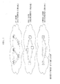
- FIG. 1 is a schematic view of such a network.
- This network is made up from a plurality of network layers, and it will be assumed that it comprises an IP layer, a TDM layer, and a Lambda layer.
- Each of the nodes in this network advertises its link state, which is made up from information such as IP address, maximum link band, usage band, and the like.
- a node which is to establish an LSP performs a computation for whether or not to establish a new TDM LSP or Lambda path for establishing an IP LSP, and, if such a TDM LSP or Lambda path is to be newly established, also performs a computation for determining upon which path the cost for establishing the LSP will be the least; and then it performs establishment of the LSP. Furthermore, when rearranging the path of some IP LSP, at the same time, computations are also made as to whether change of the path of the Lambda path of the layer below is necessary, and the like.
- FIG. 2 shows the situation when a multi layer network like the one described above is layered by being separated into cells and by being made into virtual nodes.
- layering is performed down to the third level (Level 3).
- Level 3 the third level
- FIG. 3 the situation is shown in which the entire network has been made into a virtual node.
- FIG. 4 is a schematic figure showing a node for this purpose.
- This node collects together link state information which gives the state of the present node and the states of links which are connected to the present node, and stores it in a link state database LSDB-L1.
- This link state information is advertised to other nodes via an advertisement section P.
- link state information both from the present node and also from other nodes which are included within the same virtual node is also advertised via the advertisement section P. From among the information which has arrived by advertisement at the advertisement section P, the Level 1 link state information is picked out and is stored in the link state database LSDB-L1.
- self node is disposed at a location where an interface with a virtual node is present (the nodes A, B, and C in FIG. 3 ), then self node comes to serve the function of a border node.
- LS abstraction section LS1 a node which has been chosen as a border node abstracts the link state information of the link state database LSDB-L1 to link state information for use at Level 2, and, along with storing this in a link state database LSDB-L2, also advertises it via the advertisement section P to the exterior of the virtual node as interface information for the virtual node.
- an LS abstraction section LS2 repeats the operation of obtaining link state information to be stored in a link state database LSDB-L3 from the link state information in the link state database LSDB-L2, for its level of the network.
- a switching capability of the interface of the virtual node of Level 2 is obtained by a switching capability allotment section (shown in the figure as a SC allotment section) SC of the LS abstraction station LS1. And there is provided a function of, along with storing these results in the link state database LSDB-L2, also advertising them via the advertisement section P to the exterior of the virtual node.
- FIG. 5 is a functional block diagram of the node at this time.
- a switching capability of the interface of the virtual node of Level 2 is obtained by a switching capability allotment section SC of the LS abstraction station LS1, and also the cost associated with going via self virtual node is computed by a cost computation section C.
- a cost computation section C the cost associated with going via self virtual node is computed by a cost computation section C.
- the LS abstraction section LS2 repeats the operation of obtaining link state information to be stored in the link state database LSDB-L3 from the link state information in the link state database LSDB-L2, for its level of the network.
- FIG. 6 is a functional block diagram of the node at this time.
- FIG. 7 shows the method of allotting switching capability to the interfaces of a virtual node.
- layers of the LSP which can be established between the interfaces via the interior of the virtual node are allotted to the interface as switching capability. Accordingly, switching capability is allocated dependent upon the output ports, as well as upon the input ports.
- FIG. 8 shows a method of allotting switching capability to the interfaces of a virtual node.
- a system is implemented of allotting the switching capabilities of the border routers within the cells at the interfaces of the virtual node as switching capability of the interfaces of the virtual node.
- the interfaces a1 and a2 have an LSC switching capability
- the interfaces b and c1 have a PSC switching capability
- the interface c2 has both an LSC + a PSC switching capability. In this manner, it is possible to reduce the volume of advertisements of switching capability of the virtual routers.
- FIG. 9 shows an outline of the LSP establishment cost in a virtual node network, in an eighth preferred embodiment of the present invention.
- the LSP establishment cost in a virtual node network is the cost of the links and the cost of going through the virtual nodes.
- Cost of establishing an LSP over a virtual network Sum of link costs + Sum of costs of passing via the virtual nodes .
- the layers of the LSPs which the virtual node can handle are shown by switching capability.
- Switching capability attributes are assigned to the interfaces of the virtual nodes.
- a cost of going through a virtual node is assigned for each switching capability which is possessed by the interfaces of the virtual node. This is because sometimes the cost is different, when going through the virtual node, between the case of going via an LSP on the IP layer and the case of going via an LSP on the Lambda layer. It is possible to determine upon which layer it is best to establish an LSP by performing comparison of the cost values for each of these layers.
- FIG. 10 shows a method of assigning the cost of going via a virtual node, in a ninth preferred embodiment of the present invention.
- the interior of the virtual node is constituted by a network, and the links which connect it to the exterior of the cell are taken as interfaces.
- the layers for which an LSP can be established between an input interface and an output interface of the virtual node are different for different ones of the interfaces.
- An example of this is shown in FIG. 10 , displayed as a matrix set up between the input and output interfaces.
- the path within the cell is also different, so that the corresponding cost incurred is also different. Accordingly, it is assumed that costs are allocated to the individual switching capabilities in the matrix between the input and output interfaces of the virtual node.
- the cost which is allotted to the individual switching capability in the matrix between the input and output interfaces of the virtual node is the cost of the path for which it is possible to establish an LSP at the minimum cost, as selected by a cost selection section from among the path candidates for which an LSP on the said switching capability layer can be established between these input and output interfaces.
- FIG. 11 shows the functional blocks of the layered network node at this time. The functional blocks of FIG. 11 are set up by further adding a cost selection section C to the functional blocks of FIG.
- switching capability is allotted by a switching capability allotment section SC
- computation and allotment of costs is added by the cost computation section C
- selection of the path over which an LSP can be established at the minimum cost is performed by a cost selection section S.
- the cost of establishing an LSP which has been set up in this manner is allotted as a cost of the interface of the virtual node.
- FIG. 12 shows a method of assigning the cost via a virtual node, in a tenth preferred embodiment of the present invention.
- the interior of the virtual node is constituted by a network, and the links which connect it to the exterior of the cell are taken as interfaces.
- the layers for which an LSP can be established between an input interface and an output interface of the virtual node are different for different ones of the interfaces.
- An example of this is shown in FIG. 10 , displayed as a matrix set up between the input and output interfaces.
- the path within the cell is also different, so that the corresponding cost incurred is also different. Accordingly, costs are individually allocated to the switching capabilities in the matrix between the input and output interfaces of the virtual node.
- the cost which is allotted to the individual switching capability in the matrix between the input and output interfaces of the virtual node is the cost of establishing the LSP whose path has the minimum number of hops upon the said layer which can be established between the said combination of input interface and output interface, and, if a plurality of such paths of the minimum number of hops exist, is the minimum cost from among the candidates.
- FIG. 13 shows a method of assigning costs to a node in an eleventh preferred embodiment of the present invention.
- the cost of a path is obtained by adding a node cost to a link cost.
- the cost of going through the node is determined by the number of interfaces which are possessed by that node.
- the cost of passing through the node upon any layer is taken as the reciprocal of the number, among the interfaces which are endowed with the switching capability of that layer, of the ones which are currently unused.
- FIG. 14 shows a method of assigning costs to a node in a twelfth preferred embodiment of the present invention.
- the cost of a path is obtained by adding a node cost to a link cost.
- the cost of going through the node is determined by the number of interfaces which are possessed by that node.
- the cost of passing through the node upon any layer is taken as being the number, among the interfaces which are endowed with the switching capability of that layer, of the ones which are currently being used, divided by the total number thereof.
- FIG. 15 shows a method of assigning a cost to passing through a virtual node in a thirteenth preferred embodiment of the present invention.
- a cost of passing through the virtual node is not allocated to each interface which is possessed by the virtual node; rather, it is allocated as a single cost for them all.
- the method of performing this allotment is to take this single cost as being the reciprocal of the total number of unused ones among the interfaces which are endowed with the switching capability of this layer and which the nodes which are included in self virtual node are endowed with.
- FIG. 16 shows a method of assigning a cost to passing through a virtual node.
- a cost of passing through the virtual node is not allocated to each interface which is possessed by the virtual node; rather, it is allocated as a single cost for them all.
- the method of performing this allotment is to take this single cost as being the number, among the interfaces which are endowed with the switching capability of that layer and which the nodes which are included in self virtual node are endowed with, of the ones which are currently being used, divided by the total number thereof.
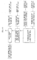
- FIG. 17 shows a path selection sequence of a seventeenth preferred embodiment of the present invention.
- the network range for performing path selection is determined. If, among the cells on the lowest level, destination nodes are present among the cells to which the source nodes belong, the path selection is performed from among these cells. If no destination node is present among these cells, the cells which include a source node are picked out from the cells of the next higher level, and an investigation is performed as to whether or not a destination node is present among these cells. If a destination node is present among these cells, then path selection is performed from among these cells; but if no destination node is present among these cells, then, in the same manner as before, an investigation is performed with the cells on the next higher level. This series of investigations is repeated until a destination node comes to light.
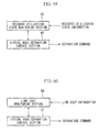
- FIG. 18 shows the functional blocks of the layered network node in this case.
- the functional blocks of FIG. 18 result from the addition of an L1 path selection section RS1, an L2 path selection section RS2, and an L3 path selection section RS3 to the functional blocks which were shown in FIG. 11 .
- FIG. 19 shows the sequence of the eighteenth preferred embodiment of the present invention.
- the network range for performing path selection is determined.
- a check is made to determine whether or not, among the cells at the topmost level, there exists a cell which includes both a source node and a destination node. If one such cell exists, then, in the same manner, a check is made to determine whether or not, for the network within this cell, there exists a cell which includes both a source node and a destination node, and this series of checks is repeated until the source node and the destination node come to be included within different cells. When it has been checked that the source node and the destination node are included within different cells, the network which includes these cells is set as the range for performing path selection.
- path selection of the virtual node network is performed by the path selection section of the said level.
- path selection of the virtual node network is performed by the path selection section of the said level in the same manner as within this cell. It becomes possible to determine upon the path from the source node to the destination node by repeating this path selection down to the lowest level.
- the functional blocks of the layered network node at this time are shown in FIG. 18 .
- FIG. 20 shows a network management system according to a nineteenth preferred embodiment of the present invention.
- a method has been conceived of undertaking the path selection computation for the internal network by a node, or by a virtual node, which corresponds to the input-output interfaces of the virtual node which are already decided upon.
- FIG. 21 shows a network management system according to a twentieth preferred embodiment of the present invention.
- FIG. 22 shows a link bundling system according to a twenty-first preferred embodiment of the present invention.
- the network is divided up into a plurality of cells, and, when these are defined as virtual nodes, the virtual nodes come to be connected together by the same number of links as the number of links by which the nodes themselves are connected within the cells.
- the virtualization of this network is performed by a hierarchical structure, a large number of links come to connect between these virtual nodes. In this case, when advertisement of the link states between the virtual nodes is considered, increase of the number of links is believed to entail increase of the number of link state advertisements.
- the cost which is allotted to the interfaces is considered as a method of advertising the interfaces which are connected together by self virtual link.
- FIG. 23 shows a link bundling system according to a twenty-second preferred embodiment of the present invention.
- the network is divided up into a plurality of cells, and, when these are defined as virtual nodes, the virtual nodes come to be connected together by the same number of links as the number of links by which the nodes themselves are connected within the cells.
- the virtualization of this network is performed by a hierarchical structure, a large number of links come to connect between these virtual nodes. In this case, when advertisement of the link states between the virtual nodes is considered, increase of the number of links is believed to entail increase of the number of link state advertisements.
- this twenty-third preferred embodiment of the present invention is a program which is distinguished in that, by being installed upon a computer device, it causes that computer device to execute procedures of, when establishing a LSP on any layer of the network which includes the layered network node of this preferred embodiment of the present invention, when selecting a path from a source node to a destination node: making a decision, by referring to said link state database of the lowest level 1, as to whether or not, among the said virtual nodes of level 1, the destination node is present within the same virtual node which includes the source node; and, if the destination node is not present within any same virtual node as the source node, making a decision, by referring to said link state database of the next higher level 2, as to whether or not the destination node is present in any of the virtual nodes of level 2 which include the said source node; and,
- this twenty-third preferred embodiment of the present invention is a program which is distinguished in that, by being installed upon a computer device, it causes that computer device to execute procedures of, when establishing a LSP on any layer of the network which includes the layered network node of this preferred embodiment of the present invention, when selecting a path from a source node to a destination node: making a decision, for a network which incorporates virtual nodes of a topmost level N, by referring to said link state database of said level N, as to whether or not the destination node is present within the same virtual node which includes the source node; and, if the destination node is indeed present within the same virtual node as the source node, making a decision, by referring to said link state database of the next lower level (N-1) than self virtual node, as to whether or not the source node and the destination node are present in the same virtual node in the network of the next lower level (N-1) within self virtual node; and, by repeating this decision until the source node and the destination no
- FIG. 24 is a figure showing how the network is divided up into cells, is made into virtual nodes, and is layered.
- FIG. 25 is a figure showing the topology of the layered network.
- the layered network of this preferred embodiment of the present invention is a layered network in which the nodes which make up the network are divided up into cells (the portions surrounded by the broken lines) which consist of one or a plurality of nodes, and these cells are defined as virtual nodes of level 1, so that these virtual nodes of level 1 constitute the virtual network of level 1; and, as shown in Level 2 of FIG. 24 , the said virtual nodes of level 1 which constitute the virtual network of level 1 are furthermore divided into cells which are made up from one or a plurality of said virtual nodes and constitute virtual nodes of level 2, so that the layered network such as that shown in FIG.
- the 24 is constituted by building up a 1 to N level virtual network by repeating this type of operation of dividing into cells and making into virtual nodes once or a plurality N of times, and if, in the said layered network, a link exists which connects between different virtual nodes of the same level or of different levels, then, when the node which corresponds to the point of contact between the interior of the virtual node upon this link and the exterior is defined as an interface, and the virtual node to which said interface is related on the highest level is at the level M ( ⁇ N), said interface is defined as serving as a plurality of layered interfaces from level 1 to M. In the example shown in FIG. 24 , the layering continues down to Level 3.
- nodes which make up the layered network of this preferred embodiment of the present invention may be divided up into nodes which correspond to said interfaces, and nodes which do not correspond to said interfaces.
- the nodes which correspond to said interfaces will be termed border nodes, while the nodes which do not correspond to said interfaces will be termed non border nodes.
- the border nodes are also capable of fulfilling the functions of the non border nodes, the following explanation of the border nodes will be made with emphasis upon their functions which are different from those of the non border nodes, in order to make the explanation easier to understand.
- FIG. 25 shows a topology of this type of layered network.
- the white circles in FIG. 25 are non border nodes upon level 1.
- the hatched circles in FIG. 25 are border nodes of level 1, and these correspond to interfaces. Although these interfaces are border nodes of level 1, they also belong to level 2.
- the solid black circles in FIG. 25 are border nodes of level 1, and these also correspond to interfaces. Although these interfaces are border nodes of level 1, they also belong to level 2 and to level 3.
- the circles shown by thin solid lines in FIG. 25 are virtual nodes of level 2, while the circles shown by thick solid lines are virtual nodes of level 3.
- the straight fine solid lines are links of level 1, while the straight fine broken lines are links of level 2. Furthermore, the thick broken lines are links of level 3.
- the twenty-fourth preferred embodiment of the present invention is a preferred embodiment which is related to a non border node (shown as a white circle).
- the structure of such a non border node is shown in FIG. 26 .
- This non border node according to the twenty-fourth preferred embodiment of the present invention is characterized by comprising: an advertisement section 1 which advertises information about the links which are connected to self node and link cost information about said links to the other nodes within self virtual node; a retention section for information within self virtual node which receives advertisements of link information about links within self virtual node and link cost information about said links from other nodes within self virtual node, and stores said information; and a retention section 3 for information within other virtual nodes, which receives advertisements of link information about links between the border nodes which correspond to interfaces of self virtual node and the border nodes which correspond to interfaces of a virtual node on a higher level than self virtual node, and link cost information about said links, from the border nodes which correspond to the interfaces, and stores said information
- this border node is a node which has both the function of an interface and also the same function as a non border node, it performs advertisements just like said two elements together.
- this non border node comprises an IP address notification section 4 which transmits its own IP address to a border node which corresponds to an interface of self virtual node, and the retention section 3 for information within other virtual nodes 3 stores external IP address group information, which is information about the IP addresses of other nodes which belong to virtual nodes other than self virtual node and information about the virtual nodes to which said IP addresses belong, which has been transmitted from the border nodes which correspond to said interfaces.
- FIG. 27 is a block structure diagram of this border node according to the twenty-fourth preferred embodiment of the present invention.
- an IP address information collection section 14 which gathers together and stores IP address information from other nodes within self virtual node
- an external advertisement section 15 which advertises to an other node which corresponds with an interface with an other virtual node IP address information which has been gathered together by this IP address information collection section 14, and a retention section 16 for IP address groups within other virtual nodes which stores the IP addresses of other nodes which belong to virtual nodes other than self virtual node and external IP address group information, which is information about the virtual nodes to which said IP addresses belong, which has been advertised from border nodes which correspond to interfaces with other virtual nodes, and transmits it to other nodes within self virtual node.
- FIG. 28 is a figure for explaining this path searching method according to the twenty-fourth preferred embodiment.
- the source node for path establishment shown in FIG. 28 as shown in FIG.
- a destination node position search section 5 which specifies, from the IP address of the destination node for path establishment, a virtual node to which said destination node belongs, based upon the external IP address group information; and a path search section 6 which searches out a path to a border node which corresponds with the interface to the virtual node to which said destination node which has been specified by the destination node position search section 5 belongs, based upon information about links between the border node which corresponds to the interface of self virtual node and the border node which corresponds with the interface of the virtual node of a higher level than self virtual node, and link cost information about said links.
- the destination node position search section 5 searches out the virtual node to which the destination node belongs, based upon the external IP address group information which has been stored in the retention section 3 for information within other virtual nodes.
- the path search section 6 searches out a path to the border node with said virtual node, based upon the link information and the link cost information which has been stored in the retention section 3 for information within other virtual nodes.
- the source node does not perform a search as far as a detailed path within the virtual node to which the destination node belongs, provided that it does search out a path to the border node of the virtual node to which the destination node belongs, no evil effect will occur and cause a problem in practice, even if path searching to the destination node from said border node is delegated to said border node.
- FIG. 29 is a block structure diagram of this non border node according to the twenty-fifth preferred embodiment.
- This non border node according to the twenty-fifth preferred embodiment of the present invention is basically the same in structure as the non border node of the twenty-fourth preferred embodiment of the present invention shown in FIG. 26 .
- the features by which it differs are that an external IP address group information capture section 7 is additionally provided, and that the retention section 3 for information within other virtual nodes does not store the external IP address group information.
- the external IP address group information capture section 7 requests and obtains the IP addresses of other nodes which belong to virtual nodes other than self virtual node, and external IP address group information, which is information about the virtual nodes to which said IP addresses belong, from border nodes which correspond to said interface.
- FIG. 30 is a block structure diagram of an essential portion of this border node according to the twenty-fifth preferred embodiment.
- An IP address group information retention section 17 within an other virtual node of this border node according to the twenty-fifth preferred embodiment of the present invention stores the IP addresses of other nodes which belong to virtual nodes other than self virtual node, and external IP address group information, which is information about the virtual nodes to which said IP addresses belong, which has been advertised from a border node which corresponds to an interface with an other virtual node, and offers this external IP address group information which has been stored to said other nodes, according to requests from said other nodes.
- This twenty-fifth preferred embodiment of the present invention is applied in the case of using a network environment in which the destination node shifts frequently.
- a necessity arises for the border node to perform transmission of update information to the source node each time the destination node shifts, since, with this twenty-fifth preferred embodiment, an offer of information is requested from the source node to the border node only when the source node performs path searching, the border node does not need to perform transmission of update information to the source node each time the destination node shifts, so that it is possible to reduce the amount of processing which is required, by comparison with the twenty-fourth preferred embodiment of the present invention described above.
- FIG. 31 is a block structure diagram of this non border node according to the twenty-sixth preferred embodiment.
- This non border node according to the twenty-sixth preferred embodiment of the present invention comprises: an IP address and link cost notification section 8 which transmits the IP address of self node and link cost information between self node and the border node which corresponds to the interface of self virtual node, and link cost information, to said border node which corresponds to said interface; and an external IP address group and link cost information retention section 9 which stores the IP addresses of other nodes which belong to virtual nodes other than self virtual node and external IP address group information, which is information about the virtual nodes to which said IP addresses belong, which has been transmitted from border nodes which correspond to said interface, and link cost information from the border node which corresponds to said interface to said other node, in correspondence with the IP addresses of said other nodes.
- the link cost information is transmitted to the border node by the IP address and link cost notification section, along with the IP address of self node 8, as far as said border node.
- the link information and the external IP address group and link cost information for within other virtual nodes are transmitted from the border node, and they are respectively stored in the retention section 3 for information within other virtual nodes and in the external address group and link cost information retention section 9.
- the destination node position search section 5 searches out the virtual node to which the destination node belongs, based upon the external IP address group information which has been stored in the external address group and link cost information retention section 9.
- the path search section 6 searches out a path to the border node with said virtual node, based upon the link cost information which is stored in the external address group and link cost information retention section 9.
- FIG. 32 is a block structure diagram of this border node according to the twenty-sixth preferred embodiment of the present invention. As shown in FIG. 32
- the border node according to the twenty-sixth preferred embodiment of the present invention comprises: an IP address and link cost information collection section 18 which gathers together and stores IP address information from other nodes within self virtual node and link cost information between said other node and self node; an external advertisement section 19 which advertises to a border node which corresponds to an interface with an other virtual node the IP address information and link cost information which have been gathered together by this IP address and link cost information collection section 18; and an external IP address group and link cost information collection section 20 and an internal advertisement section 21 which stores external IP address group information, which is information about the IP addresses of other nodes which belong to virtual nodes other than self virtual node and information about the virtual nodes to which said IP addresses belong, which has been advertised from the border nodes which correspond to said interface of the other virtual node, and link cost information from the border node which corresponds with said interface with said other virtual node to said other node, in correspondence with the IP addresses of said other nodes, and transmits it to other nodes within self virtual node.
- the source node cannot perform its searching as far as a detailed path within the virtual node to which the destination node belongs, nevertheless the source node is able to search out the path up to the destination node for which the link cost is the least, provided that it can search out a path as far as the border node of the virtual node to which the destination node belongs, since the link cost from said border node up to the destination node is known.
- FIG. 33 is a block structure diagram of this non border node according to the twenty-seventh preferred embodiment.
- this non border node according to the twenty-seventh preferred embodiment of the present invention does not store external IP address group and link cost information, but differs in that, when performing path computation, an external IP address group and link cost information capture section 10 requests and obtains that information from the border node.
- FIG. 34 is a block structure diagram of an essential portion of this border node according to the twenty-seventh preferred embodiment.
- FIG. 34 is a block structure diagram of an essential portion of this border node according to the twenty-seventh preferred embodiment.
- this border node differs in that an external IP address group and link cost information collection section 22, along with storing external IP address group information, which is information about the IP addresses of other nodes which belong to virtual nodes other than self virtual node and information about the virtual nodes to which said IP addresses belong, which has been advertised from the border nodes which correspond to said interface of the other virtual node, and link cost information from the border node which corresponds with said interface with said other virtual node to said other node, in correspondence with the IP addresses of said other nodes, also, upon a request from an other node, offers to said other node said external IP address group information and link cost information which has been stored.
- external IP address group and link cost information which is information about the IP addresses of other nodes which belong to virtual nodes other than self virtual node and information about the virtual nodes to which said IP addresses belong, which has been advertised from the border nodes which correspond to said interface of the other virtual node, and link cost information from the border node which corresponds with said interface with said other virtual node to said other node
- the source node requests an offer of information from a border node, it is possible to obtain information about the virtual node to which said destination belongs and the link cost information from said border node up to said destination node by performing designation of the IP address of the destination node, it is possible to obtain the minimum amount of information which is required, and accordingly it is possible to alleviate the amount of processing upon the border node and upon the non border node which becomes the source node.
- this twenty-seventh preferred embodiment of the present invention is applied in the case of utilizing a network environment in which the destination node changes frequently.
- the necessity arises for the border node to perform transmission of information which has been updated to the source node each time the destination node shifts by contrast, in this twenty-seventh preferred embodiment of the present invention, since an offer of information is only requested from the source node to the border node when the source node perform path searching, therefore it is not necessary for the border node to perform transmission of update information to the source node every time the destination node shifts, so that it is possible to reduce the amount of processing, as compared with the twenty-sixth preferred embodiment of the present invention.
- FIG. 35 is a block structure diagram of an essential portion of a non border node according to this twenty-eighth preferred embodiment of the present invention.
- This non border node according to this twenty-eighth preferred embodiment of the present invention as shown in FIG. 35 , comprises a reachability advertisement section 23 which dispatches a packet for checking reachability to a border node which corresponds to an interface of self virtual node.
- the non border nodes perform transmission of reachability to specified border nodes
- the non border nodes perform advertisement of reachability to non specified border nodes within self virtual node.
- IP headers for advertisement are assigned to the reachability advertisement packets, and these are set up so as to be destined for non specified border nodes. Furthermore, by writing the IP addresses of the non border nodes which are the sources of dispatch into said IP headers, it is possible to check the reachability corresponding to the IP addresses in the border nodes which receive said IP packets for advertisement, since it is possible to specify their sources of dispatch.
- FIG. 36 is a block structure diagram of an essential portion of this border node according to the twenty-eighth preferred embodiment.
- This border node according to the twenty-eighth preferred embodiment of the present invention comprises a reception section 24 for reachability advertisement packets which receives packets for checking reachability from other nodes within self virtual node, an internal IP address group information creation section 25 which summarizes the IP addresses of said packets which have been received and creates internal IP address group information which is related to nodes within self virtual node, an information synchronization section 26 which converts said internal IP address group information which has thus been created with other border nodes within self virtual node, compensates them so that they are neither too great nor too small, and synchronizes them as internal IP address group information which has been unified for self virtual node, and an external advertisement section 27 which advertises this internal IP address group information which has thus been unified by said information synchronization section 26 to the border node
- FIG. 37 shows the general concept of operation of this twenty-eighth preferred embodiment of the present invention.
- a non border node (shown by the white circle) emits a packet for advertising reachability.
- a border node (shown by hatching) which has received this packet establishes synchronization of the internal IP address group information between border nodes (as shown by the broken line), and, after having created unified internal IP address group information, advertises said internal IP address group information to the border node of the other virtual node.
- the external advertisement section 27 comprises an advertisement implementation node determination section 28 which decides whether or not an advertisement path is available from an other border node within self virtual node to the border node which corresponds to the interface of the other virtual node, and, when the result of this decision is "yes", performs advertisement by one or another advertisement path of self node or of said other border node to the border node which corresponds to the interface of said other virtual node.
- FIG. 40 is a block structure diagram of an essential portion of a border node according to this twenty-ninth preferred embodiment of the present invention.
- This border node comprises: a reception section 24 for reachability advertisement packets which receives packets for checking reachability from other nodes within self virtual node, an internal IP address group information creation section 25 which summarizes the IP addresses of said packets which have been received and creates internal IP address group information which is related to nodes within self virtual node, and an external advertisement section 27 which advertises this internal IP address group information which has thus been created to the border node which corresponds to the interface with the other virtual node.
- the information synchronization section 26 of the twenty-eighth preferred embodiment of the present invention has been eliminated.
- it is ventured to permit disagreement of the internal IP address group information between border nodes within the same virtual node.
- the reachability with respect to some border node may differ even for border nodes within the same virtual node, by performing advertisement of this kind of distinction, it becomes possible to recognize the border nodes through which it is not possible to establish a path by path computation.
- FIG. 41 is a block structure diagram of an essential portion of a non border node according to this thirtieth preferred embodiment of the present invention.
- This non border node according to the thirtieth preferred embodiment of the present invention comprises a link cost computation section 30 which computes individual link costs for a plurality of border nodes which correspond to said interface of self virtual node. In other words, it computes a link cost to each border node within self virtual node, based upon the information which has been stored in the retention section 2 for information within self virtual node.
- the IP address notification section 29 transmits its own IP address by emitting a packet for checking reachability to the border node which corresponds to said interface for which, according to the computation results of this link cost computation section 30, the link cost is the least.
- the border node is able to ascertain only the IP address of the non border node for which the link cost is the least, and accordingly it is possible to reduce the amount of information which needs to be summarized and advertised.
- FIG. 41 is a block structure diagram of an essential portion of a non border node according to this thirty-first preferred embodiment of the present invention, and is common with the thirtieth preferred embodiment.
- This non border node according to the thirty-first preferred embodiment of the present invention comprises a link cost computation section 30 which computes individual link costs for a plurality of border nodes which correspond to said interface of self virtual node. In other words, it computes a link cost to each border node within self virtual node, based upon the information which has been stored in the retention section 2 for information within self virtual node.
- the IP address notification section 29 transmits its own IP address by emitting a packet for checking reachability to the border node which corresponds to said interface for which, according to the computation results of this link cost computation section 30, the link cost is the n-th least in order (where n is a natural number).
- the border node is able to ascertain only the IP addresses of the minority of non border nodes for which the link costs are the least in order, and accordingly it is possible to reduce the amount of information which needs to be summarized and advertised.
- the amount of information which needs to be summarized and advertised becomes greater, by appropriately varying the value of the natural number n, it is easily possible to adjust the amount of information to an amount which the border nodes can most easily deal with in every possible set of circumstances.
- FIG. 41 is a block structure diagram of an essential portion of a non border node according to this thirty-second preferred embodiment of the present invention, and is common with the thirtieth and the thirty-first preferred embodiments.
- This non border node according to the thirty-second preferred embodiment of the present invention as shown in FIG. 41 , comprises a link cost computation section 30 which computes individual link costs for a plurality of border nodes which correspond to said interface of self virtual node. In other words, it computes a link cost to each border node within self virtual node, based upon the information which has been stored in the retention section 2 for information within self virtual node.
- the IP address notification section 29 transmits its own IP address and summarized link cost information to the border node which corresponds to said interface for which, according to the computation results of this link cost computation section 30, the link cost is the n-th least in order (where n is a natural number), by emitting a packet for checking reachability which includes information about said number in order.
- the border node is able to ascertain only the IP addresses of the minority of non border nodes for which the link costs are the least in order, and accordingly it is possible to reduce the amount of information which needs to be summarized and advertised.
- this border node comprises: a reception section 32 for packets for checking reachability, which receives packets for checking reachability which include information to the effect that, from the other nodes within self virtual node, self node has the n-th smallest link cost with respect to said other nodes; an internal IP address group information creation section 33 which summarizes for each of said n values the IP addresses of the packets which have been received by said reception section 32 for packets for checking reachability, and creates internal IP address group information related to nodes within self virtual node; and an external advertisement section 27 which advertises this internal IP address group information which has thus been created by said internal IP address group information creation section 33 to the border node which corresponds to the interface with the other virtual node.
- FIG. 43 is a block structure diagram of an essential portion of a non border node according to this thirty-third preferred embodiment of the present invention.
- FIG. 44 is a general conceptual figure of the scope of level 1 of the non border node according to this thirty-third preferred embodiment of the present invention. This non border node according to the thirty-third preferred embodiment of the present invention, as shown in FIG.
- an advertisement section 1 which advertises information about links which are connected to this link and link cost information about said links to the other nodes within self virtual node
- a retention section 2 for information within self virtual node which receives information about links within self virtual node and link information about the cost of said links from other nodes within self virtual node, and stores said information.
- a non border node (shown by the white circle) only stores information relating to the situation within self virtual node. By doing this, it is possible to reduce the amount of data which must be handled.
- a capture section 31 for information within other virtual nodes which, before performing the path computation, requests and obtains, from a border node which corresponds to said interface, link information for between a border node which corresponds to an interface with self virtual node and a border node which corresponds to an interface with a virtual node upon a higher level, and link cost information for said link.
- the amount of information is reduced by, normally, only handling information within self virtual node, while, according to requirements, receiving information about the situation within other virtual nodes, so that it is possible to reduce the amount of information which must be handled within a fixed time.
- FIG. 45 is a block structure diagram of an essential portion of a border node according to this thirty-fourth preferred embodiment of the present invention.
- FIG. 46 is a general conceptual figure of the scope of level 2 of the border node according to this thirty-fourth preferred embodiment. This non border node according to the thirty-fourth preferred embodiment of the present invention, as shown in FIG.
- an advertisement section 34 which advertises to border nodes which correspond to interfaces upon the same level as self node link information about links upon the same level at self node which have been connected to self node, and link cost information for said links; and a same level border node information retention section 35 which receives, from border nodes which correspond to interfaces upon the same level as self node, advertisements of link information for links between self node and border nodes which correspond to interfaces upon the same level as self node, and link cost information for said links, and stores said information.
- the border nodes shown by hatching
- the border nodes only store information between themselves and border nodes upon the same level as themselves. Due to this, it is possible to reduce the amount of data which must be handled.
- a capture section 36 for information within virtual nodes on higher levels, which, before the path computation, requests and receives link information about links with a border node which corresponds to an interface on a higher level than self node, and link cost information about said links, from the border node which corresponds to said interface.
- FIGS. 47 and 48 are figures for explanation of this path search method according to this thirty-fifth preferred embodiment of the present invention.
- the non border node according to the thirty-third preferred embodiment of the present invention which was explained with reference to FIG. 43 is employed. In other words, referring to the FIG.
- a capture section 31 for information within other virtual nodes which requests and obtains link information for links within said virtual node and link cost information about said links from the border node #7 which corresponds to the interface of the virtual node to which the destination node #8 belongs, and a path search section which, in addition to the path which has already been searched out to the border node #7 which corresponds to the interface with the virtual node to which the destination node #8 belongs, based upon said link information and said link cost information which have been obtained by said capture section 31 for information within other virtual nodes, as shown in FIG. 48 , searches out a path from the border node #7 which corresponds to said interface to the destination node #8.
- the capture section 31 for information within other virtual nodes requests and obtains link information for links within said virtual node and link cost information about said links from the border node #5 or the border node #6, and, based upon said link information and said link cost information which it has received, searches out a path from self node within the virtual node to which border node #5 and the border node #6 belong.
- the source node #1 is able to perform detailed path searching by obtaining information within any one of the virtual nodes.
- FIG. 48 is a figure for explanation of this path search method according to this thirty-sixth preferred embodiment of the present invention, and is common with the thirty-fifth preferred embodiment.
- FIG. 49 is a figure showing the overall block structure of a non border node according to this thirty-sixth preferred embodiment of the present invention.
- FIG. 50 is a sequence diagram for explanation of the path search method according to this thirty-sixth preferred embodiment of the present invention.
- the source node #1 for path establishment comprises a destination node position search section 5 which specifies the virtual node #B to which said destination node #8 belongs from the IP address of the destination node #8 for path establishment, based upon the external IP address group information, and a path search section 37 which, based upon link information for links between the border node #2 which corresponds to the interface with self virtual node and the border node #4 which corresponds to an interface with a virtual node which is on a higher level than self virtual node, and upon link cost information for said links, notifies to the destination node #8 for path establishment information which specifies on which level is the virtual node #A on the topmost level for which path computation is possible from self node to the border node #4 which corresponds to the interface, and the results of searching out paths from self node to the border node #4 which corresponds to said interface in order up to that one for which the link cost is the
- the source node #1 specifies the position of the destination node #8 with the destination node position search section 5 (in the step 1), searches out a path to the virtual nodes #4 and #9 upon the topmost level for which computation by the path search section 37 is possible (in the step 2), and notifies these search results to the destination node #8 (in the step 3).
- a path to the virtual nodes #4 and #9 is searched out by the path search section 37 (in the step 4), and, by adding the path to the virtual nodes #4 and #9 from the source node #1 which has been notified from the source node #1, selects the path for which the link cost becomes the minimum (in the step 5), and notifies these selection results to the source node #1 (in the step 6).
- an LSP to the destination node #8 is established based upon this notification (in the step 7). It should be understood that this establishment of an LSP may also be performed from the destination node #8 (in the step 8). If the LSP is to be established from the destination node #8, it is possible to eliminate the step 6.
- the beneficial feature of this path search method is that, in a case such as when, for example, it is necessary to establish a large number of LSPs from a single source node to a large number of destination nodes all together, and it is difficult for the side of the source node to bear the entire burden which is required to establish the LSPs, by sharing out the burden which is required for the path searching to the sides of the destination nodes, it is thereby possible to alleviate the burden which is imposed upon the source node by this path searching procedure.
- FIGS. 51 through 53 are figures for explanation of the definition of a border node according to this thirty-seventh preferred embodiment of the present invention, and is common with the thirty-seventh preferred embodiment.
- FIG. 53 is a block structural diagram of an essential portion of a node according to this thirty-seventh preferred embodiment of the present invention. Since the layered network according to this thirty-seventh preferred embodiment of the present invention is implemented as a multi layer network, Lambda paths, TDM-LSPs, and packet paths are mixed together within links which are established between the virtual nodes.
- This border node within a virtual node which has been created, exercises autonomously a function as a border node in correspondence with the layer of a LSP which has been established between virtual nodes which are adjacent.
- a LSP which has been established between virtual nodes which are adjacent.
- FIG. 51 it is a Lambda path upon the Lambda layer which is established between virtual nodes which are adjacent. Accordingly, an optical cross connect device which corresponds to the node 2 is established as a border node.
- FIG. 52 it is a packet path upon the IP layer which is established between virtual nodes which are adjacent. Accordingly, a router which corresponds to the node 1 is established as a border node. In this manner, the termination point of an LSP between virtual nodes which are adjacent is established as a border node of the virtual node.
- this termination point decision section 38 refers to the link information which has been stored in the retention section 3 for information within other virtual nodes and makes a decision as to whether or not a link which connects self virtual node and an other virtual node is connected to self node; if, according to the result of this decision, the link which connects self virtual node and an other virtual node is connected to self node, makes a decision as to whether or not self node corresponds to the termination point for the layer of the LSP which has been established upon said link; and if, according to the result of this decision, self node corresponds to said termination point, recognizes that self node is a border node which corresponds to said interface, and issues a command to the interface functional section 39 to exercise a function which corresponds to the interface.
- FIG. 54 is a figure for explanation of a method of dividing up into virtual nodes according to this thirty-eighth preferred embodiment of the present invention.
- FIG. 55 is a block structural diagram of an essential portion of a node according to this thirty-eighth preferred embodiment of the present invention.
- This node according to this thirty-eighth preferred embodiment of the present invention, as shown in FIG. 55 , comprises a resource utilization state monitoring section 40 which observes the state of utilization of resources related to self node, and if, based upon the results of observation by this resource utilization state monitoring section 40, availability of resources for use in data transmission to other nodes within self virtual node disappears, and self node corresponds to said interface, outputs a command to the node functional section 41, and, along with exercising a function as a node which belongs to an other virtual node of level 1 to which self node has been connected, also updates the information about the virtual node to which self node belongs, which has been stored in the virtual node information retention section 42, along with change of said associated virtual node.
- the virtual node information retention section 42 along with advertising the details of updates, also, when such an advertisement has been received from an other node, updates the information for the virtual note to which self node belongs, based upon said advertisement.
- FIG. 54 is a figure for explanation of a method of dividing up into virtual nodes according to this thirty-ninth preferred embodiment of the present invention, and is common with the thirty-eighth preferred embodiment.
- FIG. 56 is a block structural diagram of an essential portion of a node according to this thirty-ninth preferred embodiment of the present invention.
- This node according to this thirty-ninth preferred embodiment of the present invention, as shown in FIG. 56 , comprises a link cost monitoring section 43 which observes the link cost related to self node, and if, based upon the results of observation by this link cost monitoring section 43, the cost of links for use in data transmission to other nodes within self virtual node becomes greater than a threshold value, and self node corresponds to said interface, outputs a command to the node functional section 44, and, along with exercising a function as a node which belongs to an other virtual node of level 1 to which self node has been connected, also updates the information about the virtual node to which self node belongs, which has been stored in the virtual node information retention section 42, along with change of said associated virtual node.
- the virtual node information retention section 42 along with advertising the details of these updates, also, when such an advertisement has been received from an other node, updates the information for the virtual note to which self node belongs, based upon said advertisement.
- FIG. 57 is a block structural diagram of an essential portion of self node according to the fortieth preferred embodiment of the present invention.
- the node according to the fortieth preferred embodiment of the present invention is a device which combines the nodes of the nodes according to the thirty-eighth and the thirty-ninth preferred embodiments of the present invention.
- it commands the node functional section 45 to initiate its own functions by referring to both the resource utilization state information due to the resource utilization state monitoring section 40 and also the link cost information within the virtual node due to the link cost monitoring section 43.
- it is possible to implement division into virtual nodes while accruing the benefits of both the thirty-eighth preferred embodiment and also the thirty-ninth preferred embodiment of the present invention.
- the forty-first preferred embodiment of the present invention is a preferred embodiment of a network control device which controls the layered network all together.
- the explanation will be made in terms of only one network control device being provided to a layered network, if the following explanation is applied to only a part of the layered network, it would also be possible to explain in the same manner a mode of implementation which controlled the entire layered network using a plurality of network control devices.
- the establishment of a border node will be explained with reference to FIGS. 51, 52 , and 58 .
- FIGS. 51 and 52 are figures for explanation of the definition of a border node.
- FIG. 58 is a block structure diagram showing an essential portion of the network control device according to the forty-first preferred embodiment of the present invention. Since the layered network of this forty-first preferred embodiment is implemented as a multi layer network, Lambda paths, TDM-LSPs, and packet paths are mixed together within links which are established between the virtual nodes.
- the network control device establishes a border node corresponding to the layer of an LSP which has been established between adjacent virtual nodes within a virtual node which has been created.
- a border node corresponding to the layer of an LSP which has been established between adjacent virtual nodes within a virtual node which has been created.
- FIG. 51 it is a Lambda path upon the Lambda layer which is established between adjacent virtual nodes. Accordingly, an optical cross connect device which corresponds to a node 2 is established as a border node.
- FIG. 52 it is a packet path upon the IP layer which is established between adjacent virtual nodes. Accordingly, a router which corresponds to a node 1 is established as a border node. In this manner, the termination point of an LSP between adjacent virtual nodes is established as a border node of self virtual node.
- a node type database 46 in which information related to the types of nodes which are provided within the network is accumulated.
- a border node establishment section 47 refers to self node type database 46, recognizes the types of the nodes within each virtual node, and determines upon a node to be established as a border node corresponding to the layer of a link between adjacent virtual nodes, and dispatches an establishment command for said node.
- the node which has received this establishment command recognizes itself as a border node, and accordingly exercises a function as a border node.
- FIG. 54 is a figure for explanation of the method of dividing up into virtual nodes of this forty-second preferred embodiment of the present invention, and is common with the thirty-eighth and the thirty-ninth preferred embodiments of the present invention.
- FIG. 59 is a block structure diagram showing an essential portion of the network control device according to this forty-second preferred embodiment of the present invention.
- the network control device comprises a resource utilization state monitoring section 48 which observes the resource utilization state of each node, and a virtual node separation control section 49 refers to the resource utilization state monitoring section 48, and commands each of the nodes to divide into new virtual nodes as required. In a node which has received this command, it renews the information about the virtual node to which it itself belongs, and then exercises a function as a node within the new virtual node.
- FIG. 54 is a figure for explanation of the method of dividing up into virtual nodes of this forty-third preferred embodiment of the present invention, and is common with the thirty-eighth, the thirty-ninth, and the forty-second preferred embodiments of the present invention.
- FIG. 60 is a block structure diagram showing an essential portion of the network control device according to this forty-third preferred embodiment of the present invention.
- the network control device comprises a link cost monitoring section 50 which observes the link cost of each node, and a virtual node separation control section 51 refers to the link cost monitoring section 50, and commands each of the nodes to divide into new virtual nodes as required. In a node which has received this command, it renews the information about the virtual node to which it itself belongs, and then exercises a function as a node within the new virtual node.
- the value of the threshold value may be taken as the link cost value of the virtual node for which the link cost is the least, so that the link cost of each virtual node remains constant.
- FIG. 61 is a block structure diagram showing an essential portion of this network control device according to the forty-fourth preferred embodiment of the present invention.
- This network control device according to the forty-fourth preferred embodiment of the present invention is a combination of the network control devices according to the forty-second and the forty-third preferred embodiments of the present invention.
- the virtual node separation control section 52 commands the separation into virtual nodes by referring to both of the resource utilization state information between the nodes which is produced by the resource utilization state monitoring section 48 and also to the link cost information within the virtual nodes which is produced by the link cost monitoring section 50. By doing this, it is possible to implement separation into virtual nodes while obtaining the benefits of both the forty-second preferred embodiment and also the forty-third preferred embodiment of the present invention.
Landscapes
- Engineering & Computer Science (AREA)
- Computer Networks & Wireless Communication (AREA)
- Signal Processing (AREA)
- Environmental & Geological Engineering (AREA)
- Data Exchanges In Wide-Area Networks (AREA)
Applications Claiming Priority (3)
| Application Number | Priority Date | Filing Date | Title |
|---|---|---|---|
| JP2002293679A JP3762348B2 (ja) | 2002-10-07 | 2002-10-07 | 階層化ネットワークノード並びにそのノードにより構成されたネットワーク |
| JP2003036801A JP3672557B2 (ja) | 2003-02-14 | 2003-02-14 | ノードおよび階層化ネットワーク |
| EP03103679A EP1411687A3 (de) | 2002-10-07 | 2003-10-03 | Geschichteter Netzwerkknoten |
Related Parent Applications (1)
| Application Number | Title | Priority Date | Filing Date |
|---|---|---|---|
| EP03103679.1 Division | 2003-10-03 |
Publications (1)
| Publication Number | Publication Date |
|---|---|
| EP2242218A1 true EP2242218A1 (de) | 2010-10-20 |
Family
ID=32044676
Family Applications (4)
| Application Number | Title | Priority Date | Filing Date |
|---|---|---|---|
| EP10170296A Withdrawn EP2242218A1 (de) | 2002-10-07 | 2003-10-03 | Geschichteter Netzwerkknoten |
| EP10170303A Withdrawn EP2242219A1 (de) | 2002-10-07 | 2003-10-03 | Geschichteter Netzwerkknoten |
| EP03103679A Withdrawn EP1411687A3 (de) | 2002-10-07 | 2003-10-03 | Geschichteter Netzwerkknoten |
| EP10170291A Withdrawn EP2242217A1 (de) | 2002-10-07 | 2003-10-03 | Geschichteter Netzwerkknoten |
Family Applications After (3)
| Application Number | Title | Priority Date | Filing Date |
|---|---|---|---|
| EP10170303A Withdrawn EP2242219A1 (de) | 2002-10-07 | 2003-10-03 | Geschichteter Netzwerkknoten |
| EP03103679A Withdrawn EP1411687A3 (de) | 2002-10-07 | 2003-10-03 | Geschichteter Netzwerkknoten |
| EP10170291A Withdrawn EP2242217A1 (de) | 2002-10-07 | 2003-10-03 | Geschichteter Netzwerkknoten |
Country Status (4)
| Country | Link |
|---|---|
| US (1) | US7545829B2 (de) |
| EP (4) | EP2242218A1 (de) |
| CN (1) | CN100459534C (de) |
| CA (1) | CA2444363C (de) |
Cited By (1)
| Publication number | Priority date | Publication date | Assignee | Title |
|---|---|---|---|---|
| CN104135380A (zh) * | 2014-03-26 | 2014-11-05 | 中国通信建设集团设计院有限公司 | 分层网络的风险分析方法和装置 |
Families Citing this family (49)
| Publication number | Priority date | Publication date | Assignee | Title |
|---|---|---|---|---|
| US7889675B2 (en) * | 2003-01-31 | 2011-02-15 | Tellabs Operations, Inc. | Method and system for multi-layer network routing |
| EP1470679B1 (de) | 2002-02-01 | 2010-11-24 | Tellabs Operations, Inc. | Verfahren und vorrichtung für ein mehrschichtiges netzwerk in sonet/sdh |
| US7983182B2 (en) * | 2002-02-01 | 2011-07-19 | Tellabs Operations, Inc. | Methods and apparatus for exchanging network connectivity and capability information |
| US7164679B2 (en) * | 2004-01-12 | 2007-01-16 | Ciena Corporation | Scalable abstraction of topology across domain boundaries |
| US8990430B2 (en) * | 2004-02-19 | 2015-03-24 | Cisco Technology, Inc. | Interface bundles in virtual network devices |
| US20070230458A1 (en) * | 2004-08-23 | 2007-10-04 | Nec Corporation | Communication Network, Communication Apparatus, Communication Control Method and Communication Control Program |
| US7719971B1 (en) | 2004-09-15 | 2010-05-18 | Qurio Holdings, Inc. | Peer proxy binding |
| US7693977B2 (en) * | 2004-12-30 | 2010-04-06 | Intel Corporation | Systems and methods for virtualizing functions and decentralizing service delivery in a flat network of interconnected personal devices |
| US7779004B1 (en) | 2006-02-22 | 2010-08-17 | Qurio Holdings, Inc. | Methods, systems, and products for characterizing target systems |
| JP2007235243A (ja) * | 2006-02-27 | 2007-09-13 | Brother Ind Ltd | 情報通信システム、情報収集方法、ノード装置、及びノード処理プログラム |
| CN100454841C (zh) * | 2006-06-02 | 2009-01-21 | 华为技术有限公司 | 一种多域路由计算方法和系统 |
| US8116289B2 (en) * | 2006-08-30 | 2012-02-14 | Cisco Technology, Inc. | Internetworking nodes based on connections, membership, and location |
| CN101136712B (zh) * | 2006-09-22 | 2010-09-29 | 中兴通讯股份有限公司 | 一种网络通信传输中提高路径发现效率的方法 |
| US7782866B1 (en) | 2006-09-29 | 2010-08-24 | Qurio Holdings, Inc. | Virtual peer in a peer-to-peer network |
| US8554827B2 (en) * | 2006-09-29 | 2013-10-08 | Qurio Holdings, Inc. | Virtual peer for a content sharing system |
| US8009669B2 (en) * | 2006-10-16 | 2011-08-30 | Futurewei Technologies, Inc. | System of path computation element protocol support for large-scale concurrent path computation |
| US7831700B2 (en) * | 2006-10-16 | 2010-11-09 | Futurewei Technologies, Inc. | Distributed PCE-based system and architecture in multi-layer network |
| US7886334B1 (en) | 2006-12-11 | 2011-02-08 | Qurio Holdings, Inc. | System and method for social network trust assessment |
| US7730216B1 (en) | 2006-12-14 | 2010-06-01 | Qurio Holdings, Inc. | System and method of sharing content among multiple social network nodes using an aggregation node |
| US8280431B2 (en) * | 2006-12-29 | 2012-10-02 | Intel Corporation | Apparatus for end-user transparent utilization of computational, storage, and network capacity of mobile devices, and associated methods |
| JP4757826B2 (ja) | 2007-03-27 | 2011-08-24 | Kddi株式会社 | 通信経路制御装置、プログラム、および記録媒体 |
| US7940778B2 (en) * | 2007-06-29 | 2011-05-10 | Intel Corporation | Cross-layer approach to virtualized overlay on ad hoc networks |
| JP4677502B2 (ja) * | 2007-07-19 | 2011-04-27 | 富士通株式会社 | 通信装置および通信プログラム |
| US20090037822A1 (en) * | 2007-07-31 | 2009-02-05 | Qurio Holdings, Inc. | Context-aware shared content representations |
| US9116734B1 (en) * | 2011-01-14 | 2015-08-25 | Dispersive Networks Inc. | Dispersive storage area networks |
| CN101237412B (zh) * | 2008-01-22 | 2014-04-09 | 张建中 | 一种分组的交付和路由选择的方法 |
| CN101729353B (zh) * | 2008-11-03 | 2012-04-04 | 华为技术有限公司 | 网络拓扑布局的方法、装置及系统 |
| CN102577271B (zh) | 2009-10-07 | 2016-04-13 | 日本电气株式会社 | 信息系统、控制服务器、虚拟网络管理方法以及程序 |
| US8549201B2 (en) | 2010-06-30 | 2013-10-01 | Intel Corporation | Interrupt blocker |
| US9525647B2 (en) | 2010-07-06 | 2016-12-20 | Nicira, Inc. | Network control apparatus and method for creating and modifying logical switching elements |
| US8717895B2 (en) | 2010-07-06 | 2014-05-06 | Nicira, Inc. | Network virtualization apparatus and method with a table mapping engine |
| US10103939B2 (en) | 2010-07-06 | 2018-10-16 | Nicira, Inc. | Network control apparatus and method for populating logical datapath sets |
| US8908526B2 (en) * | 2010-09-23 | 2014-12-09 | Intel Corporation | Controlled interconnection of networks using virtual nodes |
| CN103168445B (zh) * | 2010-10-29 | 2017-03-15 | 诺基亚通信有限责任两合公司 | 用于虚拟网络中的可靠性和可用性设定的控制机制 |
| WO2012108382A1 (ja) * | 2011-02-07 | 2012-08-16 | 日本電気株式会社 | 通信システム、制御装置、通信ノードおよび通信方法 |
| WO2011144082A2 (zh) * | 2011-05-25 | 2011-11-24 | 华为技术有限公司 | 虚拟网络单元中的路由计算方法和主节点设备 |
| US20130091261A1 (en) * | 2011-10-05 | 2013-04-11 | International Business Machines Corporation | Defining And Managing Virtual Networks In Multi-Tenant Virtualized Data Centers |
| JP5788294B2 (ja) * | 2011-11-08 | 2015-09-30 | 株式会社日立製作所 | ネットワークシステムの管理方法 |
| JP5919046B2 (ja) * | 2012-03-13 | 2016-05-18 | 株式会社日立製作所 | パス計算方法 |
| CN104158737B (zh) * | 2013-05-15 | 2017-07-28 | 华为技术有限公司 | 一种控制路由信息发布的方法、装置和系统 |
| KR20150000324A (ko) * | 2013-06-24 | 2015-01-02 | 한국전자통신연구원 | 라우팅 방법 및 그 장치 |
| CN104954263B (zh) * | 2015-06-24 | 2018-07-31 | 广东中标数据科技股份有限公司 | 一种复杂网络目标节点的搜索方法及装置 |
| US10374895B2 (en) * | 2016-03-11 | 2019-08-06 | Hewlett Packard Enterprise Development Lp | Configuration of communication interfaces for link aggregation |
| US10771550B2 (en) * | 2016-12-28 | 2020-09-08 | Amazon Technologies, Inc. | Data storage system with redundant internal networks |
| US10484015B2 (en) | 2016-12-28 | 2019-11-19 | Amazon Technologies, Inc. | Data storage system with enforced fencing |
| US10514847B2 (en) | 2016-12-28 | 2019-12-24 | Amazon Technologies, Inc. | Data storage system with multiple durability levels |
| EP3739491B1 (de) | 2019-05-17 | 2022-07-06 | Samsung Electronics Co., Ltd. | Elektronische vorrichtung und steuerungsverfahren dafür |
| CN111817959A (zh) * | 2020-07-16 | 2020-10-23 | 迈普通信技术股份有限公司 | 网络路径管理方法、装置、sdn控制器及可读存储介质 |
| CN113435937B (zh) * | 2021-07-05 | 2023-04-11 | 上海哔哩哔哩科技有限公司 | 广告创建方法及装置 |
Citations (5)
| Publication number | Priority date | Publication date | Assignee | Title |
|---|---|---|---|---|
| EP0841824A2 (de) | 1996-11-08 | 1998-05-13 | Nec Corporation | Grossflächiges Netz geeignetes Wiederherstellungssystem |
| US5831982A (en) | 1995-12-21 | 1998-11-03 | Siemens Aktiengesellschaft | Method for forming routing information in an ATM communication network |
| EP0876076A2 (de) | 1997-04-30 | 1998-11-04 | Nec Corporation | Topologieaggregation unter Verwendung eines Parameters erhalten durch Verhandlung zwischen Knoten |
| WO2000079730A2 (en) | 1999-06-18 | 2000-12-28 | Digital Island, Inc. | On-demand overlay routing for computer-based communication networks |
| EP1137228A2 (de) | 2000-03-24 | 2001-09-26 | Nec Corporation | Link State Routing Techniken |
Family Cites Families (10)
| Publication number | Priority date | Publication date | Assignee | Title |
|---|---|---|---|---|
| SE9402059D0 (sv) * | 1994-06-13 | 1994-06-13 | Ellemtel Utvecklings Ab | Sätt och anordning vid telekommunikation |
| US5854899A (en) * | 1996-05-09 | 1998-12-29 | Bay Networks, Inc. | Method and apparatus for managing virtual circuits and routing packets in a network/subnetwork environment |
| JPH104405A (ja) | 1996-06-14 | 1998-01-06 | Oki Electric Ind Co Ltd | ネットワークの経路情報管理方法 |
| JP2964957B2 (ja) | 1996-08-15 | 1999-10-18 | 日本電気株式会社 | 高速ルーティング制御方式 |
| JPH11205331A (ja) | 1998-01-14 | 1999-07-30 | Fujitsu Ltd | ネットワークの制御装置 |
| US6856627B2 (en) * | 1999-01-15 | 2005-02-15 | Cisco Technology, Inc. | Method for routing information over a network |
| US20020163889A1 (en) * | 2000-02-02 | 2002-11-07 | Yechiam Yemini | Method and apparatus for providing services on a dynamically addressed network |
| JP4150159B2 (ja) * | 2000-03-01 | 2008-09-17 | 富士通株式会社 | 伝送経路制御装置及び伝送経路制御方法並びに伝送経路制御プログラムを記録した媒体 |
| US6973023B1 (en) * | 2000-12-30 | 2005-12-06 | Cisco Technology, Inc. | Method for routing information over a network employing centralized control |
| US6744774B2 (en) * | 2002-06-27 | 2004-06-01 | Nokia, Inc. | Dynamic routing over secure networks |
-
2003
- 2003-09-30 CN CNB031649513A patent/CN100459534C/zh not_active Expired - Fee Related
- 2003-10-03 EP EP10170296A patent/EP2242218A1/de not_active Withdrawn
- 2003-10-03 US US10/678,298 patent/US7545829B2/en not_active Expired - Fee Related
- 2003-10-03 EP EP10170303A patent/EP2242219A1/de not_active Withdrawn
- 2003-10-03 EP EP03103679A patent/EP1411687A3/de not_active Withdrawn
- 2003-10-03 CA CA2444363A patent/CA2444363C/en not_active Expired - Fee Related
- 2003-10-03 EP EP10170291A patent/EP2242217A1/de not_active Withdrawn
Patent Citations (5)
| Publication number | Priority date | Publication date | Assignee | Title |
|---|---|---|---|---|
| US5831982A (en) | 1995-12-21 | 1998-11-03 | Siemens Aktiengesellschaft | Method for forming routing information in an ATM communication network |
| EP0841824A2 (de) | 1996-11-08 | 1998-05-13 | Nec Corporation | Grossflächiges Netz geeignetes Wiederherstellungssystem |
| EP0876076A2 (de) | 1997-04-30 | 1998-11-04 | Nec Corporation | Topologieaggregation unter Verwendung eines Parameters erhalten durch Verhandlung zwischen Knoten |
| WO2000079730A2 (en) | 1999-06-18 | 2000-12-28 | Digital Island, Inc. | On-demand overlay routing for computer-based communication networks |
| EP1137228A2 (de) | 2000-03-24 | 2001-09-26 | Nec Corporation | Link State Routing Techniken |
Non-Patent Citations (5)
| Title |
|---|
| "Topology information condensation in hierarchical networks", COMPUTER NETWORKS, vol. 31, 1999, pages 2115 - 2137 |
| E. OKI; N. YAMANAKA ET AL.: "A heuristic multi-layer optimum topology design scheme based on traffic measurement for IP + photonic networks", OPTICAL FIBER COMMUNICATION CONFERENCE AND EXHIBIT, 17 March 2002 (2002-03-17), pages 17 - 22 |
| K. SATO; N. YAMANAKA ET AL.: "GMPLS-based photonic multilayer router (Hikari router) architecture: an overview of traffic engineering and signaling technology", IEEE COMMUN. MAG., vol. 40, no. 3, March 2002 (2002-03-01), XP001102611, DOI: doi:10.1109/35.989764 |
| POST M ET AL: "THE MANAGER/AGENCY PARADIGM FOR DISTRIBUTED NETWORK MANAGEMENT", 1996 IEEE NETWORK OPERATIONS AND MANAGEMENT SYMPOSIUM (NOMS). KYOTO, APR. 15 - 19, 1996; [IEEE NETWORK OPERATIONS AND MANAGEMENT SYMPOSIUM (NOMS)], NEW YORK, IEEE, US, vol. 1, 15 April 1996 (1996-04-15), pages 44 - 53, XP000641077, ISBN: 978-0-7803-2519-7 * |
| VAN MIEGHEM P: "Topology information condensation in hierarchical networks", COMPUTER NETWORKS, ELSEVIER SCIENCE PUBLISHERS B.V., AMSTERDAM, NL, vol. 31, no. 20, 27 September 1999 (1999-09-27), pages 2115 - 2137, XP004304619, ISSN: 1389-1286 * |
Cited By (1)
| Publication number | Priority date | Publication date | Assignee | Title |
|---|---|---|---|---|
| CN104135380A (zh) * | 2014-03-26 | 2014-11-05 | 中国通信建设集团设计院有限公司 | 分层网络的风险分析方法和装置 |
Also Published As
| Publication number | Publication date |
|---|---|
| US20040081105A1 (en) | 2004-04-29 |
| CN100459534C (zh) | 2009-02-04 |
| EP2242217A1 (de) | 2010-10-20 |
| CA2444363C (en) | 2010-05-04 |
| CN1509022A (zh) | 2004-06-30 |
| EP1411687A3 (de) | 2009-11-11 |
| US7545829B2 (en) | 2009-06-09 |
| CA2444363A1 (en) | 2004-04-07 |
| EP1411687A2 (de) | 2004-04-21 |
| EP2242219A1 (de) | 2010-10-20 |
Similar Documents
| Publication | Publication Date | Title |
|---|---|---|
| EP2242218A1 (de) | Geschichteter Netzwerkknoten | |
| US8179786B2 (en) | Dynamic traffic rearrangement and restoration for MPLS networks with differentiated services capabilities | |
| US6594268B1 (en) | Adaptive routing system and method for QOS packet networks | |
| US5687168A (en) | Link state routing device in ATM communication system | |
| US20100061231A1 (en) | Multi-domain network and method for multi-domain network | |
| EP1087576A2 (de) | Leitwegauswahl mit Einschränkungen unter Benutzung von voreingenommenen Kosten | |
| US7958209B2 (en) | Methods and systems to generate and implement a changeover sequence to reconfigure a connection-oriented network | |
| US20030009582A1 (en) | Distributed information management schemes for dynamic allocation and de-allocation of bandwidth | |
| CN103548325A (zh) | 经扩展以连接网络层级的云服务控制和管理架构 | |
| CN101512979A (zh) | 支持大规模并发路径计算的路径计算单元协议系统 | |
| CN106031102B (zh) | 用于将物理资源分配给汇总资源的方法和设备 | |
| US7218606B2 (en) | Transmission system and transmitting device | |
| WO2003058868A2 (en) | Dynamic route selection for label switched paths in communication networks | |
| KR20100071855A (ko) | 다계층 자원 전송망 경로 계산에 필요한 자원 관리 및 재귀적 경로 계산 방법 및 장치 | |
| TWI617179B (zh) | 單層網路、在單層網路中對封包或部分封包進行路由的方法及在單層網路中對封包進行路由的方法 | |
| US6731608B2 (en) | Complex node representations in PNNI systems | |
| Jun et al. | Virtual network resources management: a divide-and-conquer approach for the control of future networks | |
| Palmieri | GMPLS-based service differentiation for scalable QoS support in all-optical Grid applications | |
| US6952398B1 (en) | System and method for optimal allocation of link bandwidth in a communications network for truck routing | |
| Mohan et al. | QoS routing in GMPLS-capable integrated IP/WDM networks with router cost constraints | |
| Vilà et al. | Automated network management using a hybrid multi-agent system | |
| KR100411595B1 (ko) | 피엔엔아이에서 링크 정보 축약 방법 | |
| JP3856837B2 (ja) | 回線交換通信ネットワークにおけるマネージメントの方法および回線交換通信ネットワークにおいてノードとして用いることのできる装置 | |
| Liu et al. | Overlay vs. integrated traffic engineering for IP/WDM networks | |
| Karasan et al. | Robust path design algorithms for traffic engineering with restoration in MPLS networks |
Legal Events
| Date | Code | Title | Description |
|---|---|---|---|
| PUAI | Public reference made under article 153(3) epc to a published international application that has entered the european phase |
Free format text: ORIGINAL CODE: 0009012 |
|
| 17P | Request for examination filed |
Effective date: 20100721 |
|
| AC | Divisional application: reference to earlier application |
Ref document number: 1411687 Country of ref document: EP Kind code of ref document: P |
|
| AK | Designated contracting states |
Kind code of ref document: A1 Designated state(s): AT BE BG CH CY CZ DE DK EE ES FI FR GB GR HU IE IT LI LU MC NL PT RO SE SI SK TR |
|
| STAA | Information on the status of an ep patent application or granted ep patent |
Free format text: STATUS: EXAMINATION IS IN PROGRESS |
|
| 17Q | First examination report despatched |
Effective date: 20161109 |
|
| STAA | Information on the status of an ep patent application or granted ep patent |
Free format text: STATUS: THE APPLICATION IS DEEMED TO BE WITHDRAWN |
|
| 18D | Application deemed to be withdrawn |
Effective date: 20170321 |