EP2242158B1 - Fastening claws for electrical appliances - Google Patents
Fastening claws for electrical appliances Download PDFInfo
- Publication number
- EP2242158B1 EP2242158B1 EP10007671.0A EP10007671A EP2242158B1 EP 2242158 B1 EP2242158 B1 EP 2242158B1 EP 10007671 A EP10007671 A EP 10007671A EP 2242158 B1 EP2242158 B1 EP 2242158B1
- Authority
- EP
- European Patent Office
- Prior art keywords
- support
- claw
- claws
- flanges
- teeth
- Prior art date
- Legal status (The legal status is an assumption and is not a legal conclusion. Google has not performed a legal analysis and makes no representation as to the accuracy of the status listed.)
- Revoked
Links
Images
Classifications
-
- H—ELECTRICITY
- H02—GENERATION; CONVERSION OR DISTRIBUTION OF ELECTRIC POWER
- H02G—INSTALLATION OF ELECTRIC CABLES OR LINES, OR OF COMBINED OPTICAL AND ELECTRIC CABLES OR LINES
- H02G3/00—Installations of electric cables or lines or protective tubing therefor in or on buildings, equivalent structures or vehicles
- H02G3/02—Details
- H02G3/08—Distribution boxes; Connection or junction boxes
- H02G3/18—Distribution boxes; Connection or junction boxes providing line outlets
-
- H—ELECTRICITY
- H02—GENERATION; CONVERSION OR DISTRIBUTION OF ELECTRIC POWER
- H02G—INSTALLATION OF ELECTRIC CABLES OR LINES, OR OF COMBINED OPTICAL AND ELECTRIC CABLES OR LINES
- H02G3/00—Installations of electric cables or lines or protective tubing therefor in or on buildings, equivalent structures or vehicles
- H02G3/02—Details
- H02G3/08—Distribution boxes; Connection or junction boxes
- H02G3/12—Distribution boxes; Connection or junction boxes for flush mounting
- H02G3/121—Distribution boxes; Connection or junction boxes for flush mounting in plain walls
Landscapes
- Engineering & Computer Science (AREA)
- Architecture (AREA)
- Civil Engineering (AREA)
- Structural Engineering (AREA)
- Clamps And Clips (AREA)
- Casings For Electric Apparatus (AREA)
- Connection Of Plates (AREA)
- Mounting Components In General For Electric Apparatus (AREA)
- Battery Mounting, Suspending (AREA)
- Gripping Jigs, Holding Jigs, And Positioning Jigs (AREA)
- Manipulator (AREA)
- Iron Core Of Rotating Electric Machines (AREA)
Abstract
Description
La présente invention concerne le domaine des appareillages électriques, domestiques, semi-encastrés, tels que les prises de courant, les interrupteurs, les détecteurs infrarouges, etc... qui sont fixés dans des boîtes d'encastrement par l'intermédiaire de griffes et a pour objet de telles griffes isolées montées sur butées métalliques.The present invention relates to the field of electrical equipment, domestic, semi-recessed, such as sockets, switches, infrared detectors, etc ... which are fixed in recess boxes via claws and relates to such insulated claws mounted on metal abutments.
Actuellement, les griffes de fixation de tels appareillages, qui sont destinées à s'accrocher dans les parois correspondantes des boîtes d'encastrement sous l'effet d'un serrage par vis ayant tendance à faire pivoter ces griffes en direction desdites parois, sont généralement montées sur des supports correspondants des appareillages et rappelées en position de repos par l'intermédiaire de moyens élastiques tels qu'une bande élastique entourant totalement l'appareillage et s'appuyant sur les faces externes des griffes, soit encore au moyen de dispositifs à ressort tels que des lames de ressorts de flexion rivetées sur les griffes ou encore par des ressorts de torsion agissant sur lesdites griffes. Enfin, il existe également un montage de griffes, dans lequel celles-ci sont en appui contre des languettes-ressorts des boîtiers.Currently, the fastening claws of such apparatuses, which are intended to be hooked into the corresponding walls of the flush-mounting boxes under the effect of screw tightening tending to rotate these claws towards said walls, are generally mounted on corresponding supports of the equipment and recalled in the rest position by means of elastic means such as an elastic band completely surrounding the apparatus and resting on the outer faces of the claws, or again by means of spring devices such as blades of bending springs riveted on the claws or by torsion springs acting on said claws. Finally, there is also a mounting of claws, in which they are supported against springs-springs of the housings.
Les supports des griffes font partie intégrante du corps de l'appareillage et sont donc réalisés dans la même matière que celui-ci, à savoir en une matière synthétique isolante. Les vis de serrage sont vissées dans des taraudages prévus dans lesdits supports ou dans des inserts métalliques rapportés dans ces derniers.The claw supports are an integral part of the body of the apparatus and are therefore made of the same material as this one, namely an insulating synthetic material. The clamping screws are screwed into threads provided in said supports or in metal inserts reported therein.
Ces griffes connues permettent de réaliser un serrage relativement correct dans un boîtier. Toutefois, il n'existe pas actuellement de solution fiable concernant une isolation électrique entre griffes et plaque de support de l'appareillage. De plus, un escamotage correct des griffes en position de repos, évitant tout risque de détérioration des câbles débouchant dans le boîtier.These known claws allow a relatively correct clamping in a housing. However, there is currently no reliable solution for electrical insulation between claws and support plate of the equipment. In addition, a correct retraction of the claws in the rest position, avoiding any risk of damage to the cables opening into the housing.
En outre, les moyens de rappel des griffes présentent un certain nombre d'inconvénients. Ainsi, les moyens élastiques de rappel vieillissent très rapidement, ce qui entraîne leur destruction. Les dispositifs de rappel à ressort, tels que des lames rivetées sur les griffes, notamment connus par
Par ailleurs, en cas de nécessité d'un serrage particulièrement fort ou lorsque la mise en place de l'appareillage dans le boîtier s'effectue avec difficulté, l'installateur à tendance à exercer une forte pression sur la vis, de sorte que le support en matière synthétique, dans lequel est serrée la vis, a tendance à se déformer, parfois à un point tel que la vis ne peut plus être manoeuvrée, voire que le support est totalement détérioré.Moreover, in case of necessity of particularly strong clamping or when the installation of the apparatus in the housing is done with difficulty, the installer tends to exert a strong pressure on the screw, so that the plastic support, in which is tightened the screw, has a tendency to deform, sometimes to such a point that the screw can no longer be manipulated, or the support is totally damaged.
Le document
La présente invention a pour but de pallier les inconvénients des fixations et supports de griffes connus à ce jour en proposant des griffes totalement protégées contre un risque de détérioration de câble lors de la mise en place de l'appareillage, ainsi que contre un risque de blessure des opérateurs.The present invention aims to overcome the drawbacks of fasteners and claw holders known to date by providing claws fully protected against a risk of damage to the cable during the installation of the equipment, and against a risk of injury of the operators.
A cet effet, elle a pour objet un appareillage qui reprend les caractéristiques de la revendication 1. Les griffes pouvant ainsi être totalement escamotées dans leur support correspondant, elles sont totalement protégées contre un risque de détérioration de câble lors de la mise en place de l'appareillage, ainsi que contre un risque de blessure des opérateurs.For this purpose, it relates to an apparatus which incorporates the features of
L'invention sera mieux comprise, grâce à la description ci-après, qui se rapporte à un mode de réalisation préféré, donné à titre d'exemple non limitatif, et expliqué avec référence aux dessins schématiques annexés, dans lesquels :
- la
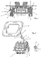
figure 1 est une vue en élévation latérale et en coupe représentant le montage des griffes conformes à l'invention, suivant deux demi-vues, la demi-vue de droite représentant la griffe en position escamotée et la demi-vue de gauche représentant la griffe en position déployée de service ; - la
figure 2 est une vue éclatée en perspective d'un appareillage muni des griffes conformes à l'invention ; - la
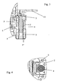
figure 3 est une vue partielle, en coupe, à plus grande échelle, représentant la griffe escamotée selon la demi-vue de droite de lafigure 1 , et - la
figure 4 est une vue partielle en plan correspondant à lafigure 3 .
- the
figure 1 is a side elevation and sectional view showing the mounting of the claws according to the invention, in two half-views, the right half-view showing the claw in the retracted position and the half-view of the left representing the claw in position deployed service; - the
figure 2 is an exploded perspective view of an apparatus provided with the claws according to the invention; - the
figure 3 is a partial view, in section, on a larger scale, showing the claw retracted according to the half-view of the right of thefigure 1 , and - the
figure 4 is a partial plan view corresponding to thefigure 3 .
Les
Les griffes 2 présentent une forme générale en U ou en étrier, dont les deux ailes verticales parallèles se terminent par des dents 2' et dont l'âme est pourvue d'un perçage 2" de passage d'une vis de serrage 4. Cette vis de serrage 4 est serrée dans le corps de l'appareillage électrique 1 pour réaliser le déplacement de la griffe 2 en direction de son support 1' du corps 1 en vue du déploiement des ailes la constituant et de l'accrochage des dents 2' dans la paroi de la boîte d'encastrement.The
Conformément à l'invention, chaque support 1' du corps 1 de l'appareillage est muni, de part et d'autre du bloc de butée 5, de rainures verticales 6 de réception des ailes verticales du U formant la griffe 2, ainsi que des dents 2' prévues aux extrémités desdites ailes, la profondeur de ces rainures 6 étant légèrement supérieure à l'épaisseur desdites ailes avec les dents 2'.According to the invention, each support 1 'of the
Ainsi, un escamotage total des griffes 2 et en particulier de leurs dents 2' est favorisé et une détérioration de l'isolation de câbles se trouvant dans le boîtier d'encastrement est évitée. Il en résulte qu'en position de repos des griffes 2, leurs ailes et, en particulier, leurs dents 2' sont entièrement escamotées dans les rainures 6, de sorte qu'il n'existe aucune aspérité sur le corps de l'appareillage 1 et qu'ainsi une possibilité de contact électrique entre lesdites griffes 2 et un éventuel conducteur est totalement exclu. Il s'ensuit que la sécurité des opérateurs contre des égratignures est également assurée.Thus, a total retraction of the
Afin de favoriser le basculement de la griffe 2, l'âme reliant les ailes verticales du U ou étrier la formant s'étend de manière inclinée par rapport à l'axe longitudinal desdites ailes.In order to promote the tilting of the
Selon une autre caractéristique de l'invention, le bloc de butée taraudé 5, dans lequel est vissée la vis 4 de serrage de la griffe 2, est sous forme d'un élément inséré dans le support l'et dépasse hors du support l' pour former un palier métallique rigide d'appui et de basculement pour la griffe 2, qui est isolée électriquement par rapport au support d'appareillage 11. En effet, comme il ressort plus particulièrement des
Le bloc de butée 5, plus particulièrement visible sur la
Chaque griffe 2 s'appuie contre un dispositif de rappel 3, inséré dans le support 1' en arrière de l'axe du bloc de butée 5 et de la vis de serrage 4 et formé par une lame de ressort estampée et pliée présentant une extrémité d'appui constituée par deux ailes parallèles s'étendant de part et d'autre de cet axe et s'appuyant contre l'âme du U formant la griffe 2, dans le prolongement des ailes verticales de ce U. Ainsi, du fait du montage de la griffe 2 sur la vis 4, l'appui des extrémités de l'âme du U formant la griffe 2 contre les ailes de la lame de ressort formant le dispositif de rappel 3, ledit dispositif de rappel 3 a tendance à appliquer l'âme du U formant la griffe 2 contre la tige filetée de la vis 4 et ainsi à faire basculer ladite griffe 2 dans une direction selon laquelle les ailes verticales du U la formant, et donc les dents 2', sont pivotées en direction du corps de l'appareillage 1, en position escamotée des griffes 2.Each
Le montage des griffes 2 conforme à l'invention est particulièrement simple à effectuer et rapide, chaque griffe 2 pouvant être insérée latéralement sur le support l' de manière à amener leur âme au-dessus du bloc de butée 5, le perçage 2" de ladite âme étant amené au-dessus du taraudage de ce dernier, puis la vis de serrage 4 étant mise en place. Par serrage de la vis 4, la griffe 2 est poussée en direction du bloc de butée 5 jusqu'à venir en appui par son âme inclinée contre l'arête extérieure dudit bloc de butée 5.The mounting of the
Pendant la poursuite du serrage de la vis 4, l'âme effectue alors un pivotement autour de l'arête extérieure du bloc de butée 5 et ses ailes munies des dents 2' sortent des rainures verticales 6 des supports l' jusqu'à entrer en contact avec la paroi intérieure d'un boîtier d'encastrement ou analogue, un serrage complémentaire de la vis 5 assurant un accrochage des dents 2' dans ladite paroi.During further tightening of the
Le logement des ailes de la griffe 2 munies des dents 2' dans les rainures verticales 6 des supports l', de part et d'autre du bloc de butée 5 permet d'assurer une isolation électrique supplémentaire desdites griffes 2, lors de la fixation de l'appareillage 1 et de la mise sous pression de ces griffes par les vis 4.The housing of the wings of the
Du fait d'un contact métal-métal entre chaque griffe 2 et le bloc de butée 5 correspondant et du serrage de la vis 4 dans ledit bloc de butée 5, il est possible d'exercer une force de serrage des griffes 2 plus importantes que celles qui pouvaient être exercées jusqu'à ce jour avec le montage des griffes existant. En effet, le bloc de butée 5 étant métallique, l'appui de la griffe 2 sur l'arête de ce bloc 5 s'effectue sans déformation possible dudit bloc, de sorte que la force exercée par la vis de serrage 4 est entièrement transmise à la griffe 2 et transformée en un mouvement de pivotement.Due to a metal-metal contact between each
En outre, la constitution même du bloc de butée 5 qui est inséré dans le support 1' du corps de l'appareillage 1, permet l'obtention d'un support 1' particulièrement rigide et ne risquant pas de se déformer en cas d'exercice d'une forte pression sur la vis de serrage 4, par exemple lors de la mise en place de l'appareillage, de sorte qu'une destruction dudit appareillage est évitée.In addition, the very constitution of the
Enfin, le dispositif de rappel sous forme d'un ressort à lame pliée inséré dans le support 1' derrière l'axe du bloc de butée 5 et de la vis de serrage 4 permet d'assurer une force de rappel constante de la griffe 2 en position de repos, tout en permettant un montage aisé de ladite griffe 2. Il est rappelé à cet effet que dans les modes de réalisation des griffes connues à ce jour, les dispositifs de rappel en position de repos présentent généralement d'importantes difficultés de montage.Finally, the return device in the form of a folded leaf spring inserted in the support 1 'behind the axis of the
Selon une forme de réalisation avantageuse de l'invention, il est possible de réaliser des griffes pour appareillages électriques, domestiques encastrés à monter dans des boîtes d'encastrement permettant d'assurer une parfaite isolation électrique de ces dernières par rapport au support d'appareillage.According to an advantageous embodiment of the invention, it is possible to make claws for electrical equipment, domestic recessed to mount in recessed boxes to ensure perfect electrical insulation of the latter relative to the equipment support .
Par ailleurs, le montage de griffe conforme à invention permet une manoeuvre et un guidage précis des griffes, tout en assurant une excellente tenue mécanique, même pour une utilisation en condition de montage sévère.Furthermore, the claw assembly according to the invention allows precise maneuvering and guiding of the claws, while ensuring excellent mechanical strength, even for use in severe assembly conditions.
Claims (5)
- A domestic, electrical, semi-embedded apparatus (1) such as a power outlet, a switch, an infrared detector etc., furnished with claws (2) for fastening in a flush-mounting box
the claws (2) being mounted on corresponding supports (1') of the apparatus which form an integral part of the body of the apparatus
the claws (2) being generally U-shaped or yoke-shaped, the two parallel, vertical flanges of which terminate in teeth (2') and the web of which is provided with a piercing (2') for the passage of a clamping screw (4), the clamping screws (4) being clamped in the body of the apparatus (1), screwed into tappings provided in the supports (1') or in metal inserts fitted into the latter
each support (1') of the body (1) of the apparatus being furnished with grooves (6) for receiving the vertical flanges of the U forming the claw (2), and the teeth (2') provided at the ends of said flanges, the depth of these grooves (6) being slightly greater than the depth of the said flanges with the teeth (2'),
the flanges of the claws (2), and, in particular, their teeth (2'), being, in the rest position of the claws (2), fully recessed into the grooves (6) so that there is no roughness on the body of the apparatus (1), the flanges furnished with the teeth (2') pivoting following the clamping of the clamping screw (4) in order to come out of the grooves (6) of the supports (1') as far as to come into contact with the inner wall of a flush-mounting box or similar element. - Apparatus according to Claim 1, characterized in that the web connecting the vertical flanges of the U or yoke forming each claw (2) extends in an inclined manner relative to the longitudinal axis of the said flanges, in order to promote the tilting of the claw (2).
- Apparatus according to Claim 1, characterized in that the support (1') comprises a tapped abutment block (5) into which the screw (4) for clamping the claw (2) is screwed, is in the form of an element inserted into the support (1') and protrudes from the support (1') in order to form a rigid metal bearing of support and of tilting for the claw (2), which is electrically insulated relative to the apparatus support (11).
- Apparatus according to Claim 3, characterized in that each abutment block (5) consists of a tapped hollow central barrel provided at its top portion with an element (5') extending transversely to the barrel (5) and having a quadrangular section, and fixed in the support (1') of the body of the apparatus (1) by means of a crimping (5"), the element (5') of the upper portion being inserted into a corresponding housing of the upper portion of the support (1') of the body of the apparatus (1) and protruding from this housing by at least one ridge turned towards the outside of the body of the apparatus (1) and forming a bearing of support and of tilting for the claw (2).
- Apparatus according to either one of Claims 3 and 4, characterized in that the claws (2) each rest against a return device (3), inserted into the support (1') behind the axle of the abutment block (5) and of the clamping screw (4) and formed by a stamped and folded spring blade having a bearing end consisting of two parallel flanges extending on either side of this axle and pressing against the web of the U forming the claw (2), in line with the vertical flanges of this U.
Priority Applications (3)
| Application Number | Priority Date | Filing Date | Title |
|---|---|---|---|
| EP10007671.0A EP2242158B1 (en) | 2007-01-23 | 2007-01-23 | Fastening claws for electrical appliances |
| PL10007671T PL2242158T3 (en) | 2007-01-23 | 2007-01-23 | Fastening claws for electrical appliances |
| DE10007671T DE10007671T1 (en) | 2007-01-23 | 2007-01-23 | Mounting hook for electrical appliances |
Applications Claiming Priority (2)
| Application Number | Priority Date | Filing Date | Title |
|---|---|---|---|
| EP10007671.0A EP2242158B1 (en) | 2007-01-23 | 2007-01-23 | Fastening claws for electrical appliances |
| EP07360003A EP1950858B1 (en) | 2007-01-23 | 2007-01-23 | Fastening elements for installation devices by using claws |
Related Parent Applications (1)
| Application Number | Title | Priority Date | Filing Date |
|---|---|---|---|
| EP07360003.3 Division | 2007-01-23 |
Publications (3)
| Publication Number | Publication Date |
|---|---|
| EP2242158A2 EP2242158A2 (en) | 2010-10-20 |
| EP2242158A3 EP2242158A3 (en) | 2011-10-19 |
| EP2242158B1 true EP2242158B1 (en) | 2013-06-12 |
Family
ID=38123839
Family Applications (2)
| Application Number | Title | Priority Date | Filing Date |
|---|---|---|---|
| EP10007671.0A Revoked EP2242158B1 (en) | 2007-01-23 | 2007-01-23 | Fastening claws for electrical appliances |
| EP07360003A Active EP1950858B1 (en) | 2007-01-23 | 2007-01-23 | Fastening elements for installation devices by using claws |
Family Applications After (1)
| Application Number | Title | Priority Date | Filing Date |
|---|---|---|---|
| EP07360003A Active EP1950858B1 (en) | 2007-01-23 | 2007-01-23 | Fastening elements for installation devices by using claws |
Country Status (7)
| Country | Link |
|---|---|
| EP (2) | EP2242158B1 (en) |
| AT (1) | ATE532245T1 (en) |
| DE (2) | DE10007671T1 (en) |
| DK (1) | DK1950858T3 (en) |
| ES (2) | ES2426775T3 (en) |
| PL (2) | PL1950858T3 (en) |
| PT (2) | PT1950858E (en) |
Families Citing this family (2)
| Publication number | Priority date | Publication date | Assignee | Title |
|---|---|---|---|---|
| ES2426775T3 (en) | 2007-01-23 | 2013-10-25 | Hager Electro S.A.S. | Fixing claws for electrical equipment |
| EP3859919A1 (en) | 2020-01-30 | 2021-08-04 | Berker GmbH & Co. KG | Electrical device |
Family Cites Families (7)
| Publication number | Priority date | Publication date | Assignee | Title |
|---|---|---|---|---|
| DE3823117C2 (en) | 1988-07-08 | 1994-04-14 | Asea Brown Boveri | Electrical installation device |
| DE4125767C1 (en) | 1991-08-03 | 1992-12-10 | Gira Giersiepen Gmbh & Co Kg, 5608 Radevormwald, De | Electrical installation appts. e.g. socket, switch, pushbutton - has twin-shank claws on opposite sides of socket in carrying ring allowing flush fitting |
| FR2763179B1 (en) * | 1997-05-07 | 1999-08-20 | Alombard Sa | CLAW FIXING DEVICE FOR SUPPORT |
| FR2770937B1 (en) * | 1997-11-10 | 2000-01-28 | Legrand Sa | BUILT-IN ELECTRICAL APPLIANCE WITH CLAW FIXING |
| DE29918584U1 (en) * | 1999-10-21 | 2000-03-16 | Manfred Roethel Elektrotechnik | Assembly with translationally movable screw |
| FR2844106B1 (en) * | 2002-08-28 | 2004-11-19 | Legrand Sa | DOMESTIC ELECTRICAL INSTALLATION APPARATUS INCLUDING PROTECTION AGAINST SPRAY OF LIQUID |
| ES2426775T3 (en) | 2007-01-23 | 2013-10-25 | Hager Electro S.A.S. | Fixing claws for electrical equipment |
-
2007
- 2007-01-23 ES ES10007671T patent/ES2426775T3/en active Active
- 2007-01-23 AT AT07360003T patent/ATE532245T1/en active
- 2007-01-23 PT PT07360003T patent/PT1950858E/en unknown
- 2007-01-23 PL PL07360003T patent/PL1950858T3/en unknown
- 2007-01-23 DK DK07360003.3T patent/DK1950858T3/en active
- 2007-01-23 EP EP10007671.0A patent/EP2242158B1/en not_active Revoked
- 2007-01-23 PT PT100076710T patent/PT2242158E/en unknown
- 2007-01-23 DE DE10007671T patent/DE10007671T1/en active Pending
- 2007-01-23 ES ES07360003T patent/ES2376906T3/en active Active
- 2007-01-23 EP EP07360003A patent/EP1950858B1/en active Active
- 2007-01-23 PL PL10007671T patent/PL2242158T3/en unknown
- 2007-01-23 DE DE202007019154U patent/DE202007019154U1/en not_active Expired - Lifetime
Also Published As
| Publication number | Publication date |
|---|---|
| ES2376906T3 (en) | 2012-03-20 |
| DE202007019154U1 (en) | 2010-11-18 |
| EP1950858A1 (en) | 2008-07-30 |
| PL1950858T3 (en) | 2012-11-30 |
| EP2242158A2 (en) | 2010-10-20 |
| DK1950858T3 (en) | 2012-02-27 |
| ATE532245T1 (en) | 2011-11-15 |
| PL2242158T3 (en) | 2013-11-29 |
| PT1950858E (en) | 2012-02-07 |
| PT2242158E (en) | 2013-09-05 |
| ES2426775T3 (en) | 2013-10-25 |
| EP1950858B1 (en) | 2011-11-02 |
| DE10007671T1 (en) | 2013-06-13 |
| EP2242158A3 (en) | 2011-10-19 |
Similar Documents
| Publication | Publication Date | Title |
|---|---|---|
| FR2694138A1 (en) | Adaptation system between an antenna plug and a base of a radiotelephone. | |
| EP2541684A1 (en) | Connector for mutually connecting two electrical cables | |
| WO1997028578A1 (en) | Branching connector for an underground cable | |
| FR2789511A1 (en) | INSTALLATION COMPRISING AN ELECTRICAL SWITCHING APPARATUS AND A CABLE INTERLOCK | |
| EP2242158B1 (en) | Fastening claws for electrical appliances | |
| FR2901415A1 (en) | Four pole connector for underground power distribution grid, has plug with return provided with sharp teeth at its free end to perforate outer cover, where teeth is projected relative to contact surface of neutral connector | |
| EP1531519B1 (en) | Electrical terminal and electrical protection apparatus containing such a terminal | |
| EP0909473B1 (en) | Sleeve and mobile connection for electric supply | |
| EP1568109B1 (en) | Electrical contact with elastic return and electrical connection element equipped with at least one such contact | |
| EP0592336B1 (en) | Connecting terminal for electric power equipment | |
| EP2518831B1 (en) | Connecting sleeve for electrical cables | |
| FR2963488A1 (en) | Multipolar electric connection nozzle for connecting e.g. electric copper wire of electrical cable on electric terminal of electric meter in electrical box, has housing whose electrical contact member is connected electrically to wire | |
| EP3358679A1 (en) | Device for connecting a conductor | |
| EP1531525B1 (en) | Cable clamp with enlarged clamping surface and terminal block comprising it | |
| FR2842655A1 (en) | Electrical energy distribution cable shunt connector having jaw grip sections formed isolating material and having anchorage extension with central bolt/nut holed and end bolt ring pretensioner. | |
| EP1538718B1 (en) | Mounting claws return mechanism | |
| FR2527015A1 (en) | Demountable cylindrical connector for single-core cable - has male and female sections which join in snap-action push-fit which can be disconnected without special tool | |
| FR2585192A1 (en) | Electrical connector intended for producing an electrical branch-off from a power cable formed from a conductor surrounded by an insulating jacket | |
| EP3246992B1 (en) | Connection device for a terminal section of an electric cable | |
| EP2366189B1 (en) | Busbar bushing with an orientationally adjustable protective casing dedicated to the connector | |
| FR2901413A1 (en) | Derivation cable connector for use with electric energy transport cable, has threaded pin and screw provided distinctively from another threaded pin and another screw that control adaptation of relative position of shells | |
| FR2709883A1 (en) | Electric contact with elastic return. | |
| EP2677602A1 (en) | Coupling connector for at least two electrical cables | |
| FR2597664A1 (en) | Electrical connection device of the insulation-displacement type | |
| FR2998723A1 (en) | Anchoring system for insulated electric cable for transport and distribution of electric energy, has connector including conductive contact element movable in translation along portion of anchor loop while electrically connected to loop |
Legal Events
| Date | Code | Title | Description |
|---|---|---|---|
| PUAI | Public reference made under article 153(3) epc to a published international application that has entered the european phase |
Free format text: ORIGINAL CODE: 0009012 |
|
| AC | Divisional application: reference to earlier application |
Ref document number: 1950858 Country of ref document: EP Kind code of ref document: P |
|
| AK | Designated contracting states |
Kind code of ref document: A2 Designated state(s): AT BE BG CH CY CZ DE DK EE ES FI FR GB GR HU IE IS IT LI LT LU LV MC NL PL PT RO SE SI SK TR |
|
| PUAL | Search report despatched |
Free format text: ORIGINAL CODE: 0009013 |
|
| AK | Designated contracting states |
Kind code of ref document: A3 Designated state(s): AT BE BG CH CY CZ DE DK EE ES FI FR GB GR HU IE IS IT LI LT LU LV MC NL PL PT RO SE SI SK TR |
|
| AX | Request for extension of the european patent |
Extension state: AL BA HR MK RS |
|
| RIC1 | Information provided on ipc code assigned before grant |
Ipc: H02G 3/18 20060101AFI20110914BHEP |
|
| 17P | Request for examination filed |
Effective date: 20120109 |
|
| RAP1 | Party data changed (applicant data changed or rights of an application transferred) |
Owner name: BERKER GMBH & CO. KG |
|
| RAP1 | Party data changed (applicant data changed or rights of an application transferred) |
Owner name: HAGER ELECTRO S.A.S. |
|
| 17Q | First examination report despatched |
Effective date: 20120410 |
|
| TPAC | Observations filed by third parties |
Free format text: ORIGINAL CODE: EPIDOSNTIPA |
|
| TPAC | Observations filed by third parties |
Free format text: ORIGINAL CODE: EPIDOSNTIPA |
|
| GRAP | Despatch of communication of intention to grant a patent |
Free format text: ORIGINAL CODE: EPIDOSNIGR1 |
|
| REG | Reference to a national code |
Ref country code: DE Ref legal event code: R082 Representative=s name: BITTERICH, DR. KELLER, SCHWERTFEGER, DE Ref country code: DE Ref legal event code: R082 Ref document number: 602007031070 Country of ref document: DE Representative=s name: DR. KELLER, SCHWERTFEGER, DE Ref country code: DE Ref legal event code: R082 Ref document number: 602007031070 Country of ref document: DE Representative=s name: PATENTANWAELTE DR. KELLER, SCHWERTFEGER, DE |
|
| GRAS | Grant fee paid |
Free format text: ORIGINAL CODE: EPIDOSNIGR3 |
|
| GRAA | (expected) grant |
Free format text: ORIGINAL CODE: 0009210 |
|
| INTG | Intention to grant announced |
Effective date: 20130416 |
|
| AC | Divisional application: reference to earlier application |
Ref document number: 1950858 Country of ref document: EP Kind code of ref document: P |
|
| AK | Designated contracting states |
Kind code of ref document: B1 Designated state(s): AT BE BG CH CY CZ DE DK EE ES FI FR GB GR HU IE IS IT LI LT LU LV MC NL PL PT RO SE SI SK TR |
|
| REG | Reference to a national code |
Ref country code: GB Ref legal event code: FG4D Free format text: NOT ENGLISH |
|
| REG | Reference to a national code |
Ref country code: DE Ref legal event code: R210 Ref document number: 602007031070 Country of ref document: DE Effective date: 20130613 |
|
| REG | Reference to a national code |
Ref country code: CH Ref legal event code: EP |
|
| REG | Reference to a national code |
Ref country code: AT Ref legal event code: REF Ref document number: 616991 Country of ref document: AT Kind code of ref document: T Effective date: 20130615 |
|
| REG | Reference to a national code |
Ref country code: IE Ref legal event code: FG4D Free format text: LANGUAGE OF EP DOCUMENT: FRENCH |
|
| REG | Reference to a national code |
Ref country code: DE Ref legal event code: R096 Ref document number: 602007031070 Country of ref document: DE Effective date: 20130814 |
|
| REG | Reference to a national code |
Ref country code: DE Ref legal event code: R082 Ref document number: 602007031070 Country of ref document: DE Representative=s name: DR. KELLER, SCHWERTFEGER, DE Ref country code: DE Ref legal event code: R082 Ref document number: 602007031070 Country of ref document: DE Representative=s name: PATENTANWAELTE DR. KELLER, SCHWERTFEGER, DE |
|
| REG | Reference to a national code |
Ref country code: PT Ref legal event code: SC4A Free format text: AVAILABILITY OF NATIONAL TRANSLATION Effective date: 20130829 |
|
| REG | Reference to a national code |
Ref country code: ES Ref legal event code: FG2A Ref document number: 2426775 Country of ref document: ES Kind code of ref document: T3 Effective date: 20131025 |
|
| PG25 | Lapsed in a contracting state [announced via postgrant information from national office to epo] |
Ref country code: GR Free format text: LAPSE BECAUSE OF FAILURE TO SUBMIT A TRANSLATION OF THE DESCRIPTION OR TO PAY THE FEE WITHIN THE PRESCRIBED TIME-LIMIT Effective date: 20130913 Ref country code: FI Free format text: LAPSE BECAUSE OF FAILURE TO SUBMIT A TRANSLATION OF THE DESCRIPTION OR TO PAY THE FEE WITHIN THE PRESCRIBED TIME-LIMIT Effective date: 20130612 Ref country code: SE Free format text: LAPSE BECAUSE OF FAILURE TO SUBMIT A TRANSLATION OF THE DESCRIPTION OR TO PAY THE FEE WITHIN THE PRESCRIBED TIME-LIMIT Effective date: 20130612 Ref country code: SI Free format text: LAPSE BECAUSE OF FAILURE TO SUBMIT A TRANSLATION OF THE DESCRIPTION OR TO PAY THE FEE WITHIN THE PRESCRIBED TIME-LIMIT Effective date: 20130612 Ref country code: LT Free format text: LAPSE BECAUSE OF FAILURE TO SUBMIT A TRANSLATION OF THE DESCRIPTION OR TO PAY THE FEE WITHIN THE PRESCRIBED TIME-LIMIT Effective date: 20130612 |
|
| REG | Reference to a national code |
Ref country code: NL Ref legal event code: VDEP Effective date: 20130612 |
|
| REG | Reference to a national code |
Ref country code: LT Ref legal event code: MG4D |
|
| PG25 | Lapsed in a contracting state [announced via postgrant information from national office to epo] |
Ref country code: BG Free format text: LAPSE BECAUSE OF FAILURE TO SUBMIT A TRANSLATION OF THE DESCRIPTION OR TO PAY THE FEE WITHIN THE PRESCRIBED TIME-LIMIT Effective date: 20130912 |
|
| REG | Reference to a national code |
Ref country code: PL Ref legal event code: T3 |
|
| PG25 | Lapsed in a contracting state [announced via postgrant information from national office to epo] |
Ref country code: LV Free format text: LAPSE BECAUSE OF FAILURE TO SUBMIT A TRANSLATION OF THE DESCRIPTION OR TO PAY THE FEE WITHIN THE PRESCRIBED TIME-LIMIT Effective date: 20130612 |
|
| PG25 | Lapsed in a contracting state [announced via postgrant information from national office to epo] |
Ref country code: SK Free format text: LAPSE BECAUSE OF FAILURE TO SUBMIT A TRANSLATION OF THE DESCRIPTION OR TO PAY THE FEE WITHIN THE PRESCRIBED TIME-LIMIT Effective date: 20130612 Ref country code: IS Free format text: LAPSE BECAUSE OF FAILURE TO SUBMIT A TRANSLATION OF THE DESCRIPTION OR TO PAY THE FEE WITHIN THE PRESCRIBED TIME-LIMIT Effective date: 20131012 Ref country code: EE Free format text: LAPSE BECAUSE OF FAILURE TO SUBMIT A TRANSLATION OF THE DESCRIPTION OR TO PAY THE FEE WITHIN THE PRESCRIBED TIME-LIMIT Effective date: 20130612 Ref country code: CZ Free format text: LAPSE BECAUSE OF FAILURE TO SUBMIT A TRANSLATION OF THE DESCRIPTION OR TO PAY THE FEE WITHIN THE PRESCRIBED TIME-LIMIT Effective date: 20130612 |
|
| PG25 | Lapsed in a contracting state [announced via postgrant information from national office to epo] |
Ref country code: NL Free format text: LAPSE BECAUSE OF FAILURE TO SUBMIT A TRANSLATION OF THE DESCRIPTION OR TO PAY THE FEE WITHIN THE PRESCRIBED TIME-LIMIT Effective date: 20130612 Ref country code: RO Free format text: LAPSE BECAUSE OF FAILURE TO SUBMIT A TRANSLATION OF THE DESCRIPTION OR TO PAY THE FEE WITHIN THE PRESCRIBED TIME-LIMIT Effective date: 20130612 |
|
| PLBI | Opposition filed |
Free format text: ORIGINAL CODE: 0009260 |
|
| 26 | Opposition filed |
Opponent name: MERTEN GMBH & CO. KG Effective date: 20140311 |
|
| PLAX | Notice of opposition and request to file observation + time limit sent |
Free format text: ORIGINAL CODE: EPIDOSNOBS2 |
|
| PG25 | Lapsed in a contracting state [announced via postgrant information from national office to epo] |
Ref country code: DK Free format text: LAPSE BECAUSE OF FAILURE TO SUBMIT A TRANSLATION OF THE DESCRIPTION OR TO PAY THE FEE WITHIN THE PRESCRIBED TIME-LIMIT Effective date: 20130612 |
|
| REG | Reference to a national code |
Ref country code: DE Ref legal event code: R026 Ref document number: 602007031070 Country of ref document: DE Effective date: 20140311 |
|
| PG25 | Lapsed in a contracting state [announced via postgrant information from national office to epo] |
Ref country code: IT Free format text: LAPSE BECAUSE OF FAILURE TO SUBMIT A TRANSLATION OF THE DESCRIPTION OR TO PAY THE FEE WITHIN THE PRESCRIBED TIME-LIMIT Effective date: 20130612 |
|
| PLAF | Information modified related to communication of a notice of opposition and request to file observations + time limit |
Free format text: ORIGINAL CODE: EPIDOSCOBS2 |
|
| BERE | Be: lapsed |
Owner name: HAGER ELECTRO S.A.S. Effective date: 20140131 |
|
| PG25 | Lapsed in a contracting state [announced via postgrant information from national office to epo] |
Ref country code: MC Free format text: LAPSE BECAUSE OF FAILURE TO SUBMIT A TRANSLATION OF THE DESCRIPTION OR TO PAY THE FEE WITHIN THE PRESCRIBED TIME-LIMIT Effective date: 20130612 Ref country code: LU Free format text: LAPSE BECAUSE OF FAILURE TO SUBMIT A TRANSLATION OF THE DESCRIPTION OR TO PAY THE FEE WITHIN THE PRESCRIBED TIME-LIMIT Effective date: 20140123 |
|
| REG | Reference to a national code |
Ref country code: CH Ref legal event code: PL |
|
| GBPC | Gb: european patent ceased through non-payment of renewal fee |
Effective date: 20140123 |
|
| PLBB | Reply of patent proprietor to notice(s) of opposition received |
Free format text: ORIGINAL CODE: EPIDOSNOBS3 |
|
| PG25 | Lapsed in a contracting state [announced via postgrant information from national office to epo] |
Ref country code: LI Free format text: LAPSE BECAUSE OF NON-PAYMENT OF DUE FEES Effective date: 20140131 Ref country code: CH Free format text: LAPSE BECAUSE OF NON-PAYMENT OF DUE FEES Effective date: 20140131 |
|
| REG | Reference to a national code |
Ref country code: IE Ref legal event code: MM4A |
|
| PG25 | Lapsed in a contracting state [announced via postgrant information from national office to epo] |
Ref country code: GB Free format text: LAPSE BECAUSE OF NON-PAYMENT OF DUE FEES Effective date: 20140123 |
|
| REG | Reference to a national code |
Ref country code: FR Ref legal event code: PLFP Year of fee payment: 9 |
|
| PG25 | Lapsed in a contracting state [announced via postgrant information from national office to epo] |
Ref country code: IE Free format text: LAPSE BECAUSE OF NON-PAYMENT OF DUE FEES Effective date: 20140123 Ref country code: BE Free format text: LAPSE BECAUSE OF NON-PAYMENT OF DUE FEES Effective date: 20140131 |
|
| PGFP | Annual fee paid to national office [announced via postgrant information from national office to epo] |
Ref country code: PT Payment date: 20150109 Year of fee payment: 9 Ref country code: DE Payment date: 20150129 Year of fee payment: 9 Ref country code: ES Payment date: 20150116 Year of fee payment: 9 |
|
| PGFP | Annual fee paid to national office [announced via postgrant information from national office to epo] |
Ref country code: TR Payment date: 20150109 Year of fee payment: 9 Ref country code: FR Payment date: 20150115 Year of fee payment: 9 Ref country code: AT Payment date: 20150115 Year of fee payment: 9 Ref country code: PL Payment date: 20150112 Year of fee payment: 9 |
|
| REG | Reference to a national code |
Ref country code: DE Ref legal event code: R064 Ref document number: 602007031070 Country of ref document: DE Ref country code: DE Ref legal event code: R103 Ref document number: 602007031070 Country of ref document: DE |
|
| RDAF | Communication despatched that patent is revoked |
Free format text: ORIGINAL CODE: EPIDOSNREV1 |
|
| RDAG | Patent revoked |
Free format text: ORIGINAL CODE: 0009271 |
|
| STAA | Information on the status of an ep patent application or granted ep patent |
Free format text: STATUS: PATENT REVOKED |
|
| REG | Reference to a national code |
Ref country code: PT Ref legal event code: MP4A Effective date: 20151130 |
|
| 27W | Patent revoked |
Effective date: 20150623 |
|
| REG | Reference to a national code |
Ref country code: AT Ref legal event code: MA03 Ref document number: 616991 Country of ref document: AT Kind code of ref document: T Effective date: 20150623 |
|
| PG25 | Lapsed in a contracting state [announced via postgrant information from national office to epo] |
Ref country code: CY Free format text: LAPSE BECAUSE OF FAILURE TO SUBMIT A TRANSLATION OF THE DESCRIPTION OR TO PAY THE FEE WITHIN THE PRESCRIBED TIME-LIMIT Effective date: 20130612 |