EP2242081A1 - Safety load connecting block - Google Patents
Safety load connecting block Download PDFInfo
- Publication number
- EP2242081A1 EP2242081A1 EP10160161A EP10160161A EP2242081A1 EP 2242081 A1 EP2242081 A1 EP 2242081A1 EP 10160161 A EP10160161 A EP 10160161A EP 10160161 A EP10160161 A EP 10160161A EP 2242081 A1 EP2242081 A1 EP 2242081A1
- Authority
- EP
- European Patent Office
- Prior art keywords
- housing part
- fastening means
- face
- fastening
- lateral surface
- Prior art date
- Legal status (The legal status is an assumption and is not a legal conclusion. Google has not performed a legal analysis and makes no representation as to the accuracy of the status listed.)
- Granted
Links
Images
Classifications
-
- H—ELECTRICITY
- H01—ELECTRIC ELEMENTS
- H01H—ELECTRIC SWITCHES; RELAYS; SELECTORS; EMERGENCY PROTECTIVE DEVICES
- H01H85/00—Protective devices in which the current flows through a part of fusible material and this current is interrupted by displacement of the fusible material when this current becomes excessive
- H01H85/02—Details
- H01H85/0208—Tools for inserting and removing fuses
Definitions
- the present invention relates to fuse switch disconnectors having a housing lower part, in which at least one electrical busbar connection, which is connected to a first securing receptacle, and an outgoing connection, which is connected to a second securing receptacle, is arranged, a housing upper part, a switch cover arranged pivotably relative to the housing upper part, the at least one holding device for a fuse link, and at least one attachment means for releasably securing the housing top to the housing base, said attachment means having an elongated body having a lateral surface, a front side and a mounting portion, wherein the mounting portion in a first, the housing lower part with the upper housing part locking position and in a second, the lower housing part and the upper housing part releasing position is movable.
- Fuse-breaker strips mostly low-voltage, high-performance (NH) fused-switch disconnectors, have long been known and serve to provide fused electrical outlets from busbars that can be disconnected under load.
- the devices generally include one or more fuse bases disposed within the housing.
- Corresponding fuse links are mounted on one or more switch covers, so that with a closed switch cover the fuse links are inserted into the fuse bases and make a connection between the respective - connectable to the busbars - feed contacts and the outgoing contacts. When opening the switch cover, the fuse links are pulled out of the fuse bases so that the connection is broken.
- the housing bases When mounting such fuse switch disconnectors in cabinets, the housing bases are first attached by means of angled out of the housing lower parts busbar connections to the busbars and then screwed with them. Subsequently, in the known from the prior art Sich ceremoniesslastschleisten an upper housing part attached to the lower housing part, the open or the switch cover and the upper housing part by means of one or more fastening means which are mounted in the upper housing part and arranged in the upper housing part itself, firmly connected to the lower housing part ,
- the fastening means are pivoted by means of a screwdriver from an unlocked to a locked position.
- the locking mechanisms known from the prior art are designed such that the fastening means are arranged inside the housing upper part, in most cases even under the securing inserts. That is, for removing the upper housing part, for example, when converting an electrical system, the housing must first be opened before the upper housing part can be removed.
- an attachment of the upper housing part to the lower housing part is to be made possible with closed shift lids, without even unlocking the upper housing part and lower housing part would be possible with closed shift lids.
- a fuse load switch bar in particular an NH fuse switch disconnector
- a housing lower part in which at least one electrical busbar connection, which is connected to a first fuse holder, and a outgoing terminal, which is connected to a second fuse holder, arranged is an upper housing part, a cover arranged opposite the upper housing pivotally mounted cover having at least one holding device for a fuse link, and at least one fastening means for releasably securing the upper housing part to the housing lower part
- the fastening means has a longitudinally extended body with a lateral surface, a front side and a Fastening portion, wherein the attachment portion in a first, the lower housing part with the upper housing part locking position and in a second, the housing lower part and the G the housing is releasable position movable
- the fastening means is configured such that by exerting a force on the front side or on a front side arranged element, the fixing portion is movable
- the busbar connection is typically led out of the lower housing part on the rear side.
- the busbar connection is hook-shaped, so that the fuse load switching strip can be suspended on a busbar.
- the busbar connection can be screwed or otherwise connectable to the busbar.
- the securing receptacles connected to the busbar connection or the outgoing connection form a fuse lower part in which a fuse link, which can be connected to the corresponding holding device of the switching cover, can be accommodated.
- the fuse load switching strip is three-pole switchable and has only a switch cover on which three fuse links are receivable. When opening the switch cover, all three fuse links are removed from the respective fuse bases and all three phases are switched free of load.
- the fuse load switch bar on three switch cover which can be opened and closed separately.
- Such a fuse load switching strip is single-pole switchable.
- the attachment portion of the fastener provides a lock between the housing bottom and the housing top. It can the attachment portion be executed, for example, a bayonet type, but also simpler designs are conceivable in which locking elements are performed when placing the upper housing part on the lower housing part by corresponding recesses in the lower housing part and then pivoted so that they engage behind corresponding holding portions of the housing lower part.
- the fastening portion of the fastening means on a projecting from the lateral surface locking element which undercuts a holding portion of the housing base or the housing top in the first position of the mounting portion, so that it locks the two housing parts together.
- the inventive design of the fastening means such that it can be moved by exerting a force on its end face or arranged on or in the end face element in a position in which the attachment portion is located in the first, the lower housing part and the upper housing part locking position in combination with a receptacle for a tool on the lateral surface of the fastener, makes it possible to design the fuse load switch bar so that the end face of the fastener are arranged accessible in particular from the outside, especially with closed switching lids.
- a force on the front side of the fastener may be a linear force or a torque.
- the fastening means is designed so that the fastening portion is movable by exerting force on the end face or an element arranged on this only in the first, locking position and not in the second, unlocked position.
- the fastening means can be locked only with the housing closed or closed switch cover, but not unlocked.
- the attachment means is therefore designed to be compressible in an axial direction, i. when exerting a substantially linear force on the front side of the elongated body, connects to the second housing part.
- the fastening means is pivotably mounted about an axis of rotation, wherein the fastening portion is guided on chamfers of the corresponding element of the housing part to be connected, that causes an axially acting on the end face of the fastening means force that this about the axis of rotation in an interlocking position the fastening portion is pivoted.
- the attachment means is pivotally mounted about a rotation axis, so that the attachment portion is pivotally movable in the first, the lower housing part with the upper housing part locking position, wherein on the front side a recess is arranged with two stop surfaces for the support surfaces of a screwdriver wherein the stop surfaces are arranged so that only in a first direction of rotation torque from the screwdriver is transferable to the fastener.
- Such an arrangement on the front side of the fastener makes it possible, by engaging a screwdriver with the recess and thus with the two separate stop surfaces, to rotate the fastener by means of the screwdriver in a first direction of rotation while not using the same fastener with the screwdriver can be pivoted in the opposite second direction of rotation.
- the fastener can be pivoted by means of the screwdriver only for locking, while a release of the fastener is impossible.
- the end face has at least one guide bevel, which is arranged such that, when a screwdriver is rotated, the screwdriver is led out of the depression in a second direction of rotation opposite to the first direction of rotation.
- the receptacle for a tool in the lateral surface of the fastening means may for example be a through hole of the fastening means, in which in a direction substantially perpendicular to a rotational axis of the fastening means a pin is inserted, by means of which a torque on the fastening means is exercisable.
- the lateral surface of the main body at least partially on two substantially mutually parallel surface sections for receiving a wrench.
- the lateral surface of the base body is at least partially formed by the side surfaces of a regular hexagon in the manner of a hexagon screw, so that the fastening means by means of a commercially available open-end wrench is pivotable about an axis of rotation.
- the receptacle for a tool is arranged on the lateral surface of the fastening means it is disposed within the housing when the mounting portion is in the first, locked position. Only by opening the housing, preferably by opening the switch cover, can ever bring an open-end wrench or other tool with the receptacle for a tool on the lateral surface of the body in engagement. When the switch cover is open, however, as required, the fuse load switch bar is load-free.
- a recess is provided in the housing upper part or in the switch cover, which is arranged substantially in extension of the axis of rotation of the fastening means and through which a screwdriver with the front side of the fastening means can be brought into engagement.
- a screwdriver can be easily by a, preferably circular, opening in the upper housing part or in the switch cover into the housing and introduce there with the front side of the fastener or an element disposed thereon, in particular one or more stop surfaces, engage.
- the fastening means is arranged and arranged such that its end side engages through a recess in the housing upper part or in the switching cover when the latter is in a position closing the housing upper part. In this way, the screwdriver does not have to be inserted into the housing, but can be brought on the outside of the housing with the fastener engaged.
- the front side of the fastening means closes substantially flush with the upper housing part or with the switching cover when it is arranged in a position closing the upper housing part. In this way, can effectively prevent the fastener is gripped, for example, with a pair of pliers or any other tool on its lateral surface and the mounting portion is pivoted from its first locking position to its second unlocked position.
- the lateral surface of the fastening means starting from the end face, has a substantially cylindrical section which, when the fastening section is in the first position, extends into the housing.
- a cylindrical section can not or poorly and then bring intentionally with a tool in engagement. Accidental unlocking of the fastener before opening the switch cover is prevented.
- the cylindrical portion has a height in a range of 2 mm to 50 mm, and preferably in a range of 5 mm to 10 mm.
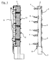
- FIG. 1 shows an upper housing part 1 and a lower housing part 2, which are connectable by means of a fastening means 10 to a fuse load switching strip according to the invention, in a schematic side view.
- the illustrated fuse load switching edge is an NH fuse-switch-disconnector for three phases. Therefore, the lower housing part on three busbar connections 3, which are each connectable to a busbar of a cabinet.
- the busbar connections 3 are hook-shaped, so that the lower housing part 2 can be suspended with the busbar connections 3 on the busbars and then screwed to these.
- the lower housing part is designed so that it can accommodate three fuse links.
- Each of the busbar terminals 3 is electrically connected to a first fuse receptacle 4, which can receive a fuse link by means of resiliently biased contacts electrically conductive.
- Each first fuse holder 4 is arranged opposite a second fuse holder 5, which receives the second contact of a fuse link in an electrically conductive manner.
- This second fuse holder 5 in turn is electrically connected to a outgoing terminal 6 of the fuse load switching strip.
- FIG. 1 Only a single visible because the others are arranged hidden in the side view in the outlet region 7 of the housing base 2.
- the upper housing part 1 can now be attached to the lower housing part 2, that the securing receptacles 4, 5 and the outgoing terminals 6 are completely covered by the upper housing part 1 and are accommodated in the housing 1, 2, 8.
- the shift cover 8 is hinged at its lower end relative to the upper housing part 1 and can be opened and closed by means of a shift lever 9.
- the fuse links to be received in the fuse bases formed from the fuse holders 4, 5 are connected to corresponding holding devices of the switch cover 8 so that opening of the switch lid 8 results in all fuse links being taken out of the fuse holders 4, 5 substantially simultaneously Current flow is interrupted by the busbar terminals 3 to the outgoing terminals 6.
- the arrangement shown is therefore three-pole switchable.
- FIG. 1 Clearly visible in FIG. 1 also two fastening bolts 10, whose lower ends or fastening sections 10 protrude beyond the housing part 1. These engage in the assembly of the upper housing part 1 and the lower housing part 2 in corresponding recesses of the lower housing part 2 and lock by pivoting about an axis of rotation of the housing lower part 2. As in FIG. 1 indicated in the drawing, the locked positions of the two fastening bolts 10 are rotated by 90 ° from each other.
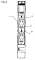
- FIG. 2 shows a plan view from above of the accommodated on the lower housing part 2 housing upper part 1, wherein the position of the fastening bolt 10 between the individual securing elements is clearly visible.
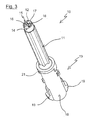
- FIG. 3 shows a three-dimensional lateral view of a locking bolt 10, as it in the housing upper part 1 from FIGS. 1 and 2 is rotatably mounted.
- the fastening bolt 10 has a substantially elongated base body with a lateral surface 11 and an end face or end face 12.
- a fastening portion 13 is arranged, which serves the locking or fastening of the housing lower part 2 on the upper housing part 1.
- the lateral surface 11 is essentially formed by the side surfaces of a regular hexagon, so that the lateral surface 11 as a whole forms a hexagon screw on which a commercial open-end wrench can begin.
- the lateral surface 14 is cylindrical, wherein the cylinder has a height of about 5 mm.
- the end face 12 has a recess 15 with two stop surfaces 16.
- a conventional screwdriver can be inserted into the recess 15 and engage with the stop surfaces 16.
- the stop surfaces 16 are arranged so that the screwdriver transmits by a clockwise rotation of the torque exerted on it on the stop surfaces 16 and thus on the pivotally mounted mounting bolts 10.
- two chamfers are further provided 17 which are arranged opposite the abutment surfaces 16, so that an inserted into the recess 15 screwdriver is led out with a counterclockwise rotation of the screwdriver from the recess 15 and a torque transmission from the screwdriver on the mounting bolt 10 in this direction is excluded.
- the attachment portion 13 has at its lower end on two of the lateral surface 18 of the mounting portion 13 projecting locking elements 19 which undercut a holding portion 20 of the housing base 2 in the locked position of the fastening bolt 10.
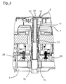
- FIG. 4 shows the fastening bolt 10 in the installed and locked state. While the fastening bolt 10 is mounted by means of the guide ring 21 pivotally mounted on the housing upper part 1, the holding portions 19 engage behind a corresponding projection 20 on the housing lower part 2. The end face 12 of the fastening bolt 10 engages through a hole 22 in the switch cover 22. If the mounting portion 13 is located of the fastening bolt 10 in the in FIG. 4 shown locked position and the switch cover 22 is closed, so the frontal surface 12 of the mounting bolt 10 is substantially flush with the cover 22 from. In the closed state of the housing 1, 2, 8, therefore, only the end face 12 or the depression 15 of the fastening bolt 10 arranged therein is accessible from the outside, but not the hexagonal jacket surface 11 for receiving a wrench.
- the switch cover 22 is not only hinged against the upper housing part 1, but can be removed completely from the upper housing part 1 together with the other two switching lids and the shift lever 9 for easier access to the interior of the housing 1, 2.
Abstract
Description
Die vorliegende Erfindung betrifft Sicherungslastschaltleisten mit einem Gehäuseunterteil, in dem mindestens ein elektrischer Sammelschienenanschluss, der mit einer ersten Sicherungsaufnahme verbunden ist, und ein Abgangsanschluss, der mit einer zweiten Sicherungsaufnahme verbunden ist, angeordnet ist, einem Gehäuseoberteil, einem gegenüber dem Gehäuseoberteil verschwenkbar angeordneten Schaltdeckel, der mindestens eine Halteeinrichtung für einen Sicherungseinsatz aufweist, und mindestens einem Befestigungsmittel zur lösbaren Befestigung des Gehäuseoberteils an dem Gehäuseunterteil, wobei das Befestigungsmittel einen länglich ausgedehnten Grundkörper mit einer Mantelfläche, einer Stirnseite und einem Befestigungsabschnitt aufweist, wobei der Befestigungsabschnitt in eine erste, das Gehäuseunterteil mit dem Gehäuseoberteil verriegelnde Position und in eine zweite, das Gehäuseunterteil und das Gehäuseoberteil freigebende Position bewegbar ist.The present invention relates to fuse switch disconnectors having a housing lower part, in which at least one electrical busbar connection, which is connected to a first securing receptacle, and an outgoing connection, which is connected to a second securing receptacle, is arranged, a housing upper part, a switch cover arranged pivotably relative to the housing upper part, the at least one holding device for a fuse link, and at least one attachment means for releasably securing the housing top to the housing base, said attachment means having an elongated body having a lateral surface, a front side and a mounting portion, wherein the mounting portion in a first, the housing lower part with the upper housing part locking position and in a second, the lower housing part and the upper housing part releasing position is movable.
Sicherungsschaltleisten, zumeist Niederspannungs-Hochleistungs-(NH)-Sicherungslastschaltleisten, sind seit langem bekannt und dienen dazu, abgesicherte elektrische Abgänge von Sammelschienen bereitzustellen, die unter Last getrennt werden können. Die Einrichtungen weisen im Allgemeinen ein oder mehrere Sicherungsunterteile auf, die im Gehäuse angeordnet sind. Entsprechende Sicherungseinsätze sind an einem oder mehreren Schaltdeckeln montiert, so dass bei einem geschlossenen Schaltdeckel die Sicherungseinsätze in die Sicherungsunterteile eingesetzt sind und eine Verbindung zwischen den jeweiligen - mit den Sammelschienen verbindbaren - Einspeisekontakten und den Abgangskontakten herstellen. Beim Öffnen des Schaltdeckels werden die Sicherungseinsätze aus den Sicherungsunterteilen gezogen, so dass die Verbindung unterbrochen ist.Fuse-breaker strips, mostly low-voltage, high-performance (NH) fused-switch disconnectors, have long been known and serve to provide fused electrical outlets from busbars that can be disconnected under load. The devices generally include one or more fuse bases disposed within the housing. Corresponding fuse links are mounted on one or more switch covers, so that with a closed switch cover the fuse links are inserted into the fuse bases and make a connection between the respective - connectable to the busbars - feed contacts and the outgoing contacts. When opening the switch cover, the fuse links are pulled out of the fuse bases so that the connection is broken.
Bei der Montage solcher Sicherungslastschaltleisten in Schaltschränken werden zunächst die Gehäuseunterteile mit Hilfe von abgewinkelt aus den Gehäuseunterteilen herausgeführten Sammelschienenanschlüssen an die Sammelschienen angehängt und dann mit diesen verschraubt. Nachfolgend wird bei den aus dem Stand der Technik bekannten Sicherungslastschaltleisten ein Gehäuseoberteil auf das Gehäuseunterteil aufgesteckt, der oder die Schaltdeckel geöffnet und das Gehäuseoberteil mit Hilfe eines oder mehrerer Befestigungsmittel, welche in dem Gehäuseoberteil gelagert und im Gehäuseoberteil selbst angeordnet sind, mit dem Gehäuseunterteil fest verbunden.When mounting such fuse switch disconnectors in cabinets, the housing bases are first attached by means of angled out of the housing lower parts busbar connections to the busbars and then screwed with them. Subsequently, in the known from the prior art Sicherungslastschleisten an upper housing part attached to the lower housing part, the open or the switch cover and the upper housing part by means of one or more fastening means which are mounted in the upper housing part and arranged in the upper housing part itself, firmly connected to the lower housing part ,
Zur Verbindung bzw. Verriegelung des Gehäuseoberteils mit dem Gehäuseunterteil werden die Befestigungsmittel mit Hilfe eines Schraubdrehers von einer entriegelten in eine verriegelte Position verschwenkt.To connect or lock the upper housing part with the lower housing part, the fastening means are pivoted by means of a screwdriver from an unlocked to a locked position.
Um zu verhindern, dass das Gehäuseoberteil unter Last vom Gehäuseunterteil getrennt werden kann, sind die aus dem Stand der Technik bekannten Verriegelungsmechanismen so ausgestaltet, dass die Befestigungsmittel im Inneren des Gehäuseoberteils, zumeist sogar unter den Sicherungseinsätzen, angeordnet sind. Das heißt, zum Abnehmen des Gehäuseoberteils, beispielsweise beim Umbau einer elektrischen Anlage, muss zunächst das Gehäuse geöffnet werden, bevor das Gehäuseoberteil abgenommen werden kann.In order to prevent the housing upper part from being separated from the housing lower part under load, the locking mechanisms known from the prior art are designed such that the fastening means are arranged inside the housing upper part, in most cases even under the securing inserts. That is, for removing the upper housing part, for example, when converting an electrical system, the housing must first be opened before the upper housing part can be removed.
Bei einer Anordnung der Befestigungsmittel unter den Sicherungseinsätzen bedeutet dies, dass zunächst die Sicherungslastschaltleiste durch Öffnen der Schaltdeckel und einem damit verbundenen Entfernen der Sicherungseinsätze aus den Sicherungsunterteilen lastfrei geschaltet werden muss, bevor die Befestigungsmittel mit Hilfe eines Schraubendrehers aus der verriegelnden in die entriegelte Position verschwenkt werden können.In an arrangement of the fastening means under the fuse links, this means that first the Sicherungslastschaltleiste must be switched without load by opening the switch cover and an associated removal of the fuse links from the fuse bases before the fasteners are pivoted by means of a screwdriver from the locking to the unlocked position can.
Diese aus dem Stand der Technik bekannten Einrichtungen zum Verbinden von Gehäuseoberteil und Gehäuseunterteil weisen jedoch vor allem bei der Installation erhebliche Nachteile auf und verhindern eine effiziente Montagearbeit. Nach dem Verschrauben der Sammelschienenanschlüsse mit den Sammelschienen und damit einer Befestigung des Gehäuseunterteils an den Sammelschienen muss das Gehäuseoberteil auf das Gehäuseunterteil aufgesteckt werden und die Schaltdeckel müssen geöffnet werden, um die Befestigungsmittel zum Verriegeln von Gehäuseoberteil und Gehäuseunterteil mit Hilfe von Werkzeug verschwenken zu können. In vielen Ausführungsformen können erst danach die Sicherungseinsätze mit den Schaltdeckeln verbunden und die Schaltdeckel wieder geschlossen werden, da sonst die Sicherungseinsätze selbst ein Einführen des Werkzeugs durch die von den Schaltdeckeln freigegebenen Öffnungen des Gehäuseoberteils verhindern.However, these known from the prior art devices for connecting the upper housing part and lower housing part have, especially during installation significant disadvantages and prevent efficient assembly work. After screwing the busbar connections with the busbars and thus an attachment of the lower housing part to the busbars, the upper housing part must be plugged onto the lower housing part and the switch cover must be opened to pivot the fastening means for locking the upper housing part and lower housing part by means of tools. In many embodiments, the fuse links can then only be connected to the switch covers and the switch cover can be closed again, otherwise the fuse inserts themselves prevent insertion of the tool through the openings of the housing upper part released by the switch covers.
Gegenüber diesem Stand der Technik ist es Aufgabe der vorliegenden Erfindung, eine Sicherungslastschaltleiste bereitzustellen, welche eine effizientere Montage der Leiste in einem Schaltschrank ermöglicht.Compared to this prior art, it is an object of the present invention to provide a fuse load switch bar, which allows a more efficient installation of the bar in a cabinet.
Dabei soll insbesondere eine Befestigung des Gehäuseoberteils an dem Gehäuseunterteil bei geschlossenen Schaltdeckeln ermöglicht werden, ohne dass auch eine Entriegelung von Gehäuseoberteil und Gehäuseunterteil bei geschlossenen Schaltdeckeln möglich wäre.In particular, an attachment of the upper housing part to the lower housing part is to be made possible with closed shift lids, without even unlocking the upper housing part and lower housing part would be possible with closed shift lids.
Zumindest eine der zuvor genannten Aufgaben wird durch eine Sicherungslastschaltleiste, insbesondere eine NH-Sicherungslastschaltleiste, gelöst mit einem Gehäuseunterteil, in dem mindestens ein elektrischer Sammelschienenanschluss, der mit einer ersten Sicherungsaufnahme verbunden ist, und ein Abgangsanschluss, der mit einer zweiten Sicherungsaufnahme verbunden ist, angeordnet ist, einem Gehäuseoberteil, einem gegenüber dem Gehäuseoberteil verschwenkbar angeordneten Schaltdeckel, der mindestens eine Halteeinrichtung für einen Sicherungseinsatz aufweist, und mindestens ein Befestigungsmittel zur lösbaren Befestigung des Gehäuseoberteils an dem Gehäuseunterteil, wobei das Befestigungsmittel einen länglich ausgedehnten Grundkörper mit einer Mantelfläche, einer Stirnseite und einem Befestigungsabschnitt aufweist, wobei der Befestigungsabschnitt in eine erste, das Gehäuseunterteil mit dem Gehäuseoberteil verriegelnde Position und in eine zweite, das Gehäuseunterteil und das Gehäuseoberteil freigebende Position bewegbar ist, wobei das Befestigungsmittel so ausgestaltet ist, dass durch Ausüben einer Kraft auf die Stirnseite oder auf ein an der Stirnseite angeordnetes Element der Befestigungsabschnitt in die erste Position bewegbar ist und wobei die Mantelfläche des Befestigungselements eine Aufnahme für ein Werkzeug aufweist, mit welchem eine Kraft so auf das Befestigungselement ausübbar ist, dass es in die zweite Position bewegbar ist.At least one of the aforementioned objects is achieved by a fuse load switch bar, in particular an NH fuse switch disconnector, with a housing lower part, in which at least one electrical busbar connection, which is connected to a first fuse holder, and a outgoing terminal, which is connected to a second fuse holder, arranged is an upper housing part, a cover arranged opposite the upper housing pivotally mounted cover having at least one holding device for a fuse link, and at least one fastening means for releasably securing the upper housing part to the housing lower part, wherein the fastening means has a longitudinally extended body with a lateral surface, a front side and a Fastening portion, wherein the attachment portion in a first, the lower housing part with the upper housing part locking position and in a second, the housing lower part and the G the housing is releasable position movable, wherein the fastening means is configured such that by exerting a force on the front side or on a front side arranged element, the fixing portion is movable to the first position and wherein the lateral surface of the fastening element has a receptacle for a tool, with which a force can be exerted on the fastening element in such a way that it can be moved into the second position.
Der Sammelschienenanschluss ist typischerweise auf der Rückseite aus dem Gehäuseunterteil herausgeführt. In einer Ausführungsform ist der Sammelschienenanschluss hakenförmig ausgebildet, so dass die Sicherungslastschaltleiste auf eine Sammelschiene aufhängbar ist. Alternativ oder zusätzlich kann der Sammelschienenanschluss mit der Sammelschiene verschraubbar oder auf andere Weise mit dieser verbindbar sein.The busbar connection is typically led out of the lower housing part on the rear side. In one embodiment, the busbar connection is hook-shaped, so that the fuse load switching strip can be suspended on a busbar. Alternatively or additionally, the busbar connection can be screwed or otherwise connectable to the busbar.
Die mit dem Sammelschienenanschluss bzw. dem Abgangsanschluss verbundenen Sicherungsaufnahmen bilden ein Sicherungsunterteil, in welchem ein Sicherungseinsatz, der mit der entsprechenden Halteeinrichtung des Schaltdeckels verbindbar ist, aufnehmbar ist.The securing receptacles connected to the busbar connection or the outgoing connection form a fuse lower part in which a fuse link, which can be connected to the corresponding holding device of the switching cover, can be accommodated.
In einer Ausführungsform ist die Sicherungslastschaltleiste dreipolig-schaltbar und verfügt lediglich über einen Schaltdeckel, an welchem drei Sicherungseinsätze aufnehmbar sind. Beim Öffnen des Schaltdeckels werden alle drei Sicherungseinsätze aus den jeweiligen Sicherungsunterteilen herausgenommen und alle drei Phasen lastfrei geschaltet.In one embodiment, the fuse load switching strip is three-pole switchable and has only a switch cover on which three fuse links are receivable. When opening the switch cover, all three fuse links are removed from the respective fuse bases and all three phases are switched free of load.
In einer alternativen Ausführungsform weist die Sicherungslastschaltleiste drei Schaltdeckel auf, die sich getrennt voneinander öffnen und schließen lassen. Eine solche Sicherungslastschaltleiste ist einpolig-schaltbar.In an alternative embodiment, the fuse load switch bar on three switch cover, which can be opened and closed separately. Such a fuse load switching strip is single-pole switchable.
Der Befestigungsabschnitt des Befestigungsmittels im Sinne der vorliegenden Erfindung stellt eine Verriegelung zwischen dem Gehäuseunterteil und dem Gehäuseoberteil bereit. Dabei kann der Befestigungsabschnitt beispielsweise nach Art eines Bajonettverschlusses ausgeführt sein, jedoch sind auch einfachere Bauformen denkbar, bei welchen Verriegelungselemente beim Aufsetzen des Gehäuseoberteils auf das Gehäuseunterteil durch entsprechende Ausnehmungen in dem Gehäuseunterteil geführt werden und dann verschwenkt werden, so dass sie entsprechende Halteabschnitte des Gehäuseunterteils hintergreifen. In einer Ausführungsform der Erfindung weist der Befestigungsabschnitt des Befestigungsmittels ein von der Mantelfläche vorspringendes Verriegelungselement auf, das in der ersten Position des Befestigungsabschnitts einen Halteabschnitt des Gehäuseunterteils oder des Gehäuseoberteils hinterschneidet, so dass es die beiden Gehäuseteile miteinander verriegelt.The attachment portion of the fastener according to the present invention provides a lock between the housing bottom and the housing top. It can the attachment portion be executed, for example, a bayonet type, but also simpler designs are conceivable in which locking elements are performed when placing the upper housing part on the lower housing part by corresponding recesses in the lower housing part and then pivoted so that they engage behind corresponding holding portions of the housing lower part. In one embodiment of the invention, the fastening portion of the fastening means on a projecting from the lateral surface locking element which undercuts a holding portion of the housing base or the housing top in the first position of the mounting portion, so that it locks the two housing parts together.
Auch wenn in der vorliegenden Beschreibung im Wesentlichen Ausführungsformen beschrieben werden, bei denen das Befestigungselement an dem Gehäuseoberteil gelagert ist, so sind dennoch Ausführungsformen denkbar, bei denen das Befestigungselement an dem Gehäuseunterteil gelagert ist und Befestigungsabschnitte des Befestigungselements das Gehäuseoberteil nach dem Aufsetzen auf das Gehäuseunterteil verriegelt.Although embodiments are described in the present description, in which the fastening element is mounted on the upper housing part, yet embodiments are conceivable in which the fastening element is mounted on the lower housing part and locking portions of the fastening element locks the upper housing part after placing on the lower housing part ,
Die erfindungsgemäße Ausgestaltung des Befestigungsmittels derart, dass es sich durch Ausüben einer Kraft auf seine Stirnseite oder ein an oder in der Stirnseite angeordnetes Element in eine Position bewegen läßt, in der sich der Befestigungsabschnitt in der ersten, das Gehäuseunterteil und das Gehäuseoberteil verriegelnden Position befindet, in Kombination mit einer Aufnahme für ein Werkzeug an der Mantelfläche des Befestigungselements, ermöglicht es, die Sicherungslastschaltleiste so auszugestalten, dass die Stirnseite des Befestigungsmittels insbesondere bei geschlossenen Schaltdeckeln von außen zugänglich anordnet sind.The inventive design of the fastening means such that it can be moved by exerting a force on its end face or arranged on or in the end face element in a position in which the attachment portion is located in the first, the lower housing part and the upper housing part locking position in combination with a receptacle for a tool on the lateral surface of the fastener, makes it possible to design the fuse load switch bar so that the end face of the fastener are arranged accessible in particular from the outside, especially with closed switching lids.
Wenn im Sinne der vorliegenden Anmeldung von einer Kraftausübung auf die Stirnseite des Befestigungsmittels die Rede ist, so kann es sich dabei um eine lineare Kraft oder auch um ein Drehmoment handeln.If in the context of the present application of a force on the front side of the fastener is mentioned, it may be a linear force or a torque.
Insbesondere ist in einer Ausführungsform der Erfindung das Befestigungsmittel so ausgestaltet, dass sich der Befestigungsabschnitt durch Kraftausübung auf die Stirnseite oder ein an dieser angeordnetes Element ausschließlich in die erste, verriegelnde Position bewegbar ist und nicht in die zweite, entriegelte Position.In particular, in one embodiment of the invention, the fastening means is designed so that the fastening portion is movable by exerting force on the end face or an element arranged on this only in the first, locking position and not in the second, unlocked position.
Durch die räumliche Trennung des "Antriebs" für die Bewegung des Befestigungsabschnitts in die verriegelnde Position und des "Antriebs" für die Bewegung des Befestigungsabschnitts in die entriegelte Position kann das Befestigungsmittel bei geschlossenem Gehäuse bzw. geschlossenem Schaltdeckel ausschließlich verriegelt, jedoch nicht entriegelt werden.By the spatial separation of the "drive" for the movement of the fastening portion in the locking position and the "drive" for the movement of the fastening portion in the unlocked position, the fastening means can be locked only with the housing closed or closed switch cover, but not unlocked.
In einer Ausführungsform der Erfindung ist das Befestigungsmittel daher so ausgestaltet, dass es sich bei Druck in einer axialen Richtung, d.h. bei Ausüben einer im Wesentlichen linearen Kraft auf die Stirnseite des länglich ausgedehnten Grundkörpers, mit dem zweiten Gehäuseteil verbindet.In one embodiment of the invention, the attachment means is therefore designed to be compressible in an axial direction, i. when exerting a substantially linear force on the front side of the elongated body, connects to the second housing part.
Dies kann beispielsweise dadurch geschehen, dass an dem Befestigungsabschnitt oder an einem korrespondierenden Abschnitt des zu verbindenden Gehäuseteils ein flexibles Element vorgesehen ist, das ein Eingreifen des Befestigungsabschnitts des Befestigungsmittels in den entsprechenden korrespondierenden Abschnitt des Gehäuseteils ermöglicht, jedoch ein Herausführen in der entgegengesetzten Bewegungsrichtung verhindern.This can be achieved, for example, by providing a flexible element on the attachment section or on a corresponding section of the housing part to be connected, which allows engagement of the attachment section of the attachment device in the corresponding corresponding section of the housing section, but prevents removal in the opposite direction of movement.
In einer weiteren Ausführungsform ist das Befestigungsmittel um eine Drehachse verschwenkbar gelagert, wobei der Befestigungsabschnitt so auf Anführschrägen des korrespondierenden Elements des zu verbindenden Gehäuseteils geführt wird, dass eine axial auf die Stirnseite des Befestigungsmittels einwirkende Kraft bewirkt, dass dieses um die Drehachse in eine verriegelnde Position des Befestigungsabschnitts verschwenkt wird.In a further embodiment, the fastening means is pivotably mounted about an axis of rotation, wherein the fastening portion is guided on chamfers of the corresponding element of the housing part to be connected, that causes an axially acting on the end face of the fastening means force that this about the axis of rotation in an interlocking position the fastening portion is pivoted.
In einer bevorzugten Ausführungsform jedoch ist das Befestigungsmittel um eine Drehachse verschwenkbar gelagert, so dass der Befestigungsabschnitt verschwenkbar in die erste, das Gehäuseunterteil mit dem Gehäuseoberteil verriegelnde Position bewegbar ist, wobei an der Stirnseite eine Vertiefung mit zwei Anschlagflächen für die Stützflächen eines Schraubendrehers angeordnet ist, wobei die Anschlagflächen so angeordnet sind, dass nur in einer ersten Drehrichtung ein Drehmoment von dem Schraubendreher auf das Befestigungselement übertragbar ist.In a preferred embodiment, however, the attachment means is pivotally mounted about a rotation axis, so that the attachment portion is pivotally movable in the first, the lower housing part with the upper housing part locking position, wherein on the front side a recess is arranged with two stop surfaces for the support surfaces of a screwdriver wherein the stop surfaces are arranged so that only in a first direction of rotation torque from the screwdriver is transferable to the fastener.
Eine solche Anordnung an der Stirnseite des Befestigungsmittels ermöglicht es, durch I-neingriffbringen eines Schraubendrehers mit der Vertiefung und damit mit den beiden voneinander getrennten Anschlagflächen, das Befestigungsmittel mit Hilfe des Schraubendrehers in eine erste Drehrichtung zu drehen, während das gleiche Befestigungsmittel mit dem Schraubendreher nicht in die entgegengesetzte zweite Drehrichtung verschwenkt werden kann. Somit kann das Befestigungsmittel mit Hilfe des Schraubendrehers nur zur Verriegelung verschwenkt werden, während ein Lösen des Befestigungsmittels unmöglich ist.Such an arrangement on the front side of the fastener makes it possible, by engaging a screwdriver with the recess and thus with the two separate stop surfaces, to rotate the fastener by means of the screwdriver in a first direction of rotation while not using the same fastener with the screwdriver can be pivoted in the opposite second direction of rotation. Thus, the fastener can be pivoted by means of the screwdriver only for locking, while a release of the fastener is impossible.
Weiterhin weist die Stirnseite in einer Ausführungsform mindestens eine Anführschräge auf, die so angeordnet ist, dass beim Drehen eines Schraubendrehers in einer zu der ersten Drehrichtung entgegengesetzten zweiten Drehrichtung der Schraubendreher aus der Vertiefung herausgeführt wird.Furthermore, in one embodiment, the end face has at least one guide bevel, which is arranged such that, when a screwdriver is rotated, the screwdriver is led out of the depression in a second direction of rotation opposite to the first direction of rotation.
Die Aufnahme für ein Werkzeug in der Mantelfläche des Befestigungsmittels kann beispielsweise eine Durchbohrung des Befestigungsmittels sein, in welche in eine Richtung im Wesentlichen senkrecht zu einer Drehachse des Befestigungsmittels ein Stift einführbar ist, mit Hilfe dessen ein Drehmoment auf das Befestigungsmittel ausübbar ist.The receptacle for a tool in the lateral surface of the fastening means may for example be a through hole of the fastening means, in which in a direction substantially perpendicular to a rotational axis of the fastening means a pin is inserted, by means of which a torque on the fastening means is exercisable.
In einer bevorzugten Ausführungsform jedoch weist die Mantelfläche des Grundkörpers zumindest abschnittsweise zwei im Wesentlichen zueinander parallel angeordnete Flächenabschnitte zur Aufnahme eines Schraubenschlüssels auf.In a preferred embodiment, however, the lateral surface of the main body at least partially on two substantially mutually parallel surface sections for receiving a wrench.
Dabei ist es zweckmäßig, wenn die Mantelfläche des Grundkörpers zumindest abschnittsweise von den Seitenflächen eines regelmäßigen Sechsecks nach Art einer Sechseckschraube gebildet wird, so dass das Befestigungsmittel mit Hilfe eines handelsüblichen Maulschlüssels um eine Drehachse verschwenkbar ist.It is expedient if the lateral surface of the base body is at least partially formed by the side surfaces of a regular hexagon in the manner of a hexagon screw, so that the fastening means by means of a commercially available open-end wrench is pivotable about an axis of rotation.
Um zu verhindern, dass das Befestigungsmittel mit Hilfe der an der Mantelfläche angeordneten Aufnahme für ein Werkzeug aus der verriegelten in die freigebende Position des Befestigungsabschnitts bewegbar ist, ist in einer Ausführungsform der Erfindung die Aufnahme für ein Werkzeug so an der Mantelfläche des Befestigungsmittels angeordnet, dass sie innerhalb des Gehäuses angeordnet ist, wenn sich der Befestigungsabschnitt in der ersten, verriegelten Position befindet. Nur durch Öffnen des Gehäuses, vorzugsweise durch Öffnen des Schaltdeckels, läßt sich überhaupt ein Maulschlüssel oder ein anderes Werkzeug mit der Aufnahme für ein Werkzeug an der Mantelfläche des Grundkörpers in Eingriff bringen. Bei geöffnetem Schaltdeckel ist jedoch wie gefordert die Sicherungslastschaltleiste lastfrei.In order to prevent the fastening means from being moved from the locked to the releasing position of the fastening section with the aid of the receptacle arranged on the lateral surface, in one embodiment of the invention the receptacle for a tool is arranged on the lateral surface of the fastening means it is disposed within the housing when the mounting portion is in the first, locked position. Only by opening the housing, preferably by opening the switch cover, can ever bring an open-end wrench or other tool with the receptacle for a tool on the lateral surface of the body in engagement. When the switch cover is open, however, as required, the fuse load switch bar is load-free.
In einer weiteren Ausführungsform ist in dem Gehäuseoberteil oder in dem Schaltdeckel eine Ausnehmung vorgesehen, die im Wesentlichen in Verlängerung der Drehachse des Befestigungsmittels angeordnet ist und durch welche ein Schraubendreher mit der Stirnseite des Befestigungsmittels in Eingriff bringbar ist. Ein Schraubendreher läßt sich leicht durch eine, vorzugsweise kreisförmige, Öffnung in dem Gehäuseoberteil oder auch in dem Schaltdeckel in das Gehäuse einführen und dort mit der Stirnseite des Befestigungsmittels bzw. einem daran angeordneten Element, insbesondere einer oder mehreren Anschlagflächen, in Eingriff bringen.In a further embodiment, a recess is provided in the housing upper part or in the switch cover, which is arranged substantially in extension of the axis of rotation of the fastening means and through which a screwdriver with the front side of the fastening means can be brought into engagement. A screwdriver can be easily by a, preferably circular, opening in the upper housing part or in the switch cover into the housing and introduce there with the front side of the fastener or an element disposed thereon, in particular one or more stop surfaces, engage.
In einer Ausführungsform ist das Befestigungsmittel so angeordnet und eingerichtet, dass seine Stirnseite durch eine Ausnehmung in dem Gehäuseoberteil oder in dem Schaltdeckel, wenn sich dieser in einer das Gehäuseoberteil verschließenden Position befindet, hindurchgreift. Auf diese Weise muss der Schraubendreher nicht in das Gehäuse eingeführt werden, sondern kann auf der Gehäuseaußenseite mit dem Befestigungsmittel in Eingriff gebracht werden.In one embodiment, the fastening means is arranged and arranged such that its end side engages through a recess in the housing upper part or in the switching cover when the latter is in a position closing the housing upper part. In this way, the screwdriver does not have to be inserted into the housing, but can be brought on the outside of the housing with the fastener engaged.
Auch Ausführungsformen, bei denen das Befestigungsmittel beispielsweise durch bloßes Drücken mit der Hand oder einem Werkzeug auf die Stirnseite des Befestigungsmittels in die verriegelnde Position des Befestigungsabschnitts gebracht wird, erfordern ein solches Durchgreifen der Stirnseite durch das Gehäuseoberteil oder einen Schaltdeckel, um die Stirnseite des Befestigungsmittels auch bei aufgesetztem Gehäuseoberteil zugänglich zu halten.Embodiments in which the fastening means is brought into the locking position of the fastening section, for example by merely pressing with the hand or with a tool on the end face of the fastening means, also require such an engagement of the end face by the upper housing part or a switch cover to the front side of the fastening means to be accessible when the upper part of the housing is attached.
In einer weiteren Ausführungsform schließt die Stirnseite des Befestigungsmittels, wenn der Befestigungsabschnitt in der ersten Position angeordnet ist, im Wesentlichen flächenbündig mit dem Gehäuseoberteil oder mit dem Schaltdeckel, wenn dieser in einer das Gehäuseoberteil verschließenden Position angeordnet ist, ab. Auf diese Weise läßt sich wirksam verhindern, dass das Befestigungsmittel beispielsweise mit einer Zange oder irgendeinem anderen Werkzeug an seiner Mantelfläche gegriffen und der Befestigungsabschnitt aus seiner ersten verriegelnden Position in seine zweite entriegelte Position verschwenkt wird.In a further embodiment, when the fastening section is arranged in the first position, the front side of the fastening means closes substantially flush with the upper housing part or with the switching cover when it is arranged in a position closing the upper housing part. In this way, can effectively prevent the fastener is gripped, for example, with a pair of pliers or any other tool on its lateral surface and the mounting portion is pivoted from its first locking position to its second unlocked position.
In einer Ausführungsform weist die Mantelfläche des Befestigungsmittels ausgehend von der Stirnfläche einen im Wesentlichen zylindrischen Abschnitt auf, der sich, wenn sich der Befestigungsabschnitt in der ersten Position befindet, bis in das Gehäuse erstreckt. Ein solcher zylindrischer Abschnitt lässt sich nicht oder nur schlecht und dann mit Vorsatz mit einem Werkzeug in Eingriff bringen. Ein versehentliches Entriegeln des Befestigungsmittels vor dem Öffnen des Schaltdeckels wird verhindert.In one embodiment, the lateral surface of the fastening means, starting from the end face, has a substantially cylindrical section which, when the fastening section is in the first position, extends into the housing. Such a cylindrical section can not or poorly and then bring intentionally with a tool in engagement. Accidental unlocking of the fastener before opening the switch cover is prevented.
In einer Ausführungsform weist der zylindrische Abschnitt eine Höhe in einem Bereich von 2 mm bis 50 mm und bevorzugt in einem Bereich von 5 mm bis 10 mm auf.In one embodiment, the cylindrical portion has a height in a range of 2 mm to 50 mm, and preferably in a range of 5 mm to 10 mm.
Weitere Vorteile, Merkmale und Anwendungsmöglichkeiten der vorliegenden Erfindung werden anhand der folgenden Beschreibung einer Ausführungsform und der dazugehörigen Figuren deutlich.
Figur 1- zeigt eine schematische Seitenansicht des Gehäuseoberteils und des Gehäuseunterteils einer erfindungsgemäßen Sicherungslastschaltleiste.
Figur 2- zeigt eine Draufsicht von oben auf eine erfindungsgemäße Sicherungslastschaltleiste mit einem Gehäuseoberteil und -unterteil aus
Figur 1 Figur 3- zeigt einen erfindungsgemäßen Befestigungsbolzen zur Verbindung des Gehäuseoberteils und -unterteils aus
Figur 1 Figur 4- zeigt eine Querschnittsansicht durch eine erfindungsgemäße Sicherungslastschaltleiste mit einem
Befestigungsbolzen aus Figur 3 .
- FIG. 1
- shows a schematic side view of the upper housing part and the lower housing part of a fuse load switching strip according to the invention.
- FIG. 2
- shows a plan view from above of a fuse load switching strip according to the invention with a housing upper part and lower part
FIG. 1 , - FIG. 3
- shows a fastening bolt according to the invention for connecting the upper housing part and lower part
FIG. 1 , - FIG. 4
- shows a cross-sectional view through a fuse load switching strip according to the invention with a fastening bolt
FIG. 3 ,
Bei der dargestellten Sicherungslastschaltleiste handelt es sich um eine NH-Sicherungslastschaltleiste für drei Phasen. Daher weist das Gehäuseunterteil drei Sammelschienenanschlüsse 3 auf, die jeweils mit einer Sammelschiene eines Schaltschranks verbindbar sind. Die Sammelschienenanschlüsse 3 sind hakenförmig ausgebildet, so dass das Gehäuseunterteil 2 mit den Sammelschienenanschlüssen 3 auf die Sammelschienen aufgehängt und dann mit diesen verschraubt werden kann.The illustrated fuse load switching edge is an NH fuse-switch-disconnector for three phases. Therefore, the lower housing part on three
Zur Absicherung und Schaltung der drei Phasen ist das Gehäuseunterteil so ausgestaltet, dass es drei Sicherungseinsätze aufnehmen kann. Jeder der Sammelschienenanschlüsse 3 ist elektrisch leitend mit einer ersten Sicherungsaufnahme 4 verbunden, die einen Sicherungseinsatz mit Hilfe federnd vorgespannter Kontakte elektrisch leitend aufnehmen kann. Jeder ersten Sicherungsaufnahme 4 ist eine zweite Sicherungsaufnahme 5 gegenüber angeordnet, welche den zweiten Kontakt eines Sicherungseinsatzes elektrisch leitend aufnimmt. Diese zweite Sicherungsaufnahme 5 wiederum ist elektrisch leitend mit einem Abgangsanschluss 6 der Sicherungslastschaltleiste verbunden. Von den drei Abgangsanschlüssen der Sicherungslastschaltleiste ist in
Mit dem Gehäuseoberteil 1 ist ein Schaltdeckel 8 (in
Die in den aus den Sicherungsaufnahmen 4, 5, gebildeten Sicherungsunterteilen aufzunehmenden Sicherungseinsätze werden mit entsprechenden Halteeinrichtungen des Schaltdeckels 8 verbunden, so dass ein Öffnen des Schaltdeckels 8 dazu führt, dass alle Sicherungseinsätze im Wesentlichen gleichzeitig aus den Sicherungsaufnahmen 4, 5 herausgenommen werden und somit der Stromfluß von den Sammelschienenanschlüssen 3 hin zu den Abgangsanschlüssen 6 unterbrochen wird. Die dargestellte Anordnung ist daher dreipolig-schaltbar.The fuse links to be received in the fuse bases formed from the
Deutlich zu erkennen sind in
Am unteren, der Stirnseite 12 entgegengesetzten Ende ist ein Befestigungsabschnitt 13 angeordnet, welcher der Verriegelung bzw. Befestigung des Gehäuseunterteils 2 an dem Gehäuseoberteil 1 dient. Die Mantelfläche 11 wird im Wesentlichen von den Seitenflächen eines regelmäßigen Sechsecks gebildet, so dass die Mantelfläche 11 insgesamt eine Sechskantschraube bildet, an der ein handelsüblicher Maulschlüssel ansetzen kann. Am oberen Ende des Befestigungsbolzens 10 ist die Mantelfläche 14 zylindrisch ausgestaltet, wobei der Zylinder eine Höhe von etwa 5 mm aufweist.At the lower, the
Die Stirnseite 12 weist eine Vertiefung 15 mit zwei Anschlagflächen 16 auf. Ein herkömmlicher Schraubendreher kann in die Vertiefung 15 eingeführt werden und mit den Anschlagflächen 16 in Eingriff treten. Die Anschlagflächen 16 sind so angeordnet, dass der Schraubendreher durch eine Rechtsdrehung das auf ihn ausgeübte Drehmoment auf die Anschlagflächen 16 und damit auf den verschwenkbar gelagerten Befestigungsbolzen 10 überträgt. In der Vertiefung 15 sind weiterhin zwei Anführschrägen 17 vorgesehen, welche den Anschlagflächen 16 gegenüberliegend angeordnet sind, so dass ein in die Vertiefung 15 eingeführter Schraubendreher bei einer Linksdrehung des Schraubendrehers aus der Vertiefung 15 herausgeführt wird und eine Drehmomentübertragung von dem Schraubendreher auf dem Befestigungsbolzen 10 in dieser Richtung ausgeschlossen ist. Auf diese Weise läßt sich mit Hilfe eines Schraubendrehers ausschließlich eine Rechtsdrehung des Befestigungsbolzens 10 bewirken, d.h. in der in den
Der Befestigungsabschnitt 13 weist an seinem unteren Ende zwei von der Mantelfläche 18 des Befestigungsabschnitts 13 vorspringende Verriegelungselemente 19 auf, die in der verriegelten Position des Befestigungsbolzens 10 einen Halteabschnitt 20 des Gehäuseunterteils 2 hinterschneiden.The
Da die Vertiefung 15 wie in
In der dargestellten Ausführungsform ist der Schaltdeckel 22 nicht nur gegenüber dem Gehäuseoberteil 1 verschwenkbar angeschlagen, sondern kann zusammen mit den beiden anderen Schaltdeckeln und dem Schalthebel 9 für einen leichteren Zugang zum Inneren des Gehäuses 1, 2 vollständig vom Gehäuseoberteil 1 abgenommen werden.In the illustrated embodiment, the
- 11
- GehäuseoberteilHousing top
- 22
- GehäuseunterteilHousing bottom
- 33
- SammelschienenanschlüsseBusbar connections
- 4, 54, 5
- Sicherungsaufnahmenbackup recording
- 66
- Abgangsanschlüsseoutlet ports
- 77
- Abgangsbereichdisposal area
- 88th
- Schaltdeckelswitch cover
- 99
- Schalthebelgear lever
- 1010
- Befestigungsbolzenmounting bolts
- 1111
- Mantelfläche als Aufnahme für einen SchraubenschlüsselLateral surface as a receptacle for a wrench
- 1212
- Stirnseite bzw. StirnflächeFront side or end face
- 1313
- Befestigungsabschnittattachment section
- 1414
- zylindrische Mantelflächecylindrical surface
- 1515
- Vertiefungdeepening
- 1616
- Anschlagflächenstop surfaces
- 1717
- AnführschrägenAnführschrägen
- 1818
- Mantelfläche des BefestigungsabschnittsLateral surface of the fastening section
- 1919
- Verriegelungselementelocking elements
- 2020
- Halteabschnitt, VorsprungHolding section, projection
- 2121
- Führungsringguide ring
- 2222
- Lochhole
Claims (14)
einem Gehäuseunterteil (2), in dem mindestens ein elektrischer Sammelschienenanschluss (3), der mit einer ersten Sicherungsaufnahme (4) verbunden ist, und ein Abgangsanschluss (6), der mit einer zweiten Sicherungsaufnahme (5) verbunden ist, angeordnet ist,
einem Gehäuseoberteil (1),
einem gegenüber dem Gehäuseoberteil (1) verschwenkbar angeordneten Schaltdeckel (8), der mindestens eine Halteeinrichtung für einen Sicherungseinsatz aufweist,
und mindestens einem Befestigungsmittel (10) zur lösbaren Befestigung des Gehäuseoberteils (1) an dem Gehäuseunterteil (2),
wobei das Befestigungsmittel (10) einen länglich ausgedehnten Grundkörper mit einer Mantelfläche (14), einer Stirnseite (12) und einem Befestigungsabschnitt (13) aufweist,
wobei der Befestigungsabschnitt (13) in eine erste, das Gehäuseunterteil (2) mit dem Gehäuseoberteil (1) verriegelnde Position und in eine zweite, das Gehäuseunterteil (2) und das Gehäuseoberteil (1) freigebende Position bewegbar ist,
dadurch gekennzeichnet, dass das Befestigungsmittel (10) so ausgestaltet ist, dass durch Ausüben einer Kraft auf die Stirnseite (12) oder auf ein an der Stirnseite angeordnetes Element der Befestigungsabschnitt (13) in die erste Position bewegbar ist, und dass die Mantelfläche (14) des Befestigungsmittels (13) eine Aufnahme für ein Werkzeug aufweist, mit welchem eine Kraft so auf das Befestigungsmittel (10) ausübbar ist, dass es in die zweite Position bewegbar ist.Fuse load switch bar with
a housing lower part (2), in which at least one electrical busbar connection (3), which is connected to a first securing receptacle (4), and a outgoing connection (6), which is connected to a second securing receptacle (5), is arranged,
an upper housing part (1),
a switch cover (8), which is pivotable relative to the housing upper part (1) and has at least one retaining device for a fuse link,
and at least one fastening means (10) for releasably securing the upper housing part (1) to the lower housing part (2),
wherein the fastening means (10) has an elongated base body with a lateral surface (14), an end face (12) and a fastening section (13),
wherein the attachment portion (13) is movable in a first, the lower housing part (2) with the upper housing part (1) locking position and in a second, the lower housing part (2) and the upper housing part (1) releasing position,
characterized in that the fastening means (10) is designed such that by exerting a force on the end face (12) or on an element arranged on the front side of the attachment portion (13) is movable to the first position, and that the lateral surface (14 ) of the fastening means (13) has a receptacle for a tool, with which a force on the fastening means (10) is exercisable, that it is movable into the second position.
dass an der Stirnseite (12) eine Vertiefung (15) mit zwei Anschlagflächen (16) für die Stützflächen eines Schraubendrehers angeordnet ist, wobei die Anschlagflächen (16) so angeordnet sind, dass nur in einer ersten Drehrichtung ein Drehmoment von dem Schraubendreher auf das Befestigungsmittel (10) übertragbar ist.Sicherungslastschaltleiste according to one of claims 1 to 3, characterized in that the fastening means (10) is mounted pivotably about an axis of rotation, so that the attachment portion (13) is pivotable in the first, the lower housing part (2) with the upper housing part (1) locking position is movable and
in that a depression (15) with two stop surfaces (16) for the support faces of a screwdriver is arranged on the end face (12), wherein the stop faces (16) are arranged so that only in a first direction of rotation a torque from the screwdriver to the attachment means (10) is transferable.
Priority Applications (1)
| Application Number | Priority Date | Filing Date | Title |
|---|---|---|---|
| PL10160161T PL2242081T3 (en) | 2009-04-17 | 2010-04-16 | Safety load connecting block |
Applications Claiming Priority (1)
| Application Number | Priority Date | Filing Date | Title |
|---|---|---|---|
| DE102009002471A DE102009002471A1 (en) | 2009-04-17 | 2009-04-17 | Fuse switch disconnectors |
Publications (2)
| Publication Number | Publication Date |
|---|---|
| EP2242081A1 true EP2242081A1 (en) | 2010-10-20 |
| EP2242081B1 EP2242081B1 (en) | 2013-12-18 |
Family
ID=42262045
Family Applications (1)
| Application Number | Title | Priority Date | Filing Date |
|---|---|---|---|
| EP10160161.5A Active EP2242081B1 (en) | 2009-04-17 | 2010-04-16 | Safety load connecting block |
Country Status (4)
| Country | Link |
|---|---|
| EP (1) | EP2242081B1 (en) |
| DE (1) | DE102009002471A1 (en) |
| ES (1) | ES2443304T3 (en) |
| PL (1) | PL2242081T3 (en) |
Cited By (1)
| Publication number | Priority date | Publication date | Assignee | Title |
|---|---|---|---|---|
| CN110660625A (en) * | 2019-09-24 | 2020-01-07 | 国网河北省电力有限公司 | 35kV high altitude high voltage fuse bushing type protective tube replacement device |
Citations (4)
| Publication number | Priority date | Publication date | Assignee | Title |
|---|---|---|---|---|
| FR1091860A (en) * | 1953-10-20 | 1955-04-15 | Electricite De France | Removable handle for circuit breaker operation |
| DE943417C (en) * | 1952-04-06 | 1956-05-17 | Calor Emag Elek Zitaets Ag | Terminal contact arrangement for an electrical fuse with blade contacts and operating handle |
| DE1069270B (en) * | 1956-08-11 | 1959-11-19 | Siemens Ag | FUSE HANDLE FOR INSERTING NH FUSES |
| DE69904231T2 (en) * | 1998-11-27 | 2003-07-24 | Schneider Electric Ltd | HANDLING DEVICE FOR FUSES |
Family Cites Families (2)
| Publication number | Priority date | Publication date | Assignee | Title |
|---|---|---|---|---|
| ATE478432T1 (en) * | 2007-05-04 | 2010-09-15 | Efen Gmbh | FUSE LOAD SWITCH EDGE |
| DE102007044390B3 (en) * | 2007-09-18 | 2009-02-26 | Wöhner GmbH & Co. KG Elektrotechnische Systeme | Fuse switch disconnector with double contact protection for changeable connection direction |
-
2009
- 2009-04-17 DE DE102009002471A patent/DE102009002471A1/en not_active Withdrawn
-
2010
- 2010-04-16 PL PL10160161T patent/PL2242081T3/en unknown
- 2010-04-16 EP EP10160161.5A patent/EP2242081B1/en active Active
- 2010-04-16 ES ES10160161.5T patent/ES2443304T3/en active Active
Patent Citations (4)
| Publication number | Priority date | Publication date | Assignee | Title |
|---|---|---|---|---|
| DE943417C (en) * | 1952-04-06 | 1956-05-17 | Calor Emag Elek Zitaets Ag | Terminal contact arrangement for an electrical fuse with blade contacts and operating handle |
| FR1091860A (en) * | 1953-10-20 | 1955-04-15 | Electricite De France | Removable handle for circuit breaker operation |
| DE1069270B (en) * | 1956-08-11 | 1959-11-19 | Siemens Ag | FUSE HANDLE FOR INSERTING NH FUSES |
| DE69904231T2 (en) * | 1998-11-27 | 2003-07-24 | Schneider Electric Ltd | HANDLING DEVICE FOR FUSES |
Cited By (2)
| Publication number | Priority date | Publication date | Assignee | Title |
|---|---|---|---|---|
| CN110660625A (en) * | 2019-09-24 | 2020-01-07 | 国网河北省电力有限公司 | 35kV high altitude high voltage fuse bushing type protective tube replacement device |
| CN110660625B (en) * | 2019-09-24 | 2021-05-28 | 国网河北省电力有限公司 | 35kV high altitude high voltage fuse bushing type protective tube replacement device |
Also Published As
| Publication number | Publication date |
|---|---|
| DE102009002471A1 (en) | 2010-10-21 |
| ES2443304T3 (en) | 2014-02-18 |
| EP2242081B1 (en) | 2013-12-18 |
| PL2242081T3 (en) | 2014-04-30 |
Similar Documents
| Publication | Publication Date | Title |
|---|---|---|
| DE4029791C2 (en) | Remote locking mechanism | |
| DE102007025372B4 (en) | Enclosure for a circuit breaker with a monolithic door | |
| DE102008017423B4 (en) | Surge protection device | |
| EP2839544B1 (en) | Test terminal block | |
| EP2965389B1 (en) | Connection terminal | |
| DE102007043133B3 (en) | Switch disconnectors | |
| EP3345252B1 (en) | Holding frame comprising a fixing element held in a movable manner | |
| AT503089A2 (en) | aTTACHMENT PART | |
| EP1993116B1 (en) | Power switch block with fuses | |
| EP1813005B1 (en) | Locking device and withdrawable rack provided with said locking device | |
| EP2704274A1 (en) | Slide for a rail-mounted device, rail-mounted device and busbar combination | |
| DE10216594A1 (en) | Drawer insert for switchgear cabinet, with movement of rear termination device into connected position linked to operation of locking device for securing drawer insert within switch cabinet | |
| EP1735876B1 (en) | Angled electric plug-in connector comprising a first angled limb and a second angled limb | |
| DE202016100466U1 (en) | Electrical connection device | |
| DE102017104123B3 (en) | Protective separation device for a rectangular connector | |
| WO2016087433A1 (en) | Conductor terminal device | |
| EP2242081B1 (en) | Safety load connecting block | |
| WO2019076537A1 (en) | Fastening clamp | |
| DE19911852B4 (en) | Aufstecksicherung | |
| EP0555665B1 (en) | Outlet box, especially for busways | |
| DE10260371B4 (en) | Low-voltage circuit breakers | |
| DE102005052764B4 (en) | Connecting arrangement with a locking mechanism and securing element for such a connection arrangement | |
| WO2020002295A1 (en) | Device combination for protecting electrical networks against over-voltages or over-currents | |
| EP2988312B1 (en) | Fuse module | |
| EP0774766A1 (en) | Safety switching device |
Legal Events
| Date | Code | Title | Description |
|---|---|---|---|
| PUAI | Public reference made under article 153(3) epc to a published international application that has entered the european phase |
Free format text: ORIGINAL CODE: 0009012 |
|
| AK | Designated contracting states |
Kind code of ref document: A1 Designated state(s): AT BE BG CH CY CZ DE DK EE ES FI FR GB GR HR HU IE IS IT LI LT LU LV MC MK MT NL NO PL PT RO SE SI SK SM TR |
|
| AX | Request for extension of the european patent |
Extension state: AL BA ME RS |
|
| 17P | Request for examination filed |
Effective date: 20101103 |
|
| GRAP | Despatch of communication of intention to grant a patent |
Free format text: ORIGINAL CODE: EPIDOSNIGR1 |
|
| GRAP | Despatch of communication of intention to grant a patent |
Free format text: ORIGINAL CODE: EPIDOSNIGR1 |
|
| RIC1 | Information provided on ipc code assigned before grant |
Ipc: H01H 85/02 20060101AFI20130618BHEP |
|
| INTG | Intention to grant announced |
Effective date: 20130703 |
|
| INTG | Intention to grant announced |
Effective date: 20130724 |
|
| GRAS | Grant fee paid |
Free format text: ORIGINAL CODE: EPIDOSNIGR3 |
|
| GRAA | (expected) grant |
Free format text: ORIGINAL CODE: 0009210 |
|
| AK | Designated contracting states |
Kind code of ref document: B1 Designated state(s): AT BE BG CH CY CZ DE DK EE ES FI FR GB GR HR HU IE IS IT LI LT LU LV MC MK MT NL NO PL PT RO SE SI SK SM TR |
|
| REG | Reference to a national code |
Ref country code: GB Ref legal event code: FG4D Free format text: NOT ENGLISH |
|
| REG | Reference to a national code |
Ref country code: CH Ref legal event code: EP |
|
| REG | Reference to a national code |
Ref country code: AT Ref legal event code: REF Ref document number: 645935 Country of ref document: AT Kind code of ref document: T Effective date: 20140115 |
|
| REG | Reference to a national code |
Ref country code: IE Ref legal event code: FG4D Free format text: LANGUAGE OF EP DOCUMENT: GERMAN |
|
| REG | Reference to a national code |
Ref country code: CH Ref legal event code: NV Representative=s name: ISLER AND PEDRAZZINI AG, CH |
|
| REG | Reference to a national code |
Ref country code: DE Ref legal event code: R096 Ref document number: 502010005681 Country of ref document: DE Effective date: 20140213 |
|
| REG | Reference to a national code |
Ref country code: ES Ref legal event code: FG2A Ref document number: 2443304 Country of ref document: ES Kind code of ref document: T3 Effective date: 20140218 |
|
| REG | Reference to a national code |
Ref country code: SE Ref legal event code: TRGR |
|
| REG | Reference to a national code |
Ref country code: NL Ref legal event code: VDEP Effective date: 20131218 |
|
| PG25 | Lapsed in a contracting state [announced via postgrant information from national office to epo] |
Ref country code: LT Free format text: LAPSE BECAUSE OF FAILURE TO SUBMIT A TRANSLATION OF THE DESCRIPTION OR TO PAY THE FEE WITHIN THE PRESCRIBED TIME-LIMIT Effective date: 20131218 Ref country code: FI Free format text: LAPSE BECAUSE OF FAILURE TO SUBMIT A TRANSLATION OF THE DESCRIPTION OR TO PAY THE FEE WITHIN THE PRESCRIBED TIME-LIMIT Effective date: 20131218 Ref country code: HR Free format text: LAPSE BECAUSE OF FAILURE TO SUBMIT A TRANSLATION OF THE DESCRIPTION OR TO PAY THE FEE WITHIN THE PRESCRIBED TIME-LIMIT Effective date: 20131218 Ref country code: NO Free format text: LAPSE BECAUSE OF FAILURE TO SUBMIT A TRANSLATION OF THE DESCRIPTION OR TO PAY THE FEE WITHIN THE PRESCRIBED TIME-LIMIT Effective date: 20140318 |
|
| REG | Reference to a national code |
Ref country code: PL Ref legal event code: T3 |
|
| REG | Reference to a national code |
Ref country code: LT Ref legal event code: MG4D |
|
| PG25 | Lapsed in a contracting state [announced via postgrant information from national office to epo] |
Ref country code: LV Free format text: LAPSE BECAUSE OF FAILURE TO SUBMIT A TRANSLATION OF THE DESCRIPTION OR TO PAY THE FEE WITHIN THE PRESCRIBED TIME-LIMIT Effective date: 20131218 |
|
| PG25 | Lapsed in a contracting state [announced via postgrant information from national office to epo] |
Ref country code: IS Free format text: LAPSE BECAUSE OF FAILURE TO SUBMIT A TRANSLATION OF THE DESCRIPTION OR TO PAY THE FEE WITHIN THE PRESCRIBED TIME-LIMIT Effective date: 20140418 Ref country code: EE Free format text: LAPSE BECAUSE OF FAILURE TO SUBMIT A TRANSLATION OF THE DESCRIPTION OR TO PAY THE FEE WITHIN THE PRESCRIBED TIME-LIMIT Effective date: 20131218 |
|
| PG25 | Lapsed in a contracting state [announced via postgrant information from national office to epo] |
Ref country code: CY Free format text: LAPSE BECAUSE OF FAILURE TO SUBMIT A TRANSLATION OF THE DESCRIPTION OR TO PAY THE FEE WITHIN THE PRESCRIBED TIME-LIMIT Effective date: 20131218 Ref country code: PT Free format text: LAPSE BECAUSE OF FAILURE TO SUBMIT A TRANSLATION OF THE DESCRIPTION OR TO PAY THE FEE WITHIN THE PRESCRIBED TIME-LIMIT Effective date: 20140418 Ref country code: RO Free format text: LAPSE BECAUSE OF FAILURE TO SUBMIT A TRANSLATION OF THE DESCRIPTION OR TO PAY THE FEE WITHIN THE PRESCRIBED TIME-LIMIT Effective date: 20131218 Ref country code: SK Free format text: LAPSE BECAUSE OF FAILURE TO SUBMIT A TRANSLATION OF THE DESCRIPTION OR TO PAY THE FEE WITHIN THE PRESCRIBED TIME-LIMIT Effective date: 20131218 Ref country code: NL Free format text: LAPSE BECAUSE OF FAILURE TO SUBMIT A TRANSLATION OF THE DESCRIPTION OR TO PAY THE FEE WITHIN THE PRESCRIBED TIME-LIMIT Effective date: 20131218 |
|
| REG | Reference to a national code |
Ref country code: DE Ref legal event code: R097 Ref document number: 502010005681 Country of ref document: DE |
|
| PLBE | No opposition filed within time limit |
Free format text: ORIGINAL CODE: 0009261 |
|
| STAA | Information on the status of an ep patent application or granted ep patent |
Free format text: STATUS: NO OPPOSITION FILED WITHIN TIME LIMIT |
|
| PG25 | Lapsed in a contracting state [announced via postgrant information from national office to epo] |
Ref country code: DK Free format text: LAPSE BECAUSE OF FAILURE TO SUBMIT A TRANSLATION OF THE DESCRIPTION OR TO PAY THE FEE WITHIN THE PRESCRIBED TIME-LIMIT Effective date: 20131218 |
|
| 26N | No opposition filed |
Effective date: 20140919 |
|
| PG25 | Lapsed in a contracting state [announced via postgrant information from national office to epo] |
Ref country code: LU Free format text: LAPSE BECAUSE OF FAILURE TO SUBMIT A TRANSLATION OF THE DESCRIPTION OR TO PAY THE FEE WITHIN THE PRESCRIBED TIME-LIMIT Effective date: 20140416 Ref country code: MC Free format text: LAPSE BECAUSE OF FAILURE TO SUBMIT A TRANSLATION OF THE DESCRIPTION OR TO PAY THE FEE WITHIN THE PRESCRIBED TIME-LIMIT Effective date: 20131218 |
|
| GBPC | Gb: european patent ceased through non-payment of renewal fee |
Effective date: 20140416 |
|
| REG | Reference to a national code |
Ref country code: DE Ref legal event code: R097 Ref document number: 502010005681 Country of ref document: DE Effective date: 20140919 |
|
| REG | Reference to a national code |
Ref country code: IE Ref legal event code: MM4A |
|
| PG25 | Lapsed in a contracting state [announced via postgrant information from national office to epo] |
Ref country code: GB Free format text: LAPSE BECAUSE OF NON-PAYMENT OF DUE FEES Effective date: 20140416 |
|
| PG25 | Lapsed in a contracting state [announced via postgrant information from national office to epo] |
Ref country code: IE Free format text: LAPSE BECAUSE OF NON-PAYMENT OF DUE FEES Effective date: 20140416 |
|
| PG25 | Lapsed in a contracting state [announced via postgrant information from national office to epo] |
Ref country code: SI Free format text: LAPSE BECAUSE OF FAILURE TO SUBMIT A TRANSLATION OF THE DESCRIPTION OR TO PAY THE FEE WITHIN THE PRESCRIBED TIME-LIMIT Effective date: 20131218 |
|
| PG25 | Lapsed in a contracting state [announced via postgrant information from national office to epo] |
Ref country code: MT Free format text: LAPSE BECAUSE OF FAILURE TO SUBMIT A TRANSLATION OF THE DESCRIPTION OR TO PAY THE FEE WITHIN THE PRESCRIBED TIME-LIMIT Effective date: 20131218 |
|
| REG | Reference to a national code |
Ref country code: FR Ref legal event code: PLFP Year of fee payment: 7 |
|
| PG25 | Lapsed in a contracting state [announced via postgrant information from national office to epo] |
Ref country code: SM Free format text: LAPSE BECAUSE OF FAILURE TO SUBMIT A TRANSLATION OF THE DESCRIPTION OR TO PAY THE FEE WITHIN THE PRESCRIBED TIME-LIMIT Effective date: 20131218 |
|
| PG25 | Lapsed in a contracting state [announced via postgrant information from national office to epo] |
Ref country code: GR Free format text: LAPSE BECAUSE OF FAILURE TO SUBMIT A TRANSLATION OF THE DESCRIPTION OR TO PAY THE FEE WITHIN THE PRESCRIBED TIME-LIMIT Effective date: 20140319 Ref country code: IT Free format text: LAPSE BECAUSE OF FAILURE TO SUBMIT A TRANSLATION OF THE DESCRIPTION OR TO PAY THE FEE WITHIN THE PRESCRIBED TIME-LIMIT Effective date: 20131218 Ref country code: BG Free format text: LAPSE BECAUSE OF FAILURE TO SUBMIT A TRANSLATION OF THE DESCRIPTION OR TO PAY THE FEE WITHIN THE PRESCRIBED TIME-LIMIT Effective date: 20131218 |
|
| PG25 | Lapsed in a contracting state [announced via postgrant information from national office to epo] |
Ref country code: HU Free format text: LAPSE BECAUSE OF FAILURE TO SUBMIT A TRANSLATION OF THE DESCRIPTION OR TO PAY THE FEE WITHIN THE PRESCRIBED TIME-LIMIT; INVALID AB INITIO Effective date: 20100416 Ref country code: BE Free format text: LAPSE BECAUSE OF FAILURE TO SUBMIT A TRANSLATION OF THE DESCRIPTION OR TO PAY THE FEE WITHIN THE PRESCRIBED TIME-LIMIT Effective date: 20140430 |
|
| REG | Reference to a national code |
Ref country code: FR Ref legal event code: PLFP Year of fee payment: 8 |
|
| REG | Reference to a national code |
Ref country code: FR Ref legal event code: PLFP Year of fee payment: 9 |
|
| PG25 | Lapsed in a contracting state [announced via postgrant information from national office to epo] |
Ref country code: MK Free format text: LAPSE BECAUSE OF FAILURE TO SUBMIT A TRANSLATION OF THE DESCRIPTION OR TO PAY THE FEE WITHIN THE PRESCRIBED TIME-LIMIT Effective date: 20131218 |
|
| PGFP | Annual fee paid to national office [announced via postgrant information from national office to epo] |
Ref country code: TR Payment date: 20230331 Year of fee payment: 14 |
|
| PGFP | Annual fee paid to national office [announced via postgrant information from national office to epo] |
Ref country code: FR Payment date: 20230425 Year of fee payment: 14 Ref country code: ES Payment date: 20230503 Year of fee payment: 14 Ref country code: DE Payment date: 20230427 Year of fee payment: 14 Ref country code: CZ Payment date: 20230412 Year of fee payment: 14 Ref country code: CH Payment date: 20230502 Year of fee payment: 14 |
|
| PGFP | Annual fee paid to national office [announced via postgrant information from national office to epo] |
Ref country code: SE Payment date: 20230427 Year of fee payment: 14 Ref country code: PL Payment date: 20230403 Year of fee payment: 14 Ref country code: AT Payment date: 20230403 Year of fee payment: 14 |