EP2242061A1 - Apparatus and method for treatment of radioactive nitrate salt liquid waste - Google Patents
Apparatus and method for treatment of radioactive nitrate salt liquid waste Download PDFInfo
- Publication number
- EP2242061A1 EP2242061A1 EP09709223A EP09709223A EP2242061A1 EP 2242061 A1 EP2242061 A1 EP 2242061A1 EP 09709223 A EP09709223 A EP 09709223A EP 09709223 A EP09709223 A EP 09709223A EP 2242061 A1 EP2242061 A1 EP 2242061A1
- Authority
- EP
- European Patent Office
- Prior art keywords
- sludge
- tank
- waste liquid
- denitrification
- liquid
- Prior art date
- Legal status (The legal status is an assumption and is not a legal conclusion. Google has not performed a legal analysis and makes no representation as to the accuracy of the status listed.)
- Granted
Links
Images




Classifications
-
- C—CHEMISTRY; METALLURGY
- C02—TREATMENT OF WATER, WASTE WATER, SEWAGE, OR SLUDGE
- C02F—TREATMENT OF WATER, WASTE WATER, SEWAGE, OR SLUDGE
- C02F3/00—Biological treatment of water, waste water, or sewage
- C02F3/30—Aerobic and anaerobic processes
- C02F3/302—Nitrification and denitrification treatment
- C02F3/305—Nitrification and denitrification treatment characterised by the denitrification
-
- B—PERFORMING OPERATIONS; TRANSPORTING
- B01—PHYSICAL OR CHEMICAL PROCESSES OR APPARATUS IN GENERAL
- B01D—SEPARATION
- B01D61/00—Processes of separation using semi-permeable membranes, e.g. dialysis, osmosis or ultrafiltration; Apparatus, accessories or auxiliary operations specially adapted therefor
- B01D61/58—Multistep processes
-
- C—CHEMISTRY; METALLURGY
- C02—TREATMENT OF WATER, WASTE WATER, SEWAGE, OR SLUDGE
- C02F—TREATMENT OF WATER, WASTE WATER, SEWAGE, OR SLUDGE
- C02F3/00—Biological treatment of water, waste water, or sewage
- C02F3/28—Anaerobic digestion processes
- C02F3/2853—Anaerobic digestion processes using anaerobic membrane bioreactors
-
- G—PHYSICS
- G21—NUCLEAR PHYSICS; NUCLEAR ENGINEERING
- G21F—PROTECTION AGAINST X-RADIATION, GAMMA RADIATION, CORPUSCULAR RADIATION OR PARTICLE BOMBARDMENT; TREATING RADIOACTIVELY CONTAMINATED MATERIAL; DECONTAMINATION ARRANGEMENTS THEREFOR
- G21F9/00—Treating radioactively contaminated material; Decontamination arrangements therefor
- G21F9/04—Treating liquids
- G21F9/06—Processing
- G21F9/18—Processing by biological processes
-
- B—PERFORMING OPERATIONS; TRANSPORTING
- B01—PHYSICAL OR CHEMICAL PROCESSES OR APPARATUS IN GENERAL
- B01D—SEPARATION
- B01D2315/00—Details relating to the membrane module operation
- B01D2315/06—Submerged-type; Immersion type
-
- B—PERFORMING OPERATIONS; TRANSPORTING
- B01—PHYSICAL OR CHEMICAL PROCESSES OR APPARATUS IN GENERAL
- B01D—SEPARATION
- B01D61/00—Processes of separation using semi-permeable membranes, e.g. dialysis, osmosis or ultrafiltration; Apparatus, accessories or auxiliary operations specially adapted therefor
- B01D61/14—Ultrafiltration; Microfiltration
-
- C—CHEMISTRY; METALLURGY
- C02—TREATMENT OF WATER, WASTE WATER, SEWAGE, OR SLUDGE
- C02F—TREATMENT OF WATER, WASTE WATER, SEWAGE, OR SLUDGE
- C02F1/00—Treatment of water, waste water, or sewage
- C02F1/66—Treatment of water, waste water, or sewage by neutralisation; pH adjustment
-
- C—CHEMISTRY; METALLURGY
- C02—TREATMENT OF WATER, WASTE WATER, SEWAGE, OR SLUDGE
- C02F—TREATMENT OF WATER, WASTE WATER, SEWAGE, OR SLUDGE
- C02F2101/00—Nature of the contaminant
- C02F2101/006—Radioactive compounds
-
- C—CHEMISTRY; METALLURGY
- C02—TREATMENT OF WATER, WASTE WATER, SEWAGE, OR SLUDGE
- C02F—TREATMENT OF WATER, WASTE WATER, SEWAGE, OR SLUDGE
- C02F3/00—Biological treatment of water, waste water, or sewage
- C02F3/34—Biological treatment of water, waste water, or sewage characterised by the microorganisms used
Definitions
- the present invention relates to an apparatus for treating a radioactive nitrate waste liquid capable of reducing nitrate contained in waste water.
- a nitrate waste liquid generated from nuclear facilities such as a reprocessing plant has high concentration (salt concentration of equal to or more than 1%) as well as being radioactive. Therefore, the nitrate waste liquid cannot be discharged as it is, and is finally cast into a cement-solidified form and disposed underground.
- the electric reduction method has problems such as inhibition by heavy metals and generation of ammonia.
- the chemical reduction method has problems such as exothermic reaction and generation of ammonia.
- the biological reduction method allows treatment at an ordinary temperature and pressure and there is no generation of ammonia. Accordingly, the method of treating nitrate by using the biological treatment has been studied (Patent Document 1). However, in the method of Patent Document 1, only one type of carbon source is used, so the method has problems such that the amount of redundant sludge generated with the nitrate reduction treatment is increased and a secondary waste disposal expense is increased.
- Fig. 6 is a schematic diagram of a configuration of a conventional apparatus for treating a radioactive nitrate waste liquid utilizing an organism.
- a conventional apparatus 100 for treating a radioactive nitrate waste liquid includes a denitrification tank 102 that reduces nitrate, which is present in a nitrate waste liquid 101 generated from nuclear facilities (not shown), to nitrogen gas, a reaeration tank 104 that aerates and mixes a denitrified liquid 103 obtained by denitrification with active sludge, and a precipitation tank 108 that separates a reaerated liquid 105 that is a denitrification-treated liquid discharged from the reaeration tank 104 into precipitated sludge 106 and a treated liquid 107.
- the denitrification tank 102 includes active sludge containing a large amount of denitrifying bacteria (not shown).
- nitrate ions in a nitrate waste liquid are reduced to nitrogen gas (N 2 ) according to a reaction based on the following formula (1) by an action of an anaerobic microorganism (denitrifying bacteria) and are removed from the nitrate waste liquid.
- a carbon source 121 such as methanol and a pH adjuster 120 are supplied to the denitrification tank 102.
- a mixer 110 is used to mix inside the denitrification tank 102. NO 3 - +5/6CH 3 OH ⁇ 1/2N 2 +5/6CO 2 +7/6H 2 O+OH - (1)
- the reaerated liquid 105 passes through the precipitation tank 108 from the reaeration tank 104, and is sent as a treated liquid 107 to a subsequent process (not shown).
- the sludge 106 precipitated in the precipitation tank 108 is recovered as redundant sludge 131 by a circulating pump 111. Further, a part of the sludge 106 precipitated in the precipitation tank 108 is returned to the denitrification tank 102 via a returned-sludge supplying line 112 and is reused.
- the sludge not reused is removed from a system as the redundant sludge 131 and is sent to a disposing process (not shown).
- the method includes a microbial treatment process of reducing nitrate nitrogen and nitrite nitrogen to nitrogen by using anaerobic denitrifying bacteria in microorganism-containing sludge, and the apparatus includes a plurality of treatment tanks (Patent Document 2).
- Patent Document 1 Japanese Patent No. 3697037
- Patent Document 2 Japanese Patent Application Laid-open No. 2007-105627
- the denitrifying bacteria is not perished; however, when the concentration of nitrate in the nitrate waste liquid 101 is high (for example, about 1 to 7%), there is a problem that the denitrifying bacteria may be perished due to a rise in pH with the biological denitrification reaction.
- Still another problem is that, when the carbon source 121 supplied in the denitrification tank 102 (for example, organic acid such as acetic acid or sweetener) is changed, there occurs a multiplication of microorganisms, an increase in the generated amount of redundant sludge 131, and an increase in the amount of disposal.
- organic acid such as acetic acid or sweetener
- an object of the present invention is to provide an apparatus for treating a radioactive nitrate waste liquid, which is installed within a controlled area for radiation and is capable of effectively microbially treating a waste liquid with a high nitrate concentration.
- an apparatus for treating a radioactive nitrate waste liquid includes: a denitrification tank that accommodates active sludge which adsorbs or takes in a radioactive substance in a nitrate waste liquid containing nitrate and the radioactive substance and in which an anaerobic microorganism that reduces the nitrate to nitrogen gas grows; a reaeration tank that aerates and mixes a denitrification-treated liquid treated in the denitrification tank with the active sludge in which the aerobic microorganism grows; and a sludge dissolution tank that dissolves redundant sludge discharged from the denitrification tank and the reaeration tank.
- a sludge solvent is supplied to the sludge dissolution tank to dissolve redundant sludge, and a sludge lysate is supplied to the denitrification tank as a carbon source.
- the sludge solvent is acetic peracid or a nitrate waste liquid of which pH is equal to or more than 12.
- an apparatus for treating a radioactive nitrate waste liquid includes: a denitrification tank that accommodates active sludge which adsorbs or takes in a radioactive substance in a nitrate waste liquid containing nitrate and the radioactive substance and in which an anaerobic microorganism that reduces the nitrate to nitrogen gas grows; a reaeration tank that aerates and mixes a denitrification-treated liquid treated in the denitrification tank with the active sludge in which the aerobic microorganism grows; and a sludge dissolution tank that dissolves redundant sludge discharged from the denitrification tank and the reaeration tank.
- Acetic peracid is supplied to the sludge dissolution tank to dissolve redundant sludge, a sludge lysate is supplied to the denitrification tank as a carbon source, and acetic acid is supplied to the denitrification tank.
- an apparatus for treating a radioactive nitrate waste liquid includes: a denitrification tank that accommodates active sludge which adsorbs or takes in a radioactive substance in a nitrate waste liquid containing nitrate and the radioactive substance and in which an anaerobic microorganism that reduces the nitrate to nitrogen gas grows; a reaeration tank that aerates and mixes a denitrification-treated liquid treated in the denitrification tank with the active sludge in which the aerobic microorganism grows; and a sludge dissolution tank that dissolves redundant sludge discharged from the denitrification tank and the reaeration tank.
- a nitrate waste liquid of which pH is equal to or more than 12 is supplied to the sludge dissolution tank to dissolve redundant sludge, a sludge lysate is supplied to the denitrification tank as a carbon source, and a nitrate waste liquid is supplied to the denitrification tank.
- the denitrification tank includes: a pH adjusting unit that supplies a pH adjuster used for adjusting pH of the nitrate waste liquid; a first solid-liquid separating unit that separates a denitrified liquid treated with the active sludge into a solid content containing sludge and a denitrification-treated liquid; and a gas supplying unit that is arranged on a lower side of the first solid-liquid separating unit and supplies gas not containing oxygen into the denitrification tank, and the reaeration tank includes: a second solid-liquid separating unit that further separates the denitrification-treated liquid treated with the active sludge into redundant sludge and a treated liquid; and an air supplying unit that is arranged on a lower side of the second solid-liquid separating unit and supplies air into the reaeration tank.
- pH of the denitrified liquid in the denitrification tank is from 7.0 to 10.0.
- the denitrification tank includes a gas circulating line through which nitrogen gas and carbon dioxide gas produced by a reaction between the aerobic microorganism and the nitrate in the denitrified liquid are circulated into the denitrification tank.
- the first solid-liquid separating unit and the second solid-liquid separating unit are solid-liquid separating films.
- the apparatus for treating a radioactive nitrate waste liquid further includes a total-organic-carbon measuring device that analyzes organic carbon in a nitrate waste liquid discharged from the sludge dissolution tank, and a total-nitrogen measuring device that measures an amount of nitrogen in a nitrogen compound in a nitrate waste liquid discharged from the sludge dissolution tank.
- the apparatus for treating a radioactive nitrate waste liquid includes: an adjusting tank at an upstream of the denitrification tank.
- the adjusting tank includes: an electrical conductivity (EC) meter that measures a level of electric conductivity; an industrial-water introducing line; and an industrial-water supply-amount adjusting valve that is interposed through the industrial-water introducing line and adjusts an industrial-water supply amount based on a measurement value of the electrical conductivity meter.
- EC electrical conductivity
- a part of redundant sludge is supplied to a sludge dissolution tank, and the supplied sludge is decomposed by using acetic peracid or the like as a sludge solvent. Because a multiplied microorganism is perished and the perished microorganism is an organic substance, the decomposed material can be used as a carbon source that is supplied to a denitrification tank.
- the present invention includes a first solid-liquid separating unit that separates a denitrified liquid treated with active sludge in a denitrification tank into a sludge-containing solid content and a denitrification-treated liquid, and a second solid-liquid separating unit that further separates a reaerated liquid treated in a reaeration tank into a sludge-containing solid content and a reaeration-treated liquid. Therefore, minute sludge can be prevented from flowing out with a treated liquid.
- Fig. 1 is a conceptual diagram of the apparatus for treating a radioactive nitrate waste liquid according to a first embodiment of the present invention.
- an apparatus 10A for treating a radioactive nitrate waste liquid is an apparatus for treating a radioactive nitrate waste liquid that includes a denitrification tank 12 which accommodates active sludge that adsorbs or takes in a radioactive substance in a nitrate waste liquid 11 containing nitrate and the radioactive substance and in which an anaerobic microorganism that reduces the nitrate to nitrogen gas grows, and a reaeration tank 14 that aerates and mixes a denitrification-treated liquid 24 treated in the denitrification tank 12 with the active sludge in which an aerobic microorganism grows.
- the apparatus 10A includes a sludge dissolution tank 81 that dissolves redundant sludge 26A and 26B discharged from the denitrification tank 12 and the reaeration tank 14.
- acetic peracid 80 is supplied as a sludge solvent to the sludge dissolution tank 81 thereby to dissolve the redundant sludge, and a sludge lysate is supplied as a carbon source 22 to the denitrification tank 12.
- the denitrification tank 12 includes a pH adjusting unit (not shown) that supplies a pH adjuster 21 used for adjusting pH of the nitrate waste liquid 11, a carbon-source supplying unit (not shown) that supplies the carbon source 22 to the denitrification tank 12, a first solid-liquid separating film 25 as a first solid-liquid separating unit that separates a denitrified liquid 23 treated with the active sludge into a solid content containing the sludge (the redundant sludge 26A) and a treated liquid, and a gas supplying unit 30 that is arranged on a lower side of the first solid-liquid separating film 25 and supplies gas not containing oxygen (for example, one or both of nitrogen gas (N 2 ) and carbon dioxide gas (CO 2 )) into the denitrification tank 12.
- a pH adjusting unit that supplies a pH adjuster 21 used for adjusting pH of the nitrate waste liquid 11
- a carbon-source supplying unit (not shown) that supplies the carbon source 22 to the denit
- the reaeration tank 14 includes a second solid-liquid separating film 28 that reaerates the denitrification-treated liquid 24 treated with the active sludge to further separate a reaerated liquid 29 into the redundant sludge 26B and a reaeration-treated liquid 27, and an air supplying unit 34 that is arranged on a lower side of the second solid-liquid separating film 28 as a second solid-liquid separating unit and uses a blower 35 to supply air into the reaeration tank 14.
- the gas supplying unit 30 and the air supplying unit 34 are arranged, respectively.
- reference character P 1 denotes a denitrification-treated-liquid supplying pump that supplies the denitrification-treated liquid 24 to the reaeration tank 14 and reference character P 2 denotes a reaeration-treated-liquid supplying pump that sends the reaeration-treated liquid 27.
- parts of the redundant sludge 26A and 26B from the denitrification tank 12 and the reaeration tank 14 are supplied to the sludge dissolution tank 81 through a redundant-sludge supplying line L 1 , and by using the acetic peracid 80 as the sludge solvent, the supplied parts are decomposed in the tank 81. Because the multiplied microorganism is perished and the perished microorganism is an organic substance, the decomposed material can be used as the carbon source 22 that is supplied to the denitrification tank 12 through a supplying pump P 3 .
- the acetic peracid 80 As the sludge solvent, the acetic peracid 80 is used, and thus, as a result of the decomposition, acetic acid is produced.
- the produced acid also is used as the carbon source 22, and therefore this eliminates necessity of additional carbon source or reduces addition of the carbon source. That is, a material that originally contributes to a denitrification reaction can be obtained from the redundant sludge.
- the organic substance from the decomposed material and the acetic acid can be used as the carbon source 22 for the denitrification tank 12. Therefore, an effective utilization is achieved.
- the redundant sludge is re-used as the carbon source, and emitted as carbon dioxide gas. As a result, it is possible to decrease the generated amount of secondary waste.
- the first solid-liquid separating film 25 and the second solid-liquid separating film 27 are respectively arranged in the denitrification tank 12 and the reaeration tank 14. Accordingly, the minute sludge can be completely separated into the denitrified liquid 23 or the reaerated liquid 29. This can prevent the sludge from flowing out.
- examples of types of the first solid-liquid separating film 25 and the second solid-liquid separating film 28 include well-known solid-liquid separating films such as a flat film and a hollow fiber film.
- the first solid-liquid separating film 25 When the first solid-liquid separating film 25 is installed within the denitrification tank 12, it is possible to prevent denitrifying bacteria from flowing out, and there is no contamination of any other bacteria. Thus, only a large amount of denitrifying bacteria multiplied within the denitrification tank 12 exist in the tank. As a result, a sufficient amount of sludge can be secured, and the sludge concentration within the denitrification tank 12 can be maintained at a high level. Accordingly, a high-level denitrification performance of the denitrification tank 12 can be maintained and the apparatus can be made compact.
- a high concentration level of the sludge within the denitrification tank 12 can be maintained, and thus the denitrification performance of the denitrification tank 12 can be enhanced and the apparatus can be made compact.
- a particulate radioactive substance contained in the nitrate waste liquid 11 can be also separated from the reaeration liquid 29.
- the pH of the denitrified liquid 23 in the denitrification tank 12 is preferably adjusted between 7.0 and 10.0. It is preferable that the pH is from 8.0 to 9.5, and more preferably the pH is from 8.0 to 9.0. This is because when the pH of the denitrified liquid 23 exceeds 10.0, the microorganism is perished. Moreover, when the pH is less than 7.0, a reaction rate for a treatment for reducing the nitrogen gas in the microorganism is decreased.
- the gas supplying unit 30 is arranged on a lower side (bottom surface side of the tank) of the first solid-liquid separating film 25 of the denitrification tank 12 so as to supply gas not containing oxygen (for example, nitrogen gas) to the denitrified liquid 23 of the denitrification tank 12.
- oxygen for example, nitrogen gas
- the denitrified liquid 23 in the denitrification tank 12 can be forcedly stirred and the treatment for reducing the nitrogen gas by the microorganisms can be accelerated. Moreover, when nitrogen gas is supplied via the gas supplying unit 30 from below the first solid-liquid separating film 25, the active sludge that adheres to the first solid-liquid separating film 25 can be reduced. As a result, due to a gas cleansing effect, clogging of the film can be prevented.
- nitrogen gas is supplied by the gas supplying unit.
- the present invention is not limited thereto, and any gas that does not contain oxygen, such as carbon dioxide gas (CO 2 gas) and an inactive gas, can be used.
- nitrogen gas (N 2 ) and carbon dioxide gas (CO 2 ) generated in the denitrification tank 12 are released to outside via a gas discharge line 31A.
- the sludge used in sewage sludge or an industrial waste treatment is put in as seed sludge and active sludge multiplied until the active sludge concentration reaches, for example, about 5,000 to 20,000 mg/L, can be used.
- the active sludge can be held by a granular carrier or a fibrous carrier, in the exemplary embodiments of the present invention, various types of such carriers are not used, and floating active sludge is preferably used.
- the decomposed material obtained from the redundant sludge can be used as the carbon source 22.
- organic acid can be used as the carbon source 22.
- examples of the pH adjuster 21 include sulfuric acid and hydrochloric acid.
- the apparatus 10A for treating a radioactive nitrate waste liquid As the microorganism contained in the active sludge in the denitrification tank 12, a well-known anaerobic microorganism that exhibits a denitrification performance can be used. Although not particularly limited thereto, in the reaeration tank 14, a well-known aerobic microorganism for a reaeration can be used.
- the solid-liquid separating film is used as a solid-liquid separating unit; however, the present invention is not limited thereto, and any unit that can separate the sludge and the liquid can be used.
- parts of the redundant sludge 26A and 26B are supplied to the sludge dissolution tank 81, and by using the acetic peracid 80 as a sludge solvent, the supplied sludge is decomposed in the tank 81. Because the multiplied microorganism is perished and the perished microorganism is an organic substance, the decomposed material can be used as the carbon source 22 that is supplied to the denitrification tank 12.
- the acetic peracid 80 is used as a sludge solvent and, as a result of the decomposition, acetic acid is produced. The produced acetic acid also becomes the carbon source 22, and therefore this eliminates necessity of additional carbon source or reduces addition of the carbon source.
- the first solid-liquid separating film 25 and the second solid-liquid separating film 28 are respectively arranged in the denitrification tank 12 and the reaeration tank 14. Accordingly, the minute sludge can be completely separated into the denitrification-treated liquid 24 and the reaeration-treated liquid 27. Thus, the sludge can be prevented from flowing out. Moreover, the concentration of suspended solid (SS) in the reaeration-treated liquid 27 that is discharged from the reaeration tank 14 and is separately treated can be improved.
- SS suspended solid
- the sludge concentration within the denitrification tank 12 can be maintained at a high level. Therefore, a high-level denitrification performance of the denitrification tank 12 can be maintained and the apparatus can be made compact.
- a gas circulating line (not shown) through which the nitrogen gas (N 2 ) and the carbon dioxide gas (CO 2 ) produced as a result of a reaction between the anaerobic microorganism and the nitrate in the denitrified liquid 23 are circulated within the denitrification tank 12 is arranged and branched from a part of the gas discharge line 31.
- the nitrogen gas (N 2 ) and the carbon dioxide gas (CO 2 ) generated in the denitrification tank 12 are fed to the gas supplying unit 30 by using a blower interposed through a gas circulating line, and can be introduced into the denitrification tank 12.
- the nitrogen gas (N 2 ) and the carbon dioxide gas (CO 2 ) generated as a result of the microorganism reaction within the denitrification tank 12 are re-circulated and re-used within the denitrification tank. Therefore, there is no need to separately arrange the nitrogen gas supplying unit (as shown in Fig. 1 ) that supplies gas not containing oxygen. As a result, it is possible to eliminate the nitrogen gas supplying unit and to reduce gas purchasing costs.
- a denitrification test was conducted on a nitrate waste liquid having an undiluted nitrate nitrogen concentration of 6700 to 9200 mg/L (salt concentration: 4.0 to 5.5%) by using methanol and acetic acid as a carbon source with a test temperature set to 20 to 25°C (room temperature).
- a test temperature set to 20 to 25°C (room temperature).
- FIG. 2 is a schematic diagram of a configuration of the apparatus for treating a radioactive nitrate waste liquid according to the second embodiment of the present invention. As shown in Fig.
- the apparatus 10B for treating a radioactive nitrate waste liquid is configured to use a nitrate waste liquid (undiluted liquid) 83 having pH of equal to or more than 12 as the sludge solvent added to the sludge dissolution tank 81.
- a nitrate waste liquid (undiluted liquid) 83 having pH of equal to or more than 12 as the sludge solvent added to the sludge dissolution tank 81.
- an alkaline (pH is equal to or more than 12) nitrate waste liquid (undiluted liquid) is used instead of acetic peracid.
- an alkaline (pH is equal to or more than 12)
- nitrate waste liquid undiluted liquid
- the redundant sludge 26A and 26B is dissolved under an alkaline condition and becomes a solution in which an organic substance is dissolved.
- the solution is supplied as the nitrate waste liquid 11 to the denitrification tank 12, and the organic substance is utilized as the carbon source.
- the nitrate waste liquid (undiluted liquid) 83 reduces its pH as a result of the dissolution of the sludge dissolution tank 81. Accordingly, it is possible to reduce a usage amount of the pH adjuster 21 added in the denitrification tank 12.
- FIG. 3 is a schematic diagram of a configuration of the apparatus for treating a radioactive nitrate waste liquid according to the third embodiment of the present invention. As shown in Fig.
- an apparatus 10C for treating a radioactive nitrate waste liquid includes a total-organic-carbon measuring device (TOC) 84 that analyzes an organic carbon in the nitrate waste liquid 11 discharged from the sludge dissolution tank 81 and a total-nitrogen measuring device (T-N) 85 that measures the amount of nitrogen in a nitrogen compound in the nitrate waste liquid 11.
- TOC total-organic-carbon measuring device
- T-N total-nitrogen measuring device
- the amount of the carbon source 22 separately added to the denitrification tank 12 is adjusted to increase or decrease so that the value of the TOC/T-N is from 7.5 to 11 (in terms of C/N, 3.0 to 4.5). Accordingly, there is no excessive supply of the excessive carbon source 22 and an appropriate amount of the carbon source can be supplied, and thus a stable denitrification reaction can be performed. Therefore, it becomes possible to decrease the amount of carbon source to be added and also to decrease the generated amount of secondary waste.
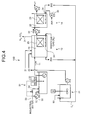
- FIG. 4 An apparatus for treating a radioactive nitrate waste liquid according to a fourth embodiment of the present invention is explained with reference to Fig. 4 .
- the apparatus for treating a radioactive nitrate waste liquid according to the present embodiment is configured substantially identical to the apparatus for treating a radioactive nitrate waste liquid according to the first embodiment shown in Fig. 1 , and thus like reference letters or numerals are denoted to like constituent elements of the apparatus for treating a radioactive nitrate waste liquid according to the first embodiment shown in Fig. 1 , and redundant explanations thereof will be omitted.
- Fig. 4 is a schematic diagram of a configuration of the apparatus for treating a radioactive nitrate waste liquid according to the fourth embodiment of the present invention. As shown in Fig.
- an adjusting tank 51 that supplies a nitrate waste liquid (undiluted: salt concentration of 30 to 40%) 50 is arranged at an upstream of the denitrification tank 12 of the apparatus 10A for treating a radioactive nitrate waste liquid according to the first embodiment shown in Fig. 1 .
- the adjusting tank 51 includes an electrical conductivity meter (EC meter) 52 that measures a level of electric conductivity, an industrial-water introducing line 53, and an industrial-water supply-amount adjusting valve 54 which is arranged in the industrial-water introducing line 53 and which adjusts a flow rate of water to be diluted based on a measurement value of the electrical conductivity meter 52.
- EC meter electrical conductivity meter
- the industrial-water supply-amount adjusting valve 54 arranged in the industrial-water introducing line 53 is controlled based on the EC value measured by the electrical conductivity meter (EC meter) 52 arranged in the adjusting tank 51 to adjust the flow rate of water supplied to the adjusting tank 51. Specifically, when the EC value measured by the electrical conductivity meter (EC meter) 52 is high, the industrial-water supply-amount adjusting valve 54 is opened, and when the EC value measured by the electrical conductivity meter (EC meter) 52 is low, the industrial-water supply-amount adjusting valve 54 is closed.
- a control range of an EC value measured by the electrical conductivity meter (EC meter) 52 at this time is preferably from 50 to 70 mS/cm, and more preferably from 53 to 68 mS/cm.
- a nitrate-waste-liquid supplying pump P 4 is arranged in a nitrate-waste-liquid supplying line 55 that feeds the nitrate waste liquid 50 (undiluted liquid) to the adjusting tank 51. Based on the EC value measured by the electrical conductivity meter (EC meter) 52, the nitrate-waste-liquid supplying pump P 4 is controlled, and a supply amount of the nitrate waste liquid 50 (undiluted liquid) to be fed to the adjusting tank 51 is thus adjusted.
- the nitrate-waste-liquid supplying pump P 4 is stopped to halt supplying of the undiluted nitrate waste liquid 50 to the adjusting tank 51, and when the EC value measured by the electrical conductivity meter (EC meter) 52 is low, the nitrate-waste-liquid supplying pump P 4 is operated and the nitrate waste liquid 50 (undiluted liquid) is supplied to the adjusting tank 51.
- the concentration of a high-concentration nitrate waste liquid from treatment facilities is not always constant, and thus, even when the concentration of the nitrate waste liquid (undiluted liquid) 50 is not constant, it is possible to prevent transferring variation of the salt concentration in the nitrate waste liquid (undiluted liquid) 50 to the denitrification tank 12. This makes it possible to prevent a significant decrease in denitrification performance caused when the salt concentration is greatly varied.
- the nitrate waste liquid (diluted solution) 11 with a constant salt concentration can be supplied to the denitrification tank 12 via the nitrate-waste-liquid supplying pump P 5 , and thus the denitrification performance can be stabilized.
- FIG. 5 A biological treatment system using the apparatus for treating a radioactive nitrate waste liquid according to a fifth embodiment of the present invention is explained with reference to Fig. 5 .
- the apparatus for treating a radioactive nitrate waste liquid according to the present embodiment any one of the apparatuses for treating a radioactive nitrate waste liquid according to the first to fourth embodiments shown in Figs. 1 to 4 can be used, and thus explanations thereof will be omitted.
- Fig. 5 As shown in Fig.
- the biological treatment system 60 includes a diluter 62 that dilutes the nitrate waste liquid (undiluted liquid) 50 with industrial water 61, a biological treatment device (any one of the apparatuses for treating a radioactive nitrate waste liquid according to the first to fourth embodiments) 63 in which nitrate ions in the diluted nitrate waste liquid 11 are microbially treated for reduction with nitrogen and reaeration, a sludge dewatering device 67 that separates sludge 65 and a treated liquid 70 from the biologically treated liquid treated in the biological treatment device 63 and dewaters the separated sludge 65, and an incinerator 69 that incinerates dewatered sludge 68.
- a biological treatment device any one of the apparatuses for treating a radioactive nitrate waste liquid according to the first to fourth embodiments
- a sludge dewatering device 67 that separates sludge 65 and a treated liquid 70 from the biologically treated liquid treated in
- the diluter 62 operates in the adjusting tank 51 that dilutes an undiluted liquid as shown in Fig. 4 corresponding to the fourth embodiment described above.
- the biological treatment device 63 is an apparatus for treating a radioactive nitrate waste liquid configured by the denitrification tank 12 having the sludge dissolution tank 81 and the reaeration tank 14.
- the sludge dewatering device 67 dewaters the redundant sludge discharged from the denitrification tank and the reaeration tank of the biological treatment device 63.
- the incinerator 69 incinerates the dewatered sludge 68 or secondary waste discharged from the sludge dewatering device 67 into incinerated ashes 71.
- the biological treatment device 63 that biologically treats the nitrate waste liquid having a high salt concentration
- the salt concentration in the water that adheres to the sludge is high, and thus an amount of secondary waste (incinerated ashes) occasionally increases.
- the redundant sludge dewatering device 67 the industrial water 61 is added to flush the adhered liquid having a high salt concentration, and flushed cleansing water 72 is used as diluting water in the diluter 62 that dilutes the nitrate waste liquid 11.
- the amount of the secondary waste (incinerated ashes) can be decreased to about 1/2.
- a waste liquid with a high nitrate concentration discharged from nuclear facilities such as a reprocessing plant can be microbially treated efficiently, and minute sludge can be prevented from flowing out with a treated liquid.
Landscapes
- Life Sciences & Earth Sciences (AREA)
- Engineering & Computer Science (AREA)
- Chemical & Material Sciences (AREA)
- Water Supply & Treatment (AREA)
- Microbiology (AREA)
- Organic Chemistry (AREA)
- Environmental & Geological Engineering (AREA)
- Hydrology & Water Resources (AREA)
- Biodiversity & Conservation Biology (AREA)
- High Energy & Nuclear Physics (AREA)
- Molecular Biology (AREA)
- General Engineering & Computer Science (AREA)
- Physics & Mathematics (AREA)
- General Health & Medical Sciences (AREA)
- Biomedical Technology (AREA)
- Health & Medical Sciences (AREA)
- Chemical Kinetics & Catalysis (AREA)
- Purification Treatments By Anaerobic Or Anaerobic And Aerobic Bacteria Or Animals (AREA)
- Separation Using Semi-Permeable Membranes (AREA)
- Activated Sludge Processes (AREA)
- Treatment Of Sludge (AREA)
Abstract
Description
- The present invention relates to an apparatus for treating a radioactive nitrate waste liquid capable of reducing nitrate contained in waste water.
- A nitrate waste liquid generated from nuclear facilities such as a reprocessing plant has high concentration (salt concentration of equal to or more than 1%) as well as being radioactive. Therefore, the nitrate waste liquid cannot be discharged as it is, and is finally cast into a cement-solidified form and disposed underground.
- In recent years, there has been a concern that when the cement-solidified form contains nitrate, the nitrate may leak and pollute surrounding ground water and soil environment and thus dissolution of the nitrate is studied.
- There are various methods for treating nitrate such as an electric reduction method, a chemical reduction method, and a biological reduction method. The electric reduction method has problems such as inhibition by heavy metals and generation of ammonia.
Besides, the chemical reduction method has problems such as exothermic reaction and generation of ammonia. - On the other hand, the biological reduction method allows treatment at an ordinary temperature and pressure and there is no generation of ammonia. Accordingly, the method of treating nitrate by using the biological treatment has been studied (Patent Document 1). However, in the method of Patent Document 1, only one type of carbon source is used, so the method has problems such that the amount of redundant sludge generated with the nitrate reduction treatment is increased and a secondary waste disposal expense is increased.
-
Fig. 6 is a schematic diagram of a configuration of a conventional apparatus for treating a radioactive nitrate waste liquid utilizing an organism.
As shown inFig. 6 , aconventional apparatus 100 for treating a radioactive nitrate waste liquid includes adenitrification tank 102 that reduces nitrate, which is present in anitrate waste liquid 101 generated from nuclear facilities (not shown), to nitrogen gas, areaeration tank 104 that aerates and mixes adenitrified liquid 103 obtained by denitrification with active sludge, and aprecipitation tank 108 that separates a reaeratedliquid 105 that is a denitrification-treated liquid discharged from thereaeration tank 104 intoprecipitated sludge 106 and a treatedliquid 107. - The
denitrification tank 102 includes active sludge containing a large amount of denitrifying bacteria (not shown). In thedenitrification tank 102, nitrate ions in a nitrate waste liquid are reduced to nitrogen gas (N2) according to a reaction based on the following formula (1) by an action of an anaerobic microorganism (denitrifying bacteria) and are removed from the nitrate waste liquid.
At this time, acarbon source 121 such as methanol and apH adjuster 120 are supplied to thedenitrification tank 102. Further, amixer 110 is used to mix inside thedenitrification tank 102.
NO3 -+5/6CH3OH→1/2N2+5/6CO2+7/6H2O+OH- (1)
- Thereafter, the reaerated
liquid 105 passes through theprecipitation tank 108 from thereaeration tank 104, and is sent as a treatedliquid 107 to a subsequent process (not shown). Thesludge 106 precipitated in theprecipitation tank 108 is recovered asredundant sludge 131 by a circulatingpump 111. Further, a part of thesludge 106 precipitated in theprecipitation tank 108 is returned to thedenitrification tank 102 via a returned-sludge supplying line 112 and is reused. The sludge not reused is removed from a system as theredundant sludge 131 and is sent to a disposing process (not shown). - Further, there is used a method and an apparatus for treating a nitrate-containing waste liquid. The method includes a microbial treatment process of reducing nitrate nitrogen and nitrite nitrogen to nitrogen by using anaerobic denitrifying bacteria in microorganism-containing sludge, and the apparatus includes a plurality of treatment tanks (Patent Document 2).
- Patent Document 1: Japanese Patent No.
3697037
Patent Document 2: Japanese Patent Application Laid-open No.2007-105627 - However, in the
conventional apparatus 100 for treating a nitrate waste liquid, when the concentration of nitrate in thenitrate waste liquid 101 is low (salt concentration is less than 1%), the denitrifying bacteria is not perished; however, when the concentration of nitrate in thenitrate waste liquid 101 is high (for example, about 1 to 7%), there is a problem that the denitrifying bacteria may be perished due to a rise in pH with the biological denitrification reaction. - Further, there is also the following problem. That is, when the concentration of nitrate in the
nitrate waste liquid 101 is high (for example, about 1 to 7%), water seeps from a living organism due to a rise in an osmotic pressure, its biology cannot be maintained and the living organism is perished. Therefore, a minute sludge floc is generated and thesludge 106 does not precipitate in theprecipitation tank 108, resulting in thesludge 106 flowing backwards with the treatedliquid 107. - Still another problem is that, when the
carbon source 121 supplied in the denitrification tank 102 (for example, organic acid such as acetic acid or sweetener) is changed, there occurs a multiplication of microorganisms, an increase in the generated amount ofredundant sludge 131, and an increase in the amount of disposal. - There is also a problem for nuclear facilities that the increased generated amount of the
redundant sludge 131 leads to huge expenses for disposal, because a secondary waste is disposed underground as a solidified form. That is, there is a problem that the amount of the secondary waste needs to be decreased. - Facilities that treat a radioactive nitrate waste liquid need to be installed within a controlled area for radiation, and thus there is a demand for making the treatment facilities compact.
- In addition, there is a demand that the amount of secondary waste needs to be reduced.
- Furthermore, as a microbial treatment system to be installed within a controlled area for radiation, there is a demand that it is needed to stabilize reactions and performances.
- In view of the above problems, an object of the present invention is to provide an apparatus for treating a radioactive nitrate waste liquid, which is installed within a controlled area for radiation and is capable of effectively microbially treating a waste liquid with a high nitrate concentration.
- According to an aspect of the present invention, an apparatus for treating a radioactive nitrate waste liquid includes: a denitrification tank that accommodates active sludge which adsorbs or takes in a radioactive substance in a nitrate waste liquid containing nitrate and the radioactive substance and in which an anaerobic microorganism that reduces the nitrate to nitrogen gas grows; a reaeration tank that aerates and mixes a denitrification-treated liquid treated in the denitrification tank with the active sludge in which the aerobic microorganism grows; and a sludge dissolution tank that dissolves redundant sludge discharged from the denitrification tank and the reaeration tank. A sludge solvent is supplied to the sludge dissolution tank to dissolve redundant sludge, and a sludge lysate is supplied to the denitrification tank as a carbon source.
- Advantageously, in the apparatus for treating a radioactive nitrate waste liquid, the sludge solvent is acetic peracid or a nitrate waste liquid of which pH is equal to or more than 12.
- According to another aspect of the present invention, an apparatus for treating a radioactive nitrate waste liquid includes: a denitrification tank that accommodates active sludge which adsorbs or takes in a radioactive substance in a nitrate waste liquid containing nitrate and the radioactive substance and in which an anaerobic microorganism that reduces the nitrate to nitrogen gas grows; a reaeration tank that aerates and mixes a denitrification-treated liquid treated in the denitrification tank with the active sludge in which the aerobic microorganism grows; and a sludge dissolution tank that dissolves redundant sludge discharged from the denitrification tank and the reaeration tank. Acetic peracid is supplied to the sludge dissolution tank to dissolve redundant sludge, a sludge lysate is supplied to the denitrification tank as a carbon source, and acetic acid is supplied to the denitrification tank.
- According to still another aspect of the present invention, an apparatus for treating a radioactive nitrate waste liquid includes: a denitrification tank that accommodates active sludge which adsorbs or takes in a radioactive substance in a nitrate waste liquid containing nitrate and the radioactive substance and in which an anaerobic microorganism that reduces the nitrate to nitrogen gas grows; a reaeration tank that aerates and mixes a denitrification-treated liquid treated in the denitrification tank with the active sludge in which the aerobic microorganism grows; and a sludge dissolution tank that dissolves redundant sludge discharged from the denitrification tank and the reaeration tank. A nitrate waste liquid of which pH is equal to or more than 12 is supplied to the sludge dissolution tank to dissolve redundant sludge, a sludge lysate is supplied to the denitrification tank as a carbon source, and a nitrate waste liquid is supplied to the denitrification tank.
- Advantageously, in the apparatus for treating a radioactive nitrate waste liquid, the denitrification tank includes: a pH adjusting unit that supplies a pH adjuster used for adjusting pH of the nitrate waste liquid; a first solid-liquid separating unit that separates a denitrified liquid treated with the active sludge into a solid content containing sludge and a denitrification-treated liquid; and a gas supplying unit that is arranged on a lower side of the first solid-liquid separating unit and supplies gas not containing oxygen into the denitrification tank, and the reaeration tank includes: a second solid-liquid separating unit that further separates the denitrification-treated liquid treated with the active sludge into redundant sludge and a treated liquid; and an air supplying unit that is arranged on a lower side of the second solid-liquid separating unit and supplies air into the reaeration tank.
- Advantageously, in the apparatus for treating a radioactive nitrate waste liquid, pH of the denitrified liquid in the denitrification tank is from 7.0 to 10.0.
- Advantageously, in the apparatus for treating a radioactive nitrate waste liquid, the denitrification tank includes a gas circulating line through which nitrogen gas and carbon dioxide gas produced by a reaction between the aerobic microorganism and the nitrate in the denitrified liquid are circulated into the denitrification tank.
- Advantageously, in the apparatus for treating a radioactive nitrate waste liquid, the first solid-liquid separating unit and the second solid-liquid separating unit are solid-liquid separating films.
- Advantageously, the apparatus for treating a radioactive nitrate waste liquid further includes a total-organic-carbon measuring device that analyzes organic carbon in a nitrate waste liquid discharged from the sludge dissolution tank, and a total-nitrogen measuring device that measures an amount of nitrogen in a nitrogen compound in a nitrate waste liquid discharged from the sludge dissolution tank.
- Advantageously, the apparatus for treating a radioactive nitrate waste liquid includes: an adjusting tank at an upstream of the denitrification tank. The adjusting tank includes: an electrical conductivity (EC) meter that measures a level of electric conductivity; an industrial-water introducing line; and an industrial-water supply-amount adjusting valve that is interposed through the industrial-water introducing line and adjusts an industrial-water supply amount based on a measurement value of the electrical conductivity meter.
- According to the present invention, a part of redundant sludge is supplied to a sludge dissolution tank, and the supplied sludge is decomposed by using acetic peracid or the like as a sludge solvent. Because a multiplied microorganism is perished and the perished microorganism is an organic substance, the decomposed material can be used as a carbon source that is supplied to a denitrification tank.
- Further, the present invention includes a first solid-liquid separating unit that separates a denitrified liquid treated with active sludge in a denitrification tank into a sludge-containing solid content and a denitrification-treated liquid, and a second solid-liquid separating unit that further separates a reaerated liquid treated in a reaeration tank into a sludge-containing solid content and a reaeration-treated liquid. Therefore, minute sludge can be prevented from flowing out with a treated liquid.
-
- [
Fig. 1] Fig. 1 is a conceptual diagram of an apparatus for treating a radioactive nitrate waste liquid according to a first embodiment of the present invention. - [
Fig. 2] Fig. 2 is a schematic diagram of a configuration of an apparatus for treating a radioactive nitrate waste liquid according to a second embodiment of the present invention. - [
Fig. 3] Fig. 3 is a schematic diagram of a configuration of an apparatus for treating a radioactive nitrate waste liquid according to a third embodiment of the present invention. - [
Fig. 4] Fig. 4 is a schematic diagram of a configuration of an apparatus for treating a radioactive nitrate waste liquid according to a fourth embodiment of the present invention. - [
Fig. 5] Fig. 5 is a schematic diagram of a configuration of a biological treatment system using an apparatus for treating a radioactive nitrate waste liquid according to a fifth embodiment of the present invention. - [
Fig. 6] Fig. 6 is a schematic diagram of a configuration of a conventional apparatus for treating a radioactive nitrate waste liquid utilizing an organism. -
- 10A to 10D
- apparatus for treating radioactive nitrate waste liquid
- 11
- nitrate waste liquid
- 12
- denitrification tank
- 14
- reaeration tank
- 21
- pH adjuster
- 22
- carbon source
- 23
- denitrified liquid
- 24
- denitrification-treated liquid
- 25
- first solid-liquid separating film
- 26A, 26B
- solid content (redundant sludge)
- 27
- reaeration-treated liquid
- 28
- second solid-liquid separating film
- 29
- reaerated liquid
- 30
- gas supplying unit
- 31
- gas discharge line
- 34
- air supplying unit
- 35
- blower
- 51
- adjusting tank
- 52
- electrical conductivity meter (EC meter)
- 53
- industrial-water introducing line
- 54
- industrial-water supply-amount adjusting valve
- 55
- nitrate-waste-liquid supplying line
- 61
- industrial water
- 62
- diluter
- 63
- biological treatment device
- 65
- sludge
- 67
- sludge dewatering device
- 68
- dewatered sludge
- 69
- incinerator
- 70
- treated liquid
- 71
- incinerated ashes
- 72
- cleansing water
- 81
- sludge dissolution tank
- Exemplary embodiments of the present invention will be explained below in detail with reference to the accompanying drawings. Note that the present invention is not limited to the embodiments. In addition, constituent elements in the embodiments include those that can be easily assumed by those skilled in the art or that are substantially equivalent.
- An apparatus for treating a radioactive nitrate waste liquid according to an embodiment of the present invention is explained with reference to the drawings.
-
Fig. 1 is a conceptual diagram of the apparatus for treating a radioactive nitrate waste liquid according to a first embodiment of the present invention. - As shown in
Fig. 1 , anapparatus 10A for treating a radioactive nitrate waste liquid according to the present embodiment is an apparatus for treating a radioactive nitrate waste liquid that includes adenitrification tank 12 which accommodates active sludge that adsorbs or takes in a radioactive substance in anitrate waste liquid 11 containing nitrate and the radioactive substance and in which an anaerobic microorganism that reduces the nitrate to nitrogen gas grows, and areaeration tank 14 that aerates and mixes a denitrification-treatedliquid 24 treated in thedenitrification tank 12 with the active sludge in which an aerobic microorganism grows. Theapparatus 10A includes asludge dissolution tank 81 that dissolvesredundant sludge denitrification tank 12 and thereaeration tank 14. In theapparatus 10A,acetic peracid 80 is supplied as a sludge solvent to thesludge dissolution tank 81 thereby to dissolve the redundant sludge, and a sludge lysate is supplied as acarbon source 22 to thedenitrification tank 12. - The
denitrification tank 12 includes a pH adjusting unit (not shown) that supplies apH adjuster 21 used for adjusting pH of thenitrate waste liquid 11, a carbon-source supplying unit (not shown) that supplies thecarbon source 22 to thedenitrification tank 12, a first solid-liquid separating film 25 as a first solid-liquid separating unit that separates a denitrified liquid 23 treated with the active sludge into a solid content containing the sludge (theredundant sludge 26A) and a treated liquid, and agas supplying unit 30 that is arranged on a lower side of the first solid-liquid separating film 25 and supplies gas not containing oxygen (for example, one or both of nitrogen gas (N2) and carbon dioxide gas (CO2)) into thedenitrification tank 12. Thereaeration tank 14 includes a second solid-liquid separating film 28 that reaerates the denitrification-treatedliquid 24 treated with the active sludge to further separate a reaerated liquid 29 into theredundant sludge 26B and a reaeration-treatedliquid 27, and anair supplying unit 34 that is arranged on a lower side of the second solid-liquid separating film 28 as a second solid-liquid separating unit and uses ablower 35 to supply air into thereaeration tank 14.
At a lower portion of the first solid-liquid separating film 25 and the second solid-liquid separating film 28, thegas supplying unit 30 and theair supplying unit 34 are arranged, respectively. When the supplied gas rises, a liquid mixed with the active sludge passes through surfaces of the separating films, and at this time, the liquid only permeates the films, and a solid-liquid separation is performed in this way. The active sludge that is left after the separation adheres to the film surface; however, the film surface is always cleansed with a flow of the supplied gas. As a result, the active sludge that adheres to the film surface is cleansed and reduced. This makes it possible to perform a solid-liquid separation by using the film surface that is always clean. InFig. 1 , reference character P1 denotes a denitrification-treated-liquid supplying pump that supplies the denitrification-treatedliquid 24 to thereaeration tank 14 and reference character P2 denotes a reaeration-treated-liquid supplying pump that sends the reaeration-treatedliquid 27. - In the present embodiment, parts of the
redundant sludge denitrification tank 12 and thereaeration tank 14 are supplied to thesludge dissolution tank 81 through a redundant-sludge supplying line L1, and by using theacetic peracid 80 as the sludge solvent, the supplied parts are decomposed in thetank 81. Because the multiplied microorganism is perished and the perished microorganism is an organic substance, the decomposed material can be used as thecarbon source 22 that is supplied to thedenitrification tank 12 through a supplying pump P3. - As the sludge solvent, the
acetic peracid 80 is used, and thus, as a result of the decomposition, acetic acid is produced. The produced acid also is used as thecarbon source 22, and therefore this eliminates necessity of additional carbon source or reduces addition of the carbon source.
That is, a material that originally contributes to a denitrification reaction can be obtained from the redundant sludge. Thus, in addition to a fact that theacetic peracid 80 is used for dissolution of the redundant sludge, the organic substance from the decomposed material and the acetic acid can be used as thecarbon source 22 for thedenitrification tank 12. Therefore, an effective utilization is achieved.
To perish the microorganism, substances such as chlorine and ozone can be used besides the acetic peracid. However, although these substances contribute to dissolution of the redundant sludge, they cannot be supplied to the denitrification tank after the dissolution and cause only adverse effects. Therefore, these substances are not preferable. - After the dissolution, the redundant sludge is re-used as the carbon source, and emitted as carbon dioxide gas. As a result, it is possible to decrease the generated amount of secondary waste.
- Further, in the
apparatus 10A for treating a radioactive nitrate waste liquid according to the present embodiment, the first solid-liquid separating film 25 and the second solid-liquid separating film 27 are respectively arranged in thedenitrification tank 12 and thereaeration tank 14. Accordingly, the minute sludge can be completely separated into the denitrified liquid 23 or thereaerated liquid 29. This can prevent the sludge from flowing out. Although not limited thereto, examples of types of the first solid-liquid separating film 25 and the second solid-liquid separating film 28 include well-known solid-liquid separating films such as a flat film and a hollow fiber film. - As a result, when the minute sludge is completely separated from the denitrification-treated
liquid 24 or the reaeration-treatedliquid 27, it is possible to decrease the concentration of suspended solid (SS) of the discharged reaeration-treatedliquid 27. - When the first solid-
liquid separating film 25 is installed within thedenitrification tank 12, it is possible to prevent denitrifying bacteria from flowing out, and there is no contamination of any other bacteria. Thus, only a large amount of denitrifying bacteria multiplied within thedenitrification tank 12 exist in the tank. As a result, a sufficient amount of sludge can be secured, and the sludge concentration within thedenitrification tank 12 can be maintained at a high level. Accordingly, a high-level denitrification performance of thedenitrification tank 12 can be maintained and the apparatus can be made compact. - A high concentration level of the sludge within the
denitrification tank 12 can be maintained, and thus the denitrification performance of thedenitrification tank 12 can be enhanced and the apparatus can be made compact. - When the first solid-
liquid separating film 25 and the second solid-liquid separating film 27 are arranged, a particulate radioactive substance contained in thenitrate waste liquid 11 can be also separated from thereaeration liquid 29. Thus, it is possible to decrease the radioactive concentration of the reaeration-treatedliquid 27 discharged to outside and to decrease the radioactive concentration of the reaeration-treatedliquid 27. - In the
apparatus 10A for treating a radioactive nitrate waste liquid according to the present embodiment, the pH of the denitrified liquid 23 in thedenitrification tank 12 is preferably adjusted between 7.0 and 10.0. It is preferable that the pH is from 8.0 to 9.5, and more preferably the pH is from 8.0 to 9.0. This is because when the pH of the denitrifiedliquid 23 exceeds 10.0, the microorganism is perished. Moreover, when the pH is less than 7.0, a reaction rate for a treatment for reducing the nitrogen gas in the microorganism is decreased. - In the
apparatus 10A for treating a radioactive nitrate waste liquid according to the present embodiment, thegas supplying unit 30 is arranged on a lower side (bottom surface side of the tank) of the first solid-liquid separating film 25 of thedenitrification tank 12 so as to supply gas not containing oxygen (for example, nitrogen gas) to the denitrifiedliquid 23 of thedenitrification tank 12. This is because when there is oxygen in thenitrate waste liquid 11, the reaction in the process for reducing nitrogen gas in the anaerobic microorganism is not progressed preferably. - By supplying nitrogen gas into the denitrified liquid 23 in the
denitrification tank 12 via thegas supplying unit 30, the denitrified liquid 23 in thedenitrification tank 12 can be forcedly stirred and the treatment for reducing the nitrogen gas by the microorganisms can be accelerated. Moreover, when nitrogen gas is supplied via thegas supplying unit 30 from below the first solid-liquid separating film 25, the active sludge that adheres to the first solid-liquid separating film 25 can be reduced. As a result, due to a gas cleansing effect, clogging of the film can be prevented. - In the
apparatus 10A for treating a radioactive nitrate waste liquid according to the present embodiment, nitrogen gas (N2 gas) is supplied by the gas supplying unit. However, the present invention is not limited thereto, and any gas that does not contain oxygen, such as carbon dioxide gas (CO2 gas) and an inactive gas, can be used. - Further, in the
apparatus 10A for treating a radioactive nitrate waste liquid according to the present embodiment, nitrogen gas (N2) and carbon dioxide gas (CO2) generated in thedenitrification tank 12 are released to outside via a gas discharge line 31A. - In the
apparatus 10A for treating a radioactive nitrate waste liquid according to the present embodiment, initially, the sludge used in sewage sludge or an industrial waste treatment is put in as seed sludge and active sludge multiplied until the active sludge concentration reaches, for example, about 5,000 to 20,000 mg/L, can be used. While the active sludge can be held by a granular carrier or a fibrous carrier, in the exemplary embodiments of the present invention, various types of such carriers are not used, and floating active sludge is preferably used. - In the
apparatus 10A for treating a radioactive nitrate waste liquid according to the present embodiment, the decomposed material obtained from the redundant sludge can be used as thecarbon source 22. When thecarbon source 22 is separately supplied from outside, although the present invention is not limited thereto, organic acid can be used as thecarbon source 22. - In the
apparatus 10A for treating a radioactive nitrate waste liquid according to the present embodiment, although the present invention is not limited thereto, examples of thepH adjuster 21 include sulfuric acid and hydrochloric acid. - In the
apparatus 10A for treating a radioactive nitrate waste liquid according to the present embodiment, as the microorganism contained in the active sludge in thedenitrification tank 12, a well-known anaerobic microorganism that exhibits a denitrification performance can be used. Although not particularly limited thereto, in thereaeration tank 14, a well-known aerobic microorganism for a reaeration can be used. - In the
apparatus 10A for treating a radioactive nitrate waste liquid according to the present embodiment, the solid-liquid separating film is used as a solid-liquid separating unit; however, the present invention is not limited thereto, and any unit that can separate the sludge and the liquid can be used. - As described above, in the
apparatus 10A for treating a radioactive nitrate waste liquid according to the present embodiment, parts of theredundant sludge sludge dissolution tank 81, and by using theacetic peracid 80 as a sludge solvent, the supplied sludge is decomposed in thetank 81. Because the multiplied microorganism is perished and the perished microorganism is an organic substance, the decomposed material can be used as thecarbon source 22 that is supplied to thedenitrification tank 12.
Theacetic peracid 80 is used as a sludge solvent and, as a result of the decomposition, acetic acid is produced. The produced acetic acid also becomes thecarbon source 22, and therefore this eliminates necessity of additional carbon source or reduces addition of the carbon source. - Furthermore, the first solid-
liquid separating film 25 and the second solid-liquid separating film 28 are respectively arranged in thedenitrification tank 12 and thereaeration tank 14. Accordingly, the minute sludge can be completely separated into the denitrification-treatedliquid 24 and the reaeration-treatedliquid 27. Thus, the sludge can be prevented from flowing out. Moreover, the concentration of suspended solid (SS) in the reaeration-treatedliquid 27 that is discharged from thereaeration tank 14 and is separately treated can be improved. - Because a sufficient amount of sludge can be secured within the
denitrification tank 12, the sludge concentration within thedenitrification tank 12 can be maintained at a high level. Therefore, a high-level denitrification performance of thedenitrification tank 12 can be maintained and the apparatus can be made compact. - In the
denitrification tank 12, a gas circulating line (not shown) through which the nitrogen gas (N2) and the carbon dioxide gas (CO2) produced as a result of a reaction between the anaerobic microorganism and the nitrate in the denitrified liquid 23 are circulated within thedenitrification tank 12 is arranged and branched from a part of thegas discharge line 31. - As a result, the nitrogen gas (N2) and the carbon dioxide gas (CO2) generated in the
denitrification tank 12 are fed to thegas supplying unit 30 by using a blower interposed through a gas circulating line, and can be introduced into thedenitrification tank 12.
In this way, the nitrogen gas (N2) and the carbon dioxide gas (CO2) generated as a result of the microorganism reaction within thedenitrification tank 12 are re-circulated and re-used within the denitrification tank. Therefore, there is no need to separately arrange the nitrogen gas supplying unit (as shown inFig. 1 ) that supplies gas not containing oxygen. As a result, it is possible to eliminate the nitrogen gas supplying unit and to reduce gas purchasing costs. - By using the apparatus according to the present embodiment, a denitrification test was conducted on a nitrate waste liquid having an undiluted nitrate nitrogen concentration of 6700 to 9200 mg/L (salt concentration: 4.0 to 5.5%) by using methanol and acetic acid as a carbon source with a test temperature set to 20 to 25°C (room temperature).
When the first solid-liquid separating film was not arranged in the denitrification tank, the denitrification performance reached 2kg-N/m3/d, whereas when the first solid-liquid separating film was arranged in the denitrification tank, the denitrification performance was improved to 7kg-N/m3/d.
While the denitrification performance of 7kg-N/m3/d when the first solid-liquid separating film was arranged in the denitrification tank was maintained, the generated amount of redundant sludge was reduced to below 2/3 and an amount of carbon source to be added (acetic peracid + acetic acid) was reduced to below 1/2. - An apparatus for treating a radioactive nitrate waste liquid according to a second embodiment of the present invention is explained with reference to
Fig. 2 .
Anapparatus 10B for treating a radioactive nitrate waste liquid according to the present embodiment is configured substantially identical to theapparatus 10A for treating a radioactive nitrate waste liquid according to the first embodiment shown inFig. 1 , and thus like reference letters or numerals are denoted to like constituent elements of the apparatus for treating a radioactive nitrate waste liquid according to the first embodiment shown inFig. 1 , and redundant explanations thereof will be omitted.
Fig. 2 is a schematic diagram of a configuration of the apparatus for treating a radioactive nitrate waste liquid according to the second embodiment of the present invention. As shown inFig. 2 , theapparatus 10B for treating a radioactive nitrate waste liquid according to the present embodiment is configured to use a nitrate waste liquid (undiluted liquid) 83 having pH of equal to or more than 12 as the sludge solvent added to thesludge dissolution tank 81.
In the present embodiment, instead of acetic peracid, an alkaline (pH is equal to or more than 12) nitrate waste liquid (undiluted liquid) is used. Thus, theredundant sludge nitrate waste liquid 11 to thedenitrification tank 12, and the organic substance is utilized as the carbon source. - The nitrate waste liquid (undiluted liquid) 83 reduces its pH as a result of the dissolution of the
sludge dissolution tank 81. Accordingly, it is possible to reduce a usage amount of thepH adjuster 21 added in thedenitrification tank 12. - An apparatus for treating a radioactive nitrate waste liquid according to a third embodiment of the present invention is explained with reference to
Fig. 3 .
The apparatus for treating a radioactive nitrate waste liquid according to the present embodiment is configured substantially identical to the apparatus for treating a radioactive nitrate waste liquid according to the first embodiment shown inFig. 1 , and thus like reference numerals are denoted to like constituent elements of the apparatus for treating a radioactive nitrate waste liquid according to the first embodiment shown inFig. 1 , and redundant explanations thereof will be omitted.
Fig. 3 is a schematic diagram of a configuration of the apparatus for treating a radioactive nitrate waste liquid according to the third embodiment of the present invention.
As shown inFig. 3 , anapparatus 10C for treating a radioactive nitrate waste liquid according to the present embodiment includes a total-organic-carbon measuring device (TOC) 84 that analyzes an organic carbon in thenitrate waste liquid 11 discharged from thesludge dissolution tank 81 and a total-nitrogen measuring device (T-N) 85 that measures the amount of nitrogen in a nitrogen compound in thenitrate waste liquid 11. - Based on this measurement result, the amount of the
carbon source 22 separately added to thedenitrification tank 12 is adjusted to increase or decrease so that the value of the TOC/T-N is from 7.5 to 11 (in terms of C/N, 3.0 to 4.5).
Accordingly, there is no excessive supply of theexcessive carbon source 22 and an appropriate amount of the carbon source can be supplied, and thus a stable denitrification reaction can be performed.
Therefore, it becomes possible to decrease the amount of carbon source to be added and also to decrease the generated amount of secondary waste. - An apparatus for treating a radioactive nitrate waste liquid according to a fourth embodiment of the present invention is explained with reference to
Fig. 4 . The apparatus for treating a radioactive nitrate waste liquid according to the present embodiment is configured substantially identical to the apparatus for treating a radioactive nitrate waste liquid according to the first embodiment shown inFig. 1 , and thus like reference letters or numerals are denoted to like constituent elements of the apparatus for treating a radioactive nitrate waste liquid according to the first embodiment shown inFig. 1 , and redundant explanations thereof will be omitted.Fig. 4 is a schematic diagram of a configuration of the apparatus for treating a radioactive nitrate waste liquid according to the fourth embodiment of the present invention. As shown inFig. 4 , in anapparatus 10D for treating a radioactive nitrate waste liquid according to the present embodiment, an adjustingtank 51 that supplies a nitrate waste liquid (undiluted: salt concentration of 30 to 40%) 50 is arranged at an upstream of thedenitrification tank 12 of theapparatus 10A for treating a radioactive nitrate waste liquid according to the first embodiment shown inFig. 1 . The adjustingtank 51 includes an electrical conductivity meter (EC meter) 52 that measures a level of electric conductivity, an industrial-water introducing line 53, and an industrial-water supply-amount adjusting valve 54 which is arranged in the industrial-water introducing line 53 and which adjusts a flow rate of water to be diluted based on a measurement value of theelectrical conductivity meter 52. - The industrial-water supply-
amount adjusting valve 54 arranged in the industrial-water introducing line 53 is controlled based on the EC value measured by the electrical conductivity meter (EC meter) 52 arranged in the adjustingtank 51 to adjust the flow rate of water supplied to the adjustingtank 51.
Specifically, when the EC value measured by the electrical conductivity meter (EC meter) 52 is high, the industrial-water supply-amount adjusting valve 54 is opened, and when the EC value measured by the electrical conductivity meter (EC meter) 52 is low, the industrial-water supply-amount adjusting valve 54 is closed. - In the
apparatus 10D for treating a radioactive nitrate waste liquid according to the present embodiment, when a biological treatment is performed in a high salt concentration state of about 4%, for example, by diluting the nitrate waste liquid (undiluted: salt concentration of 30 to 40%), a control range of an EC value measured by the electrical conductivity meter (EC meter) 52 at this time is preferably from 50 to 70 mS/cm, and more preferably from 53 to 68 mS/cm. - In the
apparatus 10D for treating a radioactive nitrate waste liquid according to the present embodiment, a nitrate-waste-liquid supplying pump P4 is arranged in a nitrate-waste-liquid supplying line 55 that feeds the nitrate waste liquid 50 (undiluted liquid) to the adjustingtank 51. Based on the EC value measured by the electrical conductivity meter (EC meter) 52, the nitrate-waste-liquid supplying pump P4 is controlled, and a supply amount of the nitrate waste liquid 50 (undiluted liquid) to be fed to the adjustingtank 51 is thus adjusted.
Specifically, when the EC value measured by the electrical conductivity meter (EC meter) 52 is high, the nitrate-waste-liquid supplying pump P4 is stopped to halt supplying of the undilutednitrate waste liquid 50 to the adjustingtank 51, and when the EC value measured by the electrical conductivity meter (EC meter) 52 is low, the nitrate-waste-liquid supplying pump P4 is operated and the nitrate waste liquid 50 (undiluted liquid) is supplied to the adjustingtank 51. - As a result, the concentration of a high-concentration nitrate waste liquid from treatment facilities is not always constant, and thus, even when the concentration of the nitrate waste liquid (undiluted liquid) 50 is not constant, it is possible to prevent transferring variation of the salt concentration in the nitrate waste liquid (undiluted liquid) 50 to the
denitrification tank 12. This makes it possible to prevent a significant decrease in denitrification performance caused when the salt concentration is greatly varied. - Further, the nitrate waste liquid (diluted solution) 11 with a constant salt concentration can be supplied to the
denitrification tank 12 via the nitrate-waste-liquid supplying pump P5, and thus the denitrification performance can be stabilized. - A biological treatment system using the apparatus for treating a radioactive nitrate waste liquid according to a fifth embodiment of the present invention is explained with reference to
Fig. 5 .
As the apparatus for treating a radioactive nitrate waste liquid according to the present embodiment, any one of the apparatuses for treating a radioactive nitrate waste liquid according to the first to fourth embodiments shown inFigs. 1 to 4 can be used, and thus explanations thereof will be omitted.
As shown inFig. 5 , thebiological treatment system 60 according to the present embodiment includes adiluter 62 that dilutes the nitrate waste liquid (undiluted liquid) 50 withindustrial water 61, a biological treatment device (any one of the apparatuses for treating a radioactive nitrate waste liquid according to the first to fourth embodiments) 63 in which nitrate ions in the dilutednitrate waste liquid 11 are microbially treated for reduction with nitrogen and reaeration, asludge dewatering device 67 that separatessludge 65 and a treated liquid 70 from the biologically treated liquid treated in thebiological treatment device 63 and dewaters the separatedsludge 65, and anincinerator 69 that incinerates dewateredsludge 68. - The
diluter 62 operates in the adjustingtank 51 that dilutes an undiluted liquid as shown inFig. 4 corresponding to the fourth embodiment described above.
Thebiological treatment device 63 is an apparatus for treating a radioactive nitrate waste liquid configured by thedenitrification tank 12 having thesludge dissolution tank 81 and thereaeration tank 14.
Thesludge dewatering device 67 dewaters the redundant sludge discharged from the denitrification tank and the reaeration tank of thebiological treatment device 63. Theincinerator 69 incinerates the dewateredsludge 68 or secondary waste discharged from thesludge dewatering device 67 into incineratedashes 71. - In the
biological treatment device 63 that biologically treats the nitrate waste liquid having a high salt concentration, at the time of dewatering the redundant sludge, the salt concentration in the water that adheres to the sludge is high, and thus an amount of secondary waste (incinerated ashes) occasionally increases. For this, in the redundantsludge dewatering device 67, theindustrial water 61 is added to flush the adhered liquid having a high salt concentration, and flushed cleansingwater 72 is used as diluting water in thediluter 62 that dilutes thenitrate waste liquid 11. - Therefore, a part of the
industrial water 61 used in thediluter 62 is used for cleansing at the time of dewatering, and thus there is no need to use additionalindustrial water 61. Further, by decreasing the salt concentration in the adhering water, the amount of the secondary waste (incinerated ashes) can be decreased to about 1/2. - As described above, by using the apparatus for treating a radioactive nitrate waste liquid according to the present invention, a waste liquid with a high nitrate concentration discharged from nuclear facilities such as a reprocessing plant can be microbially treated efficiently, and minute sludge can be prevented from flowing out with a treated liquid.
Claims (10)
- An apparatus for treating a radioactive nitrate waste liquid, comprising:a denitrification tank that accommodates active sludge which adsorbs or takes in a radioactive substance in a nitrate waste liquid containing nitrate and the radioactive substance and in which an anaerobic microorganism that reduces the nitrate to nitrogen gas grows;a reaeration tank that aerates and mixes a denitrification-treated liquid treated in the denitrification tank with the active sludge in which the aerobic microorganism grows; anda sludge dissolution tank that dissolves redundant sludge discharged from the denitrification tank and the reaeration tank, whereina sludge solvent is supplied to the sludge dissolution tank to dissolve redundant sludge, and a sludge lysate is supplied to the denitrification tank as a carbon source.
- The apparatus for treating a radioactive nitrate waste liquid according to claim 1, wherein the sludge solvent is acetic peracid or a nitrate waste liquid the pH of which is equal to or more than 12.
- An apparatus for treating a radioactive nitrate waste liquid, comprising:a denitrification tank that accommodates active sludge which adsorbs or takes in a radioactive substance in a nitrate waste liquid containing nitrate and the radioactive substance and in which an anaerobic microorganism that reduces the nitrate to nitrogen gas grows;a reaeration tank that aerates and mixes a denitrification-treated liquid treated in the denitrification tank with the active sludge in which the aerobic microorganism grows; anda sludge dissolution tank that dissolves redundant sludge discharged from the denitrification tank and the reaeration tank, whereinacetic peracid is supplied to the sludge dissolution tank to dissolve redundant sludge, a sludge lysate is supplied to the denitrification tank as a carbon source, and acetic acid is supplied to the denitrification tank.
- An apparatus for treating a radioactive nitrate waste liquid, comprising:a denitrification tank that accommodates active sludge which adsorbs or takes in a radioactive substance in a nitrate waste liquid containing nitrate and the radioactive substance and in which an anaerobic microorganism that reduces the nitrate to nitrogen gas grows;a reaeration tank that aerates and mixes a denitrification-treated liquid treated in the denitrification tank with the active sludge in which the aerobic microorganism grows; anda sludge dissolution tank that dissolves redundant sludge discharged from the denitrification tank and the reaeration tank, whereina nitrate waste liquid the pH of which is equal to or more than 12 is supplied to the sludge dissolution tank to dissolve redundant sludge, a sludge lysate is supplied to the denitrification tank as a carbon source, and a nitrate waste liquid is supplied to the denitrification tank.
- The apparatus for treating a radioactive nitrate waste liquid according to any one of claims 1 to 4, wherein
the denitrification tank comprises:a pH adjusting unit that supplies a pH adjuster used for adjusting pH of the nitrate waste liquid;a first solid-liquid separating unit that separates a denitrified liquid treated with the active sludge into a solid content containing sludge and a denitrification-treated liquid; anda gas supplying unit that is arranged on a lower side of the first solid-liquid separating unit and supplies gas not containing oxygen into the denitrification tank, andthe reaeration tank comprises:a second solid-liquid separating unit that further separates the denitrification-treated liquid treated with the active sludge into redundant sludge and a treated liquid; andan air supplying unit that is arranged on a lower side of the second solid-liquid separating unit and supplies air into the reaeration tank. - The apparatus for treating a radioactive nitrate waste liquid according to any one of claims 1 to 5, wherein pH of the denitrified liquid in the denitrification tank is from 7.0 to 10.0.
- The apparatus for treating a radioactive nitrate waste liquid according to claim 1 or 2, wherein the denitrification tank includes a gas circulating line through which nitrogen gas and carbon dioxide gas produced by a reaction between the aerobic microorganism and the nitrate in the denitrified liquid are circulated into the denitrification tank.
- The apparatus for treating a radioactive nitrate waste liquid according to claim 5, wherein the first solid-liquid separating unit and the second solid-liquid separating unit are solid-liquid separating films.
- The apparatus for treating a radioactive nitrate waste liquid according to claim 4, further comprising:a total-organic-carbon measuring device that analyzes organic carbon in a nitrate waste liquid discharged from the sludge dissolution tank, anda total-nitrogen measuring device that measures an amount of nitrogen in a nitrogen compound in a nitrate waste liquid discharged from the sludge dissolution tank.
- The apparatus for treating a radioactive nitrate waste liquid according to any one of claims 1 to 9, comprising
an adjusting tank at an upstream of the denitrification tank, wherein
the adjusting tank comprises:an electrical conductivity (EC) meter that measures a level of electric conductivity;an industrial-water introducing line; andan industrial-water supply-amount adjusting valve that is interposed through the industrial-water introducing line and adjusts an industrial-water supply amount based on a measurement value of the electrical conductivity meter.
Applications Claiming Priority (2)
| Application Number | Priority Date | Filing Date | Title |
|---|---|---|---|
| JP2008029554A JP4774065B2 (en) | 2008-02-08 | 2008-02-08 | Radionitrate waste liquid treatment equipment |
| PCT/JP2009/052097 WO2009099209A1 (en) | 2008-02-08 | 2009-02-06 | Apparatus and method for treatment of radioactive nitrate salt liquid waste |
Publications (3)
| Publication Number | Publication Date |
|---|---|
| EP2242061A1 true EP2242061A1 (en) | 2010-10-20 |
| EP2242061A4 EP2242061A4 (en) | 2015-04-22 |
| EP2242061B1 EP2242061B1 (en) | 2016-04-20 |
Family
ID=40952277
Family Applications (1)
| Application Number | Title | Priority Date | Filing Date |
|---|---|---|---|
| EP09709223.3A Active EP2242061B1 (en) | 2008-02-08 | 2009-02-06 | Apparatus and method for treatment of radioactive nitrate salt liquid waste |
Country Status (4)
| Country | Link |
|---|---|
| US (1) | US8696892B2 (en) |
| EP (1) | EP2242061B1 (en) |
| JP (1) | JP4774065B2 (en) |
| WO (1) | WO2009099209A1 (en) |
Cited By (2)
| Publication number | Priority date | Publication date | Assignee | Title |
|---|---|---|---|---|
| US20140332463A1 (en) * | 2013-05-10 | 2014-11-13 | Ecolab Usa Inc. | Reduction of hydrogen sulfide and/or malodor gassing from water via the addition of peroxyacetic acid/hydrogen peroxide product |
| CN105293848A (en) * | 2015-11-20 | 2016-02-03 | 天津大学 | Method and device capable of dissolving sludge extracellular polymer to promote denitrification of sewage |
Families Citing this family (4)
| Publication number | Priority date | Publication date | Assignee | Title |
|---|---|---|---|---|
| CN105060623B (en) * | 2015-07-29 | 2017-04-05 | 吉林建筑大学 | Double dirt method for treating water based on hydrogenesis and acetogenesis/hydrogen autotrophic denitrification coupling |
| KR101792758B1 (en) | 2016-09-28 | 2017-11-01 | 롯데케미칼 주식회사 | Continuous treatment apparatus of waste organic solvent |
| JP6699792B2 (en) * | 2018-11-08 | 2020-05-27 | 王子ホールディングス株式会社 | Water treatment apparatus, dehydrated sludge production apparatus, water treatment method and dehydrated sludge production method |
| US11802067B2 (en) * | 2020-03-04 | 2023-10-31 | United States Government, as represented by the Administrator of the U.S. EPA | Nitrogen sparging assisted anoxic biological water treatment system |
Family Cites Families (12)
| Publication number | Priority date | Publication date | Assignee | Title |
|---|---|---|---|---|
| JP2896291B2 (en) * | 1993-06-14 | 1999-05-31 | 株式会社エイ・ティ・アール通信システム研究所 | Image display device |
| JP2600023Y2 (en) * | 1993-08-13 | 1999-09-27 | 大同ほくさん株式会社 | Wastewater treatment equipment |
| JP3697037B2 (en) | 1997-09-22 | 2005-09-21 | 中部電力株式会社 | Biological denitrification method |
| JP3828429B2 (en) * | 2002-01-30 | 2006-10-04 | レール・リキード−ソシエテ・アノニム・ア・ディレクトワール・エ・コンセイユ・ドゥ・スールベイランス・プール・レテュード・エ・レクスプロワタシオン・デ・プロセデ・ジョルジュ・クロード | Volume reduction method of excess sludge |
| MXPA06008671A (en) * | 2004-01-30 | 2007-02-16 | Univ Maryland Biotech Inst | Dissimilatory sulfate reduction as a process to promote denitrification in marine recirculating aquaculture systems. |
| JP2006015236A (en) * | 2004-07-01 | 2006-01-19 | Toray Ind Inc | Reclaimed water production apparatus and method |
| JP2007021285A (en) | 2005-07-12 | 2007-02-01 | Mitsubishi Rayon Eng Co Ltd | Surplus sludge volume reduction method and excess sludge volume reduction device |
| JP2007105627A (en) * | 2005-10-13 | 2007-04-26 | Mitsubishi Heavy Ind Ltd | Method for treating nitrate-containing waste liquid and device therefor |
| JP4859192B2 (en) * | 2005-12-09 | 2012-01-25 | 三菱重工環境・化学エンジニアリング株式会社 | Advanced sewage treatment method and system |
| JP2007271306A (en) * | 2006-03-30 | 2007-10-18 | Mitsubishi Heavy Ind Ltd | Cesium adsorbent and method for removing radionuclide |
| JP4625508B2 (en) * | 2008-02-08 | 2011-02-02 | 三菱重工業株式会社 | Nitrate waste liquid treatment method and apparatus |
| WO2009099208A1 (en) * | 2008-02-08 | 2009-08-13 | Mitsubishi Heavy Industries, Ltd. | Method and apparatus for treating radioactive nitrate waste liquid |
-
2008
- 2008-02-08 JP JP2008029554A patent/JP4774065B2/en active Active
-
2009
- 2009-02-06 WO PCT/JP2009/052097 patent/WO2009099209A1/en not_active Ceased
- 2009-02-06 US US12/811,896 patent/US8696892B2/en active Active
- 2009-02-06 EP EP09709223.3A patent/EP2242061B1/en active Active
Cited By (3)
| Publication number | Priority date | Publication date | Assignee | Title |
|---|---|---|---|---|
| US20140332463A1 (en) * | 2013-05-10 | 2014-11-13 | Ecolab Usa Inc. | Reduction of hydrogen sulfide and/or malodor gassing from water via the addition of peroxyacetic acid/hydrogen peroxide product |
| US8992780B2 (en) * | 2013-05-10 | 2015-03-31 | Ecolab Usa Inc | Reduction of hydrogen sulfide and/or malodor gassing from water via the addition of peroxyacetic acid/hydrogen peroxide product |
| CN105293848A (en) * | 2015-11-20 | 2016-02-03 | 天津大学 | Method and device capable of dissolving sludge extracellular polymer to promote denitrification of sewage |
Also Published As
| Publication number | Publication date |
|---|---|
| US8696892B2 (en) | 2014-04-15 |
| US20100276345A1 (en) | 2010-11-04 |
| EP2242061A4 (en) | 2015-04-22 |
| WO2009099209A1 (en) | 2009-08-13 |
| EP2242061B1 (en) | 2016-04-20 |
| JP2009186437A (en) | 2009-08-20 |
| JP4774065B2 (en) | 2011-09-14 |
Similar Documents
| Publication | Publication Date | Title |
|---|---|---|
| EP2239742B1 (en) | Method and apparatus for treating nitrate waste liquid | |
| US8409438B2 (en) | Apparatus and method for treating radioactive nitrate waste liquid | |
| US6387254B1 (en) | Apparatus for wastewater treatment | |
| EP2242061B1 (en) | Apparatus and method for treatment of radioactive nitrate salt liquid waste | |
| KR20140063454A (en) | Apparatus and method for treatment wastewater | |
| JP5581872B2 (en) | Method and apparatus for denitrification treatment of ammoniacal nitrogen waste liquid | |
| JP2007105631A (en) | Method and device for treating organic waste water | |
| JP5262735B2 (en) | Anaerobic treatment method and apparatus | |
| JP2015093258A (en) | Denitrification method and apparatus | |
| JP2012011376A (en) | Sewage treatment method and apparatus | |
| KR101294489B1 (en) | Apparatus for treating a drainage containing organic sulfur compounds | |
| JP2003311286A (en) | Method for cultivating dmf decomposing bacteria and method of effluent treatment | |
| JP2004275820A (en) | Wastewater treatment equipment | |
| JP2006075779A (en) | Sludge volume reduction device and method, and organic waste water treatment system | |
| JP2000070989A (en) | Method and apparatus for removing nitrogen from wastewater | |
| JP7050204B1 (en) | Wastewater treatment equipment and wastewater treatment method for wastewater containing high-concentration organic matter | |
| KR100202066B1 (en) | Wastewater Treatment Using Biological Three-Phase Digestion Process in a Single Reactor | |
| KR20010102737A (en) | Wastewater Treatment Method including Food Fermentation Process | |
| JP2007275846A (en) | Wastewater treatment system and wastewater treatment method | |
| JP4563121B2 (en) | Wastewater treatment method | |
| JP2007296436A (en) | Wastewater treatment method for wastewater containing high concentration organic matter | |
| JP2001047098A (en) | Wastewater and sludge treatment methods | |
| JP2000070987A (en) | Method and apparatus for removing phosphorus from wastewater | |
| JP2002219479A (en) | Method and equipment for treatment of wastewater containing phenol | |
| JP2008049283A (en) | Water treatment apparatus |
Legal Events
| Date | Code | Title | Description |
|---|---|---|---|
| PUAI | Public reference made under article 153(3) epc to a published international application that has entered the european phase |
Free format text: ORIGINAL CODE: 0009012 |
|
| 17P | Request for examination filed |
Effective date: 20100531 |
|
| AK | Designated contracting states |
Kind code of ref document: A1 Designated state(s): AT BE BG CH CY CZ DE DK EE ES FI FR GB GR HR HU IE IS IT LI LT LU LV MC MK MT NL NO PL PT RO SE SI SK TR |
|
| AX | Request for extension of the european patent |
Extension state: AL BA RS |
|
| DAX | Request for extension of the european patent (deleted) | ||
| RA4 | Supplementary search report drawn up and despatched (corrected) |
Effective date: 20150323 |
|
| RIC1 | Information provided on ipc code assigned before grant |
Ipc: C02F 3/30 20060101ALI20150317BHEP Ipc: C02F 101/00 20060101ALI20150317BHEP Ipc: B01D 65/02 20060101ALI20150317BHEP Ipc: C02F 3/34 20060101ALI20150317BHEP Ipc: C02F 3/28 20060101ALI20150317BHEP Ipc: C02F 1/66 20060101ALI20150317BHEP Ipc: B01D 61/58 20060101ALI20150317BHEP Ipc: C02F 3/12 20060101ALI20150317BHEP Ipc: C02F 11/00 20060101ALI20150317BHEP Ipc: B01D 61/14 20060101ALI20150317BHEP Ipc: C02F 1/44 20060101ALI20150317BHEP Ipc: G21F 9/18 20060101AFI20150317BHEP |
|
| GRAP | Despatch of communication of intention to grant a patent |
Free format text: ORIGINAL CODE: EPIDOSNIGR1 |
|
| INTG | Intention to grant announced |
Effective date: 20151127 |
|
| GRAS | Grant fee paid |
Free format text: ORIGINAL CODE: EPIDOSNIGR3 |
|
| GRAA | (expected) grant |
Free format text: ORIGINAL CODE: 0009210 |
|
| AK | Designated contracting states |
Kind code of ref document: B1 Designated state(s): AT BE BG CH CY CZ DE DK EE ES FI FR GB GR HR HU IE IS IT LI LT LU LV MC MK MT NL NO PL PT RO SE SI SK TR |
|
| REG | Reference to a national code |
Ref country code: GB Ref legal event code: FG4D |
|
| REG | Reference to a national code |
Ref country code: CH Ref legal event code: EP |
|
| REG | Reference to a national code |
Ref country code: AT Ref legal event code: REF Ref document number: 793212 Country of ref document: AT Kind code of ref document: T Effective date: 20160515 |
|
| REG | Reference to a national code |
Ref country code: IE Ref legal event code: FG4D |
|
| REG | Reference to a national code |
Ref country code: DE Ref legal event code: R096 Ref document number: 602009037931 Country of ref document: DE |
|
| REG | Reference to a national code |
Ref country code: LT Ref legal event code: MG4D |
|
| REG | Reference to a national code |
Ref country code: AT Ref legal event code: MK05 Ref document number: 793212 Country of ref document: AT Kind code of ref document: T Effective date: 20160420 |
|
| REG | Reference to a national code |
Ref country code: NL Ref legal event code: MP Effective date: 20160420 |
|
| PG25 | Lapsed in a contracting state [announced via postgrant information from national office to epo] |
Ref country code: NL Free format text: LAPSE BECAUSE OF FAILURE TO SUBMIT A TRANSLATION OF THE DESCRIPTION OR TO PAY THE FEE WITHIN THE PRESCRIBED TIME-LIMIT Effective date: 20160420 Ref country code: PL Free format text: LAPSE BECAUSE OF FAILURE TO SUBMIT A TRANSLATION OF THE DESCRIPTION OR TO PAY THE FEE WITHIN THE PRESCRIBED TIME-LIMIT Effective date: 20160420 Ref country code: NO Free format text: LAPSE BECAUSE OF FAILURE TO SUBMIT A TRANSLATION OF THE DESCRIPTION OR TO PAY THE FEE WITHIN THE PRESCRIBED TIME-LIMIT Effective date: 20160720 Ref country code: FI Free format text: LAPSE BECAUSE OF FAILURE TO SUBMIT A TRANSLATION OF THE DESCRIPTION OR TO PAY THE FEE WITHIN THE PRESCRIBED TIME-LIMIT Effective date: 20160420 Ref country code: LT Free format text: LAPSE BECAUSE OF FAILURE TO SUBMIT A TRANSLATION OF THE DESCRIPTION OR TO PAY THE FEE WITHIN THE PRESCRIBED TIME-LIMIT Effective date: 20160420 |
|
| PG25 | Lapsed in a contracting state [announced via postgrant information from national office to epo] |
Ref country code: ES Free format text: LAPSE BECAUSE OF FAILURE TO SUBMIT A TRANSLATION OF THE DESCRIPTION OR TO PAY THE FEE WITHIN THE PRESCRIBED TIME-LIMIT Effective date: 20160420 Ref country code: PT Free format text: LAPSE BECAUSE OF FAILURE TO SUBMIT A TRANSLATION OF THE DESCRIPTION OR TO PAY THE FEE WITHIN THE PRESCRIBED TIME-LIMIT Effective date: 20160822 Ref country code: SE Free format text: LAPSE BECAUSE OF FAILURE TO SUBMIT A TRANSLATION OF THE DESCRIPTION OR TO PAY THE FEE WITHIN THE PRESCRIBED TIME-LIMIT Effective date: 20160420 Ref country code: HR Free format text: LAPSE BECAUSE OF FAILURE TO SUBMIT A TRANSLATION OF THE DESCRIPTION OR TO PAY THE FEE WITHIN THE PRESCRIBED TIME-LIMIT Effective date: 20160420 Ref country code: AT Free format text: LAPSE BECAUSE OF FAILURE TO SUBMIT A TRANSLATION OF THE DESCRIPTION OR TO PAY THE FEE WITHIN THE PRESCRIBED TIME-LIMIT Effective date: 20160420 Ref country code: LV Free format text: LAPSE BECAUSE OF FAILURE TO SUBMIT A TRANSLATION OF THE DESCRIPTION OR TO PAY THE FEE WITHIN THE PRESCRIBED TIME-LIMIT Effective date: 20160420 Ref country code: GR Free format text: LAPSE BECAUSE OF FAILURE TO SUBMIT A TRANSLATION OF THE DESCRIPTION OR TO PAY THE FEE WITHIN THE PRESCRIBED TIME-LIMIT Effective date: 20160721 |
|
| PG25 | Lapsed in a contracting state [announced via postgrant information from national office to epo] |
Ref country code: BE Free format text: LAPSE BECAUSE OF FAILURE TO SUBMIT A TRANSLATION OF THE DESCRIPTION OR TO PAY THE FEE WITHIN THE PRESCRIBED TIME-LIMIT Effective date: 20160420 Ref country code: IT Free format text: LAPSE BECAUSE OF FAILURE TO SUBMIT A TRANSLATION OF THE DESCRIPTION OR TO PAY THE FEE WITHIN THE PRESCRIBED TIME-LIMIT Effective date: 20160420 |
|
| REG | Reference to a national code |
Ref country code: FR Ref legal event code: PLFP Year of fee payment: 9 |
|
| REG | Reference to a national code |
Ref country code: DE Ref legal event code: R097 Ref document number: 602009037931 Country of ref document: DE |
|
| PG25 | Lapsed in a contracting state [announced via postgrant information from national office to epo] |
Ref country code: DK Free format text: LAPSE BECAUSE OF FAILURE TO SUBMIT A TRANSLATION OF THE DESCRIPTION OR TO PAY THE FEE WITHIN THE PRESCRIBED TIME-LIMIT Effective date: 20160420 Ref country code: SK Free format text: LAPSE BECAUSE OF FAILURE TO SUBMIT A TRANSLATION OF THE DESCRIPTION OR TO PAY THE FEE WITHIN THE PRESCRIBED TIME-LIMIT Effective date: 20160420 Ref country code: EE Free format text: LAPSE BECAUSE OF FAILURE TO SUBMIT A TRANSLATION OF THE DESCRIPTION OR TO PAY THE FEE WITHIN THE PRESCRIBED TIME-LIMIT Effective date: 20160420 Ref country code: CZ Free format text: LAPSE BECAUSE OF FAILURE TO SUBMIT A TRANSLATION OF THE DESCRIPTION OR TO PAY THE FEE WITHIN THE PRESCRIBED TIME-LIMIT Effective date: 20160420 Ref country code: RO Free format text: LAPSE BECAUSE OF FAILURE TO SUBMIT A TRANSLATION OF THE DESCRIPTION OR TO PAY THE FEE WITHIN THE PRESCRIBED TIME-LIMIT Effective date: 20160420 |
|
| PLBE | No opposition filed within time limit |
Free format text: ORIGINAL CODE: 0009261 |
|
| STAA | Information on the status of an ep patent application or granted ep patent |
Free format text: STATUS: NO OPPOSITION FILED WITHIN TIME LIMIT |
|
| 26N | No opposition filed |
Effective date: 20170123 |
|
| PG25 | Lapsed in a contracting state [announced via postgrant information from national office to epo] |
Ref country code: SI Free format text: LAPSE BECAUSE OF FAILURE TO SUBMIT A TRANSLATION OF THE DESCRIPTION OR TO PAY THE FEE WITHIN THE PRESCRIBED TIME-LIMIT Effective date: 20160420 |
|
| REG | Reference to a national code |
Ref country code: DE Ref legal event code: R119 Ref document number: 602009037931 Country of ref document: DE |
|
| PG25 | Lapsed in a contracting state [announced via postgrant information from national office to epo] |
Ref country code: MC Free format text: LAPSE BECAUSE OF FAILURE TO SUBMIT A TRANSLATION OF THE DESCRIPTION OR TO PAY THE FEE WITHIN THE PRESCRIBED TIME-LIMIT Effective date: 20160420 |
|
| REG | Reference to a national code |
Ref country code: CH Ref legal event code: PL |
|
| PG25 | Lapsed in a contracting state [announced via postgrant information from national office to epo] |
Ref country code: LI Free format text: LAPSE BECAUSE OF NON-PAYMENT OF DUE FEES Effective date: 20170228 Ref country code: CH Free format text: LAPSE BECAUSE OF NON-PAYMENT OF DUE FEES Effective date: 20170228 |
|
| REG | Reference to a national code |
Ref country code: IE Ref legal event code: MM4A |
|
| PG25 | Lapsed in a contracting state [announced via postgrant information from national office to epo] |
Ref country code: LU Free format text: LAPSE BECAUSE OF NON-PAYMENT OF DUE FEES Effective date: 20170206 |
|
| REG | Reference to a national code |
Ref country code: FR Ref legal event code: PLFP Year of fee payment: 10 |
|
| PG25 | Lapsed in a contracting state [announced via postgrant information from national office to epo] |
Ref country code: DE Free format text: LAPSE BECAUSE OF NON-PAYMENT OF DUE FEES Effective date: 20170901 |
|
| PG25 | Lapsed in a contracting state [announced via postgrant information from national office to epo] |
Ref country code: IE Free format text: LAPSE BECAUSE OF NON-PAYMENT OF DUE FEES Effective date: 20170206 |
|
| PG25 | Lapsed in a contracting state [announced via postgrant information from national office to epo] |
Ref country code: MT Free format text: LAPSE BECAUSE OF NON-PAYMENT OF DUE FEES Effective date: 20170206 |
|
| PG25 | Lapsed in a contracting state [announced via postgrant information from national office to epo] |
Ref country code: HU Free format text: LAPSE BECAUSE OF FAILURE TO SUBMIT A TRANSLATION OF THE DESCRIPTION OR TO PAY THE FEE WITHIN THE PRESCRIBED TIME-LIMIT; INVALID AB INITIO Effective date: 20090206 |
|
| PG25 | Lapsed in a contracting state [announced via postgrant information from national office to epo] |
Ref country code: BG Free format text: LAPSE BECAUSE OF FAILURE TO SUBMIT A TRANSLATION OF THE DESCRIPTION OR TO PAY THE FEE WITHIN THE PRESCRIBED TIME-LIMIT Effective date: 20160420 |
|
| PG25 | Lapsed in a contracting state [announced via postgrant information from national office to epo] |
Ref country code: CY Free format text: LAPSE BECAUSE OF NON-PAYMENT OF DUE FEES Effective date: 20160420 |
|
| PG25 | Lapsed in a contracting state [announced via postgrant information from national office to epo] |
Ref country code: MK Free format text: LAPSE BECAUSE OF FAILURE TO SUBMIT A TRANSLATION OF THE DESCRIPTION OR TO PAY THE FEE WITHIN THE PRESCRIBED TIME-LIMIT Effective date: 20160420 |
|
| PG25 | Lapsed in a contracting state [announced via postgrant information from national office to epo] |
Ref country code: TR Free format text: LAPSE BECAUSE OF FAILURE TO SUBMIT A TRANSLATION OF THE DESCRIPTION OR TO PAY THE FEE WITHIN THE PRESCRIBED TIME-LIMIT Effective date: 20160420 |
|
| PG25 | Lapsed in a contracting state [announced via postgrant information from national office to epo] |
Ref country code: IS Free format text: LAPSE BECAUSE OF FAILURE TO SUBMIT A TRANSLATION OF THE DESCRIPTION OR TO PAY THE FEE WITHIN THE PRESCRIBED TIME-LIMIT Effective date: 20160820 |
|
| P01 | Opt-out of the competence of the unified patent court (upc) registered |
Effective date: 20230522 |
|
| PGFP | Annual fee paid to national office [announced via postgrant information from national office to epo] |
Ref country code: FR Payment date: 20251231 Year of fee payment: 18 |
|
| PGFP | Annual fee paid to national office [announced via postgrant information from national office to epo] |
Ref country code: GB Payment date: 20260106 Year of fee payment: 18 |