EP2241806B1 - Procédé et système d'élimination de liquides et/ou de gaz - Google Patents
Procédé et système d'élimination de liquides et/ou de gaz Download PDFInfo
- Publication number
- EP2241806B1 EP2241806B1 EP20100152806 EP10152806A EP2241806B1 EP 2241806 B1 EP2241806 B1 EP 2241806B1 EP 20100152806 EP20100152806 EP 20100152806 EP 10152806 A EP10152806 A EP 10152806A EP 2241806 B1 EP2241806 B1 EP 2241806B1
- Authority
- EP
- European Patent Office
- Prior art keywords
- pump
- combustion system
- suction
- gas
- liquid
- Prior art date
- Legal status (The legal status is an assumption and is not a legal conclusion. Google has not performed a legal analysis and makes no representation as to the accuracy of the status listed.)
- Active
Links
Images

Classifications
-
- F—MECHANICAL ENGINEERING; LIGHTING; HEATING; WEAPONS; BLASTING
- F23—COMBUSTION APPARATUS; COMBUSTION PROCESSES
- F23G—CREMATION FURNACES; CONSUMING WASTE PRODUCTS BY COMBUSTION
- F23G5/00—Incineration of waste; Incinerator constructions; Details, accessories or control therefor
- F23G5/40—Portable or mobile incinerators
-
- B—PERFORMING OPERATIONS; TRANSPORTING
- B08—CLEANING
- B08B—CLEANING IN GENERAL; PREVENTION OF FOULING IN GENERAL
- B08B9/00—Cleaning hollow articles by methods or apparatus specially adapted thereto
- B08B9/08—Cleaning containers, e.g. tanks
-
- F—MECHANICAL ENGINEERING; LIGHTING; HEATING; WEAPONS; BLASTING
- F23—COMBUSTION APPARATUS; COMBUSTION PROCESSES
- F23G—CREMATION FURNACES; CONSUMING WASTE PRODUCTS BY COMBUSTION
- F23G7/00—Incinerators or other apparatus for consuming industrial waste, e.g. chemicals
- F23G7/06—Incinerators or other apparatus for consuming industrial waste, e.g. chemicals of waste gases or noxious gases, e.g. exhaust gases
- F23G7/061—Incinerators or other apparatus for consuming industrial waste, e.g. chemicals of waste gases or noxious gases, e.g. exhaust gases with supplementary heating
- F23G7/065—Incinerators or other apparatus for consuming industrial waste, e.g. chemicals of waste gases or noxious gases, e.g. exhaust gases with supplementary heating using gaseous or liquid fuel
-
- F—MECHANICAL ENGINEERING; LIGHTING; HEATING; WEAPONS; BLASTING
- F23—COMBUSTION APPARATUS; COMBUSTION PROCESSES
- F23G—CREMATION FURNACES; CONSUMING WASTE PRODUCTS BY COMBUSTION
- F23G2203/00—Furnace arrangements
- F23G2203/60—Mobile furnace
- F23G2203/601—Mobile furnace carried by a vehicle
-
- F—MECHANICAL ENGINEERING; LIGHTING; HEATING; WEAPONS; BLASTING
- F23—COMBUSTION APPARATUS; COMBUSTION PROCESSES
- F23G—CREMATION FURNACES; CONSUMING WASTE PRODUCTS BY COMBUSTION
- F23G2900/00—Special features of, or arrangements for incinerators
- F23G2900/70601—Temporary storage means, e.g. buffers for accumulating fumes or gases, between treatment stages
Definitions
- the present invention relates to a method for the removal of liquids and / or gases from a device for storing and / or transporting solids, liquids and / or gases, in particular from a storage tank or a pipeline and a corresponding system for the removal of liquids and / or Gases from such a facility.
- Facilities for storing and / or transporting solids, liquids and / or gases such as tanks or pipelines (e.g., in the form of pipelines), must be cleaned on a regular basis. Since the respective facilities must be entered for this purpose, residual gases and / or liquids that are explosive in contact with air, to be sucked out beforehand. The extracted gases or liquids are finally burned controlled by means of stationary arranged combustion devices, such as corresponding torches, together with supporting gas (usually propane).
- supporting gas usually propane
- LEL lower explosion limit
- mobile incinerators are known, as for example in the DE 20 2004 006 411 U1 or EP 1 870 638 A1 are described. These will connected directly to the tank to be vented and suck existing hydrocarbon gases with the help of an internal fan in a special combustion chamber in which the gases are finally burned. Even though these systems may have certain advantages over permanently installed combustion devices due to their mobility, their construction is nevertheless relatively complex, resulting in correspondingly high costs.
- the device, a mobile pump / vacuum car and a separate mobile combustion unit are connected by means of lines, then liquid and / or gas from the device by means of a pump - / suction device of the pump / suction carriage in a buffer of the pump / suction carriage, for example in the form of a tank unit, transferred and then the mobile incinerator is supplied.
- the pump / suction device can be a variety of gas or liquid pumps, fans or blowers.
- devices may be used which are suitable for both the generation of an overpressure (pumping action) and the generation of a negative pressure (suction effect) are designed and can be operated in the desired manner depending on the intended use.
- the key advantage is that the incinerator does not have to have its own pumping / suction device, but can be easily coupled with existing on-site devices. In this way, it is possible to bring the mobile incinerator at various locations for degassing or emptying various facilities, such as storage tanks, pipelines, tankers, tankers or even corresponding tank cars, used. If the said facilities are used for the storage or transport of gas, petroleum, petroleum products and / or chemicals, safe emptying is particularly important in order to minimize the burden on staff and the environment. Since, depending on the size of the devices to be emptied and the performance of the pump / suction device must be selected accordingly, can be ideally addressed by the coupling between the combustion system with the respective required pump / suction device on site conditions.
- the incinerators in the prior art always have firmly integrated intake devices in the form of corresponding fans, so that the system is always designed only for a certain type and size of the device to be emptied. If larger or smaller facilities are to be emptied, then the system is either oversized or undersized.
- a pump / suction truck which comprises the pumping / suction device.
- Such vehicles are usually present at refineries, deposits, in ports or other transshipment points, so that for the correspondingly necessary emptying of the respective Facilities only brought the mobile incinerator on site and must be coupled with the device to be emptied and the pump / vacuum car.
- the pump / Saugwagen which can have a pump and a suction device, but of course only one of the two devices, meets the respective safety conditions, has been checked by the TÜV and therefore without further acceptance on site directly after the coupling with the Incinerator start operation. Since the incinerator is designed as a mobile unit, no security checks by external personnel are also necessary here. As a result, a cost-effective and extremely flexible method can thus be offered.
- the liquid and / or the gas with the help of the mobile pump / suction device in a buffer for example in the form of a tank unit of the pump / suction carriage, transferred and fed from the buffer of the mobile incinerator.
- a buffer for example in the form of a tank unit of the pump / suction carriage
- the pump / suction device is coupled at the beginning of the process between the device and the incinerator and sucked the liquid and / or gas from the device.
- the pump / suction device serves as an intermediate piece between device to be emptied and incinerator.
- a plurality of devices for example a plurality of storage tanks, can be coupled by means of a plurality of lines to a pumping / suction device, which finally has to be connected to the incinerator with only one line.
- the device is coupled at the beginning of the process between the pump / suction device and the incinerator and the liquid and / or gas is pressed out of the device.
- a possibly preheated, flushing gas e.g. in the form of outside air, blown or pressed into the device, so that in the device creates an overpressure.
- this overpressure causes the gas to be removed or the liquid to be removed to be forced through corresponding lines in the direction of the incinerator.
- a separation of the withdrawn from the device gas from the withdrawn from the device liquid takes place in the buffer, for example by means of a cyclone separator, a separation of the withdrawn from the device gas from the withdrawn from the device liquid. Subsequently, only one of the two phases of the combustion plant is supplied. This facilitates the best possible adjustment of the combustion system to the medium to be combusted, so that the efficiency of the system can be increased and the exhaust gas pollution can be reduced. If gas and liquid are to be disposed of via the incinerator, then this can be driven accordingly, that successively or simultaneously both the liquid and the gas are burned.
- the device can be connected directly to the incinerator and the pump / vacuum truck. This removes the device to be removed gas and any residual liquid quantities, separates the Gas from the liquid and directs the gas back into the facility, from where it is finally fed to the incinerator.
- This has the advantage that only gas is supplied to the incineration plant, the separated liquid remaining in the intermediate storage of the pump / suction trolley and either fed to the incinerator at a later time or otherwise disposed of.
- the pump / suction device and / or the combustion system are controlled on the basis of measurement data of at least one liquid sensor and / or gas sensor.
- the inventive method can be started without manual intervention at a specific gas or liquid concentration and stopped again after reaching predefined limits.
- the sensors can be arranged in or in the region of the devices to be removed, of the respective lines or even of the buffer store, the pumping / suction device and / or the incinerator.
- the system can be equipped with a variety of sensors that respond to a wide variety of gases or liquids, so that the field of application of the method can be further increased.
- the incinerator and / or the pump / suction device is controlled by means of a control of the pump / suction carriage. In this way, only one central control is necessary with which all the elements that must be present to carry out the method can be controlled. In this way, the leader of the pump / Saugwagens, which must be made only once familiar with the control, perform the inventive method alone, so that the cost can be kept low even from this point of view. Since the incinerator is designed to be mobile in order to be able to transport it, for example, on a truck, it is always advantageous if individual elements can be dispensed with. It is therefore also advantageous if the incinerator is connected to an energy source of the pump / vacuum car. Since the incinerator usually only needs to be supplied with energy at the beginning of the process in order to initiate the combustion by means of appropriate ignition mechanisms, a separate energy supply, eg in the form of batteries, is no longer absolutely necessary in this case.
- the incineration plant is supplied only with the liquid and / or the gas, and the incineration plant is also operated independently.
- the installation is quickly ready for use in a wide variety of locations, without having to be provided with additional supply lines, such as, e.g. a power line, would have to be connected.
- a system which is characterized in that it comprises a pump / suction truck, which includes a mobile pump / suction device, and a separately installed mobile incinerator, wherein the pump / suction a temporary storage, for example in Form of a tank unit, which is connected to the incinerator and / or the pump / suction device, and wherein the device, the mobile pump / suction device and the incinerator by means of lines are in operative connection with each other, so that in particular already described Procedure can be carried out quickly and inexpensively.
- a pump / suction truck which includes a mobile pump / suction device, and a separately installed mobile incinerator, wherein the pump / suction a temporary storage, for example in Form of a tank unit, which is connected to the incinerator and / or the pump / suction device, and wherein the device, the mobile pump / suction device and the incinerator by means of lines are in operative connection with each other, so that in particular already described Procedure can
- the pump / suction device and the incinerator can be coordinated with each other in terms of their capacity
- a notable advantage of the system is that any pump / suction devices with any incinerators, such as a combustion chamber, a (ground) flare or a catalytic incinerator, coupled can be.
- multiple pumping / suction devices with only one incinerator or even multiple incinerators may be associated with only one pumping / suction device.
- the system can be easily and inexpensively designed in this way on the device to be degassed, without this would have to be a permanent commitment to a specific capacity.
- the system comprises a pump / Saugwagen that includes the pump / suction device. Since such vehicles are already present on site in most cases, only the incinerator must be provided for the emptying of the respective device in order to complete the system.
- the system comprises said buffer which is connected to the incinerator and / or the pump / suction device.
- a buffer is created, which enables a smooth emptying of the device even with different capacity of incinerator and pump / suction device.
- impurities can be filtered out of the gas to be removed or the liquid to be removed in this buffer.
- a phase separation for example with the aid of a cyclone separator.
- the liquid and gaseous phases can be fed to the incineration plant separately or simultaneously in any desired mixing ratio, whereby a system which is as compact as possible and also cost-effective is created, which moreover can be accepted as a whole by TÜV.
- the incinerator includes all elements necessary for its operation, such as burner unit, compressor, ignition unit, energy source, gas or liquid sensors and / or equipment, so that they can be operated independently.
- the incinerator can thus be brought as a unit to the respective facility, without it on site next to the connection of the corresponding gas and / or liquid line would require further connection work.
- the incinerator is in operative connection with an energy source and / or control of the pump / suction trolley, as this central process control is possible without the incinerator itself would have a corresponding power supply or control.
- the incinerator is arranged in a container to ensure the required mobility.
- the incinerator and the pump / vacuum truck are connected to a power line and / or a data line.
- both units can be controlled either centrally from the pump / vacuum car or even via the incinerator, depending on the unit in which the corresponding controller is located.
- the incinerator also has a pumping / suction device.
- the system can continue to be operated if the pump / suction device of the pump / suction carriage has a malfunction.
- the gas and possibly with extracted liquid in the pump / Saugwagen, in particular in an intermediate tank, which may have a device for phase separation are initially separated from each other. Subsequently, the gas separated from the liquid can be returned to the device, from which it is finally sucked by means of the pump / suction device of the incinerator and finally burned.
- FIG. 1 shows an inventive system for the removal of liquids and / or gases from a device 1 for storing solids, liquids and / or gases, in the example shown in the form of two storage tanks 2a, 2b, in which petroleum, petroleum products, chemicals but also any bulk materials or other products can be stored.
- the system comprises a mobile pumping / suction device 3, here integrated in a conventional and in various designs available pump / suction truck 4.
- a tank unit 5 which can serve as a buffer, or a cyclone separator 6 for separating gas removed from the storage tanks 2a, 2b from correspondingly removed liquid.
- a mobile incinerator 7 is provided, wherein the necessary for the operation of the incinerator 7 elements, as in connection with FIG. 2 described in more detail, may be arranged within a container. It is also conceivable, of course, an independently movable design, for example in the form of a suitably designed truck.
- the pump / suction device 3, the device to be emptied 1 and the mobile combustion system 7 may be connected to each other in different ways.
- the pump / suction device 3 may be expedient to arrange the pump / suction device 3 between the storage tank 2 a and the incinerator 7.
- the pump / suction device 3 sucks corresponding gases or liquids via the e.g. passing through a manhole 16 line 8a from the storage tank 2a and finally pumps it via the line 8b in the incinerator 7.
- the device to be emptied 1 to a gas-tight design it is as shown in connection with the storage tank 2b .
- the pump / suction device 3 pumps a purge gas via a line 8c, e.g.
- the pump / suction carriage 4 is connected in the illustrated embodiment via a power line 9 and a data line 10 to the incinerator 7.
- both units can be controlled either centrally by the pump / vacuum truck 4 or else via the incinerator 7, depending on the unit in which the corresponding controller is located.
- a wireless connection or remote monitoring e.g. via Internet or (mobile) radio connection conceivable. Since the incinerator 7 has only a very low own energy consumption, and this usually only at the beginning of the combustion, it is advantageous to obtain the necessary energy via the power line 9 of the pump / Saugwagen 4 to size and weight of the incinerator 7 as possible to keep low.
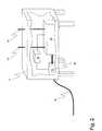
- FIG. 2 shows a partially cut mobile and elevated combustion plant 7 with a compressor 11 to compress sucked gas.
- the compressed gas or directly supplied liquid are finally fed to a burner unit 12, which in turn has a combustion air supply 13 and an exhaust gas outlet 14.
- the burner unit 12, or its ignition unit is in turn connected to a controller 15, via which, in the example shown, the energy supply of the ignition unit also takes place.
- the controller 11 controls the compressor 11 as well as other controllable components of the burner unit 12.
- the incinerator 7 may also be coupled to a control unit of the pumping / suction device 3.
Landscapes
- Engineering & Computer Science (AREA)
- Mechanical Engineering (AREA)
- General Engineering & Computer Science (AREA)
- Environmental & Geological Engineering (AREA)
- Treating Waste Gases (AREA)
- Filling Or Discharging Of Gas Storage Vessels (AREA)
Claims (15)
- Procédé d'élimination de liquides et/ou de gaz hors d'un dispositif (1) de stockage et/ou de transport de produits solides, liquides et/ou gazeux, en particulier d'un réservoir de stockage (2a, 2b) ou d'une tuyauterie, caractérisé en ce que ledit dispositif (1), un véhicule de pompage / d'aspiration mobile (4) et une installation d'incinération mobile (7) disposée séparément, sont connectés entre eux à l'aide de conduites (8a, 8b, 8c, 8d), et en ce qu'ensuite un liquide et/ou un gaz est transféré depuis le dispositif (1) à l'aide d'un équipement de pompage / d'aspiration (3) du véhicule de pompage / d'aspiration (4) dans un réservoir intermédiaire du véhicule de pompage / d'aspiration (4), par exemple sous forme d'une unité de réservoir (5), puis alimenté à l'installation d'incinération mobile (7).
- Procédé selon la revendication précédente, caractérisé en ce que l'équipement de pompage / d'aspiration (3) est accouplé entre le dispositif (1) et l'installation d'incinération (7) au début du procédé, et en ce que le liquide et/ou le gaz est aspiré hors du dispositif (1).
- Procédé selon la revendication 1, caractérisé en ce que le dispositif (1) est accouplé entre l'équipement de pompage / d'aspiration (3) et l'installation d'incinération (7) au début du procédé, et le liquide et/ou le gaz est expulsé hors dudit le dispositif (1) par la création d'une surpression.
- Procédé selon une ou plusieurs des revendications qui précèdent, caractérisé en ce qu'une séparation est effectuée dans le réservoir intermédiaire entre le gaz aspiré hors du dispositif (1) et le liquide aspiré hors du dispositif (1), par exemple à l'aide d'un cyclone (6), et en ce qu'une seule des deux phases, préférablement le gaz séparé, est envoyée à l'installation d'incinération (7).
- Procédé selon la revendication 4, caractérisé en ce que seul le gaz séparé est envoyé à l'installation d'incinération (7), dans lequel le gaz séparé est d'abord renvoyé depuis le réservoir intermédiaire dans le dispositif (1), puis envoyé depuis le dispositif (1) à l'installation d'incinération (7).
- Procédé selon une ou plusieurs des revendications qui précèdent, caractérisé en ce que l'équipement de pompage / d'aspiration (3) et/ou l'installation d'incinération (7) sont commandés sur la base de données de mesure provenant d'au moins un capteur de liquide et/ou un capteur de gaz.
- Procédé selon une ou plusieurs des revendications qui précèdent, caractérisé en ce que l'installation d'incinération (7) et/ou l'équipement de pompage / d'aspiration (3) sont commandés à l'aide d'une commande du véhicule de pompage / d'aspiration (4).
- Procédé selon une ou plusieurs des revendications qui précèdent, caractérisé en ce que l'installation d'incinération (7) est alimentée par de l'énergie du véhicule de pompage / d'aspiration (4).
- Procédé selon une ou plusieurs des revendications qui précèdent, caractérisé en ce que l'installation d'incinération (7) reçoit uniquement le liquide et/ou le gaz, et en ce que l'installation d'incinération (7) fonctionne en outre de manière autonome.
- Système d'élimination de liquides et/ou de gaz hors d'un dispositif (1) de stockage et/ou de transport de produits solides, liquides et/ou gazeux, en particulier d'un réservoir de stockage (2a, 2b) ou d'une tuyauterie, pour mettre en oeuvre le procédé selon l'une des revendications précédentes, caractérisé en ce que le système comprend un véhicule de pompage / d'aspiration (4) qui comporte un équipement de pompage / d'aspiration mobile (3) et une installation d'incinération mobile (7) disposée séparément, dans lequel le véhicule de pompage / d'aspiration (4) comporte un réservoir intermédiaire, par exemple sous forme d'une unité de réservoir (5), qui est connecté à l'installation d'incinération (7) et à l'équipement de pompage / d'aspiration (3), et dans lequel le dispositif (1), l'équipement de pompage / d'aspiration mobile (3) et l'installation d'incinération (7) peuvent être connectés entre eux à l'aide des conduites (8a, 8b, 8c, 8d).
- Système selon la revendication précédente, caractérisé en ce que l'installation d'incinération (7) comporte tous les éléments nécessaires à son fonctionnement, tels qu'une unité d'incinération (12), un compresseur (11), une source d'énergie, une unité d'allumage, des capteurs de gaz ou de liquide, et/ou des équipements de production, de façon à pouvoir fonctionner de manière autonome.
- Système selon une ou plusieurs des revendications 10 et 11, caractérisé en ce que l'installation d'incinération (7) est en connexion fonctionnelle avec une source d'énergie et/ou une commande du véhicule de pompage / d'aspiration (4).
- Système selon une ou plusieurs des revendications 10 à 12, caractérisé en ce que l'installation d'incinération (7) peut être agencée dans un conteneur.
- Système selon une ou plusieurs des revendications 10 à 13, caractérisé en ce que l'installation d'incinération (7) et le véhicule de pompage / d'aspiration (4) peuvent être connectés à une ligne d'alimentation électrique (9) et/ou à une ligne de données (10).
- Système selon une ou plusieurs des revendications 10 à 14, caractérisé en ce que l'installation d'incinération comporte également un équipement de pompage / d'aspiration (3).
Applications Claiming Priority (2)
| Application Number | Priority Date | Filing Date | Title |
|---|---|---|---|
| DE202009016441U DE202009016441U1 (de) | 2009-04-17 | 2009-04-17 | System zur Entfernung von Flüssigkeiten und/oder Gasen |
| DE102009002455A DE102009002455A1 (de) | 2009-04-17 | 2009-04-17 | Verfahren und System zur Entfernung von Flüssigkeiten und/oder Gasen |
Publications (4)
| Publication Number | Publication Date |
|---|---|
| EP2241806A2 EP2241806A2 (fr) | 2010-10-20 |
| EP2241806A9 EP2241806A9 (fr) | 2011-01-12 |
| EP2241806A3 EP2241806A3 (fr) | 2013-10-30 |
| EP2241806B1 true EP2241806B1 (fr) | 2015-04-08 |
Family
ID=42134401
Family Applications (1)
| Application Number | Title | Priority Date | Filing Date |
|---|---|---|---|
| EP20100152806 Active EP2241806B1 (fr) | 2009-04-17 | 2010-02-05 | Procédé et système d'élimination de liquides et/ou de gaz |
Country Status (3)
| Country | Link |
|---|---|
| EP (1) | EP2241806B1 (fr) |
| DE (2) | DE202009016441U1 (fr) |
| ES (1) | ES2539701T3 (fr) |
Cited By (2)
| Publication number | Priority date | Publication date | Assignee | Title |
|---|---|---|---|---|
| DE102021116269A1 (de) | 2021-06-23 | 2022-12-29 | Endegs Gmbh | System zur Entfernung von Flüssigkeiten und/oder Gasen sowie Verfahren zum Betreiben eines Systems |
| WO2022268687A1 (fr) | 2021-06-23 | 2022-12-29 | Endegs Gmbh | Système d'élimination de liquides et/ou de gaz et procédé de montage et d'actionnement de système |
Families Citing this family (4)
| Publication number | Priority date | Publication date | Assignee | Title |
|---|---|---|---|---|
| DE102010031419A1 (de) * | 2010-07-15 | 2012-01-19 | Endegs Gmbh | System und Verfahren zum Entgasen einer Lager- und/oder Transporteinrichtung für Feststoffe, Flüssigkeiten und/oder Gase |
| DE102011003972A1 (de) * | 2011-02-11 | 2012-08-16 | Endegs Gmbh | System und Verfahren zum Entgasen einer Lager- und/oder Transporteinrichtung für Feststoffe, Flüssigkeiten und/oder Gase |
| DE102013206908A1 (de) * | 2013-04-17 | 2014-10-23 | Dürr Systems GmbH | Verfahren und Vorrichtung zum Innenreinigen eines Fluidtanks |
| DE102013113814A1 (de) * | 2013-12-11 | 2015-06-11 | Endegs Gmbh | Brenneranordnung und Verfahren zum Betrieb derselben |
Family Cites Families (14)
| Publication number | Priority date | Publication date | Assignee | Title |
|---|---|---|---|---|
| CH486370A (de) * | 1967-12-18 | 1970-02-28 | Endress Ag Autogen | Einrichtung zum Entfernen brennbarer Gase aus Flüssigkeitsbehältern |
| US3817687A (en) * | 1973-07-18 | 1974-06-18 | Aer Corp | Hydrocarbon oxidizer system |
| DE3427719C2 (de) * | 1984-07-27 | 1986-08-14 | Horst P. Dr.-Ing. 8069 Gerolsbach Sauerwein | Verbrennungsofen für hochgiftige Abfälle |
| ATE46885T1 (de) * | 1985-03-04 | 1989-10-15 | Vincent G Grey | Verfahren und schiff fuer die verbrennung von gefaehrlichen abfallstoffen auf offener see. |
| US5325795A (en) * | 1990-02-05 | 1994-07-05 | Hrubetz Environmental Services, Inc. | Mobile material decontamination apparatus |
| US5377723A (en) * | 1993-09-03 | 1995-01-03 | Henry T. Hilliard, Jr. | Method and apparatus for venting a storage vessel |
| US6267931B1 (en) * | 1994-02-03 | 2001-07-31 | Earth Resources Corporation | Reconfigurable waste treatment system |
| US6176275B1 (en) * | 1999-02-03 | 2001-01-23 | Bob J. Hill | Vapor recovery system for mobile fuelers |
| DE10010163C2 (de) * | 2000-03-03 | 2002-02-28 | Ralf Laskowski | Verfahren zur Verwertung von kohlenwasserstoffhaltigen Altstoffen und Anlage zur Durchführung des Verfahrens |
| US6352040B1 (en) * | 2000-11-22 | 2002-03-05 | Randall P. Voorhees | Mobile armored incinerator |
| DE202004006411U1 (de) | 2004-04-20 | 2004-07-29 | Intherma Holding Gmbh & Co. Kg | Anlage zur Verbrennung von unerwünschten Gasen |
| US7677883B2 (en) * | 2006-04-04 | 2010-03-16 | Expro Americas, Llc | Trailer mounted smokeless dual-phase burner system |
| DE502006003324D1 (de) | 2006-06-22 | 2009-05-14 | Intherma Holding Gmbh & Co Kg | Anlage zur Verbrennung von unerwünschten Gasen |
| US7571687B2 (en) * | 2006-08-08 | 2009-08-11 | Cornellier J Rene | Apparatus for destruction of organic pollutants |
-
2009
- 2009-04-17 DE DE202009016441U patent/DE202009016441U1/de not_active Expired - Lifetime
- 2009-04-17 DE DE102009002455A patent/DE102009002455A1/de not_active Withdrawn
-
2010
- 2010-02-05 ES ES10152806.5T patent/ES2539701T3/es active Active
- 2010-02-05 EP EP20100152806 patent/EP2241806B1/fr active Active
Cited By (4)
| Publication number | Priority date | Publication date | Assignee | Title |
|---|---|---|---|---|
| DE102021116269A1 (de) | 2021-06-23 | 2022-12-29 | Endegs Gmbh | System zur Entfernung von Flüssigkeiten und/oder Gasen sowie Verfahren zum Betreiben eines Systems |
| WO2022268687A1 (fr) | 2021-06-23 | 2022-12-29 | Endegs Gmbh | Système d'élimination de liquides et/ou de gaz et procédé de montage et d'actionnement de système |
| WO2022268697A1 (fr) | 2021-06-23 | 2022-12-29 | Endegs Gmbh | Système d'élimination de liquides et/ou de gaz et procédé d'actionnement de système |
| DE102021116259A1 (de) | 2021-06-23 | 2022-12-29 | Endegs Gmbh | System zur Entfernung von Flüssigkeiten und/oder Gasen sowie Verfahren zum Aufstellen und zur Inbetriebnahme eines Systems |
Also Published As
| Publication number | Publication date |
|---|---|
| DE102009002455A1 (de) | 2010-10-21 |
| EP2241806A2 (fr) | 2010-10-20 |
| ES2539701T3 (es) | 2015-07-03 |
| EP2241806A3 (fr) | 2013-10-30 |
| EP2241806A9 (fr) | 2011-01-12 |
| DE202009016441U1 (de) | 2010-04-29 |
Similar Documents
| Publication | Publication Date | Title |
|---|---|---|
| EP2241806A9 (fr) | Procédé et système d'élimination de liquides et/ou de gaz | |
| EP2707644B1 (fr) | Purgeur de condensat pour système de gaz comprimé | |
| DE4323719C2 (de) | Verfahren und Einrichtung zur Durchführung des Verfahrens zur Wasserversorgung an Bord eines Flugzeuges | |
| DE102011117158B4 (de) | Tanksystem für ein Kraftfahrzeug sowie Betriebsverfahren hierfür | |
| DE4225170A1 (de) | Tankanlage und Verfahren zum Betrieb einer Tankanlage mit einem Tank zur Lagerung von brennbaren Flüssigkeiten | |
| DE112007001857B4 (de) | Dampfeinschlußkanister für ein Dampfdruck-Managementsystem | |
| EP3589381B1 (fr) | Procédé de dégazage de hydrogène d'un liquide porteur de hydrogène | |
| DE102011003972A1 (de) | System und Verfahren zum Entgasen einer Lager- und/oder Transporteinrichtung für Feststoffe, Flüssigkeiten und/oder Gase | |
| EP2700875B1 (fr) | Procédé pour le traitement thermique de matériaux de démolition routiers contenant du PAK ou de boues pétrolières | |
| US6935387B1 (en) | Odor control assembly | |
| DE102016223301B4 (de) | System zum Betreiben eines Fahrzeugs | |
| DE102017001039A1 (de) | Verfahren zum sicheren Betanken eines Gasspeichers | |
| EP2964478B1 (fr) | Contenant à carburant pourvu d'un séparateur de liquide pouvant être vidé de manière pneumatique | |
| EP2811229B1 (fr) | Installation transportable destinée à la combustion de gaz indésirables | |
| DE102010031419A1 (de) | System und Verfahren zum Entgasen einer Lager- und/oder Transporteinrichtung für Feststoffe, Flüssigkeiten und/oder Gase | |
| DE1782549C3 (de) | Einrichtung zur Entfernung von brennbaren Gasresten aus Flüssigkeitsbehältern | |
| DE102021116259A1 (de) | System zur Entfernung von Flüssigkeiten und/oder Gasen sowie Verfahren zum Aufstellen und zur Inbetriebnahme eines Systems | |
| DE102019202383A1 (de) | Verfahren zum Betreiben einer Antriebseinrichtung für ein Kraftfahrzeug sowie entsprechende Antriebseinrichtung | |
| DE202007019008U1 (de) | Abgastank, der ein Verfahren ermöglicht, die Speicherung (Lagerung) der Abgase von Verbrennungsmotoren in Betrieb-Während fahren bei Kraftfahrzeugen aller Art, mittels Hilfe eines Abgassammeltank der unter Druck im gasförmigen Zustand zur Speicherung (Lagerung) dient | |
| DE202008013957U1 (de) | Vorrichtung zur Rückgewinnung von Kraftstoff | |
| EP2792425B1 (fr) | Procédé, dispositif et utilisation d'un système de turbine pour le nettoyage intérieur d'un réservoir de fluide | |
| AT405171B (de) | Verfahren zum zumindest teilweisen entfernen von luft aus einem flüssiggastank und druckluft-luftpumpe auf der basis eines venturirohres zur verwendung bei einem solchen verfahren | |
| WO2022268697A1 (fr) | Système d'élimination de liquides et/ou de gaz et procédé d'actionnement de système | |
| DE102018215877A1 (de) | Abgaseinrichtung für eine Verbrennungskraftmaschine eines Kraftfahrzeugs und Kraftfahrzeug mit einer solchen Abgaseinrichtung | |
| DE4217904C1 (fr) |
Legal Events
| Date | Code | Title | Description |
|---|---|---|---|
| PUAI | Public reference made under article 153(3) epc to a published international application that has entered the european phase |
Free format text: ORIGINAL CODE: 0009012 |
|
| AK | Designated contracting states |
Kind code of ref document: A2 Designated state(s): AT BE BG CH CY CZ DE DK EE ES FI FR GB GR HR HU IE IS IT LI LT LU LV MC MK MT NL NO PL PT RO SE SI SK SM TR |
|
| PUAL | Search report despatched |
Free format text: ORIGINAL CODE: 0009013 |
|
| AK | Designated contracting states |
Kind code of ref document: A3 Designated state(s): AT BE BG CH CY CZ DE DK EE ES FI FR GB GR HR HU IE IS IT LI LT LU LV MC MK MT NL NO PL PT RO SE SI SK SM TR |
|
| RIC1 | Information provided on ipc code assigned before grant |
Ipc: B08B 9/08 20060101ALI20130926BHEP Ipc: F23G 7/06 20060101AFI20130926BHEP Ipc: F23G 5/40 20060101ALI20130926BHEP |
|
| 17P | Request for examination filed |
Effective date: 20140331 |
|
| RBV | Designated contracting states (corrected) |
Designated state(s): AT BE BG CH CY CZ DE DK EE ES FI FR GB GR HR HU IE IS IT LI LT LU LV MC MK MT NL NO PL PT RO SE SI SK SM TR |
|
| GRAP | Despatch of communication of intention to grant a patent |
Free format text: ORIGINAL CODE: EPIDOSNIGR1 |
|
| INTG | Intention to grant announced |
Effective date: 20141023 |
|
| GRAS | Grant fee paid |
Free format text: ORIGINAL CODE: EPIDOSNIGR3 |
|
| GRAA | (expected) grant |
Free format text: ORIGINAL CODE: 0009210 |
|
| AK | Designated contracting states |
Kind code of ref document: B1 Designated state(s): AT BE BG CH CY CZ DE DK EE ES FI FR GB GR HR HU IE IS IT LI LT LU LV MC MK MT NL NO PL PT RO SE SI SK SM TR |
|
| REG | Reference to a national code |
Ref country code: GB Ref legal event code: FG4D Free format text: NOT ENGLISH |
|
| REG | Reference to a national code |
Ref country code: CH Ref legal event code: EP |
|
| REG | Reference to a national code |
Ref country code: IE Ref legal event code: FG4D Free format text: LANGUAGE OF EP DOCUMENT: GERMAN |
|
| REG | Reference to a national code |
Ref country code: AT Ref legal event code: REF Ref document number: 720874 Country of ref document: AT Kind code of ref document: T Effective date: 20150515 |
|
| REG | Reference to a national code |
Ref country code: DE Ref legal event code: R096 Ref document number: 502010009275 Country of ref document: DE Effective date: 20150521 |
|
| REG | Reference to a national code |
Ref country code: ES Ref legal event code: FG2A Ref document number: 2539701 Country of ref document: ES Kind code of ref document: T3 Effective date: 20150703 |
|
| REG | Reference to a national code |
Ref country code: NL Ref legal event code: T3 |
|
| REG | Reference to a national code |
Ref country code: NO Ref legal event code: T2 Effective date: 20150408 |
|
| REG | Reference to a national code |
Ref country code: LT Ref legal event code: MG4D |
|
| PG25 | Lapsed in a contracting state [announced via postgrant information from national office to epo] |
Ref country code: PT Free format text: LAPSE BECAUSE OF FAILURE TO SUBMIT A TRANSLATION OF THE DESCRIPTION OR TO PAY THE FEE WITHIN THE PRESCRIBED TIME-LIMIT Effective date: 20150810 Ref country code: FI Free format text: LAPSE BECAUSE OF FAILURE TO SUBMIT A TRANSLATION OF THE DESCRIPTION OR TO PAY THE FEE WITHIN THE PRESCRIBED TIME-LIMIT Effective date: 20150408 Ref country code: HR Free format text: LAPSE BECAUSE OF FAILURE TO SUBMIT A TRANSLATION OF THE DESCRIPTION OR TO PAY THE FEE WITHIN THE PRESCRIBED TIME-LIMIT Effective date: 20150408 Ref country code: LT Free format text: LAPSE BECAUSE OF FAILURE TO SUBMIT A TRANSLATION OF THE DESCRIPTION OR TO PAY THE FEE WITHIN THE PRESCRIBED TIME-LIMIT Effective date: 20150408 |
|
| PG25 | Lapsed in a contracting state [announced via postgrant information from national office to epo] |
Ref country code: GR Free format text: LAPSE BECAUSE OF FAILURE TO SUBMIT A TRANSLATION OF THE DESCRIPTION OR TO PAY THE FEE WITHIN THE PRESCRIBED TIME-LIMIT Effective date: 20150709 Ref country code: LV Free format text: LAPSE BECAUSE OF FAILURE TO SUBMIT A TRANSLATION OF THE DESCRIPTION OR TO PAY THE FEE WITHIN THE PRESCRIBED TIME-LIMIT Effective date: 20150408 Ref country code: IS Free format text: LAPSE BECAUSE OF FAILURE TO SUBMIT A TRANSLATION OF THE DESCRIPTION OR TO PAY THE FEE WITHIN THE PRESCRIBED TIME-LIMIT Effective date: 20150808 |
|
| REG | Reference to a national code |
Ref country code: DE Ref legal event code: R097 Ref document number: 502010009275 Country of ref document: DE |
|
| PG25 | Lapsed in a contracting state [announced via postgrant information from national office to epo] |
Ref country code: EE Free format text: LAPSE BECAUSE OF FAILURE TO SUBMIT A TRANSLATION OF THE DESCRIPTION OR TO PAY THE FEE WITHIN THE PRESCRIBED TIME-LIMIT Effective date: 20150408 Ref country code: DK Free format text: LAPSE BECAUSE OF FAILURE TO SUBMIT A TRANSLATION OF THE DESCRIPTION OR TO PAY THE FEE WITHIN THE PRESCRIBED TIME-LIMIT Effective date: 20150408 |
|
| PLBE | No opposition filed within time limit |
Free format text: ORIGINAL CODE: 0009261 |
|
| STAA | Information on the status of an ep patent application or granted ep patent |
Free format text: STATUS: NO OPPOSITION FILED WITHIN TIME LIMIT |
|
| REG | Reference to a national code |
Ref country code: FR Ref legal event code: PLFP Year of fee payment: 7 |
|
| PG25 | Lapsed in a contracting state [announced via postgrant information from national office to epo] |
Ref country code: CZ Free format text: LAPSE BECAUSE OF FAILURE TO SUBMIT A TRANSLATION OF THE DESCRIPTION OR TO PAY THE FEE WITHIN THE PRESCRIBED TIME-LIMIT Effective date: 20150408 Ref country code: PL Free format text: LAPSE BECAUSE OF FAILURE TO SUBMIT A TRANSLATION OF THE DESCRIPTION OR TO PAY THE FEE WITHIN THE PRESCRIBED TIME-LIMIT Effective date: 20150408 Ref country code: RO Free format text: LAPSE BECAUSE OF NON-PAYMENT OF DUE FEES Effective date: 20150408 Ref country code: SK Free format text: LAPSE BECAUSE OF FAILURE TO SUBMIT A TRANSLATION OF THE DESCRIPTION OR TO PAY THE FEE WITHIN THE PRESCRIBED TIME-LIMIT Effective date: 20150408 |
|
| 26N | No opposition filed |
Effective date: 20160111 |
|
| PG25 | Lapsed in a contracting state [announced via postgrant information from national office to epo] |
Ref country code: SI Free format text: LAPSE BECAUSE OF FAILURE TO SUBMIT A TRANSLATION OF THE DESCRIPTION OR TO PAY THE FEE WITHIN THE PRESCRIBED TIME-LIMIT Effective date: 20150408 |
|
| PG25 | Lapsed in a contracting state [announced via postgrant information from national office to epo] |
Ref country code: MC Free format text: LAPSE BECAUSE OF FAILURE TO SUBMIT A TRANSLATION OF THE DESCRIPTION OR TO PAY THE FEE WITHIN THE PRESCRIBED TIME-LIMIT Effective date: 20150408 |
|
| REG | Reference to a national code |
Ref country code: IE Ref legal event code: MM4A |
|
| PG25 | Lapsed in a contracting state [announced via postgrant information from national office to epo] |
Ref country code: IE Free format text: LAPSE BECAUSE OF NON-PAYMENT OF DUE FEES Effective date: 20160205 |
|
| REG | Reference to a national code |
Ref country code: FR Ref legal event code: PLFP Year of fee payment: 8 |
|
| PG25 | Lapsed in a contracting state [announced via postgrant information from national office to epo] |
Ref country code: SE Free format text: LAPSE BECAUSE OF FAILURE TO SUBMIT A TRANSLATION OF THE DESCRIPTION OR TO PAY THE FEE WITHIN THE PRESCRIBED TIME-LIMIT Effective date: 20150408 |
|
| PG25 | Lapsed in a contracting state [announced via postgrant information from national office to epo] |
Ref country code: MT Free format text: LAPSE BECAUSE OF FAILURE TO SUBMIT A TRANSLATION OF THE DESCRIPTION OR TO PAY THE FEE WITHIN THE PRESCRIBED TIME-LIMIT Effective date: 20150408 |
|
| REG | Reference to a national code |
Ref country code: FR Ref legal event code: PLFP Year of fee payment: 9 |
|
| PGFP | Annual fee paid to national office [announced via postgrant information from national office to epo] |
Ref country code: LU Payment date: 20180222 Year of fee payment: 9 |
|
| PGFP | Annual fee paid to national office [announced via postgrant information from national office to epo] |
Ref country code: GB Payment date: 20180226 Year of fee payment: 9 |
|
| PG25 | Lapsed in a contracting state [announced via postgrant information from national office to epo] |
Ref country code: CY Free format text: LAPSE BECAUSE OF FAILURE TO SUBMIT A TRANSLATION OF THE DESCRIPTION OR TO PAY THE FEE WITHIN THE PRESCRIBED TIME-LIMIT Effective date: 20150408 Ref country code: HU Free format text: LAPSE BECAUSE OF FAILURE TO SUBMIT A TRANSLATION OF THE DESCRIPTION OR TO PAY THE FEE WITHIN THE PRESCRIBED TIME-LIMIT; INVALID AB INITIO Effective date: 20100205 Ref country code: SM Free format text: LAPSE BECAUSE OF FAILURE TO SUBMIT A TRANSLATION OF THE DESCRIPTION OR TO PAY THE FEE WITHIN THE PRESCRIBED TIME-LIMIT Effective date: 20150408 |
|
| PGFP | Annual fee paid to national office [announced via postgrant information from national office to epo] |
Ref country code: TR Payment date: 20180201 Year of fee payment: 9 |
|
| PG25 | Lapsed in a contracting state [announced via postgrant information from national office to epo] |
Ref country code: MK Free format text: LAPSE BECAUSE OF FAILURE TO SUBMIT A TRANSLATION OF THE DESCRIPTION OR TO PAY THE FEE WITHIN THE PRESCRIBED TIME-LIMIT Effective date: 20150408 |
|
| PG25 | Lapsed in a contracting state [announced via postgrant information from national office to epo] |
Ref country code: BG Free format text: LAPSE BECAUSE OF FAILURE TO SUBMIT A TRANSLATION OF THE DESCRIPTION OR TO PAY THE FEE WITHIN THE PRESCRIBED TIME-LIMIT Effective date: 20150408 |
|
| GBPC | Gb: european patent ceased through non-payment of renewal fee |
Effective date: 20190205 |
|
| PG25 | Lapsed in a contracting state [announced via postgrant information from national office to epo] |
Ref country code: LU Free format text: LAPSE BECAUSE OF NON-PAYMENT OF DUE FEES Effective date: 20190205 |
|
| PG25 | Lapsed in a contracting state [announced via postgrant information from national office to epo] |
Ref country code: GB Free format text: LAPSE BECAUSE OF NON-PAYMENT OF DUE FEES Effective date: 20190205 |
|
| PG25 | Lapsed in a contracting state [announced via postgrant information from national office to epo] |
Ref country code: TR Free format text: LAPSE BECAUSE OF NON-PAYMENT OF DUE FEES Effective date: 20190205 |
|
| REG | Reference to a national code |
Ref country code: NL Ref legal event code: PD Owner name: SIS GMBH; DE Free format text: DETAILS ASSIGNMENT: CHANGE OF OWNER(S), MERGE; FORMER OWNER NAME: ENDEGS GMBH Effective date: 20250203 Ref country code: NL Ref legal event code: HC Owner name: ETS DEGASSING GMBH; DE Free format text: DETAILS ASSIGNMENT: CHANGE OF OWNER(S), CHANGE OF OWNER(S) NAME; FORMER OWNER NAME: SIS GMBH Effective date: 20250203 |
|
| REG | Reference to a national code |
Ref country code: DE Ref legal event code: R081 Ref document number: 502010009275 Country of ref document: DE Owner name: ETS DEGASSING GMBH, DE Free format text: FORMER OWNER: ENDEGS GMBH, 85055 INGOLSTADT, DE |
|
| REG | Reference to a national code |
Ref country code: AT Ref legal event code: PC Ref document number: 720874 Country of ref document: AT Kind code of ref document: T Owner name: ETS DEGASSING GMBH, DE Effective date: 20250310 |
|
| REG | Reference to a national code |
Ref country code: BE Ref legal event code: PD Owner name: ETS DEGASSING GMBH; DE Free format text: DETAILS ASSIGNMENT: CHANGE OF OWNER(S), MERGE; FORMER OWNER NAME: KIRKPATRICK Effective date: 20250218 |
|
| REG | Reference to a national code |
Ref country code: CH Ref legal event code: U11 Free format text: ST27 STATUS EVENT CODE: U-0-0-U10-U11 (AS PROVIDED BY THE NATIONAL OFFICE) Effective date: 20260301 |
|
| PGFP | Annual fee paid to national office [announced via postgrant information from national office to epo] |
Ref country code: NL Payment date: 20260228 Year of fee payment: 17 |
|
| PGFP | Annual fee paid to national office [announced via postgrant information from national office to epo] |
Ref country code: ES Payment date: 20260302 Year of fee payment: 17 |
|
| PGFP | Annual fee paid to national office [announced via postgrant information from national office to epo] |
Ref country code: NO Payment date: 20260226 Year of fee payment: 17 Ref country code: DE Payment date: 20260130 Year of fee payment: 17 |
|
| PGFP | Annual fee paid to national office [announced via postgrant information from national office to epo] |
Ref country code: AT Payment date: 20260223 Year of fee payment: 17 |
|
| PGFP | Annual fee paid to national office [announced via postgrant information from national office to epo] |
Ref country code: BE Payment date: 20260225 Year of fee payment: 17 Ref country code: IT Payment date: 20260227 Year of fee payment: 17 |
|
| PGFP | Annual fee paid to national office [announced via postgrant information from national office to epo] |
Ref country code: FR Payment date: 20260225 Year of fee payment: 17 |
|
| PGFP | Annual fee paid to national office [announced via postgrant information from national office to epo] |
Ref country code: CH Payment date: 20260301 Year of fee payment: 17 |