EP2241799B1 - Anzeigeanordnung mit Lichtröhre mit zentralem Raum für Lichtquelle - Google Patents
Anzeigeanordnung mit Lichtröhre mit zentralem Raum für Lichtquelle Download PDFInfo
- Publication number
- EP2241799B1 EP2241799B1 EP10159402.6A EP10159402A EP2241799B1 EP 2241799 B1 EP2241799 B1 EP 2241799B1 EP 10159402 A EP10159402 A EP 10159402A EP 2241799 B1 EP2241799 B1 EP 2241799B1
- Authority
- EP
- European Patent Office
- Prior art keywords
- light
- channel segment
- front face
- pipe
- display assembly
- Prior art date
- Legal status (The legal status is an assumption and is not a legal conclusion. Google has not performed a legal analysis and makes no representation as to the accuracy of the status listed.)
- Active
Links
Images


Classifications
-
- G—PHYSICS
- G02—OPTICS
- G02B—OPTICAL ELEMENTS, SYSTEMS OR APPARATUS
- G02B6/00—Light guides; Structural details of arrangements comprising light guides and other optical elements, e.g. couplings
- G02B6/0001—Light guides; Structural details of arrangements comprising light guides and other optical elements, e.g. couplings specially adapted for lighting devices or systems
- G02B6/0011—Light guides; Structural details of arrangements comprising light guides and other optical elements, e.g. couplings specially adapted for lighting devices or systems the light guides being planar or of plate-like form
- G02B6/0013—Means for improving the coupling-in of light from the light source into the light guide
- G02B6/0015—Means for improving the coupling-in of light from the light source into the light guide provided on the surface of the light guide or in the bulk of it
- G02B6/002—Means for improving the coupling-in of light from the light source into the light guide provided on the surface of the light guide or in the bulk of it by shaping at least a portion of the light guide, e.g. with collimating, focussing or diverging surfaces
- G02B6/0021—Means for improving the coupling-in of light from the light source into the light guide provided on the surface of the light guide or in the bulk of it by shaping at least a portion of the light guide, e.g. with collimating, focussing or diverging surfaces for housing at least a part of the light source, e.g. by forming holes or recesses
-
- G—PHYSICS
- G02—OPTICS
- G02B—OPTICAL ELEMENTS, SYSTEMS OR APPARATUS
- G02B6/00—Light guides; Structural details of arrangements comprising light guides and other optical elements, e.g. couplings
- G02B6/0001—Light guides; Structural details of arrangements comprising light guides and other optical elements, e.g. couplings specially adapted for lighting devices or systems
- G02B6/0011—Light guides; Structural details of arrangements comprising light guides and other optical elements, e.g. couplings specially adapted for lighting devices or systems the light guides being planar or of plate-like form
- G02B6/0033—Means for improving the coupling-out of light from the light guide
- G02B6/0035—Means for improving the coupling-out of light from the light guide provided on the surface of the light guide or in the bulk of it
-
- G—PHYSICS
- G02—OPTICS
- G02B—OPTICAL ELEMENTS, SYSTEMS OR APPARATUS
- G02B6/00—Light guides; Structural details of arrangements comprising light guides and other optical elements, e.g. couplings
- G02B6/0001—Light guides; Structural details of arrangements comprising light guides and other optical elements, e.g. couplings specially adapted for lighting devices or systems
- G02B6/0011—Light guides; Structural details of arrangements comprising light guides and other optical elements, e.g. couplings specially adapted for lighting devices or systems the light guides being planar or of plate-like form
- G02B6/0013—Means for improving the coupling-in of light from the light source into the light guide
- G02B6/0023—Means for improving the coupling-in of light from the light source into the light guide provided by one optical element, or plurality thereof, placed between the light guide and the light source, or around the light source
- G02B6/0031—Reflecting element, sheet or layer
-
- G—PHYSICS
- G02—OPTICS
- G02B—OPTICAL ELEMENTS, SYSTEMS OR APPARATUS
- G02B6/00—Light guides; Structural details of arrangements comprising light guides and other optical elements, e.g. couplings
- G02B6/0001—Light guides; Structural details of arrangements comprising light guides and other optical elements, e.g. couplings specially adapted for lighting devices or systems
- G02B6/0011—Light guides; Structural details of arrangements comprising light guides and other optical elements, e.g. couplings specially adapted for lighting devices or systems the light guides being planar or of plate-like form
- G02B6/0033—Means for improving the coupling-out of light from the light guide
- G02B6/0035—Means for improving the coupling-out of light from the light guide provided on the surface of the light guide or in the bulk of it
- G02B6/0036—2-D arrangement of prisms, protrusions, indentations or roughened surfaces
Definitions
- This invention relates to a display assembly comprising a light pipe to illuminate a display. More particularly, this invention relates to such assembly that comprises a light pipe defining a compartment for receiving a light source and light-extracting channel segments symmetrical about the compartment to provide improved illumination of the display.
- a display assembly comprising a display device, such as a liquid crystal device, illuminated by light emitted by a light pipe.
- a light source such as an LED
- a light source is located proximate an edge of the light pipe. Light from the light source enters the light pipe through the edge and is extracted through the front face toward the display device.
- the light intensity needs to be sufficient to provide suitable light to remote areas of the display.
- a significant portion of the light from the light source is emitted in directions away from the light pipe, and either needs to be reflected back toward the light pipe or is lost for purposes of illuminating the display.
- Document US2008/266878A1 relates to an optical plate for use in, for example, a backlight module.
- Document EP1959277A1 relates to a light mixer and a backlight module having the light mixer.
- US2008/225522A1 relates to a surface light source device and a LCD unit including the same.
- Document US2007/086179 relates to a light mixing plate and a backlight module utilizing the light mixing plate.
- an improved display assembly that includes a light pipe for illuminating the display, wherein the light source is located relative to the light pipe in a manner that allows a greater proportion of the light from the light source to enter the light pipe and increased illumination of the display, and further provides more symmetrically uniform illumination of the display.
- a display assembly is provided according to claim 1 and adapted for emitting light to illuminate a display.
- the display assembly includes a light pipe having a front face and a rear face opposite the front face.
- the light pipe defines a compartment for receiving a light source.
- the light pipe also includes channel segments that are formed in the rear face and are symmetrical about the compartment.
- the channel segments have an outer wall and an inner wall effective to redirect light from the compartment toward the front face.
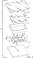
- a display assembly 10 comprises a light pipe 12 for emitting light to illuminate a display device 14 overlying pipe 12.
- a suitable display device is a liquid crystal display (LCD) device.
- this invention may be used to illuminate any display device that requires backlighting to present visual information.
- Assembly 10 further comprises a diffuser 26 overlying pipe 12 and intermediate pipe 12 and display 14.
- the diffuser is used to spread out and scatter light emitted from the light pipe across the display.
- a preferred diffuser is formed of a white polymeric film, such as white polycarbonate film.
- assembly 10 includes a brightness enhancing film 28 intermediate device 14 and diffuser 26 that further increases the luminance.
- Pipe 12 is formed of a transparent material. Suitable materials include glass and polymeric resin such as an acrylic or polycarbonate compound. Pipe 12 includes a front face 16 and a rear face 18 opposite front face 16 that are planar and parallel, and sides 19 intermediate faces 16, 18. In this example, pipe 12 is rectangular. Pipe 12 defines a compartment 20 having an opening at rear face 18. Compartment 20 is defined by a cylindrical wall 21 that is optically smooth. As used herein, an optically smooth surface refers to a surface that is highly polished to minimize scattering of light impinging thereon. Alternately, the surfaces may be textured to increase scattering. Compartment 20 has a diameter and height sufficient to accommodate and receive a light source, which in the embodiment is a light emitting diode 48.
- a light source which in the embodiment is a light emitting diode 48.
- Assembly 10 also comprises a light shield 22 overlying compartment 20 to intercept light from diode 48 that is emitted directly toward the display device.
- shield 22 is adhesively bonded to front face 16 by an adhesive 23.
- a suitable adhesive is a transparent, ultraviolet curable acrylic adhesive.
- Shield 22 includes a reflective surface facing diode 48 that reflects the remainder of the light toward the light pipe.
- Adhesive 23 preferably bonds to face 16 with optical wetting to allow the reflected light to be admitted into the light pipe with minimal loss.
- shield 22 is formed of polymeric material and is semi-opaque to reflect the major portion of the light, while allowing some light to be transmitted therethrough for illuminating the center of the display. Alternately, shield 22 may be substantially opaque to minimize light transmission toward the center of the display.
- Shield 22 is suitable to be large enough to overlie the diode such that the diode is not seen by viewer looking into front face 16 of pipe 12 at any viewing angle.
- Assembly 10 also includes a housing 24 that surrounds pipe 12 and is spaced apart from sides 19.
- Housing 24 includes an inner surface 25 proximate to pipe 12 that is white and reflective.
- light pipe 12 includes a first channel segment 30 and a second channel segment 32 formed in rear face 18 and symmetrical about compartment 20.
- Pipe 12 also includes a third channel segment 34 and a fourth channel segment 36, also formed in rear face 18 and symmetrical about compartment 20.
- channel segments 30, 32, 34, 36 are linear and are interconnected to form a continuous, rectangular channel.
- Channel segments 30, 32, 34, 36 have an optically smooth surface.
- channel segments 30, 32, 34, 36 have a predetermined width W and a predetermined depth Y. In this embodiment, depth Y is about one-third of pipe thickness t.
- the amount of light intercepted by channel segment is proportional to the depth, so that a depth of one-third of the pipe thickness intercepts approximately one-third of the light traversing in pipe 12.
- the width W and the depth Y are selected based upon the desired uniformity and brightness requirements for backlighting display 14.
- Each channel segment 30, 32, 34, 36 includes an inner wall, an outer wall facing the inner wall and an end wall.
- channel segment 30 has inner wall 38 facing away from compartment 20, an outer wall 40 facing compartment 20, and an end wall 42.
- Inner wall 38 and outer wall 40 are planar and parallel, and are perpendicular to, and spaced apart from, front face 16.
- End wall 42 is planar and is in parallel, spaced relationship to front face 16.
- Diode 48 is preferably a thin, high flux device capable of producing high light illumination intensities. Diode 48 is mechanically and electrically attached to a circuit board 54 having connections for supplying electrical energy the diode. Pipe 12 is secured to circuit board 54 using mechanical fasteners (not shown). Circuit board 54 is typically formed of FR4 circuit board material, or the like. The surface of circuit board 54 proximate rear face 18 preferably comprises a reflective coating to increase the proportion and uniformity of light illuminating the display. Pipe 12 comprises stand-off feet 57 that prevents rear face 18 from resting directly on board 54 and defines an air space intermediate light pipe 12 and board 54, thereby providing an air interface at rear face 18.
- pipe 12 is formed of a transparent material having an index of refraction effective to internally reflect light propagating longitudinally therethrough.
- index of refraction of the material for light propagating through the light pipe at incident angles relative to the surfaces within a predetermined range, total internal reflection may be achieved when the index of refraction of the material is greater than the index of refraction of the adjacent material, typically air.
- Incident light outside the range is extracted through the front face and may be utilized for purposes of illuminating the display.
- channel segments are provided that alter the path of light rays so that the incident angel is outside the range, and thus extract the light.
- glow region refers to a region having relatively high luminance
- dark regions refer to regions having reduced luminance.
- central dark region 61 is created by shield 22 that reflects light from the light emitting diode, as indicted by ray L1, wherein light reflected by the shield propagates through the light pipe and, because it is not within the range of incident angles that result in internal reflection, is reflected by circuit board and extracted, thereby resulting in glow region 62 immediately about shield 22. Since in this embodiment, shield 22 is semi-opaque, region 61, although darker than the surrounding glow region 62, is illuminated by light that is transmitted through the shield, and so is not devoid of light.
- a substantial portion of light from diode 48 propagates within the light pipe at an angle that is internally reflected by the faces thereof, as indicated by rays L2 and L3. In this manner, the internally reflected light propagates through the light pipe until encountering a surface that redirects the light so as to allow the light to be exit the light pipe. Because the light is internally reflected, minimal light is emitted by dark regions 64 and 68. However, a portion of the light is intercepted by channel segments 30, 32, 34 and 36 and is redirected, as indicated by ray L2, at an angle that causes the light to be extracted, thereby resulting in glow region 66 and providing preferential backlighting for the middle region of display device 14.
- Light refracted by the channel segments may also be refracted toward circuit board 54 and reflected or scattered toward the front face, further contributing to glow region 66.
- a portion of the light propagating through the light pipe is not intercepted by the channel segments, for example, propagating within the light pipe between the front face and the end wall 42, as indicated by ray L3.
- the light Upon reaching sides 19, the light exits the light pipe and is reflected by housing 24 or circuit board 54, thereby resulting in glow region 70.
- Some light may be reflected back towards sides 19, reenters pipe 12, and propagates through the light pipe by internal reflection until being redirected by channel segments 30, 32, 34 and 36, or by compartment 20.
- illumination uniformity and intensity of display 10 is a function of the combination of light from glow regions 62, 66, and 70. Following extraction, the light is diffused by diffuser 26 to provide more uniform illumination of display device 14. Diffuser 26 combines and spreads out light emitted from the glow regions to provide illumination of the display, including in regions overlying dark regions 61, 64 and 68. Additionally, diffuser 26 assists to obscure the contents of display assembly 10 from the viewer of display 14. Brightness enhancing film 28 contains a series of parallel prisms (not shown) that allows light to exit substantially perpendicular to display 14, thus, redirecting remaining light back into pipe 12 within housing 24. The recycling of light in assembly 10 aids to produce uniform backlighting for display 14.
- backlighting is provided by light pipe having a rectangular channel with linear segments symmetrical about a central compartment.
- backlighting may be provided using channel segments that are arcuate, or channel segments that are not interconnected.
- a light pipe 112 comprises a first channel segment 130 that is arcuate, a second channel segment 132 that is arcuate, a third channel segment 134 that is arcuate, and a fourth channel segment 136 that is arcuate.
- Channel segments 130, 132, 134, 136 are in rear face 118.
- First channel segment 130 and second channel segment 132 are symmetrical about a compartment 120.
- Third channel segment 134 and fourth channel segment 136 are symmetrical about compartment 120.
- Third channel segment 134 is remote from compartment 120 and first channel segment 130.
- Fourth channel segment 136 is remote from compartment 120 and second channel segment 132.
- a first vertical channel segment 137, a second vertical channel segment 139, a first horizontal channel segment 141, and a second horizontal channel segment 143 are linear.
- Vertical channel segments 137, 139 are symmetrical about compartment 120.
- First vertical channel segment 137 is parallel to second vertical channel segment 139.
- Horizontal channel segments 141, 143 are symmetrical about compartment 120.
- First horizontal channel segment 141 is parallel to second horizontal channel segment 143.
- Vertical channel segments 137, 139 are perpendicular to horizontal channel segments 141, 143.
- the light shield is adhesively affixed to the front face of the light pipe.
- the light shield may be suitably disposed in a recess formed in the front face about the central compartment.
- a recess 276 is formed in the front face of pipe 212 about compartment 220 that contains diode 248.
- a light shield 222 is disposed in the recess.
- the light shield may be secured by adhesive.
- the light shield may be secured with a press, or interference fit securing to eliminate the need for adhesive.
- the light shield may be integrally molded (not shown) in the compartment of the light pipe.
- Recessing the light shield provides a front face for the light pipe that is planar, thereby allowing the overall height of the assembly to be reduced. Moreover, when a semi-opaque shield is used, positioning the shield closer to the light source may increase the portion of light transmitted therethrough to brighten illumination of the center of the display.
- the channel segments included an end wall that is planar and parallel to the front face of the light pipe.
- the channel segments include a concave end wall 142 intermediate the inner wall and the outer wall. The concave end wall facilitates manufacturing optically smooth channel surfaces that minimize light scattering.
- this invention provides a display assembly that provides improved backlight uniformity while achieving increased illumination levels.
- a light shield is provided overlying the compartment containing the light source to avoid an bright spot in the display.
- Channel segments in a rear face symmetrical about a compartment enhance illumination in the middle portion of the display.
- Light reflection about the sides of the light pipe provides enhanced illumination along an outer periphery of the display. This allows the light to be combined or spread out, for example, using a diffuser and a light enhancing film, to provide a desired illumination pattern for the display.
Landscapes
- Physics & Mathematics (AREA)
- General Physics & Mathematics (AREA)
- Optics & Photonics (AREA)
- Planar Illumination Modules (AREA)
Claims (13)
- Anzeigeanordnung (10), umfassend:einen Lichtleiter (12), der angepasst ist, um Licht zur Beleuchtung einer Anzeige (14) zu emittieren, wobei der Lichtleiter eine Vorderseite (16) und eine Rückseite (18) entgegengesetzt zu der Vorderseite umfasst, wobei der Lichtleiter ein Abteil (20) und ein erstes Kanalsegment (30) und ein zweites Kanalsegment (32) definiert, die relativ zu dem Abteil symmetrisch sind, wobei das erste Kanalsegment und das zweite Kanalsegment in der Rückseite ausgebildet sind und eine Außenwand (40) sowie eine Innenwand (38) aufweisen, die wirksam sind, um Licht von dem Abteil zu der Vorderseite hin umzulenken; undeine in das Abteil aufgenommene Lichtquelle (48), um Licht in den Lichtleiter einzulassen; undein Gehäuse (24), das den Lichtleiter (12) umgibt und von Seiten (19) des Lichtleiters (12) beabstandet ist, wobei die Innenfläche (25) des Gehäuses (24), die sich benachbart zu dem Lichtleiter (12) befindet, reflektierend ist;wobei Licht, das in den Lichtleiter (12) eigelassen wurde, in Kombination mit Licht, das von der reflektierenden Oberfläche (25) reflektiert wird, durch den Lichtleiter (12) aus der Vorderseite (16) emittiert wird, um die Anzeige (14) zu beleuchten;eine Lichtabschirmung (22, 222) die über dem Abteil (20) liegt und wirksam ist, um eine Emission von Licht aus dem Abteil (20) rechtwinklig zu der Vorderseite (16) zu verhindern;dadurch gekennzeichnet, dassdie Lichtabschirmung (22, 222) mit Klebstoff (23) an der Vorderseite (16) befestigt ist.
- Anzeigeanordnung (10) nach Anspruch 1, wobei der Klebstoff (23) transparent ist und eine Schicht zwischen der Vorderseite (16) und der Lichtabschirmung (22) ausbildet.
- Anzeigeanordnung (10) nach Anspruch 1, wobei der Lichtleiter (12) eine in der Vorderseite (16) ausgebildete Ausnehmung (276) umfasst, die über dem Abteil (20) liegt, und wobei die Lichtabdeckung (222) in der Ausnehmung (276) aufgenommen ist.
- Anzeigeanordnung (10) nach einem der Ansprüche 1 bis 3, die ferner eine Anzeige (14) umfasst, die über der Vorderseite (16) liegt und durch Licht beleuchtet werden kann, das aus der Vorderseite (16) emittiert wird.
- Anzeigeanordnung (10) nach einem der Ansprüche 1 bis 4, wobei jedes der Kanalsegmente (30, 32) eine Endwand (42) beinhaltet, die eben ist und sich in einer parallelen beabstandeten Beziehung zu der Vorderseite (16) befindet.
- Anzeigeanordnung (10) nach einem der Ansprüche 1 bis 5, wobei das erste Kanalsegment (30) und das zweite Kanalsegment (32) linear und parallel sind und wobei der Lichtleiter (12) ferner ein drittes Kanalsegment (34) und ein viertes Kanalsegment (36) umfasst, wobei das dritte Kanalsegment (34) und das vierte Kanalsegment (36) linear und parallel sind und wobei das erste Kanalsegment (30), das zweite Kanalsegment (32), das dritte Kanalsegment (34) und das vierte Kanalsegment (36) miteinander verbunden sind, um ein kontinuierliches rechteckiges Kanalsegment auszubilden.
- Anzeigeanordnung (10) nach einem der Ansprüche 1 bis 6, wobei der Lichtleiter (12) einen Rand aufweist und jedes der Kanalsegmente (30-36) sich zwischen dem Abteil (20) und dem Rand befindet.
- Anzeigeanordnung (10) nach einem der Ansprüche 1-5, wobei das erste Kanalsegment (30) und das zweite Kanalsegment (32) gebogen sind.
- Anzeigeanordnung (10) nach einem der Ansprüche 1 bis 8, wobei das Abteil (20) durch eine zylindrische Wand definiert ist.
- Anzeigeanordnung (10) nach einem der Ansprüche 1 bis 9, die ferner einen Streukörper (26) umfasst, der über der Vorderseite (16) liegt.
- Anzeigeanordnung (10) nach einem der Ansprüche 1 bis 10, die ferner einen Helligkeitsverbesserungsfilm (28) umfasst, der über dem Streukörper (26) entgegengesetzt zu dem Lichtleiter (12) liegt.
- Anzeigeanordnung (10) nach einem der Ansprüche 1 bis 11, wobei die Vorderseite (16) und die Rückseite (18) eben sind.
- Anzeigeanordnung (10) nach einem der Ansprüche 1 bis 4, wobei jedes der Kanalsegmente (30-36) zwischen der Innenwand (38) und der Außenwand (40) eine konkave Endwand (142) beinhaltet.
Applications Claiming Priority (1)
| Application Number | Priority Date | Filing Date | Title |
|---|---|---|---|
| US12/423,937 US8092061B2 (en) | 2009-04-15 | 2009-04-15 | Pipe having light-redirecting channels |
Publications (2)
| Publication Number | Publication Date |
|---|---|
| EP2241799A1 EP2241799A1 (de) | 2010-10-20 |
| EP2241799B1 true EP2241799B1 (de) | 2019-11-20 |
Family
ID=42245991
Family Applications (1)
| Application Number | Title | Priority Date | Filing Date |
|---|---|---|---|
| EP10159402.6A Active EP2241799B1 (de) | 2009-04-15 | 2010-04-08 | Anzeigeanordnung mit Lichtröhre mit zentralem Raum für Lichtquelle |
Country Status (2)
| Country | Link |
|---|---|
| US (1) | US8092061B2 (de) |
| EP (1) | EP2241799B1 (de) |
Families Citing this family (5)
| Publication number | Priority date | Publication date | Assignee | Title |
|---|---|---|---|---|
| WO2011004320A1 (en) * | 2009-07-09 | 2011-01-13 | Koninklijke Philips Electronics N.V. | Free form lighting module |
| US9632227B2 (en) | 2011-05-20 | 2017-04-25 | Yamaha Corporation | Light guide body |
| EP3084963B1 (de) | 2013-12-17 | 2019-05-15 | Electrolux Appliances Aktiebolag | Benutzerschnittstellenanordnung |
| US20180052272A1 (en) * | 2015-03-17 | 2018-02-22 | Philips Lighting Holding B.V. | Light spreading in textiles |
| JP6912748B1 (ja) * | 2020-02-07 | 2021-08-04 | 日亜化学工業株式会社 | 発光モジュール及び面状光源 |
Citations (1)
| Publication number | Priority date | Publication date | Assignee | Title |
|---|---|---|---|---|
| US20070086179A1 (en) * | 2005-10-14 | 2007-04-19 | Radiant Opto-Electronics Corporation | Light mixing plate and direct backlight module |
Family Cites Families (17)
| Publication number | Priority date | Publication date | Assignee | Title |
|---|---|---|---|---|
| US5397867A (en) | 1992-09-04 | 1995-03-14 | Lucas Industries, Inc. | Light distribution for illuminated keyboard switches and displays |
| JP2001305535A (ja) | 2000-04-18 | 2001-10-31 | Miyota Kk | 直下型バックライト |
| JP4023079B2 (ja) * | 2000-08-31 | 2007-12-19 | 株式会社日立製作所 | 面状照明装置及びこれを備えた表示装置 |
| DE10102586A1 (de) * | 2001-01-20 | 2002-07-25 | Philips Corp Intellectual Pty | Beleuchtungseinrichtung mit punktförmigen Lichtquellen |
| JP4438441B2 (ja) * | 2004-02-16 | 2010-03-24 | 日本電気株式会社 | 照明装置及びそれを備える表示装置 |
| US8297801B2 (en) * | 2004-07-16 | 2012-10-30 | Osram Sylvania Inc. | Light emitting diode disc optic with heat sink housing |
| KR100616598B1 (ko) * | 2004-08-11 | 2006-08-28 | 삼성전기주식회사 | 발광 다이오드 렌즈 및 이를 구비한 백라이트 모듈 |
| EP1640756A1 (de) * | 2004-09-27 | 2006-03-29 | Barco N.V. | Methode und System zur Beleuchtung |
| KR101214934B1 (ko) * | 2005-01-27 | 2012-12-24 | 삼성디스플레이 주식회사 | 광학 렌즈, 이를 갖는 광학 모듈, 이를 갖는 백라이트어셈블리 및 이를 갖는 표시장치 |
| TWI271585B (en) * | 2004-12-16 | 2007-01-21 | Univ Nat Chiao Tung | Bottom lighting backlight module having uniform illumination and process for manufacturing the same |
| JP4379404B2 (ja) * | 2005-09-28 | 2009-12-09 | 日立ライティング株式会社 | 光源モジュール、液晶表示装置および光源モジュールの製造方法 |
| JP5052860B2 (ja) * | 2005-12-15 | 2012-10-17 | 三菱電機株式会社 | 面状光源装置及びこれを用いた表示装置 |
| TW200825529A (en) * | 2006-12-06 | 2008-06-16 | Chi Lin Technology Co Ltd | Light mixer and backlight module having it |
| DE602007013865D1 (de) | 2007-02-14 | 2011-05-26 | Chi Lin Technology Jen Te Hsiang | Lichtmischer und Rückbeleuchtungsmodul damit |
| JP2008226792A (ja) | 2007-03-15 | 2008-09-25 | Stanley Electric Co Ltd | 面光源装置 |
| CN101295042B (zh) | 2007-04-27 | 2011-12-14 | 鸿富锦精密工业(深圳)有限公司 | 背光模组及其光学板 |
| CN101308224B (zh) * | 2007-05-18 | 2011-06-29 | 鸿富锦精密工业(深圳)有限公司 | 背光模组及其光学板 |
-
2009
- 2009-04-15 US US12/423,937 patent/US8092061B2/en active Active
-
2010
- 2010-04-08 EP EP10159402.6A patent/EP2241799B1/de active Active
Patent Citations (1)
| Publication number | Priority date | Publication date | Assignee | Title |
|---|---|---|---|---|
| US20070086179A1 (en) * | 2005-10-14 | 2007-04-19 | Radiant Opto-Electronics Corporation | Light mixing plate and direct backlight module |
Also Published As
| Publication number | Publication date |
|---|---|
| EP2241799A1 (de) | 2010-10-20 |
| US8092061B2 (en) | 2012-01-10 |
| US20100265735A1 (en) | 2010-10-21 |
Similar Documents
| Publication | Publication Date | Title |
|---|---|---|
| JP4087864B2 (ja) | 平面発光装置 | |
| US7572045B2 (en) | Compact lighting system and display device | |
| US7218830B2 (en) | Surface illuminator using point light source | |
| NZ529102A (en) | Illuminated background display apparatus | |
| KR20110114311A (ko) | 백라이트 어셈블리 및 이를 갖는 표시장치 | |
| JP2002231037A (ja) | 点状光源を具える照明装置 | |
| JP6307587B2 (ja) | 視野角の選択バックライトユニット | |
| CN100535508C (zh) | 背光器件、液晶显示器以及用该液晶显示器的电子设备 | |
| US6685330B2 (en) | Backlight apparatus that can assure uniform brightness | |
| KR20170007568A (ko) | 시야각 선택형 백 라이트 유닛 | |
| JP4653326B2 (ja) | 照明装置 | |
| EP2241799B1 (de) | Anzeigeanordnung mit Lichtröhre mit zentralem Raum für Lichtquelle | |
| US9720161B2 (en) | LCD backlight device having light guide plate with optical scattering dots | |
| EP1478954B1 (de) | Kompaktes beleuchtungssystem und anzeigevorrichtung | |
| US20050088838A1 (en) | Light guiding device with two opposite light emitting surfaces and backlight module using the same | |
| KR102428270B1 (ko) | 디스플레이 장치 | |
| JP4147776B2 (ja) | 液晶ディスプレイ用バックライト | |
| US20050195487A1 (en) | Backlight module with diffusion sheet having a subwavelength grating | |
| JPH09230338A (ja) | 照明装置 | |
| KR20190010348A (ko) | 렌즈, 광원 장치, 백라이트 유닛 및 전자 기기 | |
| JP7656414B2 (ja) | 面状照明装置 | |
| KR101519137B1 (ko) | 라이트 유닛 및 이를 포함하는 액정표시장치 | |
| KR101779930B1 (ko) | 도광판 및 이를 구비하는 면 광원 장치 | |
| JP2018044994A (ja) | 表示装置 | |
| KR20160049588A (ko) | 백라이트 장치 |
Legal Events
| Date | Code | Title | Description |
|---|---|---|---|
| PUAI | Public reference made under article 153(3) epc to a published international application that has entered the european phase |
Free format text: ORIGINAL CODE: 0009012 |
|
| AK | Designated contracting states |
Kind code of ref document: A1 Designated state(s): AT BE BG CH CY CZ DE DK EE ES FI FR GB GR HR HU IE IS IT LI LT LU LV MC MK MT NL NO PL PT RO SE SI SK SM TR |
|
| AX | Request for extension of the european patent |
Extension state: AL BA ME RS |
|
| 17P | Request for examination filed |
Effective date: 20110420 |
|
| STAA | Information on the status of an ep patent application or granted ep patent |
Free format text: STATUS: EXAMINATION IS IN PROGRESS |
|
| 17Q | First examination report despatched |
Effective date: 20171103 |
|
| RAP1 | Party data changed (applicant data changed or rights of an application transferred) |
Owner name: APTIV TECHNOLOGIES LIMITED |
|
| GRAP | Despatch of communication of intention to grant a patent |
Free format text: ORIGINAL CODE: EPIDOSNIGR1 |
|
| STAA | Information on the status of an ep patent application or granted ep patent |
Free format text: STATUS: GRANT OF PATENT IS INTENDED |
|
| INTG | Intention to grant announced |
Effective date: 20190619 |
|
| GRAS | Grant fee paid |
Free format text: ORIGINAL CODE: EPIDOSNIGR3 |
|
| GRAA | (expected) grant |
Free format text: ORIGINAL CODE: 0009210 |
|
| STAA | Information on the status of an ep patent application or granted ep patent |
Free format text: STATUS: THE PATENT HAS BEEN GRANTED |
|
| AK | Designated contracting states |
Kind code of ref document: B1 Designated state(s): AT BE BG CH CY CZ DE DK EE ES FI FR GB GR HR HU IE IS IT LI LT LU LV MC MK MT NL NO PL PT RO SE SI SK SM TR |
|
| REG | Reference to a national code |
Ref country code: GB Ref legal event code: FG4D |
|
| REG | Reference to a national code |
Ref country code: CH Ref legal event code: EP |
|
| REG | Reference to a national code |
Ref country code: IE Ref legal event code: FG4D |
|
| REG | Reference to a national code |
Ref country code: DE Ref legal event code: R096 Ref document number: 602010062008 Country of ref document: DE |
|
| REG | Reference to a national code |
Ref country code: AT Ref legal event code: REF Ref document number: 1204601 Country of ref document: AT Kind code of ref document: T Effective date: 20191215 |
|
| REG | Reference to a national code |
Ref country code: NL Ref legal event code: MP Effective date: 20191120 |
|
| REG | Reference to a national code |
Ref country code: LT Ref legal event code: MG4D |
|
| PG25 | Lapsed in a contracting state [announced via postgrant information from national office to epo] |
Ref country code: ES Free format text: LAPSE BECAUSE OF FAILURE TO SUBMIT A TRANSLATION OF THE DESCRIPTION OR TO PAY THE FEE WITHIN THE PRESCRIBED TIME-LIMIT Effective date: 20191120 Ref country code: NL Free format text: LAPSE BECAUSE OF FAILURE TO SUBMIT A TRANSLATION OF THE DESCRIPTION OR TO PAY THE FEE WITHIN THE PRESCRIBED TIME-LIMIT Effective date: 20191120 Ref country code: FI Free format text: LAPSE BECAUSE OF FAILURE TO SUBMIT A TRANSLATION OF THE DESCRIPTION OR TO PAY THE FEE WITHIN THE PRESCRIBED TIME-LIMIT Effective date: 20191120 Ref country code: BG Free format text: LAPSE BECAUSE OF FAILURE TO SUBMIT A TRANSLATION OF THE DESCRIPTION OR TO PAY THE FEE WITHIN THE PRESCRIBED TIME-LIMIT Effective date: 20200220 Ref country code: LT Free format text: LAPSE BECAUSE OF FAILURE TO SUBMIT A TRANSLATION OF THE DESCRIPTION OR TO PAY THE FEE WITHIN THE PRESCRIBED TIME-LIMIT Effective date: 20191120 Ref country code: GR Free format text: LAPSE BECAUSE OF FAILURE TO SUBMIT A TRANSLATION OF THE DESCRIPTION OR TO PAY THE FEE WITHIN THE PRESCRIBED TIME-LIMIT Effective date: 20200221 Ref country code: NO Free format text: LAPSE BECAUSE OF FAILURE TO SUBMIT A TRANSLATION OF THE DESCRIPTION OR TO PAY THE FEE WITHIN THE PRESCRIBED TIME-LIMIT Effective date: 20200220 Ref country code: SE Free format text: LAPSE BECAUSE OF FAILURE TO SUBMIT A TRANSLATION OF THE DESCRIPTION OR TO PAY THE FEE WITHIN THE PRESCRIBED TIME-LIMIT Effective date: 20191120 Ref country code: LV Free format text: LAPSE BECAUSE OF FAILURE TO SUBMIT A TRANSLATION OF THE DESCRIPTION OR TO PAY THE FEE WITHIN THE PRESCRIBED TIME-LIMIT Effective date: 20191120 |
|
| PG25 | Lapsed in a contracting state [announced via postgrant information from national office to epo] |
Ref country code: HR Free format text: LAPSE BECAUSE OF FAILURE TO SUBMIT A TRANSLATION OF THE DESCRIPTION OR TO PAY THE FEE WITHIN THE PRESCRIBED TIME-LIMIT Effective date: 20191120 Ref country code: IS Free format text: LAPSE BECAUSE OF FAILURE TO SUBMIT A TRANSLATION OF THE DESCRIPTION OR TO PAY THE FEE WITHIN THE PRESCRIBED TIME-LIMIT Effective date: 20200320 |
|
| PG25 | Lapsed in a contracting state [announced via postgrant information from national office to epo] |
Ref country code: CZ Free format text: LAPSE BECAUSE OF FAILURE TO SUBMIT A TRANSLATION OF THE DESCRIPTION OR TO PAY THE FEE WITHIN THE PRESCRIBED TIME-LIMIT Effective date: 20191120 Ref country code: RO Free format text: LAPSE BECAUSE OF FAILURE TO SUBMIT A TRANSLATION OF THE DESCRIPTION OR TO PAY THE FEE WITHIN THE PRESCRIBED TIME-LIMIT Effective date: 20191120 Ref country code: PT Free format text: LAPSE BECAUSE OF FAILURE TO SUBMIT A TRANSLATION OF THE DESCRIPTION OR TO PAY THE FEE WITHIN THE PRESCRIBED TIME-LIMIT Effective date: 20200412 Ref country code: EE Free format text: LAPSE BECAUSE OF FAILURE TO SUBMIT A TRANSLATION OF THE DESCRIPTION OR TO PAY THE FEE WITHIN THE PRESCRIBED TIME-LIMIT Effective date: 20191120 Ref country code: DK Free format text: LAPSE BECAUSE OF FAILURE TO SUBMIT A TRANSLATION OF THE DESCRIPTION OR TO PAY THE FEE WITHIN THE PRESCRIBED TIME-LIMIT Effective date: 20191120 |
|
| REG | Reference to a national code |
Ref country code: AT Ref legal event code: MK05 Ref document number: 1204601 Country of ref document: AT Kind code of ref document: T Effective date: 20191120 |
|
| REG | Reference to a national code |
Ref country code: DE Ref legal event code: R097 Ref document number: 602010062008 Country of ref document: DE |
|
| PG25 | Lapsed in a contracting state [announced via postgrant information from national office to epo] |
Ref country code: SK Free format text: LAPSE BECAUSE OF FAILURE TO SUBMIT A TRANSLATION OF THE DESCRIPTION OR TO PAY THE FEE WITHIN THE PRESCRIBED TIME-LIMIT Effective date: 20191120 Ref country code: SM Free format text: LAPSE BECAUSE OF FAILURE TO SUBMIT A TRANSLATION OF THE DESCRIPTION OR TO PAY THE FEE WITHIN THE PRESCRIBED TIME-LIMIT Effective date: 20191120 |
|
| PLBE | No opposition filed within time limit |
Free format text: ORIGINAL CODE: 0009261 |
|
| STAA | Information on the status of an ep patent application or granted ep patent |
Free format text: STATUS: NO OPPOSITION FILED WITHIN TIME LIMIT |
|
| 26N | No opposition filed |
Effective date: 20200821 |
|
| PG25 | Lapsed in a contracting state [announced via postgrant information from national office to epo] |
Ref country code: MC Free format text: LAPSE BECAUSE OF FAILURE TO SUBMIT A TRANSLATION OF THE DESCRIPTION OR TO PAY THE FEE WITHIN THE PRESCRIBED TIME-LIMIT Effective date: 20191120 Ref country code: SI Free format text: LAPSE BECAUSE OF FAILURE TO SUBMIT A TRANSLATION OF THE DESCRIPTION OR TO PAY THE FEE WITHIN THE PRESCRIBED TIME-LIMIT Effective date: 20191120 Ref country code: PL Free format text: LAPSE BECAUSE OF FAILURE TO SUBMIT A TRANSLATION OF THE DESCRIPTION OR TO PAY THE FEE WITHIN THE PRESCRIBED TIME-LIMIT Effective date: 20191120 Ref country code: AT Free format text: LAPSE BECAUSE OF FAILURE TO SUBMIT A TRANSLATION OF THE DESCRIPTION OR TO PAY THE FEE WITHIN THE PRESCRIBED TIME-LIMIT Effective date: 20191120 |
|
| REG | Reference to a national code |
Ref country code: CH Ref legal event code: PL |
|
| PG25 | Lapsed in a contracting state [announced via postgrant information from national office to epo] |
Ref country code: LU Free format text: LAPSE BECAUSE OF NON-PAYMENT OF DUE FEES Effective date: 20200408 Ref country code: LI Free format text: LAPSE BECAUSE OF NON-PAYMENT OF DUE FEES Effective date: 20200430 Ref country code: CH Free format text: LAPSE BECAUSE OF NON-PAYMENT OF DUE FEES Effective date: 20200430 Ref country code: IT Free format text: LAPSE BECAUSE OF FAILURE TO SUBMIT A TRANSLATION OF THE DESCRIPTION OR TO PAY THE FEE WITHIN THE PRESCRIBED TIME-LIMIT Effective date: 20191120 |
|
| REG | Reference to a national code |
Ref country code: BE Ref legal event code: MM Effective date: 20200430 |
|
| PG25 | Lapsed in a contracting state [announced via postgrant information from national office to epo] |
Ref country code: BE Free format text: LAPSE BECAUSE OF NON-PAYMENT OF DUE FEES Effective date: 20200430 |
|
| PG25 | Lapsed in a contracting state [announced via postgrant information from national office to epo] |
Ref country code: IE Free format text: LAPSE BECAUSE OF NON-PAYMENT OF DUE FEES Effective date: 20200408 |
|
| PG25 | Lapsed in a contracting state [announced via postgrant information from national office to epo] |
Ref country code: TR Free format text: LAPSE BECAUSE OF FAILURE TO SUBMIT A TRANSLATION OF THE DESCRIPTION OR TO PAY THE FEE WITHIN THE PRESCRIBED TIME-LIMIT Effective date: 20191120 Ref country code: MT Free format text: LAPSE BECAUSE OF FAILURE TO SUBMIT A TRANSLATION OF THE DESCRIPTION OR TO PAY THE FEE WITHIN THE PRESCRIBED TIME-LIMIT Effective date: 20191120 Ref country code: CY Free format text: LAPSE BECAUSE OF FAILURE TO SUBMIT A TRANSLATION OF THE DESCRIPTION OR TO PAY THE FEE WITHIN THE PRESCRIBED TIME-LIMIT Effective date: 20191120 |
|
| PG25 | Lapsed in a contracting state [announced via postgrant information from national office to epo] |
Ref country code: MK Free format text: LAPSE BECAUSE OF FAILURE TO SUBMIT A TRANSLATION OF THE DESCRIPTION OR TO PAY THE FEE WITHIN THE PRESCRIBED TIME-LIMIT Effective date: 20191120 |
|
| P01 | Opt-out of the competence of the unified patent court (upc) registered |
Effective date: 20230414 |
|
| REG | Reference to a national code |
Ref country code: DE Ref legal event code: R081 Ref document number: 602010062008 Country of ref document: DE Owner name: APTIV TECHNOLOGIES AG, CH Free format text: FORMER OWNER: APTIV TECHNOLOGIES LIMITED, ST. MICHAEL, BB |
|
| PGFP | Annual fee paid to national office [announced via postgrant information from national office to epo] |
Ref country code: DE Payment date: 20250313 Year of fee payment: 16 |
|
| PGFP | Annual fee paid to national office [announced via postgrant information from national office to epo] |
Ref country code: GB Payment date: 20260305 Year of fee payment: 17 |
|
| PGFP | Annual fee paid to national office [announced via postgrant information from national office to epo] |
Ref country code: FR Payment date: 20260303 Year of fee payment: 17 |