EP2241768B1 - Verfahren zur Herstellung einer Flanschdrillschraube - Google Patents
Verfahren zur Herstellung einer Flanschdrillschraube Download PDFInfo
- Publication number
- EP2241768B1 EP2241768B1 EP09158099A EP09158099A EP2241768B1 EP 2241768 B1 EP2241768 B1 EP 2241768B1 EP 09158099 A EP09158099 A EP 09158099A EP 09158099 A EP09158099 A EP 09158099A EP 2241768 B1 EP2241768 B1 EP 2241768B1
- Authority
- EP
- European Patent Office
- Prior art keywords
- shaft
- thickening
- drill
- flange
- plate
- Prior art date
- Legal status (The legal status is an assumption and is not a legal conclusion. Google has not performed a legal analysis and makes no representation as to the accuracy of the status listed.)
- Not-in-force
Links
- 238000000034 method Methods 0.000 title claims description 21
- 238000004519 manufacturing process Methods 0.000 title claims description 6
- 230000008719 thickening Effects 0.000 claims description 16
- 238000005520 cutting process Methods 0.000 claims description 5
- 239000000463 material Substances 0.000 description 6
- 238000005553 drilling Methods 0.000 description 4
- 238000003754 machining Methods 0.000 description 1
- 239000002184 metal Substances 0.000 description 1
- 238000007789 sealing Methods 0.000 description 1
- 230000003313 weakening effect Effects 0.000 description 1
- 239000002023 wood Substances 0.000 description 1
Images
Classifications
-
- F—MECHANICAL ENGINEERING; LIGHTING; HEATING; WEAPONS; BLASTING
- F16—ENGINEERING ELEMENTS AND UNITS; GENERAL MEASURES FOR PRODUCING AND MAINTAINING EFFECTIVE FUNCTIONING OF MACHINES OR INSTALLATIONS; THERMAL INSULATION IN GENERAL
- F16B—DEVICES FOR FASTENING OR SECURING CONSTRUCTIONAL ELEMENTS OR MACHINE PARTS TOGETHER, e.g. NAILS, BOLTS, CIRCLIPS, CLAMPS, CLIPS OR WEDGES; JOINTS OR JOINTING
- F16B25/00—Screws that cut thread in the body into which they are screwed, e.g. wood screws
- F16B25/10—Screws performing an additional function to thread-forming, e.g. drill screws or self-piercing screws
- F16B25/103—Screws performing an additional function to thread-forming, e.g. drill screws or self-piercing screws by means of a drilling screw-point, i.e. with a cutting and material removing action
-
- B—PERFORMING OPERATIONS; TRANSPORTING
- B21—MECHANICAL METAL-WORKING WITHOUT ESSENTIALLY REMOVING MATERIAL; PUNCHING METAL
- B21K—MAKING FORGED OR PRESSED METAL PRODUCTS, e.g. HORSE-SHOES, RIVETS, BOLTS OR WHEELS
- B21K1/00—Making machine elements
- B21K1/56—Making machine elements screw-threaded elements
-
- E—FIXED CONSTRUCTIONS
- E04—BUILDING
- E04D—ROOF COVERINGS; SKY-LIGHTS; GUTTERS; ROOF-WORKING TOOLS
- E04D3/00—Roof covering by making use of flat or curved slabs or stiff sheets
- E04D3/36—Connecting; Fastening
- E04D3/3605—Connecting; Fastening of roof covering supported directly by the roof structure
- E04D3/3606—Connecting; Fastening of roof covering supported directly by the roof structure the fastening means being screws or nails
-
- F—MECHANICAL ENGINEERING; LIGHTING; HEATING; WEAPONS; BLASTING
- F16—ENGINEERING ELEMENTS AND UNITS; GENERAL MEASURES FOR PRODUCING AND MAINTAINING EFFECTIVE FUNCTIONING OF MACHINES OR INSTALLATIONS; THERMAL INSULATION IN GENERAL
- F16B—DEVICES FOR FASTENING OR SECURING CONSTRUCTIONAL ELEMENTS OR MACHINE PARTS TOGETHER, e.g. NAILS, BOLTS, CIRCLIPS, CLAMPS, CLIPS OR WEDGES; JOINTS OR JOINTING
- F16B25/00—Screws that cut thread in the body into which they are screwed, e.g. wood screws
- F16B25/001—Screws that cut thread in the body into which they are screwed, e.g. wood screws characterised by the material of the body into which the screw is screwed
- F16B25/0031—Screws that cut thread in the body into which they are screwed, e.g. wood screws characterised by the material of the body into which the screw is screwed the screw being designed to be screwed into different materials, e.g. a layered structure or through metallic and wooden parts
-
- F—MECHANICAL ENGINEERING; LIGHTING; HEATING; WEAPONS; BLASTING
- F16—ENGINEERING ELEMENTS AND UNITS; GENERAL MEASURES FOR PRODUCING AND MAINTAINING EFFECTIVE FUNCTIONING OF MACHINES OR INSTALLATIONS; THERMAL INSULATION IN GENERAL
- F16B—DEVICES FOR FASTENING OR SECURING CONSTRUCTIONAL ELEMENTS OR MACHINE PARTS TOGETHER, e.g. NAILS, BOLTS, CIRCLIPS, CLAMPS, CLIPS OR WEDGES; JOINTS OR JOINTING
- F16B25/00—Screws that cut thread in the body into which they are screwed, e.g. wood screws
- F16B25/0036—Screws that cut thread in the body into which they are screwed, e.g. wood screws characterised by geometric details of the screw
- F16B25/0089—Screws that cut thread in the body into which they are screwed, e.g. wood screws characterised by geometric details of the screw the screw having wings
-
- F—MECHANICAL ENGINEERING; LIGHTING; HEATING; WEAPONS; BLASTING
- F16—ENGINEERING ELEMENTS AND UNITS; GENERAL MEASURES FOR PRODUCING AND MAINTAINING EFFECTIVE FUNCTIONING OF MACHINES OR INSTALLATIONS; THERMAL INSULATION IN GENERAL
- F16B—DEVICES FOR FASTENING OR SECURING CONSTRUCTIONAL ELEMENTS OR MACHINE PARTS TOGETHER, e.g. NAILS, BOLTS, CIRCLIPS, CLAMPS, CLIPS OR WEDGES; JOINTS OR JOINTING
- F16B35/00—Screw-bolts; Stay-bolts; Screw-threaded studs; Screws; Set screws
- F16B35/04—Screw-bolts; Stay-bolts; Screw-threaded studs; Screws; Set screws with specially-shaped head or shaft in order to fix the bolt on or in an object
- F16B35/041—Specially-shaped shafts
Definitions
- the invention relates to a method for manufacturing a flanged drill screw according to the preamble of claim 1.
- Flanged drill screws are known from DE 2611395 , AU 2008201262 or EP 1450054 and are for example used for attaching a plate to a facade or to a roof.
- the drill screw has typically a drill portion at the tip, with which a hole can be drilled into the plate.
- the drilled hole is in diameter smaller than the outer diameter of the thread of the screw. This is necessary for the screw to have grip in the underlying base to which the plate is attached.
- the hole arranged in the plate is however very tight. Especially if the material of the plate has a substantial coefficient of expansion high stresses can occur around the hole in the plate, resulting possibly in cracks.
- the prior art flanged drill screws therefore provide a flange along the shaft.
- This flange functions as a secondary drill section, which increases the diameter of the hole in the plate. This increased diameter provides some play to account for the expansion and shrinkage of the plate.
- the flange is arranged to the screw by flattening a portion of the shaft of the screw. This results in a flange, but also in a reduced cross section of the shaft, weakening the screw. It has proven that over time the screw could break at the position of the flange as a result of forces endured by the screw.
- An embodiment of the invention comprises the step of arranging a drill portion at the tip of the shaft. With this drill portion, it is possible to drill a hole with the screw itself into the plate to be attached.
- the method comprises the step of arranging a threaded portion at the shaft between the thickening and the tip of the shaft.
- This thread is adjusted to the type of material into which the screw is inserted.
- the thread for attachment into wood is different from a thread suitable for attachment into a metal base.
- two or more flanges are formed out of the thickening, the flanges being evenly distributed over the circumference of the shaft.
- the thickening is reduced while performing the step of forming at least one flange out of the thickening is.
- the thickening is reduced to a diameter substantially equal to the diameter of the shaft.
- flanges to the shaft without reducing the thickness of the shaft by other methods.
- a preformed bush with flanged can be shrunk to the shaft.
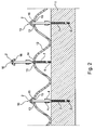
- the invention also relates to a combination of a flanged drill screw according to the invention, a base and a plate, wherein the plate is arranged to the base by the flanged drill screw, the screw extending through the plate and into the base.
- An example of such a combination is a roof with corrugated roof plates, wherein the screws are arranged in the corrugated plates at a top the wave shape.
- the plate is spaced apart from the base and the distance from the plate to the base is larger than the distance from the at least one flange to the end of the threaded portion adjacent the drill portion.
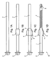
- FIG 1A the first step of an embodiment of manufacturing a drill screw according to the invention is shown.
- a shaft 1 is provided.
- This shaft has at one end a hexagonal head 2.
- this thickening 3 is then (see figure 1C ) flattened such that two flanges 4 are arranged. Due to this flattening the thickening 3 is reduced in cross section, such that it corresponds with the diameter of the remaining shaft 1. The material from this thickening 3 is used for the flanges 4.
- the shaft 1 is provided at the tip with a drill portion 6. Between the drill portion 6 and the flanges 4, a thread 7 is arranged. The resulting product is a flanged drill screw 10.
Claims (11)
- Verfahren zur Herstellung einer Flanschbohrschraube (10), wobei das Verfahren die folgenden Schritte umfasst:- Bereitstellen eines Schafts (1) mit einem Kopf (2) an einem Ende und einer freien Spitze an seinem gegenüberliegenden Ende,
gekennzeichnet durch:- Aufweiten eines Teils des Schafts derart, dass an der Länge des Schafts (1) örtlich eine Verdickung (3) gebildet wird, und- Bilden mindestens eines Flansches (4) aus der Verdickung (3). - Verfahren nach Anspruch 1, den Schritt des Anordnens eines Bohrabschnitts (6) an der Spitze des Schafts (1) umfassend.
- Verfahren nach Anspruch 2, den Schritt des Anordnens eines Gewindeabschnitts (7) am Schaft (1) zwischen der Verdickung (3) und der Spitze des Schafts (1) umfassend.
- Verfahren nach einem der vorhergehenden Ansprüche, wobei aus der Verdickung (3) zwei oder mehr Flansche (4) gebildet werden, die gleichmäßig um den Umfang des Schafts (1) verteilt sind.
- Verfahren nach einem der vorhergehenden Ansprüche, den Schritt des Reduzierens der Verdickung (3), während der Schritt des Bildens mindestens eines Flansches (4) aus der Verdickung (3) ausgeführt wird, umfassend.
- Verfahren nach Anspruch 5, wobei die Verdickung (3) auf einen Durchmesser reduziert wird, der im Wesentlichen gleich dem Durchmesser des Schafts (1) ist.
- Verfahren nach einem der vorhergehenden Ansprüche, den Schritt des Bereitstellens einer Schneidekante (5) an dem mindestens einen Flansch (4) umfassend.
- Flanschbohrschraube (10), die gemäß dem Verfahren nach einem der Ansprüche 1 bis 7 hergestellt ist, Folgendes umfassend:- einen Schaft (1) mit im Wesentlichen gleichförmigem Querschnitt,- einen Kopf (2), der an einem Ende des Schafts (1) angeordnet ist, und- mindestens einen Flansch (4), der am Schaft (1) zwischen dem Kopf (2) und dem anderen Ende des Schafts (1) angeordnet ist.
- Flanschbohrschraube (10) nach Anspruch 8, ferner Folgendes umfassend:- einen Bohrabschnitt (6) an dem anderen Ende des Schafts (1), gegenüber dem Kopf (2), und- einen Gewindeabschnitt (7), der zwischen dem Bohrabschnitt (6) und dem mindestens einen Flansch (4) angeordnet ist.
- Kombination einer Flanschbohrschraube (10) nach Anspruch 9, einer Basis (11) und einer Platte (12), wobei die Platte (12) durch die Flanschbohrschraube (10) an der Basis (11) angeordnet ist, wobei sich die Schraube (10) durch die Platte (12) und in die Basis (11) erstreckt.
- Kombination nach Anspruch 10, wobei die Platte (12) von der Basis (11) beabstandet ist und der Abstand von der Platte (12) zur Basis (11) größer ist als der Abstand von dem mindestens einen Flansch (4) zum an den Bohrabschnitt (6) angrenzenden Ende des Gewindeabschnitts (7).
Priority Applications (3)
| Application Number | Priority Date | Filing Date | Title |
|---|---|---|---|
| PL09158099T PL2241768T3 (pl) | 2009-04-16 | 2009-04-16 | Sposób wytwarzania kołnierzowego wkrętu wiercącego |
| EP09158099A EP2241768B1 (de) | 2009-04-16 | 2009-04-16 | Verfahren zur Herstellung einer Flanschdrillschraube |
| PCT/EP2010/054869 WO2010119052A1 (en) | 2009-04-16 | 2010-04-14 | Method for manufacturing a flanged drill screw |
Applications Claiming Priority (1)
| Application Number | Priority Date | Filing Date | Title |
|---|---|---|---|
| EP09158099A EP2241768B1 (de) | 2009-04-16 | 2009-04-16 | Verfahren zur Herstellung einer Flanschdrillschraube |
Publications (2)
| Publication Number | Publication Date |
|---|---|
| EP2241768A1 EP2241768A1 (de) | 2010-10-20 |
| EP2241768B1 true EP2241768B1 (de) | 2012-11-07 |
Family
ID=40852002
Family Applications (1)
| Application Number | Title | Priority Date | Filing Date |
|---|---|---|---|
| EP09158099A Not-in-force EP2241768B1 (de) | 2009-04-16 | 2009-04-16 | Verfahren zur Herstellung einer Flanschdrillschraube |
Country Status (3)
| Country | Link |
|---|---|
| EP (1) | EP2241768B1 (de) |
| PL (1) | PL2241768T3 (de) |
| WO (1) | WO2010119052A1 (de) |
Families Citing this family (2)
| Publication number | Priority date | Publication date | Assignee | Title |
|---|---|---|---|---|
| US20130216329A1 (en) * | 2010-10-22 | 2013-08-22 | Ideal Fasteners Pty Ltd | Screw fastener |
| TWM446845U (zh) * | 2012-07-30 | 2013-02-11 | Gu-Yao Chen | 浪板螺絲 |
Family Cites Families (4)
| Publication number | Priority date | Publication date | Assignee | Title |
|---|---|---|---|---|
| DE2611395C2 (de) | 1976-03-18 | 1978-02-16 | Opheis Gmbh & Co | Vorrichtung zum Befestigen profilierter Dacheindeckungsplatten auf einer Dachkonstruktion |
| DE19959672C2 (de) * | 1999-12-10 | 2002-04-18 | Sfs Ind Holding Ag Heerbrugg | Schraube zur Abstandsbefestigung von Abdeckplatten oder Schienen an einem Unterbau |
| DE10308470A1 (de) | 2003-02-20 | 2004-09-02 | Adolf Würth GmbH & Co. KG | Selbstbohrende Schraube |
| AU2008201262A1 (en) | 2007-03-15 | 2008-10-02 | Loi & Tran Pty. Limited | Roofing screw |
-
2009
- 2009-04-16 PL PL09158099T patent/PL2241768T3/pl unknown
- 2009-04-16 EP EP09158099A patent/EP2241768B1/de not_active Not-in-force
-
2010
- 2010-04-14 WO PCT/EP2010/054869 patent/WO2010119052A1/en active Application Filing
Also Published As
| Publication number | Publication date |
|---|---|
| PL2241768T3 (pl) | 2013-06-28 |
| EP2241768A1 (de) | 2010-10-20 |
| WO2010119052A1 (en) | 2010-10-21 |
Similar Documents
| Publication | Publication Date | Title |
|---|---|---|
| KR102063126B1 (ko) | 블라인드 리벳 볼트 | |
| KR101118815B1 (ko) | 하이드로 폼을 사용한 천공 방법과 천공 장치 및 하이드로 폼 가공 부품과 구조체 | |
| JP2005207594A (ja) | ブラインドリベットナット | |
| US20090092462A1 (en) | Dual-action disposable clamp | |
| CA2427201C (en) | Method of manufacturing a blind threaded insert | |
| CZ281543B6 (cs) | Šroub pro děrování a vytváření závitu | |
| US11092184B2 (en) | Installation and design of a rivnut | |
| US20100054893A1 (en) | Hollow bolt comprising a longitudinal bore | |
| US20160327081A1 (en) | Screw, fastening arrangement and use of a screw | |
| JP2020122573A (ja) | 半中空パンチリベット、半中空パンチリベットによる少なくとも2つの要素のパンチリベットジョイント、及び少なくとも2つの要素を半中空パンチリベットで連結する方法 | |
| AU2001294003A1 (en) | Method of manufacturing a blind threaded insert | |
| EP2923091B1 (de) | Verfahren und schraube zur montage von faserzementbrettern | |
| CA2329165C (en) | Method for producing a rim hole | |
| EP1710455A1 (de) | Mit Stahlblechen zu verwendende, selbstbohrende Schraube | |
| EP2241768B1 (de) | Verfahren zur Herstellung einer Flanschdrillschraube | |
| AU719725B2 (en) | Fastening screw and method of forming same | |
| EP3734086B1 (de) | Blindnietmutter, blindnietmutteranordnung und setzverfahren | |
| EP1666740A2 (de) | Blindniet | |
| US10960503B2 (en) | Staked installation method | |
| KR101080149B1 (ko) | 체결너트 및 그 제조방법 | |
| AU2006249212B2 (en) | Method of manufacturing a blind threaded insert | |
| JP2000303605A (ja) | 鋼製束とその製造方法 | |
| CN1784552A (zh) | 单面紧固件及其从工件上拆除的方法 | |
| JP2007160389A (ja) | 機械要素接合方法 | |
| JPH07238911A (ja) | 塗装取りボルト |
Legal Events
| Date | Code | Title | Description |
|---|---|---|---|
| PUAI | Public reference made under article 153(3) epc to a published international application that has entered the european phase |
Free format text: ORIGINAL CODE: 0009012 |
|
| AK | Designated contracting states |
Kind code of ref document: A1 Designated state(s): AT BE BG CH CY CZ DE DK EE ES FI FR GB GR HR HU IE IS IT LI LT LU LV MC MK MT NL NO PL PT RO SE SI SK TR |
|
| 17P | Request for examination filed |
Effective date: 20110420 |
|
| 17Q | First examination report despatched |
Effective date: 20110511 |
|
| RIC1 | Information provided on ipc code assigned before grant |
Ipc: F16B 35/04 20060101ALI20120425BHEP Ipc: F16B 25/10 20060101AFI20120425BHEP Ipc: E04D 3/36 20060101ALI20120425BHEP Ipc: B21K 1/56 20060101ALI20120425BHEP |
|
| GRAP | Despatch of communication of intention to grant a patent |
Free format text: ORIGINAL CODE: EPIDOSNIGR1 |
|
| RIN1 | Information on inventor provided before grant (corrected) |
Inventor name: MEILINK, GERRIT JOHAN |
|
| GRAS | Grant fee paid |
Free format text: ORIGINAL CODE: EPIDOSNIGR3 |
|
| GRAA | (expected) grant |
Free format text: ORIGINAL CODE: 0009210 |
|
| AK | Designated contracting states |
Kind code of ref document: B1 Designated state(s): AT BE BG CH CY CZ DE DK EE ES FI FR GB GR HR HU IE IS IT LI LT LU LV MC MK MT NL NO PL PT RO SE SI SK TR |
|
| REG | Reference to a national code |
Ref country code: GB Ref legal event code: FG4D |
|
| REG | Reference to a national code |
Ref country code: CH Ref legal event code: EP Ref country code: AT Ref legal event code: REF Ref document number: 583131 Country of ref document: AT Kind code of ref document: T Effective date: 20121115 |
|
| REG | Reference to a national code |
Ref country code: IE Ref legal event code: FG4D |
|
| REG | Reference to a national code |
Ref country code: DE Ref legal event code: R096 Ref document number: 602009010959 Country of ref document: DE Effective date: 20130103 |
|
| REG | Reference to a national code |
Ref country code: RO Ref legal event code: EPE |
|
| REG | Reference to a national code |
Ref country code: NL Ref legal event code: T3 |
|
| REG | Reference to a national code |
Ref country code: AT Ref legal event code: MK05 Ref document number: 583131 Country of ref document: AT Kind code of ref document: T Effective date: 20121107 |
|
| REG | Reference to a national code |
Ref country code: LT Ref legal event code: MG4D |
|
| PG25 | Lapsed in a contracting state [announced via postgrant information from national office to epo] |
Ref country code: HR Free format text: LAPSE BECAUSE OF FAILURE TO SUBMIT A TRANSLATION OF THE DESCRIPTION OR TO PAY THE FEE WITHIN THE PRESCRIBED TIME-LIMIT Effective date: 20121107 Ref country code: SE Free format text: LAPSE BECAUSE OF FAILURE TO SUBMIT A TRANSLATION OF THE DESCRIPTION OR TO PAY THE FEE WITHIN THE PRESCRIBED TIME-LIMIT Effective date: 20121107 Ref country code: FI Free format text: LAPSE BECAUSE OF FAILURE TO SUBMIT A TRANSLATION OF THE DESCRIPTION OR TO PAY THE FEE WITHIN THE PRESCRIBED TIME-LIMIT Effective date: 20121107 Ref country code: IS Free format text: LAPSE BECAUSE OF FAILURE TO SUBMIT A TRANSLATION OF THE DESCRIPTION OR TO PAY THE FEE WITHIN THE PRESCRIBED TIME-LIMIT Effective date: 20130307 Ref country code: NO Free format text: LAPSE BECAUSE OF FAILURE TO SUBMIT A TRANSLATION OF THE DESCRIPTION OR TO PAY THE FEE WITHIN THE PRESCRIBED TIME-LIMIT Effective date: 20130207 Ref country code: LT Free format text: LAPSE BECAUSE OF FAILURE TO SUBMIT A TRANSLATION OF THE DESCRIPTION OR TO PAY THE FEE WITHIN THE PRESCRIBED TIME-LIMIT Effective date: 20121107 |
|
| PG25 | Lapsed in a contracting state [announced via postgrant information from national office to epo] |
Ref country code: PT Free format text: LAPSE BECAUSE OF FAILURE TO SUBMIT A TRANSLATION OF THE DESCRIPTION OR TO PAY THE FEE WITHIN THE PRESCRIBED TIME-LIMIT Effective date: 20130307 Ref country code: SI Free format text: LAPSE BECAUSE OF FAILURE TO SUBMIT A TRANSLATION OF THE DESCRIPTION OR TO PAY THE FEE WITHIN THE PRESCRIBED TIME-LIMIT Effective date: 20121107 Ref country code: GR Free format text: LAPSE BECAUSE OF FAILURE TO SUBMIT A TRANSLATION OF THE DESCRIPTION OR TO PAY THE FEE WITHIN THE PRESCRIBED TIME-LIMIT Effective date: 20130208 Ref country code: LV Free format text: LAPSE BECAUSE OF FAILURE TO SUBMIT A TRANSLATION OF THE DESCRIPTION OR TO PAY THE FEE WITHIN THE PRESCRIBED TIME-LIMIT Effective date: 20121107 |
|
| PG25 | Lapsed in a contracting state [announced via postgrant information from national office to epo] |
Ref country code: AT Free format text: LAPSE BECAUSE OF FAILURE TO SUBMIT A TRANSLATION OF THE DESCRIPTION OR TO PAY THE FEE WITHIN THE PRESCRIBED TIME-LIMIT Effective date: 20121107 |
|
| REG | Reference to a national code |
Ref country code: PL Ref legal event code: T3 |
|
| PG25 | Lapsed in a contracting state [announced via postgrant information from national office to epo] |
Ref country code: EE Free format text: LAPSE BECAUSE OF FAILURE TO SUBMIT A TRANSLATION OF THE DESCRIPTION OR TO PAY THE FEE WITHIN THE PRESCRIBED TIME-LIMIT Effective date: 20121107 Ref country code: CZ Free format text: LAPSE BECAUSE OF FAILURE TO SUBMIT A TRANSLATION OF THE DESCRIPTION OR TO PAY THE FEE WITHIN THE PRESCRIBED TIME-LIMIT Effective date: 20121107 Ref country code: DK Free format text: LAPSE BECAUSE OF FAILURE TO SUBMIT A TRANSLATION OF THE DESCRIPTION OR TO PAY THE FEE WITHIN THE PRESCRIBED TIME-LIMIT Effective date: 20121107 Ref country code: BG Free format text: LAPSE BECAUSE OF FAILURE TO SUBMIT A TRANSLATION OF THE DESCRIPTION OR TO PAY THE FEE WITHIN THE PRESCRIBED TIME-LIMIT Effective date: 20130207 Ref country code: SK Free format text: LAPSE BECAUSE OF FAILURE TO SUBMIT A TRANSLATION OF THE DESCRIPTION OR TO PAY THE FEE WITHIN THE PRESCRIBED TIME-LIMIT Effective date: 20121107 |
|
| PG25 | Lapsed in a contracting state [announced via postgrant information from national office to epo] |
Ref country code: IT Free format text: LAPSE BECAUSE OF FAILURE TO SUBMIT A TRANSLATION OF THE DESCRIPTION OR TO PAY THE FEE WITHIN THE PRESCRIBED TIME-LIMIT Effective date: 20121107 |
|
| PLBE | No opposition filed within time limit |
Free format text: ORIGINAL CODE: 0009261 |
|
| STAA | Information on the status of an ep patent application or granted ep patent |
Free format text: STATUS: NO OPPOSITION FILED WITHIN TIME LIMIT |
|
| 26N | No opposition filed |
Effective date: 20130808 |
|
| PG25 | Lapsed in a contracting state [announced via postgrant information from national office to epo] |
Ref country code: ES Free format text: LAPSE BECAUSE OF FAILURE TO SUBMIT A TRANSLATION OF THE DESCRIPTION OR TO PAY THE FEE WITHIN THE PRESCRIBED TIME-LIMIT Effective date: 20130218 |
|
| PG25 | Lapsed in a contracting state [announced via postgrant information from national office to epo] |
Ref country code: MC Free format text: LAPSE BECAUSE OF FAILURE TO SUBMIT A TRANSLATION OF THE DESCRIPTION OR TO PAY THE FEE WITHIN THE PRESCRIBED TIME-LIMIT Effective date: 20121107 Ref country code: CY Free format text: LAPSE BECAUSE OF FAILURE TO SUBMIT A TRANSLATION OF THE DESCRIPTION OR TO PAY THE FEE WITHIN THE PRESCRIBED TIME-LIMIT Effective date: 20121107 |
|
| REG | Reference to a national code |
Ref country code: CH Ref legal event code: PL |
|
| REG | Reference to a national code |
Ref country code: DE Ref legal event code: R097 Ref document number: 602009010959 Country of ref document: DE Effective date: 20130808 |
|
| REG | Reference to a national code |
Ref country code: IE Ref legal event code: MM4A |
|
| PG25 | Lapsed in a contracting state [announced via postgrant information from national office to epo] |
Ref country code: LI Free format text: LAPSE BECAUSE OF NON-PAYMENT OF DUE FEES Effective date: 20130430 Ref country code: CH Free format text: LAPSE BECAUSE OF NON-PAYMENT OF DUE FEES Effective date: 20130430 |
|
| PG25 | Lapsed in a contracting state [announced via postgrant information from national office to epo] |
Ref country code: IE Free format text: LAPSE BECAUSE OF NON-PAYMENT OF DUE FEES Effective date: 20130416 |
|
| PG25 | Lapsed in a contracting state [announced via postgrant information from national office to epo] |
Ref country code: MT Free format text: LAPSE BECAUSE OF FAILURE TO SUBMIT A TRANSLATION OF THE DESCRIPTION OR TO PAY THE FEE WITHIN THE PRESCRIBED TIME-LIMIT Effective date: 20121107 |
|
| REG | Reference to a national code |
Ref country code: FR Ref legal event code: PLFP Year of fee payment: 7 |
|
| PG25 | Lapsed in a contracting state [announced via postgrant information from national office to epo] |
Ref country code: TR Free format text: LAPSE BECAUSE OF FAILURE TO SUBMIT A TRANSLATION OF THE DESCRIPTION OR TO PAY THE FEE WITHIN THE PRESCRIBED TIME-LIMIT Effective date: 20121107 |
|
| PGFP | Annual fee paid to national office [announced via postgrant information from national office to epo] |
Ref country code: NL Payment date: 20150417 Year of fee payment: 7 |
|
| PG25 | Lapsed in a contracting state [announced via postgrant information from national office to epo] |
Ref country code: MK Free format text: LAPSE BECAUSE OF FAILURE TO SUBMIT A TRANSLATION OF THE DESCRIPTION OR TO PAY THE FEE WITHIN THE PRESCRIBED TIME-LIMIT Effective date: 20121107 Ref country code: HU Free format text: LAPSE BECAUSE OF FAILURE TO SUBMIT A TRANSLATION OF THE DESCRIPTION OR TO PAY THE FEE WITHIN THE PRESCRIBED TIME-LIMIT; INVALID AB INITIO Effective date: 20090416 Ref country code: LU Free format text: LAPSE BECAUSE OF NON-PAYMENT OF DUE FEES Effective date: 20130416 |
|
| PGFP | Annual fee paid to national office [announced via postgrant information from national office to epo] |
Ref country code: RO Payment date: 20150406 Year of fee payment: 7 Ref country code: GB Payment date: 20150424 Year of fee payment: 7 Ref country code: DE Payment date: 20150424 Year of fee payment: 7 |
|
| PGFP | Annual fee paid to national office [announced via postgrant information from national office to epo] |
Ref country code: BE Payment date: 20150417 Year of fee payment: 7 Ref country code: PL Payment date: 20150407 Year of fee payment: 7 Ref country code: FR Payment date: 20150430 Year of fee payment: 7 |
|
| PG25 | Lapsed in a contracting state [announced via postgrant information from national office to epo] |
Ref country code: BE Free format text: LAPSE BECAUSE OF NON-PAYMENT OF DUE FEES Effective date: 20160430 |
|
| REG | Reference to a national code |
Ref country code: DE Ref legal event code: R119 Ref document number: 602009010959 Country of ref document: DE |
|
| REG | Reference to a national code |
Ref country code: NL Ref legal event code: MM Effective date: 20160501 |
|
| GBPC | Gb: european patent ceased through non-payment of renewal fee |
Effective date: 20160416 |
|
| REG | Reference to a national code |
Ref country code: FR Ref legal event code: ST Effective date: 20161230 |
|
| PG25 | Lapsed in a contracting state [announced via postgrant information from national office to epo] |
Ref country code: FR Free format text: LAPSE BECAUSE OF NON-PAYMENT OF DUE FEES Effective date: 20160502 Ref country code: GB Free format text: LAPSE BECAUSE OF NON-PAYMENT OF DUE FEES Effective date: 20160416 Ref country code: NL Free format text: LAPSE BECAUSE OF NON-PAYMENT OF DUE FEES Effective date: 20160501 Ref country code: DE Free format text: LAPSE BECAUSE OF NON-PAYMENT OF DUE FEES Effective date: 20161101 Ref country code: RO Free format text: LAPSE BECAUSE OF NON-PAYMENT OF DUE FEES Effective date: 20160416 |
|
| PG25 | Lapsed in a contracting state [announced via postgrant information from national office to epo] |
Ref country code: PL Free format text: LAPSE BECAUSE OF NON-PAYMENT OF DUE FEES Effective date: 20160416 |