EP2241692B1 - House module, assembly and house of a number of house modules, and method for manufacturing a house - Google Patents
House module, assembly and house of a number of house modules, and method for manufacturing a house Download PDFInfo
- Publication number
- EP2241692B1 EP2241692B1 EP10159843A EP10159843A EP2241692B1 EP 2241692 B1 EP2241692 B1 EP 2241692B1 EP 10159843 A EP10159843 A EP 10159843A EP 10159843 A EP10159843 A EP 10159843A EP 2241692 B1 EP2241692 B1 EP 2241692B1
- Authority
- EP
- European Patent Office
- Prior art keywords
- house
- bottom wall
- ceiling wall
- reinforcing ribs
- house module
- Prior art date
- Legal status (The legal status is an assumption and is not a legal conclusion. Google has not performed a legal analysis and makes no representation as to the accuracy of the status listed.)
- Not-in-force
Links
- 238000000034 method Methods 0.000 title claims abstract description 19
- 238000004519 manufacturing process Methods 0.000 title claims abstract description 18
- 230000003014 reinforcing effect Effects 0.000 claims abstract description 116
- 238000005266 casting Methods 0.000 claims description 17
- 239000007788 liquid Substances 0.000 claims description 2
- 238000010276 construction Methods 0.000 abstract description 3
- 230000000712 assembly Effects 0.000 description 3
- 238000000429 assembly Methods 0.000 description 3
- 230000008878 coupling Effects 0.000 description 3
- 238000010168 coupling process Methods 0.000 description 3
- 238000005859 coupling reaction Methods 0.000 description 3
- 230000002349 favourable effect Effects 0.000 description 2
- 230000005540 biological transmission Effects 0.000 description 1
- 230000015572 biosynthetic process Effects 0.000 description 1
- 230000005611 electricity Effects 0.000 description 1
- 239000000463 material Substances 0.000 description 1
- 238000005192 partition Methods 0.000 description 1
- 230000008092 positive effect Effects 0.000 description 1
- 238000003908 quality control method Methods 0.000 description 1
- 230000002787 reinforcement Effects 0.000 description 1
- 238000009877 rendering Methods 0.000 description 1
Images


Classifications
-
- E—FIXED CONSTRUCTIONS
- E04—BUILDING
- E04B—GENERAL BUILDING CONSTRUCTIONS; WALLS, e.g. PARTITIONS; ROOFS; FLOORS; CEILINGS; INSULATION OR OTHER PROTECTION OF BUILDINGS
- E04B1/00—Constructions in general; Structures which are not restricted either to walls, e.g. partitions, or floors or ceilings or roofs
- E04B1/348—Structures composed of units comprising at least considerable parts of two sides of a room, e.g. box-like or cell-like units closed or in skeleton form
- E04B1/34815—Elements not integrated in a skeleton
- E04B1/34823—Elements not integrated in a skeleton the supporting structure consisting of concrete
Definitions
- the invention relates to a house module as defined by claim 1, an assembly of a number of house modules for forming a house as defined by claim 10, a house comprising a number of house module as defined by claim 12 and to a method for manufacturing a house as defined by claim 13.
- DE-2926969 discloses a house module which is provided with three sidewalls, a bottom wall and a ceiling wall. As a result of the three sidewalls, the known house module is not suitable to be placed in series one behind the other for forming a boundary of a larger living space.
- This known house module is provided with bottom wall reinforcing ribs and ceiling wall reinforcing ribs which form an integral part of the bottom wall and the ceiling wall, respectively.
- the bottom wall reinforcing ribs of the second house module extend next to the ceiling wall reinforcing ribs of the first house module. Between neighbouring reinforcing ribs of a bottom wall and a ceiling wall, there is a space in which pipes can be received.
- NL-1024512 discloses a method for constructing a building.
- house modules are manufactured which are subsequently joined for forming the building.
- both a bottom wall and a ceiling wall thereof are self-supporting.
- the house modules can be stacked one on top of the other in a fairly simple manner.
- a drawback of the self-supporting nature of both the bottom wall and the ceiling wall is that these walls are relatively thick and must be reinforced. Therefore, a bottom wall/ceiling wall combination which is formed when stacking the two known house modules is relatively thick. This relatively great thickness leads to an increased building height, which leads to a larger building volume.
- a larger building volume leads to increased costs, for instance in that outside covering, such as, for instance, facework is to be provided on the outer walls.
- NL1029449 proposes a solution to this problem in that in there, the ceiling wall is of relatively thin design and is provided with an upwards projecting coupling element.
- the ceilings are to be temporarily supported by means of, for instance, building stays or props.
- the fact is that the ceiling wall is not self-supporting.
- the projecting coupling elements are connected to coupling elements provided in the bottom wall of the second module.
- sufficient robustness is provided to the ceiling wall of the underlying module which is then suspended, as is were, from the self-supporting bottom wall of the second module. Thereupon, the temporary support can be removed.
- the object of the invention is an alternative solution to a house module which combines the advantages of the two known systems.
- a house module is envisaged which, upon stacking, allows for the feed-through of pipes in different directions between the ceiling wall and bottom wall bounding one another.
- the invention provides a house module which is suitable for forming a house through combination with at least one similar house module, the house module comprising:
- the invention also provides an assembly of a number of such house modules for forming a house.
- the invention further provides a house which comprises such an assembly and is built up therefrom.
- the invention provides a method for manufacturing a house, comprising:
- both the bottom wall and the ceiling wall are self-supporting. Therefore, there is no need to provide temporary support of the ceiling wall during transport of the house module. Nor is there the above-described risk of collapse due to incorrect assembling order.
- the bottom wall reinforcing ribs are provided in a manner staggered relative to the ceiling wall reinforcing ribs, they extend next to each other when two housing modules are stacked one on top of the other. When stacking, the height of the bottom wall reinforcing ribs and the ceiling wall reinforcing ribs is therefore not added up.
- the thickness of a ceiling wall/bottom wall combination that is formed upon stacking may be smaller than with the self-supporting ceiling wall and bottom wall constructions known from NL-1024512 .
- This will result in a proportionally smaller building height and building volume with all associated financial advantages, while between a ceiling wall and a bottom wall, still, spaces are present between the neighbouring reinforcing ribs for feeding through pipes and wiring.
- both the bottom wall and the ceiling wall are self-supporting, in one embodiment, there may be no contact at all between bottom wall and ceiling wall, upon stacking. This may be the case when the house modules rest on each other by their sidewalls. In such an embodiment, no contact sounds are transmitted via the bottom wall and the ceiling wall.
- Feeding through pipes such as, for instance, even drains of a toilet in a direction parallel to the tube central axis is possible through the first channel recess.
- This has as an advantage that a free positioning option is provided in the direction of the tube central axis of objects that are provided with feed pipes and discharge pipes, such as, for instance, a toilet, a tap, a bath tub, a power point, an electricity switch, etc.
- the second channel recesses between neighbouring reinforcing ribs which therefore extend perpendicularly to the tube central axis, can be used for feed-through of pipes, such as even a drain of a toilet.
- a great freedom of positioning is provided also in a direction perpendicular to the tube central axis for objects that are provided with feed pipes and/or drain pipes of which examples are mentioned hereinabove.
- FR-1.414.158 disclosing the features of the preamble of claim 1, describes a prefabricated house module with two sidewalls, a bottom wall and a ceiling wall.
- the known house module is provided with bottom wall reinforcing ribs and ceiling wall reinforcing ribs which form an integral part of the bottom wall and the ceiling wall, respectively.
- the bottom wall reinforcing ribs are not all arranged in a manner staggered relative to the ceiling wall reinforcing ribs, so that, when stacking two house modules, the thickness of a ceiling wall/bottom wall combination is determined by the sum of thicknesses of the ceiling wall, the bottom wall and the heights of a ceiling wall reinforcing rib and a bottom wall reinforcing rib.
- An important advantage that is envisaged by the invention is therefore not achieved with this known device.
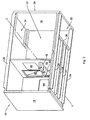
- Figs. 1 and 2 show an example of an embodiment of house module 10 which is suitable for forming a house through combination with at least one similar house module 10.
- house can mean different types of living units, such as a terraced house, a semi-detached house, a detached house and an apartment.
- the embodiment of the house module 10 comprises a bottom wall 12 from concrete and a ceiling wall 14 from concrete which extends parallel to the bottom wall 12.
- the embodiment further comprises a first sidewall 16 from concrete which extends perpendicularly to the bottom wall 12 and a second sidewall 18 from concrete which extends parallel to the first sidewall 16.
- the walls form together a concrete, tubular section 20 which bounds a tube inside space 22 and which has an imaginary tube central axis L which extends parallel to the walls 12-18 and runs through a geometrical centre of the tube inside space 22.
- the embodiment of the house module 10 is further provided with bottom wall reinforcing ribs 24 which form an integral part of the bottom wall 12.
- the bottom wall reinforcing ribs 24 extend perpendicularly to the tube central axis L from the first sidewall 16 in the direction of the second sidewall 18. It is clearly visible that the bottom wall reinforcing ribs 24 are provided on a side of the bottom wall 12 remote from the tube inside space 22.
- the embodiment is further provided with ceiling wall reinforcing ribs 26 which form an integral part of the ceiling wall 14.
- the ceiling wall reinforcing ribs 26 extend perpendicularly to the tube central axis L from the first sidewall 16 in the direction of the second sidewall 18.
- the ceiling wall reinforcing ribs 26 too are provided on a side of the ceiling wall 14 remote from the tube inside space 22. Viewed in the direction of the tube central axis L, the bottom wall reinforcing ribs 24 are provided in a manner staggered relative to the ceiling wall reinforcing ribs 26 so that, when a second house module 10' is placed on a first house module 10, the bottom wall reinforcing ribs 24' of the second house module 10' extend next to the ceiling wall reinforcing ribs 26 of the first house module 10.
- the staggered positioning of the bottom wall reinforcing ribs 24' of the second house module 10' relative to the ceiling wall reinforcing ribs 26 of the first house module 10 is clearly visible in fig. 5 .
- a thus designed house module 10 has as an advantage that both the bottom wall 12 and the ceiling wall 14 thereof are self-supporting as a result of the presence of the bottom wall reinforcing ribs 24 and the ceiling wall reinforcing ribs 26.
- the total thickness of a ceiling wall/bottom wall combination upon stacking of the two house modules 10, 10' can still remain relatively limited in that, viewed in the direction of the tube central axis L, the bottom wall reinforcing ribs 24 are provided in a manner staggered relative to the ceiling wall reinforcing ribs 26.
- a relatively small building height and a relatively small building volume is obtained, which, from a point of view of costs, is particularly advantageous.
- a feed-through space for pipes between the bottom wall and the ceiling wall is provided.
- the house module Owing to the thin design of the bottom wall and the ceiling wall, the house module is furthermore lighter, which is favourable upon transport and leads to further reduced transport costs.
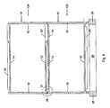
- Fig. 3 shows a single house module 10 in a top plan view. A number of such house modules 10 can be placed next to each other and form a first story 102; see to that end fig. 5 .
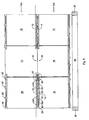
- cross sections IV-IV and V-V are indicated.
- the cross sections represented in Figs. 4 and 5 show two stories 102, 104 which each consist of three house modules 10, 10' of which only one is represented in the top plan view of Fig. 3 .
- the various elements of the house modules 10' of the second story 104 are provided with primed reference numerals. It is clear that in alternative embodiments, a story 102, 104 can consist of more than three or less than three house modules 10, 10'.
- Figs. 5 and 7 clearly show that neighbouring house modules 10, 10' can be mutually interconnected by means of, for instance, nut/bolt assemblies 49.
- the house modules 10' of a second story 104 can also be connected by means of nut/bolt assemblies (not shown) to house modules 10 of the first story 102, this is, however, not necessary.
- the dimensions of the house modules 10, 10' can vary also. When the width direction is defined parallel to the tube central axis L, a tube width of, for instance, 3 m can be considered.
- the outside dimensions from the first sidewall 16 to the second sidewall 18 can, for instance, be 4.5 to 7 meters.
- a house module 10 of such dimensions can very well be transported by road with the aid of a truck.
- the top of the bottom wall 12' of the second story 104 can be, for instance, approximately 3.1 m above ground level.
- special end modules can be provided having a width of 1.5 meters and provided with an outer wall for closing the end face of the tubular end module.
- two end modules can be transported one next to the other on one truck without this truck being locally loaded due to the presence of the outer wall.
- the fact is that the two end modules can be placed on the truck mirror symmetrically relative to a central longitudinal axis of the truck and can balance each other.
- both the bottom wall reinforcing ribs 24 and the ceiling wall reinforcing ribs 26 can end at a distance from the second sidewall 18 so that at that location, in a condition of two house modules 10, 10' stacked one on the other, a first channel recess 28 is formed which extends parallel to the tube central axis L. This is clearly visible in Figs. 4 and 6 . Feeding through pipes, such as, for instance, even toilet drains, is an option through the first channel recess 28.
- first channel recess 28 can also be provided at a distance from the second sidewall 118, while then, the bottom wall reinforcing ribs 24 and the ceiling wall reinforcing ribs 26 extend on both sides of the first channel recess 28.
- the advantage of a first channel recess 28 near the second sidewall 18 is that with such a configuration, the bottom wall 12 and the ceiling wall 14 will have optimal rigidity and strength.
- the width of the bottom wall reinforcing ribs 24 and the ceiling wall reinforcing ribs 26 can be such that in a condition of two house modules 10, 10' stacked one on the other, between at least one pair of a ceiling wall reinforcing rib 26 and a neighbouring bottom wall reinforcing rib 24' a second channel recess 30 is formed which extends perpendicularly to the tube central axis L.
- the second channel recesses 30 too can be used for feeding through pipes, such as even a toilet drain.
- a good freedom of positioning is provided for objects which are provided with feed and/or drain pipes of which examples are mentioned hereinabove.
- the first and the second sidewalls 16, 18 can extend not only between the bottom wall 12 and the ceiling wall 14, but also slightly beyond at least one of the bottom wall 12 and the ceiling wall 14 on a side of this or these walls remote from the tube inside space 22 such that in a condition of two house modules 10, 10' stacked one on the other, the overlying house module 10' rests by the first and second sidewalls 16', 18' thereof on the underlying house module 10.
- a better defined positioning is enabled at the location of the first and the second sidewalls 16, 18, 16', 18' only.
- the risk that the connection is over-defined, like with a table with four legs, is limited so that the risk of an overlying house module 10 "wobbling" on the lower house module 10 is minimized.
- a layer of compressible material can be included for rendering stacking more stable.
- first and the second sidewalls 16, 18 each extend somewhat beyond both the bottom wall 12 and the ceiling wall 14 on the sides of this ceiling wall 14 and the bottom wall 12 remote from the tube inside space 22.
- the clearance P between the ceiling wall reinforcing ribs 26 of the underlying house module 10 and the bottom wall 12' of the overlying house module 10' can be in the range of 1 - 3 cm.
- the clearance P between the bottom wall reinforcing ribs 24' of the overlying house module 10' and the ceiling wall 14 of the underlying house module 10 can be in the range of 1 - 3 cm.
- the clearance P can be, for instance, 2 cm.
- the bottom wall 12 can have a thickness in the range of 6 - 10 cm.
- the bottom wall reinforcing ribs 24 can have height from the bottom wall 12, in the range of 12 - 16 cm.
- the ceiling wall 14 can have a thickness in the range of 6 - 10 cm.
- the ceiling wall reinforcing ribs 26 can have a height from the ceiling wall 16 in the range of 12 - 16 cm.
- the total thickness of a ceiling wall/bottom wall combination of two house modules 10, 10' placed one on the other including the above-mentioned clearance P can be in the range of 25 - 37 cm.
- the bottom wall 12 and the ceiling wall 14 can each have a thickness of 8 cm.
- the bottom wall reinforcing ribs 24 can have a height from the bottom wall 12 of 14 cm and the ceiling wall reinforcing ribs 26 can have a height from the ceiling wall 14 of 14 cm.
- the total thickness of this ceiling wall/bottom wall combination of two house modules 10, 10' placed one on the other including the above-mentioned clearance P can then be, for instance, 32 cm.
- Such a construction has sufficient rigidity and stiffness both during transport of the house module 10 and after assembly of the various house modules 10, 10' for forming a house.
- At least one of the bottom wall 12 and the ceiling wall 14 can be provided with a stairwell recess 32, 34.
- the ceiling wall 14 or the bottom wall 12 in which the stairwell recess 32, 34 is provided can be provided with at least one transverse reinforcing rib 36 which extends parallel to the tube central axis L and which bounds the stairwell recess 32, 34.
- the middle two bottom wall reinforcing ribs 24 and ceiling wall reinforcing ribs 26 extend from the transverse reinforcing rib 36.
- middle reinforcing ribs 24, 26 it holds that they extend from the first sidewall 16 at least in as far as there is a bottom wall 12 or ceiling wall 145 available there. Owing to the presence of the transverse reinforcing rib 36 and the bottom wall reinforcing ribs 24 and ceiling wall reinforcing ribs 26 linking up therewith, despite the limited thickness of these walls, still, a bottom wall 12 and a ceiling wall 14 are provided with sufficient rigidity and strength to be self-supporting.
- both the bottom wall reinforcing ribs 24 and the ceiling wall reinforcing ribs 26 end at a distance from the second sidewall 18, so that at that location, in a condition of two house modules 10, 10' stacked one on the other, the channel recess 28 is formed which extends parallel to the tube central axis L, it is advantageous from a point of view of rigidity and strength, that the stairwell recesses 32, 34 of the two house modules 10, 10' are provided near the first sidewall 16, 16'.
- the tubular section 20 is a unitary moulded unit.
- a unitary moulded house module 10 can be advantageous.
- mass production a cost advantage can be obtained.
- the sidewalls 16, 18, the bottom wall 12 and the ceiling wall 14 could be manufactured separately in a factory and then, in the factory, be interconnected for forming the tubular section 20. With smaller, special series this could be advantageous because then, no relatively expensive casting mould is to be provided but relatively simple moulds can suffice. Although, then, assembly operations are required for interconnecting the different walls for forming the tubular section 20.
- an assembly of a number of house modules 10, 10' is provided, of which embodiments are described hereinabove, for forming a house 100.
- Such assemblies can be centrally manufactured and then be transported to a building site.
- such an assembly can also comprise a folding roof 50 (see fig. 9 ), which is provided with two hingedly interconnected roof parts 52, 54 which abut against each other in collapsed condition and form a saddle roof 50 in assembled condition.
- a folding roof 50 see fig. 9
- two hingedly interconnected roof parts 52, 54 which abut against each other in collapsed condition and form a saddle roof 50 in assembled condition.
- a house 100 which comprises an assembly as described hereinabove, and which is built up therefrom.
- An example of an embodiment of such a house 100 is shown in Fig. 9 .
- the house module 10 can also be provided with interior elements, such as one or more partition walls 40, washbasins 42, bathtubs 44, doors 46, windows 48, wall and floor tiles, and stairs. These interior elements can be provided at a central location, usually in a factory, before the house module 10 is transported to a building site. This has a very positive effect on the completion time required for finishing the house on the building site.
- An embodiment of this method comprises:
- Such a method has a favourable effect on the completion on the building site, on quality control and on costs.
- Figs. 4 and 5 show an example of an embodiment of a house 100 that can be obtained with the aid of the method.
- the method also comprises positioning a number of house modules 10' on the first story for forming a next story 104.
- a house 100 provided with a saddle roof 50 of which an example is shown in fig. 9 , can be obtained with an embodiment of the method as described hereinabove, which then comprises:
- a house 100 provided with a saddle roof 50 can be manufactured on the building site in a particularly rapid and effective manner.
- a house or a block of flats with a flat roof can be manufactured.
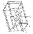
- central manufacture of one of the number of house modules 10, 10' can comprise providing a casting mould 200 which contains a mould cavity.
- a casting mould 200 which contains a mould cavity.
- An example of an embodiment of such a casting mould is shown in fig. 8 .
- the mould cavity can be provided with a bottom wall cavity 212 and a ceiling wall cavity 214 which extends parallel to the bottom wall cavity 212.
- the mould cavity can further comprise a first sidewall cavity 216 which extends perpendicularly to the bottom wall cavity 212 and a second sidewall cavity 218 which extends parallel to the first sidewall cavity 216.
- the wall cavities 212 - 218 can together form a unitary section tube cavity 220 which has an imaginary tube central axis L which extends parallel to the wall cavities 212 - 218 and runs through a geometrical centre of the section tube cavity 220.
- the section tube cavity 220 can also contain bottom wall reinforcing rib recesses 224 which form an integral part of the bottom wall cavity 212, which extend perpendicularly to the tube central axis L from the first sidewall cavity 216 in the direction of the second sidewall cavity 218, and which are provided on a side of the bottom wall cavity 212 remote from the tube inside space.
- the section tube cavity 220 can further contain ceiling wall reinforcing rib recesses (not shown) which form an integral part of the ceiling wall cavity 214, which extends perpendicularly to the tube central axis L from the first sidewall cavity 216 in the direction of the second sidewall cavity 218, and which are provided on a side of the ceiling wall cavity 214 remote from the tube inside space.
- the bottom wall reinforcing rib cavities 224 can be provided in a manner staggered relative to the ceiling wall reinforcing rib cavities so that, when a second house module 10' formed with such a casting mould is placed on a first house module 10 formed with such a casting mould, the bottom wall reinforcing ribs 24' of the second house module 10' extend next to the ceiling wall reinforcing ribs 26 of the first house module 10.
- the embodiment for manufacturing the house module 10, 10' at a central location can further comprise arranging the casting mould 200 such that the tube central axis L extends perpendicularly to a horizontal floor surface H.
- the section tube cavity 220 can be filled with liquid concrete.
- the concrete thus provided in the section tube cavity 220 can then be left to harden.
- the casting mould 200 can be removed for obtaining the hardened concrete, tubular house module 10, 10'.
- tubular house module 10, 10' can then be tilted, so that the bottom wall 12 and the ceiling wall 14 of the house module 10, 10' extend in a horizontal plane.
- this can be provided with a filling opening 202 adjacent an underside thereof, with filling taking place via this filling opening 202.
- Filling the section tube cavity 220 with concrete from the underside has as an advantage that the risk of the formation of air inclusions in the concrete is minimized.
- reinforcement can be placed in the casting mould 200. This leads to bottom walls, ceiling walls and sidewalls 12, 14, 16, 18 with high rigidity and great strength.
Landscapes
- Engineering & Computer Science (AREA)
- Architecture (AREA)
- Physics & Mathematics (AREA)
- Electromagnetism (AREA)
- Civil Engineering (AREA)
- Structural Engineering (AREA)
- Residential Or Office Buildings (AREA)
- Forms Removed On Construction Sites Or Auxiliary Members Thereof (AREA)
- Panels For Use In Building Construction (AREA)
- Load-Bearing And Curtain Walls (AREA)
Priority Applications (1)
| Application Number | Priority Date | Filing Date | Title |
|---|---|---|---|
| PL10159843T PL2241692T3 (pl) | 2009-04-15 | 2010-04-14 | Moduł domu, zespół oraz dom złożony z wielu modułów domu, oraz sposób wytwarzania domu |
Applications Claiming Priority (1)
| Application Number | Priority Date | Filing Date | Title |
|---|---|---|---|
| NL2002754A NL2002754C2 (nl) | 2009-04-15 | 2009-04-15 | Woningmodule, samenstel en woning van een aantal woningmodulen en werkwijze voor het vervaardigen van een woning. |
Publications (3)
| Publication Number | Publication Date |
|---|---|
| EP2241692A2 EP2241692A2 (en) | 2010-10-20 |
| EP2241692A3 EP2241692A3 (en) | 2010-12-15 |
| EP2241692B1 true EP2241692B1 (en) | 2011-10-19 |
Family
ID=41328648
Family Applications (1)
| Application Number | Title | Priority Date | Filing Date |
|---|---|---|---|
| EP10159843A Not-in-force EP2241692B1 (en) | 2009-04-15 | 2010-04-14 | House module, assembly and house of a number of house modules, and method for manufacturing a house |
Country Status (6)
| Country | Link |
|---|---|
| EP (1) | EP2241692B1 (pl) |
| AT (1) | ATE529575T1 (pl) |
| DK (1) | DK2241692T3 (pl) |
| ES (1) | ES2374525T3 (pl) |
| NL (1) | NL2002754C2 (pl) |
| PL (1) | PL2241692T3 (pl) |
Families Citing this family (4)
| Publication number | Priority date | Publication date | Assignee | Title |
|---|---|---|---|---|
| GB2586619B (en) * | 2019-08-29 | 2022-02-23 | Parnall Bio Engineering Ltd | Structural module for a frameless building |
| DE102021132280A1 (de) | 2021-12-08 | 2023-06-15 | Kim Baarspul | Bauelementsatz zur Herstellung von Gebäuden |
| DE102023105051A1 (de) | 2023-03-01 | 2024-09-05 | Kim Baarspul | Bauelementsatz zur Herstellung von Gebäuden |
| NL2034781B1 (en) | 2023-05-08 | 2024-11-25 | Zja B V | Modular building elements |
Family Cites Families (4)
| Publication number | Priority date | Publication date | Assignee | Title |
|---|---|---|---|---|
| FR1414158A (fr) * | 1964-10-16 | 1965-10-15 | Construction de bâtiments à l'aide d'éléments cellulaires tridimensionnels préfabriqués | |
| IT1103969B (it) | 1978-07-06 | 1985-10-14 | Maioli Amos | Cella modulare prefabbricata a forma di parallelepipedo cavo per la formazione di complessi abitabili ad uso privato o pubblico |
| NL1024512C2 (nl) | 2003-10-10 | 2005-04-12 | Emiel Willem Karthaus | Werkwijze voor het bouwen van een gebouw, alsmede segment en systeem daarvoor. |
| NL1029449C2 (nl) | 2005-07-07 | 2007-01-09 | 1 2 3 Huis B V | Modulair bouwsysteem. |
-
2009
- 2009-04-15 NL NL2002754A patent/NL2002754C2/nl not_active IP Right Cessation
-
2010
- 2010-04-14 ES ES10159843T patent/ES2374525T3/es active Active
- 2010-04-14 AT AT10159843T patent/ATE529575T1/de active
- 2010-04-14 PL PL10159843T patent/PL2241692T3/pl unknown
- 2010-04-14 EP EP10159843A patent/EP2241692B1/en not_active Not-in-force
- 2010-04-14 DK DK10159843.1T patent/DK2241692T3/da active
Also Published As
| Publication number | Publication date |
|---|---|
| ES2374525T3 (es) | 2012-02-17 |
| EP2241692A2 (en) | 2010-10-20 |
| EP2241692A3 (en) | 2010-12-15 |
| PL2241692T3 (pl) | 2012-03-30 |
| DK2241692T3 (da) | 2012-02-13 |
| NL2002754C2 (nl) | 2010-10-19 |
| ATE529575T1 (de) | 2011-11-15 |
Similar Documents
| Publication | Publication Date | Title |
|---|---|---|
| US4194339A (en) | Method for constructing town houses and the like | |
| AU2020239680B2 (en) | Sandwich panel and building module | |
| CN101970769B (zh) | 预制的自支承构造构件 | |
| EP3907339A1 (en) | Integrated steel concrete building and construction method thereof | |
| US9399867B2 (en) | Concrete panel corner connection | |
| WO1994023145A1 (en) | Concrete form walls | |
| CN101654930A (zh) | 一种组合式房屋的梁架结构及其安装方法 | |
| EP2167751B1 (en) | Building construction system | |
| KR102154095B1 (ko) | Pc세그먼트를 이용한 모듈형 조립식 주택 및 그 시공방법 | |
| EP2313568A1 (en) | Method for forming connecting structure between pillar and beam, and connecting structure between pillar and beam | |
| EP2241692B1 (en) | House module, assembly and house of a number of house modules, and method for manufacturing a house | |
| KR101385558B1 (ko) | 하프 슬라브를 이용한 조립식 건축구조물 | |
| KR20130024101A (ko) | 큐브구조 건축물의 조립식 시공 방법 | |
| KR100485585B1 (ko) | 조립식 구조물 및 이를 위한 형강 | |
| WO2020055644A1 (en) | Building construction using braced frame slab assemblies having heavy perimeter rails | |
| KR20210001236A (ko) | 모듈형 화장실 및 이를 이용하여 건축물을 시공하는 방법 | |
| HUE027970T2 (en) | A system consisting of formwork elements, a structure built with it, and a procedure for building a structure | |
| US7856773B2 (en) | All-in-one modular construction system | |
| MX2014000432A (es) | Procedimiento industrializado de construccion de edificaciones y conjuntos prefabricados de uso en dicho procedimiento. | |
| KR20240113611A (ko) | 모듈식 건축 시스템 | |
| WO2002064900A1 (en) | Modular structure | |
| KR20140046322A (ko) | 모듈주택을 이용한 조립식 건축물과 이의 시공방법. | |
| CN201276758Y (zh) | 一种组合式房屋的梁架结构 | |
| KR102632253B1 (ko) | 증축 구조물 | |
| HK1253851A1 (zh) | 用於预制造模块化住房的装置、系统和方法 |
Legal Events
| Date | Code | Title | Description |
|---|---|---|---|
| PUAI | Public reference made under article 153(3) epc to a published international application that has entered the european phase |
Free format text: ORIGINAL CODE: 0009012 |
|
| AK | Designated contracting states |
Kind code of ref document: A2 Designated state(s): AT BE BG CH CY CZ DE DK EE ES FI FR GB GR HR HU IE IS IT LI LT LU LV MC MK MT NL NO PL PT RO SE SI SK SM TR |
|
| AX | Request for extension of the european patent |
Extension state: AL BA ME RS |
|
| PUAL | Search report despatched |
Free format text: ORIGINAL CODE: 0009013 |
|
| AK | Designated contracting states |
Kind code of ref document: A3 Designated state(s): AT BE BG CH CY CZ DE DK EE ES FI FR GB GR HR HU IE IS IT LI LT LU LV MC MK MT NL NO PL PT RO SE SI SK SM TR |
|
| AX | Request for extension of the european patent |
Extension state: AL BA ME RS |
|
| 17P | Request for examination filed |
Effective date: 20110112 |
|
| GRAP | Despatch of communication of intention to grant a patent |
Free format text: ORIGINAL CODE: EPIDOSNIGR1 |
|
| RIC1 | Information provided on ipc code assigned before grant |
Ipc: E04B 1/348 20060101AFI20110217BHEP |
|
| GRAS | Grant fee paid |
Free format text: ORIGINAL CODE: EPIDOSNIGR3 |
|
| RAP1 | Party data changed (applicant data changed or rights of an application transferred) |
Owner name: BALLAST NEDAM BOUW & ONTWIKKELING HOLDING B.V. |
|
| GRAA | (expected) grant |
Free format text: ORIGINAL CODE: 0009210 |
|
| AK | Designated contracting states |
Kind code of ref document: B1 Designated state(s): AT BE BG CH CY CZ DE DK EE ES FI FR GB GR HR HU IE IS IT LI LT LU LV MC MK MT NL NO PL PT RO SE SI SK SM TR |
|
| REG | Reference to a national code |
Ref country code: GB Ref legal event code: FG4D |
|
| REG | Reference to a national code |
Ref country code: CH Ref legal event code: EP |
|
| REG | Reference to a national code |
Ref country code: IE Ref legal event code: FG4D |
|
| REG | Reference to a national code |
Ref country code: SE Ref legal event code: TRGR |
|
| REG | Reference to a national code |
Ref country code: DE Ref legal event code: R096 Ref document number: 602010000278 Country of ref document: DE Effective date: 20111229 |
|
| REG | Reference to a national code |
Ref country code: CH Ref legal event code: NV Representative=s name: BOVARD AG |
|
| REG | Reference to a national code |
Ref country code: NL Ref legal event code: T3 |
|
| REG | Reference to a national code |
Ref country code: DK Ref legal event code: T3 |
|
| REG | Reference to a national code |
Ref country code: ES Ref legal event code: FG2A Ref document number: 2374525 Country of ref document: ES Kind code of ref document: T3 Effective date: 20120217 |
|
| LTIE | Lt: invalidation of european patent or patent extension |
Effective date: 20111019 |
|
| REG | Reference to a national code |
Ref country code: PL Ref legal event code: T3 |
|
| PG25 | Lapsed in a contracting state [announced via postgrant information from national office to epo] |
Ref country code: LT Free format text: LAPSE BECAUSE OF FAILURE TO SUBMIT A TRANSLATION OF THE DESCRIPTION OR TO PAY THE FEE WITHIN THE PRESCRIBED TIME-LIMIT Effective date: 20111019 Ref country code: IS Free format text: LAPSE BECAUSE OF FAILURE TO SUBMIT A TRANSLATION OF THE DESCRIPTION OR TO PAY THE FEE WITHIN THE PRESCRIBED TIME-LIMIT Effective date: 20120219 Ref country code: NO Free format text: LAPSE BECAUSE OF FAILURE TO SUBMIT A TRANSLATION OF THE DESCRIPTION OR TO PAY THE FEE WITHIN THE PRESCRIBED TIME-LIMIT Effective date: 20120119 |
|
| PG25 | Lapsed in a contracting state [announced via postgrant information from national office to epo] |
Ref country code: PT Free format text: LAPSE BECAUSE OF FAILURE TO SUBMIT A TRANSLATION OF THE DESCRIPTION OR TO PAY THE FEE WITHIN THE PRESCRIBED TIME-LIMIT Effective date: 20120220 Ref country code: LV Free format text: LAPSE BECAUSE OF FAILURE TO SUBMIT A TRANSLATION OF THE DESCRIPTION OR TO PAY THE FEE WITHIN THE PRESCRIBED TIME-LIMIT Effective date: 20111019 Ref country code: SI Free format text: LAPSE BECAUSE OF FAILURE TO SUBMIT A TRANSLATION OF THE DESCRIPTION OR TO PAY THE FEE WITHIN THE PRESCRIBED TIME-LIMIT Effective date: 20111019 Ref country code: GR Free format text: LAPSE BECAUSE OF FAILURE TO SUBMIT A TRANSLATION OF THE DESCRIPTION OR TO PAY THE FEE WITHIN THE PRESCRIBED TIME-LIMIT Effective date: 20120120 Ref country code: HR Free format text: LAPSE BECAUSE OF FAILURE TO SUBMIT A TRANSLATION OF THE DESCRIPTION OR TO PAY THE FEE WITHIN THE PRESCRIBED TIME-LIMIT Effective date: 20111019 |
|
| PG25 | Lapsed in a contracting state [announced via postgrant information from national office to epo] |
Ref country code: CY Free format text: LAPSE BECAUSE OF FAILURE TO SUBMIT A TRANSLATION OF THE DESCRIPTION OR TO PAY THE FEE WITHIN THE PRESCRIBED TIME-LIMIT Effective date: 20111019 |
|
| PG25 | Lapsed in a contracting state [announced via postgrant information from national office to epo] |
Ref country code: BG Free format text: LAPSE BECAUSE OF FAILURE TO SUBMIT A TRANSLATION OF THE DESCRIPTION OR TO PAY THE FEE WITHIN THE PRESCRIBED TIME-LIMIT Effective date: 20120119 Ref country code: CZ Free format text: LAPSE BECAUSE OF FAILURE TO SUBMIT A TRANSLATION OF THE DESCRIPTION OR TO PAY THE FEE WITHIN THE PRESCRIBED TIME-LIMIT Effective date: 20111019 Ref country code: EE Free format text: LAPSE BECAUSE OF FAILURE TO SUBMIT A TRANSLATION OF THE DESCRIPTION OR TO PAY THE FEE WITHIN THE PRESCRIBED TIME-LIMIT Effective date: 20111019 Ref country code: SK Free format text: LAPSE BECAUSE OF FAILURE TO SUBMIT A TRANSLATION OF THE DESCRIPTION OR TO PAY THE FEE WITHIN THE PRESCRIBED TIME-LIMIT Effective date: 20111019 |
|
| PLBE | No opposition filed within time limit |
Free format text: ORIGINAL CODE: 0009261 |
|
| STAA | Information on the status of an ep patent application or granted ep patent |
Free format text: STATUS: NO OPPOSITION FILED WITHIN TIME LIMIT |
|
| PG25 | Lapsed in a contracting state [announced via postgrant information from national office to epo] |
Ref country code: IT Free format text: LAPSE BECAUSE OF FAILURE TO SUBMIT A TRANSLATION OF THE DESCRIPTION OR TO PAY THE FEE WITHIN THE PRESCRIBED TIME-LIMIT Effective date: 20111019 Ref country code: RO Free format text: LAPSE BECAUSE OF FAILURE TO SUBMIT A TRANSLATION OF THE DESCRIPTION OR TO PAY THE FEE WITHIN THE PRESCRIBED TIME-LIMIT Effective date: 20111019 |
|
| 26N | No opposition filed |
Effective date: 20120720 |
|
| PGFP | Annual fee paid to national office [announced via postgrant information from national office to epo] |
Ref country code: IE Payment date: 20120705 Year of fee payment: 3 |
|
| REG | Reference to a national code |
Ref country code: DE Ref legal event code: R097 Ref document number: 602010000278 Country of ref document: DE Effective date: 20120720 |
|
| PG25 | Lapsed in a contracting state [announced via postgrant information from national office to epo] |
Ref country code: MC Free format text: LAPSE BECAUSE OF NON-PAYMENT OF DUE FEES Effective date: 20120430 |
|
| PG25 | Lapsed in a contracting state [announced via postgrant information from national office to epo] |
Ref country code: MK Free format text: LAPSE BECAUSE OF FAILURE TO SUBMIT A TRANSLATION OF THE DESCRIPTION OR TO PAY THE FEE WITHIN THE PRESCRIBED TIME-LIMIT Effective date: 20111019 |
|
| PG25 | Lapsed in a contracting state [announced via postgrant information from national office to epo] |
Ref country code: FI Free format text: LAPSE BECAUSE OF FAILURE TO SUBMIT A TRANSLATION OF THE DESCRIPTION OR TO PAY THE FEE WITHIN THE PRESCRIBED TIME-LIMIT Effective date: 20111019 |
|
| PG25 | Lapsed in a contracting state [announced via postgrant information from national office to epo] |
Ref country code: MT Free format text: LAPSE BECAUSE OF FAILURE TO SUBMIT A TRANSLATION OF THE DESCRIPTION OR TO PAY THE FEE WITHIN THE PRESCRIBED TIME-LIMIT Effective date: 20111019 |
|
| REG | Reference to a national code |
Ref country code: IE Ref legal event code: MM4A |
|
| PG25 | Lapsed in a contracting state [announced via postgrant information from national office to epo] |
Ref country code: TR Free format text: LAPSE BECAUSE OF FAILURE TO SUBMIT A TRANSLATION OF THE DESCRIPTION OR TO PAY THE FEE WITHIN THE PRESCRIBED TIME-LIMIT Effective date: 20111019 Ref country code: IE Free format text: LAPSE BECAUSE OF NON-PAYMENT OF DUE FEES Effective date: 20130414 |
|
| PG25 | Lapsed in a contracting state [announced via postgrant information from national office to epo] |
Ref country code: LU Free format text: LAPSE BECAUSE OF NON-PAYMENT OF DUE FEES Effective date: 20120414 Ref country code: SM Free format text: LAPSE BECAUSE OF FAILURE TO SUBMIT A TRANSLATION OF THE DESCRIPTION OR TO PAY THE FEE WITHIN THE PRESCRIBED TIME-LIMIT Effective date: 20111019 |
|
| PG25 | Lapsed in a contracting state [announced via postgrant information from national office to epo] |
Ref country code: HU Free format text: LAPSE BECAUSE OF FAILURE TO SUBMIT A TRANSLATION OF THE DESCRIPTION OR TO PAY THE FEE WITHIN THE PRESCRIBED TIME-LIMIT Effective date: 20100414 |
|
| REG | Reference to a national code |
Ref country code: FR Ref legal event code: PLFP Year of fee payment: 7 |
|
| REG | Reference to a national code |
Ref country code: FR Ref legal event code: PLFP Year of fee payment: 8 |
|
| REG | Reference to a national code |
Ref country code: FR Ref legal event code: PLFP Year of fee payment: 9 |
|
| PGFP | Annual fee paid to national office [announced via postgrant information from national office to epo] |
Ref country code: PL Payment date: 20200324 Year of fee payment: 11 Ref country code: NL Payment date: 20200323 Year of fee payment: 11 |
|
| PGFP | Annual fee paid to national office [announced via postgrant information from national office to epo] |
Ref country code: ES Payment date: 20200629 Year of fee payment: 11 Ref country code: CH Payment date: 20200420 Year of fee payment: 11 Ref country code: DE Payment date: 20200420 Year of fee payment: 11 Ref country code: DK Payment date: 20200422 Year of fee payment: 11 Ref country code: FR Payment date: 20200420 Year of fee payment: 11 |
|
| PGFP | Annual fee paid to national office [announced via postgrant information from national office to epo] |
Ref country code: SE Payment date: 20200427 Year of fee payment: 11 Ref country code: GB Payment date: 20200427 Year of fee payment: 11 Ref country code: BE Payment date: 20200427 Year of fee payment: 11 |
|
| PGFP | Annual fee paid to national office [announced via postgrant information from national office to epo] |
Ref country code: AT Payment date: 20200421 Year of fee payment: 11 |
|
| REG | Reference to a national code |
Ref country code: DE Ref legal event code: R119 Ref document number: 602010000278 Country of ref document: DE |
|
| REG | Reference to a national code |
Ref country code: DK Ref legal event code: EBP Effective date: 20210430 |
|
| REG | Reference to a national code |
Ref country code: SE Ref legal event code: EUG |
|
| REG | Reference to a national code |
Ref country code: NL Ref legal event code: MM Effective date: 20210501 |
|
| REG | Reference to a national code |
Ref country code: AT Ref legal event code: MM01 Ref document number: 529575 Country of ref document: AT Kind code of ref document: T Effective date: 20210414 |
|
| GBPC | Gb: european patent ceased through non-payment of renewal fee |
Effective date: 20210414 |
|
| REG | Reference to a national code |
Ref country code: BE Ref legal event code: MM Effective date: 20210430 |
|
| PG25 | Lapsed in a contracting state [announced via postgrant information from national office to epo] |
Ref country code: LI Free format text: LAPSE BECAUSE OF NON-PAYMENT OF DUE FEES Effective date: 20210430 Ref country code: AT Free format text: LAPSE BECAUSE OF NON-PAYMENT OF DUE FEES Effective date: 20210414 Ref country code: CH Free format text: LAPSE BECAUSE OF NON-PAYMENT OF DUE FEES Effective date: 20210430 Ref country code: SE Free format text: LAPSE BECAUSE OF NON-PAYMENT OF DUE FEES Effective date: 20210415 Ref country code: DE Free format text: LAPSE BECAUSE OF NON-PAYMENT OF DUE FEES Effective date: 20211103 Ref country code: GB Free format text: LAPSE BECAUSE OF NON-PAYMENT OF DUE FEES Effective date: 20210414 Ref country code: FR Free format text: LAPSE BECAUSE OF NON-PAYMENT OF DUE FEES Effective date: 20210430 |
|
| PG25 | Lapsed in a contracting state [announced via postgrant information from national office to epo] |
Ref country code: NL Free format text: LAPSE BECAUSE OF NON-PAYMENT OF DUE FEES Effective date: 20210501 |
|
| PG25 | Lapsed in a contracting state [announced via postgrant information from national office to epo] |
Ref country code: DK Free format text: LAPSE BECAUSE OF NON-PAYMENT OF DUE FEES Effective date: 20210430 |
|
| REG | Reference to a national code |
Ref country code: ES Ref legal event code: FD2A Effective date: 20220701 |
|
| PG25 | Lapsed in a contracting state [announced via postgrant information from national office to epo] |
Ref country code: ES Free format text: LAPSE BECAUSE OF NON-PAYMENT OF DUE FEES Effective date: 20210415 Ref country code: BE Free format text: LAPSE BECAUSE OF NON-PAYMENT OF DUE FEES Effective date: 20210430 |
|
| PG25 | Lapsed in a contracting state [announced via postgrant information from national office to epo] |
Ref country code: PL Free format text: LAPSE BECAUSE OF NON-PAYMENT OF DUE FEES Effective date: 20210414 |