EP2241660B1 - Yarn-end treating device for flat-knitting machine - Google Patents
Yarn-end treating device for flat-knitting machine Download PDFInfo
- Publication number
- EP2241660B1 EP2241660B1 EP08868426.1A EP08868426A EP2241660B1 EP 2241660 B1 EP2241660 B1 EP 2241660B1 EP 08868426 A EP08868426 A EP 08868426A EP 2241660 B1 EP2241660 B1 EP 2241660B1
- Authority
- EP
- European Patent Office
- Prior art keywords
- cutter
- yarn
- needle bed
- drive shaft
- grippers
- Prior art date
- Legal status (The legal status is an assumption and is not a legal conclusion. Google has not performed a legal analysis and makes no representation as to the accuracy of the status listed.)
- Not-in-force
Links
- 238000009940 knitting Methods 0.000 title claims description 68
- 238000007514 turning Methods 0.000 claims description 19
- 239000004744 fabric Substances 0.000 description 8
- 238000003780 insertion Methods 0.000 description 4
- 230000037431 insertion Effects 0.000 description 4
- 230000004308 accommodation Effects 0.000 description 1
- 238000005452 bending Methods 0.000 description 1
- 230000003247 decreasing effect Effects 0.000 description 1
- 238000006073 displacement reaction Methods 0.000 description 1
- 230000000694 effects Effects 0.000 description 1
- 230000007257 malfunction Effects 0.000 description 1
- 239000002184 metal Substances 0.000 description 1
- 238000000034 method Methods 0.000 description 1
- 238000006467 substitution reaction Methods 0.000 description 1
- 229920003002 synthetic resin Polymers 0.000 description 1
- 239000000057 synthetic resin Substances 0.000 description 1
Images


Classifications
-
- D—TEXTILES; PAPER
- D04—BRAIDING; LACE-MAKING; KNITTING; TRIMMINGS; NON-WOVEN FABRICS
- D04B—KNITTING
- D04B7/00—Flat-bed knitting machines with independently-movable needles
- D04B7/30—Flat-bed knitting machines with independently-movable needles specially adapted for knitting goods of particular configuration
- D04B7/32—Flat-bed knitting machines with independently-movable needles specially adapted for knitting goods of particular configuration tubular goods
- D04B7/34—Flat-bed knitting machines with independently-movable needles specially adapted for knitting goods of particular configuration tubular goods gloves
-
- D—TEXTILES; PAPER
- D04—BRAIDING; LACE-MAKING; KNITTING; TRIMMINGS; NON-WOVEN FABRICS
- D04B—KNITTING
- D04B15/00—Details of, or auxiliary devices incorporated in, weft knitting machines, restricted to machines of this kind
- D04B15/38—Devices for supplying, feeding, or guiding threads to needles
- D04B15/54—Thread guides
- D04B15/56—Thread guides for flat-bed knitting machines
- D04B15/565—Associated thread-clamping or thread-severing devices
Definitions
- the present invention relates to an edge yarn treatment device for a flatbed knitting machine, which is capable of catching a knitting yarn extending from a knitting needle to a yarn feeder, to hold or cut it when a knitted fabric is knitted by a flatbed knitting machine, and in particular to an edge yarn treatment device according to the preamble of claim 1 and as known from EP1666653 .
- Patent Citation 1 discloses two separately movable gripper units, one of which is provided with a scissor-like cutter and is driven by turning of a drive shaft which works as a track in guiding the movement.
- a cam mechanism is formed between the both gripper units, for driving the cutter. The cam mechanism is actuated along the direction along which the track shaft extends.
- the knitting yarn is cut with the cutter when it is in the state of being gripped by each of the two grippers.
- An edge yarn resulting from the cutting of the knitting yarn can be treated in the same manner as illustrated in Fig. 20 of Patent Citation 1.
- Another edge yarn cutting and gripping device is also disclosed which is structured so that the scissor-like cutter is driven together with the gripper by the turning of the drive shaft to guide the gripper unit (See Patent Citation 2, for example).
- the device disclosed by Patent Citation 2 is structured so that when the drive shaft is shifted angularly in one direction and returned from the reference angle, the gripper can be moved down into a needle bed gap to catch and grip the knitting yarn extending from the knitted fabric to the yarn feeder at some midpoint in it.
- the scissor-like cutter is opened and is held in its opened state even after the gripper is moved up, so that the knitting yarn is pulled up in the opened cutter.
- the drive shaft is shifted angularly in the opposite direction and returned from the reference angle, only the cutter is closed, so that the knitting yarn gripped by the gripper is cut with the cutter on the side near the knitted fabric.
- Patent Citation 2 discloses a structure of the flatbed knitting machine for knitting right and left gloves simultaneously, using two knitting yarn cut and grip devices for doing the treatment of the edge yarns of fingers of the gloves, while doing the set up.
- each of the knitting yarn cut and grip devices merely has the function of cutting the knitting yarn and gripping it on the yarn feeder side until the next set up. After the cutting, the edge yarn on the knitted fabric side is released from the gripper, so that the treatment as is illustrated in Fig. 20 of Patent Citation 1 cannot be done.
- the drive shaft must be shifted angularly in the opposite direction from the reference angle, for cutting the knitting yarn with the cutter.
- the edge yarn treatment of Patent Citation 1 requires that the cam mechanism be driven along the direction along which the drive shaft extends, in order to actuate the cutter.
- this edge yarn treatment requires two steps of driving the gripper by the turning of the drive shaft and driving the cam mechanism along the drive shaft, thus involving complicated control and long operating time.
- the gripper units when the cam mechanism is driven along the drive shaft to actuate the cutter, the gripper units must be stably held with respect to the drive shaft.
- the gripper units are required to have a somewhat increased resistance to slippage when moved along the drive shaft. As the resistance to slippage increases, the gripper units decrease in movement speed when being moved along the drive shaft and resultantly a motor as a driving source for the movement is also increased in size.
- the present invention provides an edge yarn treatment device for a flatbed knitting machine, which provided with:
- said switching mechanism comprises:
- said driving member is mounted on a different unit from said unit mounting the cutter thereon and is driven in a combined manner by the drive shaft for driving the grippers in that unit.
- a pair of units are separately movable over the needle bed of the flatbed knitting machine.
- the grippers are moved toward or away from the needle bed gap by turning of the drive shafts.
- One of the units is provided with the scissor-like cutter.
- the switching mechanism may be driven by one of the drive shafts in such an associated relationship that when the grippers of the unit driven by the drive shaft are on the way of moving toward the needle bed gap, the cutter can be opened, while on the other hand, when they are on the way of moving away therefrom, the cutter can be closed.
- the other gripper can be moved toward the needle bed gap by turning of the other drive shaft.
- the two grippers and the cutter can be driven for the gripping and the cutting of the knitting yarn in a single operation of the turning of both of the driving shafts.
- the drive shaft for driving the cutter may be separate from the drive shaft for driving the grippers of the unit mounting the cutter thereon, to carry out the gripping of the knitting yarn with the grippers and the cutting of the knitting yarn with the cutter separately.
- the drive shaft for driving the cutter may be common with the drive shaft for driving the grippers of the unit mounting the cutter thereon, to carry out the gripping of the knitting yarn with those grippers only and the cutting of the knitting yarn continuously.
- an angle of the drive shaft at which the cutter begins to be opened when the grippers are moved toward the needle bed gap and an angle of the drive shaft at which the cutter begins to be closed when the grippers are moved away from the needle bed gap can be varied with each other. This varied angle can provide a preferred timing in opening or closing the cutter even when the turning of the drive shafts is carried out in a single operation.
- the driving member of the switching mechanism for switching the opening or closing movement of the cutter and the switching lever are provided in two separate units, respectively.
- the opening or closing movement of the cutter cannot be switched until the two separate units are moved close to each other to an extent that the abutment lugs of the driving member are nearly abutted with the switching member.
- the grippers and the cutter can be driven in a single operation of the turning of the single drive shaft, only the grippers may also be driven when the two units are separated from each other.
- Fig. 1 simplistically shows a schematic configuration of an edge yarn treatment device 1 of a certain embodiment of the present invention.
- a knitting yarn is fed from a yarn feeding member such as a yarn feeder to knitting needles movable into a needle bed gap 2 across which front and back needle beds are arranged opposite to each other, to knit a knitted fabric with the knitting needles.
- a number of knitting needles are arranged in parallel in each of the needle beds.
- a carriage is moved in reciprocation along the needle beds together with the yarn feeding member, while driving the knitting needles selectively, to knit the knitted fabric.
- the yarn feeding member runs along a yarn guide extended over the needle bed gap 2. After completion of the knitting of a finger of a glove, the knitting yarn is put in the state of extending between the knitting needle at which the knitting is ended and the yarn feeding member immediately before the start to knit the next finger of the glove.
- the edge yarn treatment device 1 is used for treating the edge yarn produced when the knitting yarn extending in this state is caught and cut.
- the edge yarn treatment device 1 includes two gripper units of a left gripper unit 3 and a right gripper unit 4.
- the left gripper unit 3 and the right gripper unit 4 have gripping portions 5, 6 respectively which are in the form of grippers capable of gripping the knitting yarn at their front ends.
- the left gripper unit 3 and the right gripper unit 4 are supported by two drive shafts 7, 8 extending over the needle bed gap 2 so that they can be moved laterally in a sliding manner.
- the gripping portions 5, 6 are driven by turning of the drive shafts 7, 8, respectively.
- the left gripper unit 3 and the right gripper unit 4 are basically common to each other in motion and configuration on at least the gripping portions 5, 6.
- the left gripper unit 3 is provided with a scissor-like cutter 9.
- the gripping portion 5 of the left gripper unit 3 is moved by the turning of the drive shaft 7, while on the other hand, the cutter 9 is driven to be opened or closed by turning of the drive shaft 8 for driving the gripping portion 6 of the right gripper unit 4 to move.
- the left gripper unit 3 and the right gripper unit 4 support their respective components via base members 10.
- the base members 10 are common to each other for the left and right gripper units.
- the left gripper unit 3 has the gripping portion 5 formed at the right side of the base member 10
- the right gripper unit 4 has the gripping portion 6 formed at the left side of the base member 10.
- a left stop member 11 and a right stop member 12 are mounted on the base member 10 of the left gripper unit 3 and the base member 10 of the right gripper unit 4, respectively.
- the gripping portions 5, 6 are driven via rectangular linkages which are respectively responsive to the turnings of the drive shafts 7, 8.
- the rectangular linkage one side of which is defined between the drive shafts 7, 8, is fixed on the one side.
- An opposite side to this side is defined by link linkage members 13, 14.
- the link linkage member 13 located on the side of the left gripper unit 3 has a driving linkage shaft 13a and a driven linkage shaft 13b extending leftwards.
- a link driving member 15 is provided between the driving linkage shaft 13a and the drive shaft 7.
- the link linkage member 14 on the side of the right gripper unit 4 has a driving linkage shaft 14a and a driven linkage shaft 14b which extend rightwards.
- a link driving member 16 is provided between the driving linkage shaft 14a and the drive shaft 8.
- a driven link member 17 is provided between the driven linkage member 13b, 14b of the link linkage member 13, 14 and the drive shaft 8, 7.
- the left gripper unit 3 and the right gripper unit 4 are moved along the direction along which the drive shafts 7, 8 extend by a transverse pulling force or a transverse pushing force transmitted to upper portions of the base members 10 from movable racks 19 through moving members 18.
- a track member 20 accommodating the movable racks 19 is provided at the back side of the base member 10.
- the track member 20 is placed over the needle bed gap 2 to extend in parallel with the drive shafts 7, 8.
- the movable racks 19 are formed of synthetic resin and the like having flexibility and have rack teeth engageable with teeth on the moving members 18.
- the movable racks 19 are extended from both lateral sides of the track member 20 and are provided, at front ends thereof, with the moving members 18.
- the right and left moving members 19 are separately pushed into accommodation grooves in the track member 20 from lateral sides thereof, not shown, or pulled back therefrom.
- the left gripper unit 3 and the right gripper unit 4 can be separately moved in a transverse direction by the drives of the movable racks 19 to such an extent that they do not collide with each other.
- the right and left movable racks 19 have at least a length corresponding to a width of the needle beds so that the left gripper unit 3 and the right gripper unit 4 can be moved in reciprocation within an extent corresponding to the dimension of the needle beds.
- the drive shafts 7, 8 may be used as the track for the movements of the left gripper unit 3 and the right gripper unit 4.
- the provision of the track like the track member 20 can provide decrease in resistance to slippage of the drive shafts 7, 8 when moved and thus can provide decrease in load on the driving shafts 7,8.
- Fig. 2 and Fig. 3 show the configuration of the left gripper unit 3 and the configuration of the right griper unit 4, respectively.
- Fig. 2(a), Fig. 2(b), and Fig. 2(c) show the configurations when viewed from top, front, and right side, respectively.
- Fig. 3(a), Fig. 3(b), and Fig. 3(c) show the configurations when viewed from top, left side, and front, respectively. It is to be added however that in Figs. 2 and 3 and in other drawing figures, some parts described are omitted in the drawings viewed in a different orientation and viewed from other direction, while on the other hand, some parts omitted are illustrated in the drawings viewed in a different orientation, for avoiding troublesomeness.
- the left gripper unit 3 is provided with a switch lever 21 as a switch member to switch in a manner so as to open or close the cutter 9.
- the switch lever 21 is pivotally displaced by abutment of its upper end with a lug provided on the left end of the link driving member 16 on the side of the right gripper unit 4 to switch opening or closing movement of the cutter 9 at the lower end thereof.
- the gripping portions 5, 6 of the left gripper unit 3 and the right gripper unit 4 are formed by the hook members 23, 24 and the presser members 25, 26 connected to each other through tension springs 22.
- the tension springs 22 bias the upper ends of the presser members 25, 26 downwardly via the hook members 23, 24.
- the cutter 9 includes a movable blade member 28 pressed by a compressed spring 27 and a fixed blade member 29.
- the movable blade member 28 is driven to be opened or closed by the switch member 21.
- the hook members 23, 24 are respectively screwed to the link linkage members 13, 14 at two vertically spaced points.
- An eccentric collar 30 is screwed at an intermediate position between the two vertically spaced points.
- Fig. 4 shows the configuration of the base member 10.
- Fig. 4(a), Fig. 4(b), and Fig. 4(c) show the configurations when viewed from top, front, and right side, respectively.
- the base member 10 is provided, at a right side thereof, with a left gripper accommodating portion 10a, and is provided, at a left side thereof, with a right gripper accommodating portion 10b.
- the base member 10 can be commonly used for the left gripper unit 3 and the right gripper unit 4 so that any one of the right and left gripper units can be incorporated in the base member.
- the link driving members 15, 16 and the link driven member 17 are incorporated in the base member in a manner so as to extend across the area of both of the left gripper accommodating portion 10a and the right gripper accommodating portion 10b.
- the base member 10 has, at its upper portion, a moving member fitting portion 10c formed to fit the moving member 18 therein so as to connect to the front end of the movable rack shown in Figs. 2 and 3 .
- the base member 10 has, at a center portion thereof, a wall projecting forwardly to draw a border with respect to a transverse direction.
- Drive shaft insertion holes 10d, 10e for the drive shafts 7, 8 to extend through are formed in the wall, and a track fitting portion 10f to fit to the track member 20 shown in Figs. 1 , 2 and 3 are provided at the back side of the base member 10.
- Figs. 5 and 6 show the configuration of the stop members 11, 12 of the left gripper unit 3 and the right gripper unit 4.
- Fig. 5(a), Fig. 5(b), and Fig. 5(c) show the configurations when viewed from top, front, and right side, respectively.
- Fig. 6(a), Fig. 6(b), and Fig. 6(c) show the configurations when viewed from top, left side, and front, respectively.
- the stop members 11, 12 are provided with upper stoppers 11a, 12a and lower stoppers 11b, 12b, respectively.
- the stop member 11 to be mounted in the left gripper unit 3 is provided with a cutter mounting portion 11c.
- Fig. 7 shows the configuration of the link linkage member 13 in the left gripper unit 3.
- Fig. 7(a) and Fig. 7(b) show the configurations when viewed from left side and front, respectively.
- the link linkage member 14 in the right gripper unit 4 is basically symmetrical with the link linkage member 13. It is noted however that in the link linkage member 13, the drive connection shaft 13a is located at the lower side, and the driven connection shaft 13b is located at the upper side. On the other hand, in the link linkage member 14, the drive connection shaft 14a is located at the upper side and the driven connection shaft 14b is located at the lower side. No structural difference exists between the driving connection shafts 13a, 14a and the driven connection shafts 13b, 14b.
- the link linkage member 13 is provided, around its central portion, with a connecting portion 13c, to which the hook member 23 and the eccentric collar 30 are screwed.
- the link linkage member 14 is arranged in common with the link linkage member 13.
- Figs. 8, 9, 10 show the configuration of the link driving members 15, 16 and the configuration of the link driven member 17, respectively.
- Fig. 8(a) and Fig. 8(b) show the configurations when viewed from front and right side, respectively.
- Fig. 9(a) and Fig. 9(b) show the configurations when viewed from left side and front, respectively.
- Fig. 10(a) and Fig. 10(b) show the configurations when viewed from front and right side, respectively.
- the link driving members 15, 16 and the link driven member 17 are respectively provided with drive shaft insertion holes 15a, 16a, 17a for the drive shafts 7, 8 to extend through and connection shaft insertion holes 15b, 16b, 17b for the drive connection shafts 13a, 14a and the driven connection shafts 13b, 14b of the link linkage member 13, 14 to extend through.
- the drive shafts 7, 8 have a D-shaped section formed by its circular section being partially cut out flat.
- the drive shaft insertion holes 15a, 16a of the link driving members 15, 16 may be adapted to have a lock by using those cut-out-flat portions of the drive shafts 7, 8
- the link driving member 16 used in the right gripper unit 4 shown in Fig. 9 has two abutment lugs 16c, 16d at its left end on the side confronting the left gripping unit 3.
- the link driving member 16 functions as a drive member for the cutter 9 of the left gripper unit 3 to be opened or closed by the turning of the drive shaft 8 which drives the gripping portion 6 of the right gripper unit 4 open or close, when the left gripper unit 3 and the right gripper unit 4 are connected to each other as shown in Fig. 1 .
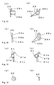
- Figs. 11 and 12 show the configuration of the hook member 23 and the configuration of the presser member 25, respectively, both forming the gripping portion 5 of the left gripper unit 3.
- Fig. 11(a) and Fig. 12(a) show the configurations when viewed from top, respectively.
- Fig. 11(b) and Fig. 12(b) show the configurations when viewed from front, respectively.
- Fig. 11(c) and Fig. 12(c) show the configurations when viewed from right side, respectively.
- the hook member 23 has a hook 23a formed at a lower end thereof, a spring peg 23b formed in an intermediate portion thereof on the side near the top, and a connecting portion 23c formed on the left side.
- the hook 23a is formed by bending a metal sheet shaped as shown in Fig. 1(d) , having for example a width W of 2.6mm and a gap D of 0.6mm. A left side of the yarn presser 25a at the lower end of the presser member 25 is moved into the gap. A part of the front end portion of the yarn presser 25a, which has a thickness T shown in Fig. 12(b) , is moved into the gap D. The part having the thickness T is divided into two parts, between which a space S is defined. The hook 23a having the width W is partly inserted in the space S. The thickness T is 0.8mm and the space S of the yarn presser 25a is 2.4mm.
- the yarn presser 25a spreads out a narrowed portion of the hook 23a resiliently, so that the hook 23a and the yarn presser 25a are put in the state of being held to each other.
- the knitting yarn is gripped between an upper surface of the hook 23a and a lower end of the yarn presser 25a.
- the presser member 25 is provided, at an upper end thereof, with a spring peg 25b.
- the tensile spring 22 shown in Fig. 2 is extended between the spring pegs 23b, 25b of the hook member 23 and the presser member 25.
- the presser member 25 is also provided with an upper lug 25c and a lower lug 25d which are respectively abutted with the upper stopper 11a and the lower stopper 11b of the stop member 11 shown in Fig. 5 , to stop downward movement of the presser member 25.
- the hook member 24 and the presser member 26, which form the griping portion 6 of the right gripper unit 4, have the structure basically symmetrical with the hook member 23 and the presser member 25 of Figs. 11 and 12 . It should be noted however that in the presser member 26, only an upper lug, which corresponds to the upper lug 25c of the presser member 25, is arranged in a position deviated downwardly from the symmetrical position. Since both the upper stopper 11a on the stop member 11 of the left gripper unit 3 and the upper stopper 12a on the stop member 12 of the right gripper unit 4 project in a direction in which they come close to each other, their positions are vertically shifted from each other, in order to avoid interference. This is because the position at which the corresponding upper lug is arranged is deviated.
- Figs. 13, 14, 15 and 16 show the configuration of the movable blade member 28, that of the fixed blade member 29, that of the switch lever 21, and that of the eccentric collar 30, respectively.
- (a) and (b) of the respective drawing figures show the configurations when viewed from front and right side, respectively.
- the movable blade member 28 and the fixed blade member 29 are closed at their blade edges 28a, 29b, the knitting yarn can be cut.
- the movable blade member 28 and the fixed blade member 29 are opened or closed by pivoting about pivot points of center bosses 28b, 29b.
- the movable blade member 28 is provided, at an upper end thereof, with a driving recess 28c.
- the fixed blade member 29 is provided, at an upper end thereof, with a fixing hole 29c for fixing with a screw.
- the switch lever 21 shown in Fig. 15 has, at a top end thereof, an abutting portion 21a with which two abutment lugs 16c, 16d of the link driving member 16 shown in Fig. 9 can be brought into abutment.
- the switch lever 21 pivots about a pivot point of a center boss 21b.
- the switch lever 21 is provided, at its lower end, with a working portion 21c, which is in engagement with the driving recess 28c of the movable blade member 28.
- the turning of the drive shaft 8 drives the movable blade member 28 of the cutter 9 to be opened or closed via the abutment lugs 16c, 16d and the switch lever 21.
- the eccentric collars 30 are used for adjusting vertical positions of the hook member 23, 24 joined to the link linkage members 13, 14.
- Figs. 17-20 schematically show the process of catching and cutting the knitting yarn in a single operation during which the left gripper unit 3 and the right gripper unit 4 are moved close to each other, as shown in Fig. 1 , and the drive shafts 7, 8 are angularly shifted in one direction and then angularly shifted in the opposite direction to be returned therefrom.
- (a) and (b) of those drawing figures show the configurations when viewed from front and right side of the left gripper unit 3, respectively.
- the two abutment lugs 16c, 16d of the link driving member 16 are provided on the right gripper unit 4, since they drive the opening or closing movement of the cutter 9, the right gripper unit 4 is shown in parallel with the left gripper unit 3.
- needle bed of the needle beds 40 which are arranged opposite to each other across the needle bed gap 2
- like needle bed is also arranged on the front side and a number of knitting needles are also arranged in parallel along that needle bed.
- a movable sinker 42 may be arranged between the knitting needles 41.
- the knitting needle 41 and the movable sinker 42 are advanced to or retracted from the needle bed gap 2 and supplied with the knitting yarn from a yarn feeder portion 43 arranged at the lower end of the yarn feeding member such as the yarn feeder, for the knitting of the knitted fabric.
- the needle bed is slanted in such a manner that as it comes closer to the needle bed gap 2, it goes higher in level, while as it moves away therefrom, it goes lower in level.
- Fig. 17 shows a reference state in which the gripping portions 5, 6 are on standby over the needle bed gap 2.
- the gripping portions 5, 6 and the cutter 9 are both closed.
- the link driving members 15, 16 are driven and also the link driven member 17 is driven.
- the link linkage members 13, 14 begin to move downwards.
- the hook members 23, 24 are joined to the link linkage members 13, 14, respectively, the hook members 23, 24 are also moved downwards.
- the presser members 25, 26 are also pulled by and moved downwards by those hook members 23, 24 through the tension spring 22.
- Fig. 18 shows the state in which the upper lugs 25c, 26c of the presser members 25, 26 are abutted with the upper stoppers 12a, 11a of the stop members 12, 11, so that the downward movement of the presser members 25, 26 is brought to a step.
- the movable blade member 28 begins to open through the driving recess 28c of the movable blade member 28 in which the working portion 21c of the switch lever 21 is engaged.
- Fig. 19 shows the state in which the hooks 23a, 23b of the gripping portions 5, 6 which are in the opened state are moved into the needle bed gap 2.
- the movable blade member 28 is in the fully opened state.
- Fig. 20 shows the state in which the drive shafts 7, 8 are on the way of being angularly shifted in the clockwise direction to be returned to the reference condition.
- the movable blade member 28 When the other abutment lug 16d of the link driving member 16 is abutted with the abutting portion 21a of the switch lever 21, the movable blade member 28 begins to close through the driving recess 28c of the movable blade member 28 in which the working portion 21c of the switch lever 21 is engaged. Since the angle of the drive shaft 8 at which the movable blade member 28 begins to open is different from the angle of the drive shaft 8 at which the moveable blade member 28 begins to close, the cutter 9 can be opened or closed at an appropriate timing.
- Figs. 21 and 22 show the unilateral operation of the gripping portion 5 of the left gripper unit 3.
- (a) and (b) of the respective drawing figures show the configurations when viewed from front and right side of the left gripper unit 3, respectively.
- the presser member 25 moves down together with the hook member 23 until the lower lug 25d of the presser member 25 abuts with the lower stopper 11b of the stop member 11.
- the hook 23a can be moved into the needle bed gap 2 in the state in which the gripping portion 5 is slightly opened so that a yarn gripping force is decreased.
- this unilateral operation can be used for treating the edge yarn produced by the cutting of the knitting yarn.
- the same unilateral operation may be performed in the right gripper unit 4.
- the cutter 9 is never opened or closed to cut the knitting yarn, so long as the left gripper unit 3 and the right gripper unit 4 are moved closer to each other, as shown in Fig. 1 . Hence, there is little fear that the knitting yarn may be cut by malfunction in the unilateral operation.
- the edge yarn treatment device 1 is modified so that the link driving member 15 of the left gripper unit 3 is provided with equivalent to the abutment lugs 16c, 16d for driving the cutter, the gripping portion 5 and the cutter 9 on the side of the left gripper unit 3 can be simultaneously operated by the turning of the drive shaft 7.
- the knitting yarn extending from the knitted fabric to yarn feeding member can be cut and gripped, in common with the knitting yarn gripping and cutting device disclosed by Patent Citation 2.
Landscapes
- Engineering & Computer Science (AREA)
- Textile Engineering (AREA)
- Knitting Machines (AREA)
- Braiding, Manufacturing Of Bobbin-Net Or Lace, And Manufacturing Of Nets By Knotting (AREA)
Description
- The present invention relates to an edge yarn treatment device for a flatbed knitting machine, which is capable of catching a knitting yarn extending from a knitting needle to a yarn feeder, to hold or cut it when a knitted fabric is knitted by a flatbed knitting machine, and in particular to an edge yarn treatment device according to the preamble of
claim 1 and as known fromEP1666653 . - In general, an edge yarn treatment device which is capable of catching a knitting yarn extending from a knitting needle to a yarn feeder to hold or cut it is combined in the flatbed knitting machine (See Patent Citation 1, for example).
Patent Citation 1 discloses two separately movable gripper units, one of which is provided with a scissor-like cutter and is driven by turning of a drive shaft which works as a track in guiding the movement. A cam mechanism is formed between the both gripper units, for driving the cutter. The cam mechanism is actuated along the direction along which the track shaft extends. The knitting yarn is cut with the cutter when it is in the state of being gripped by each of the two grippers. An edge yarn resulting from the cutting of the knitting yarn can be treated in the same manner as illustrated inFig. 20 ofPatent Citation 1. - Another edge yarn cutting and gripping device is also disclosed which is structured so that the scissor-like cutter is driven together with the gripper by the turning of the drive shaft to guide the gripper unit (See
Patent Citation 2, for example). The device disclosed by Patent Citation 2 is structured so that when the drive shaft is shifted angularly in one direction and returned from the reference angle, the gripper can be moved down into a needle bed gap to catch and grip the knitting yarn extending from the knitted fabric to the yarn feeder at some midpoint in it. In the middle of the downward movement of the griper into the needle bed gap, the scissor-like cutter is opened and is held in its opened state even after the gripper is moved up, so that the knitting yarn is pulled up in the opened cutter. When the drive shaft is shifted angularly in the opposite direction and returned from the reference angle, only the cutter is closed, so that the knitting yarn gripped by the gripper is cut with the cutter on the side near the knitted fabric. - Patent Citation 1: Japanese Unexamined Patent Publication No.
2005-89933 - Patent Citation 2: Japanese Unexamined Patent Publication No.
Hei 8-325901 -
Patent Citation 2 discloses a structure of the flatbed knitting machine for knitting right and left gloves simultaneously, using two knitting yarn cut and grip devices for doing the treatment of the edge yarns of fingers of the gloves, while doing the set up. However, each of the knitting yarn cut and grip devices merely has the function of cutting the knitting yarn and gripping it on the yarn feeder side until the next set up. After the cutting, the edge yarn on the knitted fabric side is released from the gripper, so that the treatment as is illustrated inFig. 20 ofPatent Citation 1 cannot be done. Also, although the knitting yarn is caught and gripped in the state of being able to be cut with the cutter in the way that the drive shaft is shifted angularly in one direction and returned from the reference angle to move the grippers up and down, the drive shaft must be shifted angularly in the opposite direction from the reference angle, for cutting the knitting yarn with the cutter. This means that two steps of the one reciprocating motion of the drive shaft in one direction from the reference angle and another reciprocating motion of the same in the opposite direction therefrom are necessary for the turning of the drive shaft to drive the gripper and the cutter so as to grip and cut the knitting yarn, where the reciprocating angular displacement of the drive shaft is taken as a single step. - The edge yarn treatment of Patent Citation 1 requires that the cam mechanism be driven along the direction along which the drive shaft extends, in order to actuate the cutter. Thus, this edge yarn treatment requires two steps of driving the gripper by the turning of the drive shaft and driving the cam mechanism along the drive shaft, thus involving complicated control and long operating time. In addition, when the cam mechanism is driven along the drive shaft to actuate the cutter, the gripper units must be stably held with respect to the drive shaft. For stability of the fixed position of the gripper units, the gripper units are required to have a somewhat increased resistance to slippage when moved along the drive shaft. As the resistance to slippage increases, the gripper units decrease in movement speed when being moved along the drive shaft and resultantly a motor as a driving source for the movement is also increased in size.
- It is an object of the present invention to provide an edge yarn treatment device for a flatbed knitting machine which is capable of driving two grippers and a cutter to grip and cut a knitting yarn in a single operation of turning of the drive shaft.
- The present invention provides an edge yarn treatment device for a flatbed knitting machine, which provided with:
- a pair of units, each having grippers which are separately movable over a needle bed gap of the flatbed knitting machine and are advanced to or retracted from the needle bed gap to catch and grip a knitting yarn, and
- a pair of drive shafts extended over the needle bed gap, the drive shafts being able to respectively drive the units in a manner so as to move the grippers toward or away from the needle bed gap by turning of the drive shafts,
- one of the units being provided with a scissor-like cutter capable of cutting the knitting yarn gripped between both of the grippers,
- the edge yarn treatment device further comprising a switching mechanism which is driven by one of the drive shafts in such an associated relationship that when the grippers of the unit driven by the drive shaft are on the way of moving toward the needle bed gap, the cutter can be opened, while on the other hand, when they are on the way of moving away therefrom, the cutter can be closed, so as to switch opening or closing movement of the cutter.
- In the present invention, said switching mechanism comprises:
- a driving member mounted on said one drive shaft and having two abutment lugs projecting at spaced points, and
- a switching member which is mounted on said unit mounting the cutter thereon and is disposed in such a position that when the drive shaft mounting the driving member thereon is turned, the switching member can be alternately abutted with two abutment lugs to selectively open or close the cutter by abutment with one or the other of the abutment lugs.
- In the present invention, said driving member is mounted on a different unit from said unit mounting the cutter thereon and is driven in a combined manner by the drive shaft for driving the grippers in that unit.
- According to the present invention, a pair of units, each having grippers, are separately movable over the needle bed of the flatbed knitting machine. The grippers are moved toward or away from the needle bed gap by turning of the drive shafts. One of the units is provided with the scissor-like cutter. The switching mechanism may be driven by one of the drive shafts in such an associated relationship that when the grippers of the unit driven by the drive shaft are on the way of moving toward the needle bed gap, the cutter can be opened, while on the other hand, when they are on the way of moving away therefrom, the cutter can be closed. The other gripper can be moved toward the needle bed gap by turning of the other drive shaft. Thus, the two grippers and the cutter can be driven for the gripping and the cutting of the knitting yarn in a single operation of the turning of both of the driving shafts. The drive shaft for driving the cutter may be separate from the drive shaft for driving the grippers of the unit mounting the cutter thereon, to carry out the gripping of the knitting yarn with the grippers and the cutting of the knitting yarn with the cutter separately. The drive shaft for driving the cutter may be common with the drive shaft for driving the grippers of the unit mounting the cutter thereon, to carry out the gripping of the knitting yarn with those grippers only and the cutting of the knitting yarn continuously.
- According to the present invention, since the two abutment lugs on the driving member are spaced from each other, an angle of the drive shaft at which the cutter begins to be opened when the grippers are moved toward the needle bed gap and an angle of the drive shaft at which the cutter begins to be closed when the grippers are moved away from the needle bed gap can be varied with each other. This varied angle can provide a preferred timing in opening or closing the cutter even when the turning of the drive shafts is carried out in a single operation.
- According to the present invention, the driving member of the switching mechanism for switching the opening or closing movement of the cutter and the switching lever are provided in two separate units, respectively. The opening or closing movement of the cutter cannot be switched until the two separate units are moved close to each other to an extent that the abutment lugs of the driving member are nearly abutted with the switching member. Accordingly, although the grippers and the cutter can be driven in a single operation of the turning of the single drive shaft, only the grippers may also be driven when the two units are separated from each other.
-
- [
Fig.1] Fig. 1 is a front view simplistically showing a schematic configuration of an edgeyarn treatment device 10 for a flatbed knitting machine of a certain embodiment of the present invention. - [
Fig.2] Figs. 2 are a plan view, a front view and a right side view showing the configuration of aleft gripper unit 3 ofFig. 1 . - [
Fig.3] Figs. 3 are a plan view, a left side view and a front view showing the configuration of aright gripper unit 4 ofFig. 1 . - [
Fig.4] Figs. 4 are a plan view, a front view and a right side view showing the configuration of abase member 10 ofFig. 1 . - [
Fig.5] Figs. 5 are a plan view, a front view and a right side view showing the configuration of astop member 11 ofFig. 1 . - [
Fig.6] Figs. 6 are a plan view, a left side view and a front view showing the configuration of astop member 12 ofFig. 1 . - [
Fig.7] Figs. 7 are a left side view and a front view showing the configuration of alink linkage member 13 ofFig. 1 . - [
Fig.8] Figs. 8 are a front view and a right side view showing the configuration of alink driving member 15 ofFig. 1 . - [
Fig.9] Figs. 9 are a front view and a right side view showing the configuration of alink driving member 1 ofFig. 1 . - [
Fig.10] Figs. 10 are a front view and a right side view showing the configuration of a link drivenmember 17 ofFig. 1 . - [
Fig.11] Figs. 11 are a plan view, a front view, a right side view showing the configuration of ahook member 23 ofFig. 2 , and an enlarged view of the same in the vicinity of the tip end. - [
Fig.12] Figs. 12 are a plan view, a front view, and a right side view showing the configuration of apresser member 25 ofFig. 2 . - [
Fig.13] Figs. 13 are a front view and a right side view showing the configuration of amovable blade member 28 ofFig. 2 . - [
Fig.14] Figs. 14 are a front view and a right side view showing the configuration of astationary blade member 29 ofFig. 2 . - [
Fig.15] Figs. 15 are a front view and a right side view showing the configuration of a switchinglever 21 ofFig. 2 . - [
Fig.16] Figs. 16 are a front view and a right side view showing the configuration of aneccentric collar 30 ofFigs. 2 and3 , - [
Fig.17] Figs. 17 are a simplified front view and a simplified right side view showing the state in which the edgeyarn treatment device 1 ofFig. 1 is on standby at a reference position. - [
Fig.18] Figs. 18 are a simplified front view and a simplified right side view showing the state in which the edgeyarn treatment device 1 ofFig. 1 starts operation for gripping the knitting yarn and begins to open thecutter 9. - [
Fig.19] Figs. 19 are a simplified front view and a simplified right side view showing the state in which the edgeyarn treatment device 1 ofFig. 1 drives gripping portions needle bed gap 2. - [
Fig.20] Figs. 20 are a simplified front view and a simplified right side view showing the state in which theleft gripper unit 3 ofFig. 1 drives thegripping portions needle bed gap 2 so as to grip the knitting yarn and then drives the gripping portions to move upward, on the way of which thecutter 9 begins to be closed. - [
Fig.21] Figs. 21 are a simplified front view and a simplified right side view showing the state in which a hook 23a and a yarn presser 25a begin to be in an open state on the way of the unilateral operation in which theleft gripper unit 3 ofFig. 1 drives the grippingportion 5 to move into theneedle bed gap 2, - [
Fig.22] Figs. 22 are a simplified front view and a simplified right side view showing the state in which the hook 23a and the yarn presser 25a are put in an open state and the hook 23a is moved into theneedle bed gap 2 on the way of the unilateral operation in which theleft gripper unit 3 ofFig. 1 drives the grippingportion 5 to move into theneedle bed gap 2. -
- 1
- Edge yarn treatment device
- 2
- Needle bed gap
- 3
- Left gripper unit
- 4
- Right gripper unit
- 5, 6
- Gripping portion
- 7, 8
- Drive shaft
- 9
- Cutter
- 10
- Base member
- 11, 12
- Stop member
- 13, 14
- Link linkage member
- 15, 16
- Link driving member
- 17
- Link driven member
- 20
- Track member
- 21
- Switch member
- 23, 24
- Hook member
- 25, 26
- Presser member
- 28
- Movable blade member
- 29
- Fixed blade member
-
Fig. 1 simplistically shows a schematic configuration of an edgeyarn treatment device 1 of a certain embodiment of the present invention. In the flatbed knitting machine including the edgeyarn treatment device 1, a knitting yarn is fed from a yarn feeding member such as a yarn feeder to knitting needles movable into aneedle bed gap 2 across which front and back needle beds are arranged opposite to each other, to knit a knitted fabric with the knitting needles. A number of knitting needles are arranged in parallel in each of the needle beds. A carriage is moved in reciprocation along the needle beds together with the yarn feeding member, while driving the knitting needles selectively, to knit the knitted fabric. The yarn feeding member runs along a yarn guide extended over theneedle bed gap 2. After completion of the knitting of a finger of a glove, the knitting yarn is put in the state of extending between the knitting needle at which the knitting is ended and the yarn feeding member immediately before the start to knit the next finger of the glove. - The edge
yarn treatment device 1 is used for treating the edge yarn produced when the knitting yarn extending in this state is caught and cut. The edgeyarn treatment device 1 includes two gripper units of aleft gripper unit 3 and aright gripper unit 4. Theleft gripper unit 3 and theright gripper unit 4 havegripping portions left gripper unit 3 and theright gripper unit 4 are supported by twodrive shafts needle bed gap 2 so that they can be moved laterally in a sliding manner. Thegripping portions drive shafts left gripper unit 3 and theright gripper unit 4 are basically common to each other in motion and configuration on at least thegripping portions left gripper unit 3 is provided with a scissor-like cutter 9. The grippingportion 5 of theleft gripper unit 3 is moved by the turning of thedrive shaft 7, while on the other hand, thecutter 9 is driven to be opened or closed by turning of thedrive shaft 8 for driving the grippingportion 6 of theright gripper unit 4 to move. - The
left gripper unit 3 and theright gripper unit 4 support their respective components viabase members 10. Thebase members 10 are common to each other for the left and right gripper units. Theleft gripper unit 3 has thegripping portion 5 formed at the right side of thebase member 10, and theright gripper unit 4 has thegripping portion 6 formed at the left side of thebase member 10. Aleft stop member 11 and aright stop member 12 are mounted on thebase member 10 of theleft gripper unit 3 and thebase member 10 of theright gripper unit 4, respectively. - The
gripping portions drive shafts drive shafts link linkage members link linkage member 13 located on the side of theleft gripper unit 3 has a driving linkage shaft 13a and a driven linkage shaft 13b extending leftwards. Alink driving member 15 is provided between the driving linkage shaft 13a and thedrive shaft 7. Thelink linkage member 14 on the side of theright gripper unit 4 has a driving linkage shaft 14a and a driven linkage shaft 14b which extend rightwards. Alink driving member 16 is provided between the driving linkage shaft 14a and thedrive shaft 8. A drivenlink member 17 is provided between the driven linkage member 13b, 14b of thelink linkage member drive shaft left gripper unit 3 and theright gripper unit 4 are moved along the direction along which thedrive shafts base members 10 frommovable racks 19 through movingmembers 18. - A
track member 20 accommodating themovable racks 19 is provided at the back side of thebase member 10. Thetrack member 20 is placed over theneedle bed gap 2 to extend in parallel with thedrive shafts movable racks 19 are formed of synthetic resin and the like having flexibility and have rack teeth engageable with teeth on the movingmembers 18. Themovable racks 19 are extended from both lateral sides of thetrack member 20 and are provided, at front ends thereof, with the movingmembers 18. The right and left movingmembers 19 are separately pushed into accommodation grooves in thetrack member 20 from lateral sides thereof, not shown, or pulled back therefrom. Theleft gripper unit 3 and theright gripper unit 4 can be separately moved in a transverse direction by the drives of themovable racks 19 to such an extent that they do not collide with each other. The right and leftmovable racks 19 have at least a length corresponding to a width of the needle beds so that theleft gripper unit 3 and theright gripper unit 4 can be moved in reciprocation within an extent corresponding to the dimension of the needle beds. When theleft gripper unit 3 or theright gripper unit 4 is placed at a location in the range from the end of the needle bed on the drive side to the opposite end of the same, the end of themovable rack 19 on the drive side runs off the edge of thetrack member 20 on the drive side. Themovable rack 19 running off the edge of thetrack member 20 is guided in a manner so as to be folded in a thickness direction. In substitution for thetrack member 20, thedrive shafts left gripper unit 3 and theright gripper unit 4. The provision of the track like thetrack member 20 can provide decrease in resistance to slippage of thedrive shafts shafts -
Fig. 2 andFig. 3 show the configuration of theleft gripper unit 3 and the configuration of theright griper unit 4, respectively.Fig. 2(a), Fig. 2(b), and Fig. 2(c) show the configurations when viewed from top, front, and right side, respectively.Fig. 3(a), Fig. 3(b), and Fig. 3(c) show the configurations when viewed from top, left side, and front, respectively. It is to be added however that inFigs. 2 and3 and in other drawing figures, some parts described are omitted in the drawings viewed in a different orientation and viewed from other direction, while on the other hand, some parts omitted are illustrated in the drawings viewed in a different orientation, for avoiding troublesomeness. - The
left gripper unit 3 is provided with aswitch lever 21 as a switch member to switch in a manner so as to open or close thecutter 9. Theswitch lever 21 is pivotally displaced by abutment of its upper end with a lug provided on the left end of thelink driving member 16 on the side of theright gripper unit 4 to switch opening or closing movement of thecutter 9 at the lower end thereof. - The
gripping portions left gripper unit 3 and theright gripper unit 4 are formed by thehook members presser members presser members hook members - The
cutter 9 includes amovable blade member 28 pressed by acompressed spring 27 and a fixedblade member 29. Themovable blade member 28 is driven to be opened or closed by theswitch member 21. Thehook members link linkage members eccentric collar 30 is screwed at an intermediate position between the two vertically spaced points. -
Fig. 4 shows the configuration of thebase member 10.Fig. 4(a), Fig. 4(b), and Fig. 4(c) show the configurations when viewed from top, front, and right side, respectively. Thebase member 10 is provided, at a right side thereof, with a left gripper accommodating portion 10a, and is provided, at a left side thereof, with a right gripper accommodating portion 10b. Thebase member 10 can be commonly used for theleft gripper unit 3 and theright gripper unit 4 so that any one of the right and left gripper units can be incorporated in the base member. Thelink driving members member 17 are incorporated in the base member in a manner so as to extend across the area of both of the left gripper accommodating portion 10a and the right gripper accommodating portion 10b. Thebase member 10 has, at its upper portion, a moving member fitting portion 10c formed to fit the movingmember 18 therein so as to connect to the front end of the movable rack shown inFigs. 2 and3 . Thebase member 10 has, at a center portion thereof, a wall projecting forwardly to draw a border with respect to a transverse direction. Drive shaft insertion holes 10d, 10e for thedrive shafts track member 20 shown inFigs. 1 ,2 and3 are provided at the back side of thebase member 10. -
Figs. 5 and6 show the configuration of thestop members left gripper unit 3 and theright gripper unit 4.Fig. 5(a), Fig. 5(b), and Fig. 5(c) show the configurations when viewed from top, front, and right side, respectively.Fig. 6(a), Fig. 6(b), and Fig. 6(c) show the configurations when viewed from top, left side, and front, respectively. Thestop members stop member 11 to be mounted in theleft gripper unit 3 is provided with a cutter mounting portion 11c. -
Fig. 7 shows the configuration of thelink linkage member 13 in theleft gripper unit 3.Fig. 7(a) and Fig. 7(b) show the configurations when viewed from left side and front, respectively. Thelink linkage member 14 in theright gripper unit 4 is basically symmetrical with thelink linkage member 13. It is noted however that in thelink linkage member 13, the drive connection shaft 13a is located at the lower side, and the driven connection shaft 13b is located at the upper side. On the other hand, in thelink linkage member 14, the drive connection shaft 14a is located at the upper side and the driven connection shaft 14b is located at the lower side. No structural difference exists between the driving connection shafts 13a, 14a and the driven connection shafts 13b, 14b. Thelink linkage member 13 is provided, around its central portion, with a connecting portion 13c, to which thehook member 23 and theeccentric collar 30 are screwed. Thelink linkage member 14 is arranged in common with thelink linkage member 13. -
Figs. 8, 9, 10 show the configuration of thelink driving members member 17, respectively.Fig. 8(a) and Fig. 8(b) show the configurations when viewed from front and right side, respectively.Fig. 9(a) and Fig. 9(b) show the configurations when viewed from left side and front, respectively.Fig. 10(a) and Fig. 10(b) show the configurations when viewed from front and right side, respectively. Thelink driving members member 17 are respectively provided with drive shaft insertion holes 15a, 16a, 17a for thedrive shafts link linkage member drive shafts link driving members drive shafts - The
link driving member 16 used in theright gripper unit 4 shown inFig. 9 has two abutment lugs 16c, 16d at its left end on the side confronting the leftgripping unit 3. Thelink driving member 16 functions as a drive member for thecutter 9 of theleft gripper unit 3 to be opened or closed by the turning of thedrive shaft 8 which drives the grippingportion 6 of theright gripper unit 4 open or close, when theleft gripper unit 3 and theright gripper unit 4 are connected to each other as shown inFig. 1 . -
Figs. 11 and12 show the configuration of thehook member 23 and the configuration of thepresser member 25, respectively, both forming thegripping portion 5 of theleft gripper unit 3.Fig. 11(a) andFig. 12(a) show the configurations when viewed from top, respectively.Fig. 11(b) andFig. 12(b) show the configurations when viewed from front, respectively.Fig. 11(c) andFig. 12(c) show the configurations when viewed from right side, respectively. Thehook member 23 has a hook 23a formed at a lower end thereof, a spring peg 23b formed in an intermediate portion thereof on the side near the top, and a connecting portion 23c formed on the left side. The hook 23a is formed by bending a metal sheet shaped as shown inFig. 1(d) , having for example a width W of 2.6mm and a gap D of 0.6mm. A left side of the yarn presser 25a at the lower end of thepresser member 25 is moved into the gap. A part of the front end portion of the yarn presser 25a, which has a thickness T shown inFig. 12(b) , is moved into the gap D. The part having the thickness T is divided into two parts, between which a space S is defined. The hook 23a having the width W is partly inserted in the space S. The thickness T is 0.8mm and the space S of the yarn presser 25a is 2.4mm. Thus, when being moved into the hook 23a, the yarn presser 25a spreads out a narrowed portion of the hook 23a resiliently, so that the hook 23a and the yarn presser 25a are put in the state of being held to each other. In thegripping portion 5, the knitting yarn is gripped between an upper surface of the hook 23a and a lower end of the yarn presser 25a. Thepresser member 25 is provided, at an upper end thereof, with a spring peg 25b. Thetensile spring 22 shown inFig. 2 is extended between the spring pegs 23b, 25b of thehook member 23 and thepresser member 25. Thepresser member 25 is also provided with an upper lug 25c and a lower lug 25d which are respectively abutted with the upper stopper 11a and the lower stopper 11b of thestop member 11 shown inFig. 5 , to stop downward movement of thepresser member 25. - The
hook member 24 and thepresser member 26, which form the gripingportion 6 of theright gripper unit 4, have the structure basically symmetrical with thehook member 23 and thepresser member 25 ofFigs. 11 and12 . It should be noted however that in thepresser member 26, only an upper lug, which corresponds to the upper lug 25c of thepresser member 25, is arranged in a position deviated downwardly from the symmetrical position. Since both the upper stopper 11a on thestop member 11 of theleft gripper unit 3 and the upper stopper 12a on thestop member 12 of theright gripper unit 4 project in a direction in which they come close to each other, their positions are vertically shifted from each other, in order to avoid interference. This is because the position at which the corresponding upper lug is arranged is deviated. -
Figs. 13, 14, 15 and 16 show the configuration of themovable blade member 28, that of the fixedblade member 29, that of theswitch lever 21, and that of theeccentric collar 30, respectively. (a) and (b) of the respective drawing figures show the configurations when viewed from front and right side, respectively. When themovable blade member 28 and the fixedblade member 29 are closed at their blade edges 28a, 29b, the knitting yarn can be cut. Themovable blade member 28 and the fixedblade member 29 are opened or closed by pivoting about pivot points of center bosses 28b, 29b. Themovable blade member 28 is provided, at an upper end thereof, with a driving recess 28c. The fixedblade member 29 is provided, at an upper end thereof, with a fixing hole 29c for fixing with a screw. Theswitch lever 21 shown inFig. 15 has, at a top end thereof, an abutting portion 21a with which two abutment lugs 16c, 16d of thelink driving member 16 shown inFig. 9 can be brought into abutment. When the abutment lugs 16c, 16d abut with the abutting portion 21a, theswitch lever 21 pivots about a pivot point of a center boss 21b. Theswitch lever 21 is provided, at its lower end, with a working portion 21c, which is in engagement with the driving recess 28c of themovable blade member 28. The turning of thedrive shaft 8 drives themovable blade member 28 of thecutter 9 to be opened or closed via the abutment lugs 16c, 16d and theswitch lever 21. Theeccentric collars 30 are used for adjusting vertical positions of thehook member link linkage members -
Figs. 17-20 schematically show the process of catching and cutting the knitting yarn in a single operation during which theleft gripper unit 3 and theright gripper unit 4 are moved close to each other, as shown inFig. 1 , and thedrive shafts left gripper unit 3, respectively. Although the two abutment lugs 16c, 16d of thelink driving member 16 are provided on theright gripper unit 4, since they drive the opening or closing movement of thecutter 9, theright gripper unit 4 is shown in parallel with theleft gripper unit 3. - Although only the back needle bed of the
needle beds 40 which are arranged opposite to each other across theneedle bed gap 2 is simplistically shown, like needle bed is also arranged on the front side and a number of knitting needles are also arranged in parallel along that needle bed. Amovable sinker 42 may be arranged between the knitting needles 41. The knitting needle 41 and themovable sinker 42 are advanced to or retracted from theneedle bed gap 2 and supplied with the knitting yarn from ayarn feeder portion 43 arranged at the lower end of the yarn feeding member such as the yarn feeder, for the knitting of the knitted fabric. The needle bed is slanted in such a manner that as it comes closer to theneedle bed gap 2, it goes higher in level, while as it moves away therefrom, it goes lower in level. Due to this, when theneedle bed 40 is presented on paper as being on the level, a vertical center line 2a in theneedle bed gap 2 is slanted on that paper. Since the yarn guide rail along which the yarn feeding member such as the yarn feeder moves is disposed over theneedle bed gap 2, theleft gripper unit 3 and theright gripper unit 4 disposed are deviated from directly over theneedle bed gap 2 toward theback needle bed 40. Since thegripping portions portions needle bed gap 2 in a roundabout manner even from a slightly deviated position. -
Fig. 17 shows a reference state in which thegripping portions needle bed gap 2. Thegripping portions cutter 9 are both closed. When thedrive shafts link driving members member 17 is driven. As a result of this, thelink linkage members hook members link linkage members hook members presser members hook members tension spring 22. -
Fig. 18 shows the state in which the upper lugs 25c, 26c of thepresser members stop members presser members link driving member 16 abuts with the abutting portion 21a of theswitch lever 21, themovable blade member 28 begins to open through the driving recess 28c of themovable blade member 28 in which the working portion 21c of theswitch lever 21 is engaged. -
Fig. 19 shows the state in which the hooks 23a, 23b of thegripping portions needle bed gap 2. Themovable blade member 28 is in the fully opened state. -
Fig. 20 shows the state in which thedrive shafts hook members portions portions hook members presser members presser members hook members link driving member 16 is abutted with the abutting portion 21a of theswitch lever 21, themovable blade member 28 begins to close through the driving recess 28c of themovable blade member 28 in which the working portion 21c of theswitch lever 21 is engaged. Since the angle of thedrive shaft 8 at which themovable blade member 28 begins to open is different from the angle of thedrive shaft 8 at which themoveable blade member 28 begins to close, thecutter 9 can be opened or closed at an appropriate timing. -
Figs. 21 and22 show the unilateral operation of thegripping portion 5 of theleft gripper unit 3. (a) and (b) of the respective drawing figures show the configurations when viewed from front and right side of theleft gripper unit 3, respectively. As shown inFig. 21 , in the unilateral operation, thepresser member 25 moves down together with thehook member 23 until the lower lug 25d of thepresser member 25 abuts with the lower stopper 11b of thestop member 11. When thehook member 23 is further moved down, the hook 23a can be moved into theneedle bed gap 2 in the state in which thegripping portion 5 is slightly opened so that a yarn gripping force is decreased. As illustrated inFig. 20 ofPatent Citation 1, this unilateral operation can be used for treating the edge yarn produced by the cutting of the knitting yarn. The same unilateral operation may be performed in theright gripper unit 4. - In the edge
yarn treatment device 1 of the illustrated embodiment, thecutter 9 is never opened or closed to cut the knitting yarn, so long as theleft gripper unit 3 and theright gripper unit 4 are moved closer to each other, as shown inFig. 1 . Hence, there is little fear that the knitting yarn may be cut by malfunction in the unilateral operation. When the edgeyarn treatment device 1 is modified so that thelink driving member 15 of theleft gripper unit 3 is provided with equivalent to the abutment lugs 16c, 16d for driving the cutter, the grippingportion 5 and thecutter 9 on the side of theleft gripper unit 3 can be simultaneously operated by the turning of thedrive shaft 7. In this variant, the knitting yarn extending from the knitted fabric to yarn feeding member can be cut and gripped, in common with the knitting yarn gripping and cutting device disclosed byPatent Citation 2.
Claims (3)
- An edge yarn treatment device (1) for a flatbed knitting machine, which is provided with:a pair of units (3, 4), each having grippers which are separately movable over a needle bed gap (2) of the flatbed knitting machine and are advanced to or retracted from the needle bed gap (2) to catch and grip a knitting yarn, anda pair of drive shafts (7, 8) extended over the needle bed gap (2), the drive shafts (7, 8) being able to respectively drive the units (3, 4) in a manner so as to move the grippers toward or away from the needle bed gap (2) by turning of the drive shafts (7, 8),one of the units (3, 4) being provided with a scissor-like cutter (9) capable of cutting the knitting yarn gripped between both of the grippers,characterised in that the edge yarn treatment device (1) further comprises a switching mechanism which is driven by one of the drive shafts (7, 8) in such an associated relationship that when the grippers of the unit driven by the drive shaft are on the way of moving toward the needle bed gap (2), the cutter (9) can be opened, while on the other hand, when they are on the way of moving away therefrom, the cutter (9) can be closed, so as to switch opening or closing movement of the cutter.
- The edge yarn treatment device (1) for the flatbed knitting machine according to Claim 1, wherein said switching mechanism comprises:a driving member (16) mounted on said one drive shaft and having two abutment lugs (16c, 16b) projecting at spaced points, anda switching member which is mounted on said unit mounting the cutter (9) thereon and is disposed in such a position that when the drive shaft mounting the driving member thereon is turned, the switching member can be alternately abutted with two abutment lugs to selectively open or close the cutter by abutment with one or the other of the abutment lugs.
- The edge yarn treatment device for the flatbed knitting machine according to Claim 2, wherein said driving member (16) is mounted on a different unit from said unit mounting the cutter (9) thereon and is driven in a combined manner by the drive shaft for driving the grippers in that unit.
Applications Claiming Priority (2)
| Application Number | Priority Date | Filing Date | Title |
|---|---|---|---|
| JP2007341539 | 2007-12-29 | ||
| PCT/JP2008/003945 WO2009084193A1 (en) | 2007-12-29 | 2008-12-25 | Yarn-end treating device for flat-knitting machine |
Publications (3)
| Publication Number | Publication Date |
|---|---|
| EP2241660A1 EP2241660A1 (en) | 2010-10-20 |
| EP2241660A4 EP2241660A4 (en) | 2013-02-20 |
| EP2241660B1 true EP2241660B1 (en) | 2014-01-01 |
Family
ID=40823929
Family Applications (1)
| Application Number | Title | Priority Date | Filing Date |
|---|---|---|---|
| EP08868426.1A Not-in-force EP2241660B1 (en) | 2007-12-29 | 2008-12-25 | Yarn-end treating device for flat-knitting machine |
Country Status (4)
| Country | Link |
|---|---|
| EP (1) | EP2241660B1 (en) |
| JP (1) | JP5161242B2 (en) |
| CN (1) | CN101910489B (en) |
| WO (1) | WO2009084193A1 (en) |
Cited By (1)
| Publication number | Priority date | Publication date | Assignee | Title |
|---|---|---|---|---|
| EP4332287A1 (en) * | 2022-08-31 | 2024-03-06 | Shima Seiki Mfg., Ltd. | End yarn processing device and end yarn processing method |
Families Citing this family (1)
| Publication number | Priority date | Publication date | Assignee | Title |
|---|---|---|---|---|
| JP2014221958A (en) * | 2013-05-14 | 2014-11-27 | 株式会社島精機製作所 | Apparatus for treating terminal filament in flat-knitting machine |
Family Cites Families (7)
| Publication number | Priority date | Publication date | Assignee | Title |
|---|---|---|---|---|
| JPH08325901A (en) | 1995-05-24 | 1996-12-10 | Shima Seiki Mfg Ltd | Knitting yarn-cutting and-holding device in weft knitting machine |
| CN2274198Y (en) * | 1996-10-26 | 1998-02-11 | 张民 | Cutting device for yarn-broken protector of loom wheel machine |
| DE19844833A1 (en) * | 1998-09-30 | 2000-04-13 | Stoll & Co H | Thread clamping and cutting device for knitting machines |
| JP4015980B2 (en) * | 2003-09-19 | 2007-11-28 | 株式会社島精機製作所 | End yarn processing apparatus and method for flat knitting machine |
| CN2799607Y (en) * | 2005-04-30 | 2006-07-26 | 富胜精密机械(绍兴)有限公司 | Scissors device for yarn cutting of hosiery knitter |
| JP4390748B2 (en) * | 2005-06-23 | 2009-12-24 | グンゼ株式会社 | Knitting method using circular knitting machine and circular knitting machine |
| WO2008081579A1 (en) * | 2006-12-29 | 2008-07-10 | Shima Seiki Mfg., Ltd. | Yarn end treating device for flat knitting machine |
-
2008
- 2008-12-25 CN CN200880122863.9A patent/CN101910489B/en not_active Expired - Fee Related
- 2008-12-25 WO PCT/JP2008/003945 patent/WO2009084193A1/en active Application Filing
- 2008-12-25 EP EP08868426.1A patent/EP2241660B1/en not_active Not-in-force
- 2008-12-25 JP JP2009547892A patent/JP5161242B2/en not_active Expired - Fee Related
Cited By (1)
| Publication number | Priority date | Publication date | Assignee | Title |
|---|---|---|---|---|
| EP4332287A1 (en) * | 2022-08-31 | 2024-03-06 | Shima Seiki Mfg., Ltd. | End yarn processing device and end yarn processing method |
Also Published As
| Publication number | Publication date |
|---|---|
| CN101910489B (en) | 2012-02-08 |
| EP2241660A4 (en) | 2013-02-20 |
| CN101910489A (en) | 2010-12-08 |
| EP2241660A1 (en) | 2010-10-20 |
| WO2009084193A1 (en) | 2009-07-09 |
| JP5161242B2 (en) | 2013-03-13 |
| JPWO2009084193A1 (en) | 2011-05-12 |
Similar Documents
| Publication | Publication Date | Title |
|---|---|---|
| KR100249119B1 (en) | A flat knitting machine having a transferring mechanism | |
| EP1662032B1 (en) | Weft knitting machine with movable yarn guide member | |
| JP3899269B2 (en) | Yarn feeder for flat knitting machine | |
| EP1666653B1 (en) | Device and method for processing end yarn of weft knitting machine | |
| CN101158087B (en) | End-yarn insertion device | |
| JP2008297643A (en) | Yarn feed-switching device in circular knitting machine | |
| JP2016144492A (en) | sewing machine | |
| CN101158086B (en) | End-yarn insertion device | |
| EP2241660B1 (en) | Yarn-end treating device for flat-knitting machine | |
| JP2005042260A (en) | Feed yarn changeover apparatus for circular knitting machine and changeover method | |
| KR20190000966U (en) | Glove knitting machine | |
| EP1010789B1 (en) | End yarn insertion device of flat knitting machine | |
| EP2570535B1 (en) | Flatbed knitting machine provided with compound needle, and slider control method for flatbed knitting machine | |
| JPH02269848A (en) | Yarn cutting and retaining device, yarn retaining device and yarn cutting device in filling knitting machinery | |
| JP2008297662A (en) | Yarn feed-switching device in circular knitting machine | |
| CN210314701U (en) | Knitting yarn holding and cutting device of flat knitting machine | |
| JP5161113B2 (en) | End yarn processing device for flat knitting machine | |
| JPH05239758A (en) | Thread clamping and cutting apparatus for rear or lower thread of embroidering machine | |
| JPH08325901A (en) | Knitting yarn-cutting and-holding device in weft knitting machine | |
| CN218507988U (en) | Weft knitting machine with movable sinker device | |
| CN110644127A (en) | Wire adjusting head |
Legal Events
| Date | Code | Title | Description |
|---|---|---|---|
| PUAI | Public reference made under article 153(3) epc to a published international application that has entered the european phase |
Free format text: ORIGINAL CODE: 0009012 |
|
| 17P | Request for examination filed |
Effective date: 20100729 |
|
| AK | Designated contracting states |
Kind code of ref document: A1 Designated state(s): AT BE BG CH CY CZ DE DK EE ES FI FR GB GR HR HU IE IS IT LI LT LU LV MC MT NL NO PL PT RO SE SI SK TR |
|
| AX | Request for extension of the european patent |
Extension state: AL BA MK RS |
|
| DAX | Request for extension of the european patent (deleted) | ||
| A4 | Supplementary search report drawn up and despatched |
Effective date: 20130118 |
|
| RIC1 | Information provided on ipc code assigned before grant |
Ipc: D04B 15/56 20060101AFI20130114BHEP |
|
| GRAP | Despatch of communication of intention to grant a patent |
Free format text: ORIGINAL CODE: EPIDOSNIGR1 |
|
| INTG | Intention to grant announced |
Effective date: 20130710 |
|
| GRAS | Grant fee paid |
Free format text: ORIGINAL CODE: EPIDOSNIGR3 |
|
| GRAA | (expected) grant |
Free format text: ORIGINAL CODE: 0009210 |
|
| AK | Designated contracting states |
Kind code of ref document: B1 Designated state(s): AT BE BG CH CY CZ DE DK EE ES FI FR GB GR HR HU IE IS IT LI LT LU LV MC MT NL NO PL PT RO SE SI SK TR |
|
| REG | Reference to a national code |
Ref country code: GB Ref legal event code: FG4D |
|
| REG | Reference to a national code |
Ref country code: CH Ref legal event code: EP |
|
| REG | Reference to a national code |
Ref country code: IE Ref legal event code: FG4D |
|
| REG | Reference to a national code |
Ref country code: AT Ref legal event code: REF Ref document number: 647666 Country of ref document: AT Kind code of ref document: T Effective date: 20140215 |
|
| REG | Reference to a national code |
Ref country code: DE Ref legal event code: R096 Ref document number: 602008029685 Country of ref document: DE Effective date: 20140220 |
|
| REG | Reference to a national code |
Ref country code: NL Ref legal event code: VDEP Effective date: 20140101 |
|
| REG | Reference to a national code |
Ref country code: AT Ref legal event code: MK05 Ref document number: 647666 Country of ref document: AT Kind code of ref document: T Effective date: 20140101 |
|
| REG | Reference to a national code |
Ref country code: LT Ref legal event code: MG4D |
|
| PG25 | Lapsed in a contracting state [announced via postgrant information from national office to epo] |
Ref country code: LT Free format text: LAPSE BECAUSE OF FAILURE TO SUBMIT A TRANSLATION OF THE DESCRIPTION OR TO PAY THE FEE WITHIN THE PRESCRIBED TIME-LIMIT Effective date: 20140101 Ref country code: IS Free format text: LAPSE BECAUSE OF FAILURE TO SUBMIT A TRANSLATION OF THE DESCRIPTION OR TO PAY THE FEE WITHIN THE PRESCRIBED TIME-LIMIT Effective date: 20140501 |
|
| PG25 | Lapsed in a contracting state [announced via postgrant information from national office to epo] |
Ref country code: CY Free format text: LAPSE BECAUSE OF FAILURE TO SUBMIT A TRANSLATION OF THE DESCRIPTION OR TO PAY THE FEE WITHIN THE PRESCRIBED TIME-LIMIT Effective date: 20140101 Ref country code: ES Free format text: LAPSE BECAUSE OF FAILURE TO SUBMIT A TRANSLATION OF THE DESCRIPTION OR TO PAY THE FEE WITHIN THE PRESCRIBED TIME-LIMIT Effective date: 20140101 Ref country code: FI Free format text: LAPSE BECAUSE OF FAILURE TO SUBMIT A TRANSLATION OF THE DESCRIPTION OR TO PAY THE FEE WITHIN THE PRESCRIBED TIME-LIMIT Effective date: 20140101 Ref country code: SE Free format text: LAPSE BECAUSE OF FAILURE TO SUBMIT A TRANSLATION OF THE DESCRIPTION OR TO PAY THE FEE WITHIN THE PRESCRIBED TIME-LIMIT Effective date: 20140101 Ref country code: AT Free format text: LAPSE BECAUSE OF FAILURE TO SUBMIT A TRANSLATION OF THE DESCRIPTION OR TO PAY THE FEE WITHIN THE PRESCRIBED TIME-LIMIT Effective date: 20140101 Ref country code: PT Free format text: LAPSE BECAUSE OF FAILURE TO SUBMIT A TRANSLATION OF THE DESCRIPTION OR TO PAY THE FEE WITHIN THE PRESCRIBED TIME-LIMIT Effective date: 20140502 Ref country code: NL Free format text: LAPSE BECAUSE OF FAILURE TO SUBMIT A TRANSLATION OF THE DESCRIPTION OR TO PAY THE FEE WITHIN THE PRESCRIBED TIME-LIMIT Effective date: 20140101 |
|
| PG25 | Lapsed in a contracting state [announced via postgrant information from national office to epo] |
Ref country code: LV Free format text: LAPSE BECAUSE OF FAILURE TO SUBMIT A TRANSLATION OF THE DESCRIPTION OR TO PAY THE FEE WITHIN THE PRESCRIBED TIME-LIMIT Effective date: 20140101 Ref country code: HR Free format text: LAPSE BECAUSE OF FAILURE TO SUBMIT A TRANSLATION OF THE DESCRIPTION OR TO PAY THE FEE WITHIN THE PRESCRIBED TIME-LIMIT Effective date: 20140101 Ref country code: BE Free format text: LAPSE BECAUSE OF FAILURE TO SUBMIT A TRANSLATION OF THE DESCRIPTION OR TO PAY THE FEE WITHIN THE PRESCRIBED TIME-LIMIT Effective date: 20140101 |
|
| REG | Reference to a national code |
Ref country code: DE Ref legal event code: R097 Ref document number: 602008029685 Country of ref document: DE |
|
| PG25 | Lapsed in a contracting state [announced via postgrant information from national office to epo] |
Ref country code: EE Free format text: LAPSE BECAUSE OF FAILURE TO SUBMIT A TRANSLATION OF THE DESCRIPTION OR TO PAY THE FEE WITHIN THE PRESCRIBED TIME-LIMIT Effective date: 20140101 Ref country code: RO Free format text: LAPSE BECAUSE OF FAILURE TO SUBMIT A TRANSLATION OF THE DESCRIPTION OR TO PAY THE FEE WITHIN THE PRESCRIBED TIME-LIMIT Effective date: 20140101 Ref country code: CZ Free format text: LAPSE BECAUSE OF FAILURE TO SUBMIT A TRANSLATION OF THE DESCRIPTION OR TO PAY THE FEE WITHIN THE PRESCRIBED TIME-LIMIT Effective date: 20140101 Ref country code: DK Free format text: LAPSE BECAUSE OF FAILURE TO SUBMIT A TRANSLATION OF THE DESCRIPTION OR TO PAY THE FEE WITHIN THE PRESCRIBED TIME-LIMIT Effective date: 20140101 |
|
| PLBE | No opposition filed within time limit |
Free format text: ORIGINAL CODE: 0009261 |
|
| STAA | Information on the status of an ep patent application or granted ep patent |
Free format text: STATUS: NO OPPOSITION FILED WITHIN TIME LIMIT |
|
| PG25 | Lapsed in a contracting state [announced via postgrant information from national office to epo] |
Ref country code: PL Free format text: LAPSE BECAUSE OF FAILURE TO SUBMIT A TRANSLATION OF THE DESCRIPTION OR TO PAY THE FEE WITHIN THE PRESCRIBED TIME-LIMIT Effective date: 20140101 Ref country code: SK Free format text: LAPSE BECAUSE OF FAILURE TO SUBMIT A TRANSLATION OF THE DESCRIPTION OR TO PAY THE FEE WITHIN THE PRESCRIBED TIME-LIMIT Effective date: 20140101 |
|
| 26N | No opposition filed |
Effective date: 20141002 |
|
| REG | Reference to a national code |
Ref country code: DE Ref legal event code: R097 Ref document number: 602008029685 Country of ref document: DE Effective date: 20141002 |
|
| PG25 | Lapsed in a contracting state [announced via postgrant information from national office to epo] |
Ref country code: SI Free format text: LAPSE BECAUSE OF FAILURE TO SUBMIT A TRANSLATION OF THE DESCRIPTION OR TO PAY THE FEE WITHIN THE PRESCRIBED TIME-LIMIT Effective date: 20140101 |
|
| PG25 | Lapsed in a contracting state [announced via postgrant information from national office to epo] |
Ref country code: LU Free format text: LAPSE BECAUSE OF FAILURE TO SUBMIT A TRANSLATION OF THE DESCRIPTION OR TO PAY THE FEE WITHIN THE PRESCRIBED TIME-LIMIT Effective date: 20141225 |
|
| REG | Reference to a national code |
Ref country code: CH Ref legal event code: PL |
|
| GBPC | Gb: european patent ceased through non-payment of renewal fee |
Effective date: 20141225 |
|
| REG | Reference to a national code |
Ref country code: IE Ref legal event code: MM4A |
|
| REG | Reference to a national code |
Ref country code: FR Ref legal event code: ST Effective date: 20150831 |
|
| PG25 | Lapsed in a contracting state [announced via postgrant information from national office to epo] |
Ref country code: CH Free format text: LAPSE BECAUSE OF NON-PAYMENT OF DUE FEES Effective date: 20141231 Ref country code: GB Free format text: LAPSE BECAUSE OF NON-PAYMENT OF DUE FEES Effective date: 20141225 Ref country code: IE Free format text: LAPSE BECAUSE OF NON-PAYMENT OF DUE FEES Effective date: 20141225 Ref country code: LI Free format text: LAPSE BECAUSE OF NON-PAYMENT OF DUE FEES Effective date: 20141231 |
|
| PG25 | Lapsed in a contracting state [announced via postgrant information from national office to epo] |
Ref country code: FR Free format text: LAPSE BECAUSE OF NON-PAYMENT OF DUE FEES Effective date: 20141231 |
|
| PG25 | Lapsed in a contracting state [announced via postgrant information from national office to epo] |
Ref country code: NO Free format text: LAPSE BECAUSE OF FAILURE TO SUBMIT A TRANSLATION OF THE DESCRIPTION OR TO PAY THE FEE WITHIN THE PRESCRIBED TIME-LIMIT Effective date: 20140401 |
|
| PG25 | Lapsed in a contracting state [announced via postgrant information from national office to epo] |
Ref country code: BG Free format text: LAPSE BECAUSE OF FAILURE TO SUBMIT A TRANSLATION OF THE DESCRIPTION OR TO PAY THE FEE WITHIN THE PRESCRIBED TIME-LIMIT Effective date: 20140101 Ref country code: MC Free format text: LAPSE BECAUSE OF FAILURE TO SUBMIT A TRANSLATION OF THE DESCRIPTION OR TO PAY THE FEE WITHIN THE PRESCRIBED TIME-LIMIT Effective date: 20140101 |
|
| PG25 | Lapsed in a contracting state [announced via postgrant information from national office to epo] |
Ref country code: GR Free format text: LAPSE BECAUSE OF FAILURE TO SUBMIT A TRANSLATION OF THE DESCRIPTION OR TO PAY THE FEE WITHIN THE PRESCRIBED TIME-LIMIT Effective date: 20140402 |
|
| PG25 | Lapsed in a contracting state [announced via postgrant information from national office to epo] |
Ref country code: TR Free format text: LAPSE BECAUSE OF FAILURE TO SUBMIT A TRANSLATION OF THE DESCRIPTION OR TO PAY THE FEE WITHIN THE PRESCRIBED TIME-LIMIT Effective date: 20140101 Ref country code: MT Free format text: LAPSE BECAUSE OF FAILURE TO SUBMIT A TRANSLATION OF THE DESCRIPTION OR TO PAY THE FEE WITHIN THE PRESCRIBED TIME-LIMIT Effective date: 20140101 Ref country code: HU Free format text: LAPSE BECAUSE OF FAILURE TO SUBMIT A TRANSLATION OF THE DESCRIPTION OR TO PAY THE FEE WITHIN THE PRESCRIBED TIME-LIMIT; INVALID AB INITIO Effective date: 20081225 |
|
| PGFP | Annual fee paid to national office [announced via postgrant information from national office to epo] |
Ref country code: DE Payment date: 20211102 Year of fee payment: 14 |
|
| PGFP | Annual fee paid to national office [announced via postgrant information from national office to epo] |
Ref country code: IT Payment date: 20211110 Year of fee payment: 14 |
|
| REG | Reference to a national code |
Ref country code: DE Ref legal event code: R119 Ref document number: 602008029685 Country of ref document: DE |
|
| PG25 | Lapsed in a contracting state [announced via postgrant information from national office to epo] |
Ref country code: DE Free format text: LAPSE BECAUSE OF NON-PAYMENT OF DUE FEES Effective date: 20230701 |
|
| PG25 | Lapsed in a contracting state [announced via postgrant information from national office to epo] |
Ref country code: IT Free format text: LAPSE BECAUSE OF NON-PAYMENT OF DUE FEES Effective date: 20221225 |