EP2241466A1 - Klappfahrzeug - Google Patents
Klappfahrzeug Download PDFInfo
- Publication number
- EP2241466A1 EP2241466A1 EP09305332A EP09305332A EP2241466A1 EP 2241466 A1 EP2241466 A1 EP 2241466A1 EP 09305332 A EP09305332 A EP 09305332A EP 09305332 A EP09305332 A EP 09305332A EP 2241466 A1 EP2241466 A1 EP 2241466A1
- Authority
- EP
- European Patent Office
- Prior art keywords
- trunk lid
- roof panel
- panel
- trunk
- cover panel
- Prior art date
- Legal status (The legal status is an assumption and is not a legal conclusion. Google has not performed a legal analysis and makes no representation as to the accuracy of the status listed.)
- Granted
Links
- 238000005299 abrasion Methods 0.000 claims description 4
- 239000006096 absorbing agent Substances 0.000 claims description 2
- 238000013461 design Methods 0.000 description 10
- 238000007789 sealing Methods 0.000 description 7
- 230000000630 rising effect Effects 0.000 description 5
- 238000010586 diagram Methods 0.000 description 4
- XLYOFNOQVPJJNP-UHFFFAOYSA-N water Substances O XLYOFNOQVPJJNP-UHFFFAOYSA-N 0.000 description 4
- 239000011324 bead Substances 0.000 description 3
- 230000008901 benefit Effects 0.000 description 3
- 238000004519 manufacturing process Methods 0.000 description 2
- 239000002184 metal Substances 0.000 description 2
- 239000011358 absorbing material Substances 0.000 description 1
- 230000000903 blocking effect Effects 0.000 description 1
- 238000010516 chain-walking reaction Methods 0.000 description 1
- 230000009194 climbing Effects 0.000 description 1
- 230000006835 compression Effects 0.000 description 1
- 238000007906 compression Methods 0.000 description 1
- 239000012141 concentrate Substances 0.000 description 1
- 238000010276 construction Methods 0.000 description 1
- 238000011161 development Methods 0.000 description 1
- 230000008034 disappearance Effects 0.000 description 1
- 230000009977 dual effect Effects 0.000 description 1
- 239000000428 dust Substances 0.000 description 1
- 230000000694 effects Effects 0.000 description 1
- OSUHJPCHFDQAIT-UHFFFAOYSA-N ethyl 2-{4-[(6-chloroquinoxalin-2-yl)oxy]phenoxy}propanoate Chemical compound C1=CC(OC(C)C(=O)OCC)=CC=C1OC1=CN=C(C=C(Cl)C=C2)C2=N1 OSUHJPCHFDQAIT-UHFFFAOYSA-N 0.000 description 1
- 238000002474 experimental method Methods 0.000 description 1
- 238000000034 method Methods 0.000 description 1
- 238000012986 modification Methods 0.000 description 1
- 230000004048 modification Effects 0.000 description 1
- 230000000284 resting effect Effects 0.000 description 1
- 238000012552 review Methods 0.000 description 1
- 238000004088 simulation Methods 0.000 description 1
- 239000007787 solid Substances 0.000 description 1
Images


Classifications
-
- B—PERFORMING OPERATIONS; TRANSPORTING
- B60—VEHICLES IN GENERAL
- B60J—WINDOWS, WINDSCREENS, NON-FIXED ROOFS, DOORS, OR SIMILAR DEVICES FOR VEHICLES; REMOVABLE EXTERNAL PROTECTIVE COVERINGS SPECIALLY ADAPTED FOR VEHICLES
- B60J7/00—Non-fixed roofs; Roofs with movable panels, e.g. rotary sunroofs
- B60J7/08—Non-fixed roofs; Roofs with movable panels, e.g. rotary sunroofs of non-sliding type, i.e. movable or removable roofs or panels, e.g. let-down tops or roofs capable of being easily detached or of assuming a collapsed or inoperative position
- B60J7/16—Non-fixed roofs; Roofs with movable panels, e.g. rotary sunroofs of non-sliding type, i.e. movable or removable roofs or panels, e.g. let-down tops or roofs capable of being easily detached or of assuming a collapsed or inoperative position non-foldable and rigid, e.g. a one-piece hard-top or a single rigid roof panel
- B60J7/1628—Non-fixed roofs; Roofs with movable panels, e.g. rotary sunroofs of non-sliding type, i.e. movable or removable roofs or panels, e.g. let-down tops or roofs capable of being easily detached or of assuming a collapsed or inoperative position non-foldable and rigid, e.g. a one-piece hard-top or a single rigid roof panel for covering the passenger compartment
- B60J7/1664—Non-fixed roofs; Roofs with movable panels, e.g. rotary sunroofs of non-sliding type, i.e. movable or removable roofs or panels, e.g. let-down tops or roofs capable of being easily detached or of assuming a collapsed or inoperative position non-foldable and rigid, e.g. a one-piece hard-top or a single rigid roof panel for covering the passenger compartment of convertible vehicles
- B60J7/1671—Non-fixed roofs; Roofs with movable panels, e.g. rotary sunroofs of non-sliding type, i.e. movable or removable roofs or panels, e.g. let-down tops or roofs capable of being easily detached or of assuming a collapsed or inoperative position non-foldable and rigid, e.g. a one-piece hard-top or a single rigid roof panel for covering the passenger compartment of convertible vehicles the roof pivoting about a stationary axis
- B60J7/1678—Non-fixed roofs; Roofs with movable panels, e.g. rotary sunroofs of non-sliding type, i.e. movable or removable roofs or panels, e.g. let-down tops or roofs capable of being easily detached or of assuming a collapsed or inoperative position non-foldable and rigid, e.g. a one-piece hard-top or a single rigid roof panel for covering the passenger compartment of convertible vehicles the roof pivoting about a stationary axis the axis being horizontal
-
- B—PERFORMING OPERATIONS; TRANSPORTING
- B60—VEHICLES IN GENERAL
- B60J—WINDOWS, WINDSCREENS, NON-FIXED ROOFS, DOORS, OR SIMILAR DEVICES FOR VEHICLES; REMOVABLE EXTERNAL PROTECTIVE COVERINGS SPECIALLY ADAPTED FOR VEHICLES
- B60J7/00—Non-fixed roofs; Roofs with movable panels, e.g. rotary sunroofs
- B60J7/20—Vehicle storage compartments for roof parts or for collapsible flexible tops
- B60J7/201—Vehicle storage compartments for roof parts or for collapsible flexible tops being outside of vehicle, e.g. onto boot lid, or into a storage compartment to be closed by one of the roof panels itself
-
- B—PERFORMING OPERATIONS; TRANSPORTING
- B60—VEHICLES IN GENERAL
- B60J—WINDOWS, WINDSCREENS, NON-FIXED ROOFS, DOORS, OR SIMILAR DEVICES FOR VEHICLES; REMOVABLE EXTERNAL PROTECTIVE COVERINGS SPECIALLY ADAPTED FOR VEHICLES
- B60J7/00—Non-fixed roofs; Roofs with movable panels, e.g. rotary sunroofs
- B60J7/20—Vehicle storage compartments for roof parts or for collapsible flexible tops
- B60J7/208—Vehicle storage compartments for roof parts or for collapsible flexible tops with improved trunk access by moving the folded roof package when opening the trunk lid for loading or unloading luggage
Definitions
- the present invention relates to vehicle roof systems and in particular to a convertible vehicle having a system in which a vehicle roof can rotate substantially 180° between a closed position covering a passenger compartment and an open position in which it is stored up-side down behind the passenger compartment on top of the trunk lid.
- the CHEVTSOV designed "FliptopTM” uses a common axis between the 180° rotating hardtop roof and the rear trunk lid, which allows access to the trunk space of the position of the hard top and all in one movement.
- the same solution to trunk access was later also used by FIORAVANTI in EP-0901421 and again in his EP-1234704 .
- CHEVTSOV includes a recess in the trunk lid apparently in order to lower the profile of the stored roof in side view.
- the same solution of a in the trunk lid is again proposed by FIORAVANTI in both EP-0901421 and in his EP-1234704 , but he had already the same basic idea even earlier in US 3,823,977 .
- the hard top roof presents a concave facing upwards. Apart from exposing sealing strips, this will potentially accumulate rain, snow, leaves or other debris. That will not only be unsightly to and passers-by, but may potentially cause discomfort and to who inadvertently close the roof without taking embarrassment to users who inadvertently close the roof without taking suitable precautions beforehand. Furthermore, if the concave recess of the exposed roof has water, snow, leaves or other debris accumulated in it, during forward travel that matter may fly out and cause inconvenience to third parties.
- CHEVTSOV has proposed a new version of his "FliptopTM" design in his patent US 7,172,236 .
- the roof panel is not co-axial with the trunk lid at all and indeed, it is no longer stored on top of the trunk lid. Instead of that, it is stored under the trunk lid in the trunk space itself, the trunk lid being a rear-hinged item for the purpose.
- a similar arrangement for storage of an earlier pivoting hardtop underneath a trunk lid was proposed by EYB in US 4,819,982 , assigned to D r. Ing. H.c.F. Porsche. Storing a pivoting roof panel inside the trunk addresses some of the problems outlined above, but takes space away from luggage carrying capacity and thereby negates one of the principle benefits proposed for the earlier Pattee, Chevtsov and Fioravanti systems.
- the invention provides a vehicle comprising a body shell defining a passenger compartment extending between a windscreen at its front and at its rear an upstanding rigid element, said body shell further defining a trunk extending rearwards of said passenger compartment, said trunk space being provided with a trunk lid that is pivotally mounted near its forward edge to said body shell via a transverse trunk lid axis and configured for closure over the top of said trunk space, the vehicle further comprising a rigid roof panel, said rigid roof panel being pivotally mounted to said body shell along a transverse roof axis extending across said body shell above a waistline of said vehicle in the of said upstanding rigid element, said rigid roof panel being pivotable between a closed position in which said rigid roof panel extends from said upstanding rigid element towards said windscreen and at least partially covers said passenger compartment, and an open position in which said rigid roof panel is substantially up-side down and overlies said trunk lid, wherein said trunk lid supports an openable cover panel that is configured to substantially cover said rigid roof panel when said rigid roof panel is in its open position, said trunk lid
- the leading edge of the cover panel is configured to follow an arc that avoids interference with the backlight of the passenger compartment.
- Said trunk axis may be positioned above the waistline of said vehicle and forwards of said roof axis. Said trunk axis may be positioned higher up than said roof axis.
- Means may also be provided for guiding relative movement between on the one hand the assembly of said trunk lid and said cover panel and on the other hand said roof panel, said guide means being operational during opening or closing of said trunk lid whilst said rigid roof panel is in its open position and overlying said trunk lid, and said guide means being configured to avoid abrasion between said roof panel and said assembly of trunk lid and cover panel during the relative movement that results from the independent positioning of said roof panel axis and said trunk lid axis.
- Said guide means comprise at least one sliding block or rotary member supported by said trunk lid or said cover panel and may comprise one or more rollers or wheels.
- said guide means may comprise at least one pair of rotary members that sandwiches said roof panel between the upper surface of said trunk lid and the underside of said cover panel, there being preferably provided at least one such pair of guide means on each side of said assembly of trunk lid and cover panel.
- Said rigid roof panel may be concave in longitudinal cross section when overlying said trunk lid, and said trunk lid mounted guide means may be aft of said cover panel mounted guide means.
- Said rigid roof panel may be concave in lateral cross section when overlying said trunk lid and said trunk lid guide means may be positioned inboard of said cover panel guide means.
- Said guide means preferably comprise a pair of rollers, supported one on each side of said trunk lid and presenting an inwardly and downwardly directed roller surface to said roof panel, for example by means of frusto-conical or curved roller surfaces.
- One or more of said guide means may be resilient, so as to act for example as vibration absorbers.
- Said rigid roof panel may be pivotally mounted on a buttress member that is structurally independent of, and spaced inboard of, the lateral bodywork panels of said body shell.
- Said rigid roof panel may be connected to its roof axis via at least one swing arm, and preferably one on each side thereof, the or each swing arm being configured to lift said rigid roof panel upwards out of contact with an upper edge of said windscreen and an upper edge of said upstanding rigid element and, on pivoting rearwards substantially 180°, to turn said rigid roof panel up-side down and to position it overlying said trunk lid rearwards of said upstanding rigid element.
- Said trunk lid may be pivotally mounted to lateral bodywork of said body shell.
- Said cover panel may be hinged to a rear edge of said trunk lid and preferably extends forwards at least partially over the pivotal mounting of either or both of said roof panel and said trunk lid.
- Drainage means may be provided across said body shell substantially under the leading of said cover panel.
- Said upstanding rigid element at the rear side of said passenger compartment may comprise a rear back light, a roll bar assembly or a combination of the two, preferably permanently fixed in position.
- FIGS. 1 to 4 illustrate an initial stage in the development of the present invention, which is completed by the modifications to Figures 1 to 4 that are disclosed in the preferred embodiment illustrated by way of example with reference to Figures 5 to 14 .
- a vehicle 100 which includes a body shell 110 that defines a passenger compartment 112 and a rear trunk space 114.
- the passenger compartment 112 extends rearwards from a windshield having a header 116 to a forward facing ledge on the upper side of a backlight 118.
- the passenger compartment 112 is provided with a roof panel 120, in the form of a single rigid panel 120 that is pivotally connected to the body shell 110 significantly the waistline W/L of the vehicle 100 by a transverse pivot axis 122 that is located aft of the backlight 118
- the trunk space 114 is provided with a trunk lid 124 that is itself provided with hinges 126 towards its front wedge 128.
- These trunk lid hinges 126 may be metal stampings that climb upwards from the trunk lid 124 to pivot the trunk-lid 124 about the transverse axis 122 as the roof panel 120.
- the roof panel 120 can pivot over backwards substantially 180° about the transverse axis 122 in one piece, such that opening it uncovers the passenger compartment 112 and moves the roof panel 120 into a storage position overlying the trunk lid 124.
- the trunk-lid 124 is further provided with a styled cover panel 130 that is supported by the trunk lid 124 via a rear-mounted swan-neck hinge assembly 132.
- the cover panel 130 can be opened by raising its leading edge 134, such that the trunk lid 124 and the cover panel 130 define a storage space 136 between them, which is adapted to receive the roof panel 120 in its open position.
- the cover panel 130 can be opened by raising its leading edge 134 upwards to at least the height necessary to allow the roof panel 120 to pivot 180° backwards around the transverse axis 122 and to come to rest upside-down behind and below that axis 122 and thereby over-laying the top of the trunk lid 124 upside down.
- the cover panel 130 can then be pivoted back down to cover-over the inverted roof panel 120, to protect it from the elements and to hide it from view of the user or passers-by.
- the roof panel 120 is stowed in the roof panel storage space 136 that is defined between the trunk lid 124 and the cover panel 130 and it is supported by support means rising from the former 124 and depending from the latter 130.
- These support means may advantageously be made resilient or otherwise vibration absorbing, for example by being made in rubber or spring-loaded.
- they may be embodied in the form of a pair of blocks 138A, 138B, divided as illustrated between the cover panel 130 and trunk-lid 124, e.g. forming a sandwich over the open roof panel 120, a pair of blocks 138A,B being provided on each of the vehicle 100.
- the support blocks 138A on the trunk lid 124 are preferably positioned rearwards of the support blocks 138B on the cover panel 130.
- the general idea is that slight compression of one or both of the support blocks 136A, 136B holds the roof panel 120 in place, for example against vibration.
- cover panel 130 Among the objectives of the cover panel 130 is to hide the roof panel 120 from view and to protect it from the elements.
- the cover panel 130 therefore performs the dual role of protecting the roof panel from falling debris or the weather and of improving the aesthetics of the vehicle 100 by hiding the exposed sealing surfaces of the roof panel 120 and also the pivot mechanism 122.
- the cover panel 130 can therefore be quite freely styled and may also be configured to smooth out the aerodynamics of the after portion of the vehicle 100. It also mounts part of the support means 138A,B for the roof panel 120 when that is overlying the trunk lid 124. However, in order properly to fulfill part of this objective to its best potential, it is necessary to keep to a minimum the gap between the leading edge 134 of that cover panel 130 and the backlight 180 and/or the means by which the roof panel 120 is connected to the pivot axis 122. In the present example, the roof panel 120 is connected to the pivot axis 122 by a pair of lateral swing arms 140, which are integral with the roof panel 120 itself.
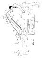
- the trunk lid 124 can therefore be opened regardless of the position of the roof panel 120, even with the roof panel 120 overlying it, so that a user can store or remove baggage 142 (e.g. Figure 4 ).
- the origin of this limitation can be seen with particular reference to Figure 4 , in which it can be seen that the leading edge 134 of the cover panel 130 scribes an arc around the common pivot axis 122. If this were to be a feasible operation, it would bring the leading edge 134 of the cover panel 130 into interference with the back-light 118, the interference being represented by disappearance of the clearance gap D1 (visible in Figure 3 ) and the creation of an imaginary overlap D2 in the open position of the trunk lid 124 (visible in Figure 4 ).
- An objective of the present invention is to specifically overcome the limitation just discussed concerning the opening-angle of the trunk lid and cover panel assembly in our initial design, i.e. the design in the example illustrated with reference to Figures 1 to 4 .
- the present invention proposes an improved version of our initial proposal ( Figures 1 to 4 ) and a preferred embodiment of this improvement will now be discussed with particular reference to Figures 5 to 14 .
- the improvement consists of disassociating the roof panel axis and the trunk lid axis in such a manner as to be able to open the trunk lid to a useful angle whilst maintaining a clearance gap between the leading edge of the cover panel and the backlight, whether or not the roof panel is open.
- the clearance gap is preferably the minimum practical gap, given manufacturing and styling compromise, and may for example be a panel gap of say 6mm. This is reduced to practice not only in a technically satisfying manner, but also stylistically as will now be disclosed in greater detail.
- a vehicle 10 comprising a body shall 12 that defines a passenger compartment 14 and a trunk space 16 for the storage of goods/luggage 142.
- the passenger compartment 14 extends rearwards from a front windshield 18 to an upstanding rigid element 20, which may be in the form of a roll bar and/or an upright rear backlight and may be permanently fixed in position.
- an upstanding rigid element 20 shall indeed be consistently referred to for convenience as a backlight 20, made up from a rear window 22 surrounded by a roll bar/rigid frame 24.
- the whole backlight assembly 20 of the present embodiment is permanently fixed in position, extending substantially vertically from a cross member 26 that traverses the of the passenger compartment 14.
- the rear cross member 26 may usefully incorporate channel means, configured for draining water and associated with a drain channel directing the rain water down and ultimately onto the road surface.
- a rigid and one-piece roof panel 28 is provided which, when in its closed position, covers the passenger compartment 14. In the closed position (e.g. Figures 5 and 6 ) the roof panel 28 extends forwards from an upper contour or sealing ledge of the backlight 20 across the gap between the back light 20 and an upper-edge/header of the windshield 18.
- a first sealing bead 30 is carried by the lower front edge of the roof panel 28 and interposed between it and an upper edge of the windshield 18.
- a second sealing bead 32 is carried by the roof panel and interposed between it and an upper sealing ledge 34 of the back light 20.
- the roof panel 28 is mounted to the body shell 12 by a pair of pivot mountings 36, positioned one on each side of the cross member 26.
- the roof panel 28 can be pivoted out of its closed position covering the passenger compartment 14, back over itself 180° via a transversely orientated roof axis 38 and into an open position behind the backlight 20.
- the pivot mountings 36 preferably each comprise a buttress 40 that is in the form of a freestanding pillar, rigidly fixed to the cross-member 26.
- the roof pivot axis 38 lies on a plane significantly above the waistline W/L of the vehicle 10, but also significantly below the roofline, for example about half way between the two of them.
- the rear window 20 may be formed with a bulge outwards to accommodate the buttresses 40, in which case the buttresses 40 could act as mounting points for the like of or other devices needing rigid anchorage.
- the buttresses 40 could be incorporated directly as part of the frame/roll-bar 24 surrounding the rear window 22.
- Each buttress 40 supports a pivot axle 42, axially aligned with its counterpart on an opposing buttress 40 on the opposite side of the cross-member 26.
- the roof panel 28 could be manually pivotable about the roof axis 38.
- a motor means is provided for powered operation of the roof pivoting and may be embodied in the form of an endless chain, belt drive, driveshaft and bevel gears or similar, rising up the inside of one or both buttresses 40 from a motor drive unit below the pivot axis 40.
- the motor means comprises a single motor unit down below only one of the buttresses 40, with an endless chain running up the inside of the buttress 40 concerned on to a drive gear connected to the buttress pivot axle 42 in the pivot mounting assembly 36 of that side of the vehicle 10.
- the roof panel 28 is operably connected to each buttress pivot axle 42 by at least one swinging arm 44, and preferably by a pair of them disposed one on each side of the roof panel 28.
- the swinging arms 44 are configured to pick up the roof panel 28 out of its closed position, i.e. to raise it substantially simultaneously out of contact with the windshield 18 and the backlight 20. This has the advantage of avoiding abrasive wear to the seals or other damage that is characteristic of systems in which a backlight swings over itself in unison with the roof panel.
- the swing arms 44 continue to move about the roof pivot axis 38 and thereby swing the roof panel 28 substantially 180° over itself and to place it into its open position, in which it is upside-down and overlying a trunk-lid 46 that covers up the trunk space 16.
- the swing arms 44 extend forward of the roof pivot axis 38 when the roof panel 28 is in its closed position and the roof pivot axis 38 is itself rather higher than the vehicle waistline W/L, it will be appreciated that, when the roof panel 28 is in its open position, it is below and rearwards of the roof pivot axis 38.
- a trunk-lid 46 covers the trunk space 16 and it may rest on a sealing bead 48 that surrounds the access opening to the trunk space 16.
- the trunk-lid 46 further comprises a rear panel 50 that rises upwards from the rear edge of the trunk-lid 46 and which supports a cover panes 52 by hinge means, in the form of a swan-neck hinge 54.
- the trunk lid 46, rear panel 50 and cover panel 52 define a storage space 56 for the roof panel 28 when it is in its open position.
- the storage space 56 of the present invention is outside of and separated from the trunk space 16, so it does not take away storage capacity.
- the cover panel 52 is an additional part that both protects the roof panel 28 from the elements and hides it from view. Hiding the roof panel 28 from view is not only aesthetically more pleasing than the open arrangements of Pattee, Chevstov and Fioravanti, but allows a design of roof panel seals 30, 32 that concentrates on functionality, thereby compensating somewhat the extra cost of the cover panel arrangement 52.
- the cover panel 52 of the preferred embodiment can be opened by raising its leading edge 58 upwards to at least the height necessary to allow the roof panel 28 to pivot over into its open position overlying the trunk lid 46.
- the cover panel 52 can then be pivoted down to substantially cover-up the roof panel 28 from view.
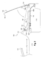
- the kinematics of this sequence of events can be seen with particular reference to Figures 5 to 9 .
- the roof panel 28 is in its closed position covering over the passenger compartment.
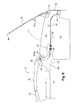
- the cover panel 52 has been raised and in Figure 7 the roof panel 28 has been pivoted part way over itself.
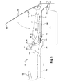
- the roof panel 28 has come to rest in its open position and the cover panel 52 is closing down over it. It will be appreciated that the operations illustrated in Figures 6 to 8 may performed with at least some overlap in the relative pivoting movements of the roof panel 28 and cover panel 52.
- the pivot axis 38 of the roof panel 28 may be positioned substantially identically to the pivot axis 122 of the arrangement in Figures 1 to 4 , which is to say significantly above the waistline W/L of the vehicle but below the level of the top of the backlight 20. As illustrated, the pivot axis 38 may therefore conveniently be positioned substantially half way between the plane of the trunk lid 46 and the plane in which sits the roof panel 28 when it is closed. In this manner, the pivoting of the swinging arms 44 between their limit-stops results in substantially 180° movement of the roof panel 28, bringing it to rest overlying the trunk lid 46.
- the addition of the cover panel 52 in the preferred embodiment brings with it the requirement to keep to a minimum the gap from the leading edge 58 of the cover panel 52 to the rear face of the backlight 20.
- the pivot axis 60 of the trunk lid 46 is disassociated from the pivot axis 38 of the roof panel 28 and does not lie along it.
- the trunk lid pivot axis 60 in the preferred embodiment is located transversely across the vehicle body 12 on a plane that is above and forwards of the plane of the roof panel pivot axis 38. That means that the trunk lid pivot axis 60 is preferably more than half way up between the waistline W/L and the plane of the closed roof panel 28 or upper surface of the backlight 20.
- the trunk lid 46 is connected to its pivot axis 60 by a pair of trunk lid hinges 62, in the form of metal plate stampings substantially in "L" shape that are fixed to the trunk lid 46 along the foot of the "L” and to a trunk lid pivot axle 64 at the upper point of the "L".
- the trunk lid pivot axis 60 and therefore also the trunk lid pivot axle 64 are not only geometrically disassociated from the roof panel pivot axis 38. Indeed, the trunk lid pivot axle 64 is physically disassociated from all of the roof panel pivot mounting arrangement 36.
- the side paneling 66 of the body shell 12 rises up in a ramp from the rear of the vehicle 10 to well above the waistline W/L, so as to form the sides of the storage space 56 and to cover the roof panel pivot mountings 36 from side view.
- a trunk lid pivot axle 64 is mounted on the inward facing side of the ramped-up body shell sides 66, one on each side of the body shell 12 above and forward of the roof pivot axis 38.
- the disassociation of the roof axis 38 from the trunk lid axis 60 is therefore reduced to practice in such a manner that, during opening of the trunk lid 46 with the cover panel 52 in its closed position, the leading edge 58 of the cover panes 52 follows a path that maintains substantially the same clearance gap J1 in both open and closed positions of the trunk lid 46. This is the case regardless of whether the roof panel 28 is closed over the passenger compartment 14 or open and overlying the truck lid 46 underneath the cover panel 52.
- the relationship that defines the clearance gap J1 is the one between the backlight 20 and the arc scribed by the leading edge 58 of the cover panel as it pivots around the trunk lid axis 60 between the open and closed positions of the truck lid 46.
- This can be derived by way of one example from Figure 14 .
- Figure 14 shows in side-view how an area 68 can be constructed such that placing the trunk lid pivot axis 60 in that area will avoid the interference D2 suffered by the arrangement of Figure 4 . Construction of the safe area 68 overcomes the initial problem of guaranteeing a clearance gap between the leading edge 58 of the cover panel 52 and the backlight 20 and that at least ensures that the trunk lid 46 can be opened fully.
- the same geometry illustrates how an optimum position can be found so as to provide substantially the same gap between the leading edge 58 of the cover panel 52 and the backlight 20 for both fully open and fully closed positions of the trunk lid 46.
- the trunk lid pivot axis 60 is represented by the point "P", the cover panel 52 by “ a” and the leading edge 58 of the cover panel by the point "P1".
- the line “b” represents the datum against which the clearance gap "J1" must be maintained (i.e. the shape of the backlight 20).
- the line “b1” represents the limit to which the leading edge "P1" of the cover panel “a” is allowed reach with respect to the datum "b” , so as to maintain the consistent gap "J1" at the ends of pivotal travel of the trunk lid 46.
- the distance between “P” and “P1” represents the distance between the cover panel leading edge 58 and the trunk lid pivot axis 60.
- a series of possible locations ( “1” to “4" ) is illustrated for “P” , running down the line “b2" away from a single position of “P1” .
- the locations ( “1” to “4" ) illustrate an increasing length of radius and therefore of arc scribed by “P1” about “P” , which translates into “P1” climbing proportionately further up “b1” , by way of providing the substantially constant clearance gap "J1" in both open and closed positions of the trunk lid 46.
- an area 68 can be developed in the diagram in which a designer knows he can position the trunk lid pivot axis "P" with respect to the backlight 20 and/or roof pivot axis 38 without risking interference D2. He will also have the information necessary to develop the ideal line "b2" along which to position "P” , i.e. so as to ensure a consistent clearance gap J1 between open and closed positions of the trunk lid 46.
- the clearance gap J1 is consistent (e.g. 6mm) in each of the open and closed positions of the trunk lid 46 but, as the leading edge 58 of the cover panel 52 scribes an arc whilst opening, the gap will first increase and then decrease along the arc. It is considered most important aesthetically that a user sees a constant gap J1 at the opposite ends of the travel and that they are unlikely to be unduly distracted by the variation in the gap that takes place during trunk lid opening.
- the trunk lid pivot axis 60 has been position above the waistline W/L of the vehicle and forward of the roof panel pivot axis 38.
- the position of the trunk lid pivot axis 60 is, furthermore, in front of roof panel pivot axis 38.
- the position chosen for the preferred embodiment is therefore at or close to the point "P";"3" on "b2" . It will however be appreciated that other positions are possible, in dependence on the safe area 68 developed in a diagram that is equivalent to Figure 5 and that applies to another embodiment of the present invention.
- the lack of relative movement meant that the support means 138A,B could for example be simple rubber blocks.
- trunk lid pivot axis 60 causes relative movement " ⁇ " during opening between the trunk lid 46 and cover panel 52 combination and the opened roof panel 28.
- the distance " ⁇ " of relative movement depends on how far from each other the roof pivot axis 38 and the trunk pivot axes 60 are separated.
- the roof panel 28 did not actuary contact either the trunk-lid 46 or the cover panes 52, e.g. using stops in the rotary mechanism.
- the roof panel 28 in the preferred embodiment is held in position between the trunk lid 46 and the cover panel 50 by support means rising from the former and depending from the latter.
- the support means of the preferred embodiment guide relative movement in such a way as to minimize or preferably avoid abrasion of the roof panel 28,
- guiding means might be at least one block that is configured to allow the roof panel 28 to slide along it during opening.
- the guiding means are reduced to practice as rotary members, more particularly in the form of roller or caster wheels, advantageously made in a resilient or vibration absorbing material such as rubber.
- the wheels 70 on the cover panel 52 are preferably positioned forward of the wheels 72 on the trunk lid 46.
- the wheels 70, 72 on one or both of the cover panel 52 and trunk lid 46 are preferably adapted to the shape of the portion of the roof panel along which they turn. This can be seen by way of example with particular reference to Figure 13 , in which the wheel 72 rising from the trunk lid 46 are frustro-conical and facing inwards.
- a convertible vehicle 10 which has a rigid roof panel 28 configured to pivot 180° over itself into an open position in which it overlies a trunk lid 46.
- the trunk lid 46 supports a rear-hinged cover panel 52 that is configured to close down over the open roof panel 28 to hide it from view,
- the pivot axis 60 of the trunk lid 46 is disassociated from the pivot axis 38 of the roof panel 28, such that the trunk lid 46 can be pivoted about its axis whilst ensuring that the leading edge 58 of the cover panel 52 will not hit the rear backlight 20 of the passenger compartment 14 when the trunk space 16 is accessed.
Priority Applications (3)
| Application Number | Priority Date | Filing Date | Title |
|---|---|---|---|
| EP09305332A EP2241466B1 (de) | 2009-04-17 | 2009-04-17 | Klappfahrzeug |
| AT09305332T ATE512013T1 (de) | 2009-04-17 | 2009-04-17 | Klappfahrzeug |
| PCT/EP2009/063069 WO2010118788A1 (en) | 2009-04-17 | 2009-10-08 | A convertible vehicle |
Applications Claiming Priority (1)
| Application Number | Priority Date | Filing Date | Title |
|---|---|---|---|
| EP09305332A EP2241466B1 (de) | 2009-04-17 | 2009-04-17 | Klappfahrzeug |
Publications (2)
| Publication Number | Publication Date |
|---|---|
| EP2241466A1 true EP2241466A1 (de) | 2010-10-20 |
| EP2241466B1 EP2241466B1 (de) | 2011-06-08 |
Family
ID=41060090
Family Applications (1)
| Application Number | Title | Priority Date | Filing Date |
|---|---|---|---|
| EP09305332A Active EP2241466B1 (de) | 2009-04-17 | 2009-04-17 | Klappfahrzeug |
Country Status (3)
| Country | Link |
|---|---|
| EP (1) | EP2241466B1 (de) |
| AT (1) | ATE512013T1 (de) |
| WO (1) | WO2010118788A1 (de) |
Cited By (2)
| Publication number | Priority date | Publication date | Assignee | Title |
|---|---|---|---|---|
| FR2982536A1 (fr) * | 2011-11-14 | 2013-05-17 | Peugeot Citroen Automobiles Sa | Vehicule cabriolet equipe d'une coque de fixation d'un toit amovible. |
| WO2016175673A1 (en) * | 2015-04-27 | 2016-11-03 | Vîlcelaru Daniel | Method of functioning the retractable hard top system for convertible vehicles |
Families Citing this family (1)
| Publication number | Priority date | Publication date | Assignee | Title |
|---|---|---|---|---|
| ITBO20110476A1 (it) | 2011-08-01 | 2013-02-02 | Ferrari Spa | Automobile con un tetto apribile provvista di montanti verticali interni ed esterni |
Citations (11)
| Publication number | Priority date | Publication date | Assignee | Title |
|---|---|---|---|---|
| US3823977A (en) | 1971-11-03 | 1974-07-16 | Pininfarina Spa Carrozzeria | Motor vehicle bodywork with rigid sunshine roof |
| EP0277295A2 (de) * | 1987-01-31 | 1988-08-10 | Dr.Ing.h.c. F. Porsche Aktiengesellschaft | Festes Klappdach für einen Personenwagen |
| US4950022A (en) | 1989-08-30 | 1990-08-21 | Pattee Clark C | Convertible hard-top passenger vehicle |
| EP0901421A1 (de) | 1996-05-29 | 1999-03-17 | Fioravanti S.r.l. | Motorfahrzeug mit rigidem dach und manueller bedienung |
| EP1234704A2 (de) | 2001-02-22 | 2002-08-28 | Fioravanti S.r.l. | Ein Kraftfahrzeug mit einem öffnungsfähigen Hard-Top |
| DE10116710A1 (de) * | 2001-04-04 | 2002-10-24 | Edscha Cabrio Dachsys Gmbh | Verdeck für ein Cabriolet-Fahrzeug |
| US20040222658A1 (en) * | 2003-03-24 | 2004-11-11 | Christopher Dilluvio | Retractable roof structural system |
| US7172236B1 (en) | 2006-07-27 | 2007-02-06 | American Sunroof Corporation | Targa roof system with a buttress |
| DE102006021227A1 (de) * | 2006-05-06 | 2007-11-08 | Wilhelm Karmann Gmbh | Cabrioletfahrzeug |
| FR2916726A1 (fr) * | 2007-05-29 | 2008-12-05 | Heuliez Sa | Procede de deplacement d'un capot d'un vehicule. |
| DE202008001247U1 (de) * | 2008-01-28 | 2009-06-10 | BROSE SCHLIEßSYSTEME GMBH & CO. KG | Kraftfahrzeug |
-
2009
- 2009-04-17 AT AT09305332T patent/ATE512013T1/de not_active IP Right Cessation
- 2009-04-17 EP EP09305332A patent/EP2241466B1/de active Active
- 2009-10-08 WO PCT/EP2009/063069 patent/WO2010118788A1/en active Application Filing
Patent Citations (12)
| Publication number | Priority date | Publication date | Assignee | Title |
|---|---|---|---|---|
| US3823977A (en) | 1971-11-03 | 1974-07-16 | Pininfarina Spa Carrozzeria | Motor vehicle bodywork with rigid sunshine roof |
| EP0277295A2 (de) * | 1987-01-31 | 1988-08-10 | Dr.Ing.h.c. F. Porsche Aktiengesellschaft | Festes Klappdach für einen Personenwagen |
| US4819982A (en) | 1987-01-31 | 1989-04-11 | Dr. Ing. H.C.F. Porsche Aktiengesellschaft | Rotatable top for a passenger car |
| US4950022A (en) | 1989-08-30 | 1990-08-21 | Pattee Clark C | Convertible hard-top passenger vehicle |
| EP0901421A1 (de) | 1996-05-29 | 1999-03-17 | Fioravanti S.r.l. | Motorfahrzeug mit rigidem dach und manueller bedienung |
| EP1234704A2 (de) | 2001-02-22 | 2002-08-28 | Fioravanti S.r.l. | Ein Kraftfahrzeug mit einem öffnungsfähigen Hard-Top |
| DE10116710A1 (de) * | 2001-04-04 | 2002-10-24 | Edscha Cabrio Dachsys Gmbh | Verdeck für ein Cabriolet-Fahrzeug |
| US20040222658A1 (en) * | 2003-03-24 | 2004-11-11 | Christopher Dilluvio | Retractable roof structural system |
| DE102006021227A1 (de) * | 2006-05-06 | 2007-11-08 | Wilhelm Karmann Gmbh | Cabrioletfahrzeug |
| US7172236B1 (en) | 2006-07-27 | 2007-02-06 | American Sunroof Corporation | Targa roof system with a buttress |
| FR2916726A1 (fr) * | 2007-05-29 | 2008-12-05 | Heuliez Sa | Procede de deplacement d'un capot d'un vehicule. |
| DE202008001247U1 (de) * | 2008-01-28 | 2009-06-10 | BROSE SCHLIEßSYSTEME GMBH & CO. KG | Kraftfahrzeug |
Non-Patent Citations (1)
| Title |
|---|
| SOVIET DESIGN IN INTERNATIONAL CONTEST, September 1989 (1989-09-01), pages 2 |
Cited By (5)
| Publication number | Priority date | Publication date | Assignee | Title |
|---|---|---|---|---|
| FR2982536A1 (fr) * | 2011-11-14 | 2013-05-17 | Peugeot Citroen Automobiles Sa | Vehicule cabriolet equipe d'une coque de fixation d'un toit amovible. |
| WO2016175673A1 (en) * | 2015-04-27 | 2016-11-03 | Vîlcelaru Daniel | Method of functioning the retractable hard top system for convertible vehicles |
| CN107921847A (zh) * | 2015-04-27 | 2018-04-17 | 威尔塞拉儒·丹尼尔 | 运行敞篷车的可伸缩硬顶系统的方法 |
| US10343505B2 (en) | 2015-04-27 | 2019-07-09 | Daniel VILCELARU | Method of functioning the retractable hard top system for convertible vehicles |
| CN107921847B (zh) * | 2015-04-27 | 2021-05-11 | 威尔塞拉儒·丹尼尔 | 运行敞篷车的可伸缩硬顶系统的方法 |
Also Published As
| Publication number | Publication date |
|---|---|
| WO2010118788A1 (en) | 2010-10-21 |
| EP2241466B1 (de) | 2011-06-08 |
| ATE512013T1 (de) | 2011-06-15 |
Similar Documents
| Publication | Publication Date | Title |
|---|---|---|
| US6386615B2 (en) | Tonneau cover system | |
| US8220861B2 (en) | Convertible vehicle body | |
| EP1912815B1 (de) | Auto mit sonnendach | |
| EP1706284B1 (de) | Schliessvorrichtung für ein mit einer luke und einem sonnendach versehenes fahrzeug | |
| EP2241466B1 (de) | Klappfahrzeug | |
| US2967073A (en) | Motor vehicle body with a pivotal closure | |
| GB2420530A (en) | Retracting roof mechanism | |
| US6863333B2 (en) | Shelf of a convertible | |
| US20080030044A1 (en) | Roof Structure for a Rigid, Openable Vehicle Roof | |
| US7014247B2 (en) | Hardtop convertible | |
| EP1320467B1 (de) | Versenkbares dach für ein fahrzeug und fahrzeug, insbesondere vom typ pick-up, mit einem solchen dach | |
| US11938800B2 (en) | Tonneau cover with torsion element | |
| US20030025349A1 (en) | Motor vehicle having a folding roof which can be opened | |
| US6623070B2 (en) | Roof arrangement for a vehicle | |
| FR2853601A1 (fr) | Systeme de plage arriere de vehicule | |
| EP1706283A1 (de) | Ein sonnendach und eine luke umfassendes fahrzeug | |
| EP1882606B1 (de) | Cabriolet-Fahrzeug | |
| EP1564053A1 (de) | Faltbares Hardtop für Fahrzeug | |
| WO2005075230A1 (fr) | Toit escamotable de vehicule | |
| WO2005075229A1 (fr) | Toit escamotable de vehicule | |
| WO2005075232A1 (fr) | Toit escamotable de vehicule | |
| FR2957853A1 (fr) | Vehicule automobile equipe d'un toit escamotable dont l'element arriere portant la lunette arriere est conformable. | |
| FR2880844A1 (fr) | Vehicule automobile transformable en vehicule decouvert type cabriolet | |
| FR2824300A1 (fr) | Vehicule du type berline transformable en break | |
| FR2934973A1 (fr) | Structure d'habitacle escamotable d'un vehicule automobile, son procede d'escamotage et vehicule automobile equipe d'une telle structure |
Legal Events
| Date | Code | Title | Description |
|---|---|---|---|
| PUAI | Public reference made under article 153(3) epc to a published international application that has entered the european phase |
Free format text: ORIGINAL CODE: 0009012 |
|
| 17P | Request for examination filed |
Effective date: 20091006 |
|
| AK | Designated contracting states |
Kind code of ref document: A1 Designated state(s): AT BE BG CH CY CZ DE DK EE ES FI FR GB GR HR HU IE IS IT LI LT LU LV MC MK MT NL NO PL PT RO SE SI SK TR |
|
| GRAP | Despatch of communication of intention to grant a patent |
Free format text: ORIGINAL CODE: EPIDOSNIGR1 |
|
| GRAS | Grant fee paid |
Free format text: ORIGINAL CODE: EPIDOSNIGR3 |
|
| GRAA | (expected) grant |
Free format text: ORIGINAL CODE: 0009210 |
|
| AK | Designated contracting states |
Kind code of ref document: B1 Designated state(s): AT BE BG CH CY CZ DE DK EE ES FI FR GB GR HR HU IE IS IT LI LT LU LV MC MK MT NL NO PL PT RO SE SI SK TR |
|
| REG | Reference to a national code |
Ref country code: GB Ref legal event code: FG4D |
|
| REG | Reference to a national code |
Ref country code: CH Ref legal event code: EP |
|
| REG | Reference to a national code |
Ref country code: IE Ref legal event code: FG4D |
|
| REG | Reference to a national code |
Ref country code: DE Ref legal event code: R096 Ref document number: 602009001494 Country of ref document: DE Effective date: 20110721 |
|
| REG | Reference to a national code |
Ref country code: NL Ref legal event code: VDEP Effective date: 20110608 |
|
| PG25 | Lapsed in a contracting state [announced via postgrant information from national office to epo] |
Ref country code: HR Free format text: LAPSE BECAUSE OF FAILURE TO SUBMIT A TRANSLATION OF THE DESCRIPTION OR TO PAY THE FEE WITHIN THE PRESCRIBED TIME-LIMIT Effective date: 20110608 Ref country code: NO Free format text: LAPSE BECAUSE OF FAILURE TO SUBMIT A TRANSLATION OF THE DESCRIPTION OR TO PAY THE FEE WITHIN THE PRESCRIBED TIME-LIMIT Effective date: 20110908 Ref country code: LT Free format text: LAPSE BECAUSE OF FAILURE TO SUBMIT A TRANSLATION OF THE DESCRIPTION OR TO PAY THE FEE WITHIN THE PRESCRIBED TIME-LIMIT Effective date: 20110608 Ref country code: SE Free format text: LAPSE BECAUSE OF FAILURE TO SUBMIT A TRANSLATION OF THE DESCRIPTION OR TO PAY THE FEE WITHIN THE PRESCRIBED TIME-LIMIT Effective date: 20110608 |
|
| PG25 | Lapsed in a contracting state [announced via postgrant information from national office to epo] |
Ref country code: GR Free format text: LAPSE BECAUSE OF FAILURE TO SUBMIT A TRANSLATION OF THE DESCRIPTION OR TO PAY THE FEE WITHIN THE PRESCRIBED TIME-LIMIT Effective date: 20110909 Ref country code: LV Free format text: LAPSE BECAUSE OF FAILURE TO SUBMIT A TRANSLATION OF THE DESCRIPTION OR TO PAY THE FEE WITHIN THE PRESCRIBED TIME-LIMIT Effective date: 20110608 Ref country code: AT Free format text: LAPSE BECAUSE OF FAILURE TO SUBMIT A TRANSLATION OF THE DESCRIPTION OR TO PAY THE FEE WITHIN THE PRESCRIBED TIME-LIMIT Effective date: 20110608 Ref country code: CY Free format text: LAPSE BECAUSE OF FAILURE TO SUBMIT A TRANSLATION OF THE DESCRIPTION OR TO PAY THE FEE WITHIN THE PRESCRIBED TIME-LIMIT Effective date: 20110608 Ref country code: ES Free format text: LAPSE BECAUSE OF FAILURE TO SUBMIT A TRANSLATION OF THE DESCRIPTION OR TO PAY THE FEE WITHIN THE PRESCRIBED TIME-LIMIT Effective date: 20110919 Ref country code: SI Free format text: LAPSE BECAUSE OF FAILURE TO SUBMIT A TRANSLATION OF THE DESCRIPTION OR TO PAY THE FEE WITHIN THE PRESCRIBED TIME-LIMIT Effective date: 20110608 Ref country code: FI Free format text: LAPSE BECAUSE OF FAILURE TO SUBMIT A TRANSLATION OF THE DESCRIPTION OR TO PAY THE FEE WITHIN THE PRESCRIBED TIME-LIMIT Effective date: 20110608 |
|
| PG25 | Lapsed in a contracting state [announced via postgrant information from national office to epo] |
Ref country code: BE Free format text: LAPSE BECAUSE OF FAILURE TO SUBMIT A TRANSLATION OF THE DESCRIPTION OR TO PAY THE FEE WITHIN THE PRESCRIBED TIME-LIMIT Effective date: 20110608 Ref country code: NL Free format text: LAPSE BECAUSE OF FAILURE TO SUBMIT A TRANSLATION OF THE DESCRIPTION OR TO PAY THE FEE WITHIN THE PRESCRIBED TIME-LIMIT Effective date: 20110608 |
|
| PG25 | Lapsed in a contracting state [announced via postgrant information from national office to epo] |
Ref country code: PT Free format text: LAPSE BECAUSE OF FAILURE TO SUBMIT A TRANSLATION OF THE DESCRIPTION OR TO PAY THE FEE WITHIN THE PRESCRIBED TIME-LIMIT Effective date: 20111010 Ref country code: IS Free format text: LAPSE BECAUSE OF FAILURE TO SUBMIT A TRANSLATION OF THE DESCRIPTION OR TO PAY THE FEE WITHIN THE PRESCRIBED TIME-LIMIT Effective date: 20111008 Ref country code: EE Free format text: LAPSE BECAUSE OF FAILURE TO SUBMIT A TRANSLATION OF THE DESCRIPTION OR TO PAY THE FEE WITHIN THE PRESCRIBED TIME-LIMIT Effective date: 20110608 Ref country code: CZ Free format text: LAPSE BECAUSE OF FAILURE TO SUBMIT A TRANSLATION OF THE DESCRIPTION OR TO PAY THE FEE WITHIN THE PRESCRIBED TIME-LIMIT Effective date: 20110608 |
|
| PG25 | Lapsed in a contracting state [announced via postgrant information from national office to epo] |
Ref country code: PL Free format text: LAPSE BECAUSE OF FAILURE TO SUBMIT A TRANSLATION OF THE DESCRIPTION OR TO PAY THE FEE WITHIN THE PRESCRIBED TIME-LIMIT Effective date: 20110608 Ref country code: SK Free format text: LAPSE BECAUSE OF FAILURE TO SUBMIT A TRANSLATION OF THE DESCRIPTION OR TO PAY THE FEE WITHIN THE PRESCRIBED TIME-LIMIT Effective date: 20110608 |
|
| PLBE | No opposition filed within time limit |
Free format text: ORIGINAL CODE: 0009261 |
|
| STAA | Information on the status of an ep patent application or granted ep patent |
Free format text: STATUS: NO OPPOSITION FILED WITHIN TIME LIMIT |
|
| 26N | No opposition filed |
Effective date: 20120309 |
|
| PG25 | Lapsed in a contracting state [announced via postgrant information from national office to epo] |
Ref country code: DK Free format text: LAPSE BECAUSE OF FAILURE TO SUBMIT A TRANSLATION OF THE DESCRIPTION OR TO PAY THE FEE WITHIN THE PRESCRIBED TIME-LIMIT Effective date: 20110608 |
|
| REG | Reference to a national code |
Ref country code: DE Ref legal event code: R097 Ref document number: 602009001494 Country of ref document: DE Effective date: 20120309 |
|
| PG25 | Lapsed in a contracting state [announced via postgrant information from national office to epo] |
Ref country code: MC Free format text: LAPSE BECAUSE OF NON-PAYMENT OF DUE FEES Effective date: 20120430 |
|
| REG | Reference to a national code |
Ref country code: IE Ref legal event code: MM4A |
|
| PG25 | Lapsed in a contracting state [announced via postgrant information from national office to epo] |
Ref country code: IE Free format text: LAPSE BECAUSE OF NON-PAYMENT OF DUE FEES Effective date: 20120417 |
|
| PG25 | Lapsed in a contracting state [announced via postgrant information from national office to epo] |
Ref country code: MK Free format text: LAPSE BECAUSE OF FAILURE TO SUBMIT A TRANSLATION OF THE DESCRIPTION OR TO PAY THE FEE WITHIN THE PRESCRIBED TIME-LIMIT Effective date: 20110608 |
|
| PG25 | Lapsed in a contracting state [announced via postgrant information from national office to epo] |
Ref country code: BG Free format text: LAPSE BECAUSE OF FAILURE TO SUBMIT A TRANSLATION OF THE DESCRIPTION OR TO PAY THE FEE WITHIN THE PRESCRIBED TIME-LIMIT Effective date: 20110908 |
|
| PG25 | Lapsed in a contracting state [announced via postgrant information from national office to epo] |
Ref country code: MT Free format text: LAPSE BECAUSE OF FAILURE TO SUBMIT A TRANSLATION OF THE DESCRIPTION OR TO PAY THE FEE WITHIN THE PRESCRIBED TIME-LIMIT Effective date: 20110608 |
|
| REG | Reference to a national code |
Ref country code: CH Ref legal event code: PL |
|
| PG25 | Lapsed in a contracting state [announced via postgrant information from national office to epo] |
Ref country code: CH Free format text: LAPSE BECAUSE OF NON-PAYMENT OF DUE FEES Effective date: 20130430 Ref country code: LI Free format text: LAPSE BECAUSE OF NON-PAYMENT OF DUE FEES Effective date: 20130430 |
|
| PG25 | Lapsed in a contracting state [announced via postgrant information from national office to epo] |
Ref country code: TR Free format text: LAPSE BECAUSE OF FAILURE TO SUBMIT A TRANSLATION OF THE DESCRIPTION OR TO PAY THE FEE WITHIN THE PRESCRIBED TIME-LIMIT Effective date: 20110608 |
|
| PG25 | Lapsed in a contracting state [announced via postgrant information from national office to epo] |
Ref country code: LU Free format text: LAPSE BECAUSE OF NON-PAYMENT OF DUE FEES Effective date: 20120417 |
|
| PG25 | Lapsed in a contracting state [announced via postgrant information from national office to epo] |
Ref country code: HU Free format text: LAPSE BECAUSE OF FAILURE TO SUBMIT A TRANSLATION OF THE DESCRIPTION OR TO PAY THE FEE WITHIN THE PRESCRIBED TIME-LIMIT Effective date: 20090417 |
|
| REG | Reference to a national code |
Ref country code: FR Ref legal event code: PLFP Year of fee payment: 7 |
|
| REG | Reference to a national code |
Ref country code: FR Ref legal event code: PLFP Year of fee payment: 8 |
|
| REG | Reference to a national code |
Ref country code: FR Ref legal event code: PLFP Year of fee payment: 9 |
|
| REG | Reference to a national code |
Ref country code: FR Ref legal event code: PLFP Year of fee payment: 10 |
|
| PGFP | Annual fee paid to national office [announced via postgrant information from national office to epo] |
Ref country code: IT Payment date: 20220420 Year of fee payment: 14 Ref country code: GB Payment date: 20220425 Year of fee payment: 14 Ref country code: FR Payment date: 20220421 Year of fee payment: 14 Ref country code: DE Payment date: 20220420 Year of fee payment: 14 |
|
| REG | Reference to a national code |
Ref country code: DE Ref legal event code: R119 Ref document number: 602009001494 Country of ref document: DE |
|
| GBPC | Gb: european patent ceased through non-payment of renewal fee |
Effective date: 20230417 |
|
| PG25 | Lapsed in a contracting state [announced via postgrant information from national office to epo] |
Ref country code: GB Free format text: LAPSE BECAUSE OF NON-PAYMENT OF DUE FEES Effective date: 20230417 |
|
| PG25 | Lapsed in a contracting state [announced via postgrant information from national office to epo] |
Ref country code: GB Free format text: LAPSE BECAUSE OF NON-PAYMENT OF DUE FEES Effective date: 20230417 Ref country code: FR Free format text: LAPSE BECAUSE OF NON-PAYMENT OF DUE FEES Effective date: 20230430 Ref country code: DE Free format text: LAPSE BECAUSE OF NON-PAYMENT OF DUE FEES Effective date: 20231103 |
|
| PG25 | Lapsed in a contracting state [announced via postgrant information from national office to epo] |
Ref country code: IT Free format text: LAPSE BECAUSE OF NON-PAYMENT OF DUE FEES Effective date: 20230417 |