EP2241464A1 - Sliding extensible sun visor for an automobile - Google Patents
Sliding extensible sun visor for an automobile Download PDFInfo
- Publication number
- EP2241464A1 EP2241464A1 EP10159641A EP10159641A EP2241464A1 EP 2241464 A1 EP2241464 A1 EP 2241464A1 EP 10159641 A EP10159641 A EP 10159641A EP 10159641 A EP10159641 A EP 10159641A EP 2241464 A1 EP2241464 A1 EP 2241464A1
- Authority
- EP
- European Patent Office
- Prior art keywords
- sun visor
- guide piece
- rigid portion
- extensible
- winder
- Prior art date
- Legal status (The legal status is an assumption and is not a legal conclusion. Google has not performed a legal analysis and makes no representation as to the accuracy of the status listed.)
- Withdrawn
Links
Images


Classifications
-
- B—PERFORMING OPERATIONS; TRANSPORTING
- B60—VEHICLES IN GENERAL
- B60J—WINDOWS, WINDSCREENS, NON-FIXED ROOFS, DOORS, OR SIMILAR DEVICES FOR VEHICLES; REMOVABLE EXTERNAL PROTECTIVE COVERINGS SPECIALLY ADAPTED FOR VEHICLES
- B60J3/00—Antiglare equipment associated with windows or windscreens; Sun visors for vehicles
- B60J3/02—Antiglare equipment associated with windows or windscreens; Sun visors for vehicles adjustable in position
- B60J3/0204—Sun visors
- B60J3/0213—Sun visors characterised by the mounting means
- B60J3/0234—Mounted slidably
- B60J3/0243—Mounted slidably sliding out from ceiling
Definitions
- the curtain comprises a blackout cloth wound on a winder and a draw bar integral with the free end of the fabric.
- the pull bar is guided in translation along the windshield of the vehicle.
- this type of sun visor if it is for example suitable for vehicles with a large windshield, such as coaches, buses, for example, is not suitable in an automobile for aesthetic reasons.
- An object of the invention is to provide an extensible visor of a motor vehicle which is aesthetic.
- the subject of the invention is a sunshade of the aforementioned type, characterized in that said guide piece is rotatably mounted relative to the support piece between a retracted position corresponding to the retracted configuration of the bumper. and a deployed position corresponding to the deployed configuration of the sun visor, said guide piece having a cam follower surface arranged to cooperate with a cam surface provided on the rigid portion of the curtain and thereby move the piece of guiding the retracted position to and to the extended position by moving the rigid portion of the curtain from said near position to and to said position remote from the reel.
- the invention also relates to a motor vehicle comprising a roof structure part and a covering part covering the structural part, and a sun visor, characterized in that the sun visor is as defined herein. above, the support part of the visor being mounted integral with the structural part and masked by the trim piece.
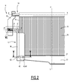
- the Figure 1 illustrates a motor vehicle provided, between the windshield 2 and the roof 4, an extensible visor 6.
- the roof 4 has for example the peculiarity to be glazed, which leaves little room for the storage of a conventional sun visor.
- the sun visor according to the invention has the particularity of being extensible and not requiring the presence of slides mounted fixed on each side of the windshield.
- the visor 6 is illustrated in more detail on the Figures 2 and 3 on which it is respectively represented in deployed configuration and in retracted configuration.
- the sun visor 6 is essentially composed of an extensible curtain and means 12 for guiding the curtain between the retracted and deployed configurations.
- the curtain 10 comprises a shade cloth 16 wrapping around a winder 18, and a rigid portion 22 fixed to the free end 24 of the fabric 16.
- the winder 18 is rotatably mounted on a support piece 26 around an axis X-X, and urges the occulting cloth 16 in the direction of winding.
- the rigid portion 22 is guided by the guide means 12 in a Y-Y extension direction contained in a plane perpendicular to the X-X axis of the winder 18.
- the X-X axis of the retractor 18 is transverse to the vehicle.
- the rigid portion 22 is thus guided between a position close to the winder 18 ( figure 3 ) corresponding to the retracted configuration of the sun visor 6 and a position remote from the retractor 18 ( figure 2 ) corresponding to the deployed configuration of the sun visor. Between these two positions, it passes through a plurality of intermediate positions.
- the rigid portion 22 has a general shape of plate. It forms a draw bar.
- the guide means 12 comprise two slides 30 arranged on each side of the curtain 10 and slidably receiving the respective ends of the rigid portion 22.
- the slides 30 are for example identical.
- Each slide 30 is in fact rotatably mounted relative to the respective support part 26 about an axis ZZ perpendicular to the axes XX and YY, between a retracted position ( figure 3 ) and an extended position ( figure 2 ). In general, the slides 30 are retractable towards the reel 18.
- each slide 30 is for example carried out via a support pin 34.
- Pin 34 is received in support piece 26.
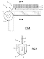
- the slide 30 has, as illustrated on the Figure 4 two flanks 38 for guiding the rigid portion 22 between said remote position and said close position.
- the slide 30 has a cam follower surface 40 cooperating with a cam surface 42 provided on the rigid portion 24.
- the surface 40 is provided at the free end of the slide 30 to provide a greater lever arm.
- the surface 42 extends along a plane inclined at least 5 degrees with respect to a plane tangential to the surface 40 at the area of contact between the surfaces 40 and 42.
- the slide 30 is further biased elastically from the deployed position to and to the near position by a torsion spring 43 of any suitable type (see FIG. Figure 6 ).
- the slide 30, which has a generally elongated shape, extends substantially parallel to the X-X axis of the winder 18, in the extension of the rigid portion 22.
- the deployed position is obtained by a rotation of at least 45 °, for example about 90 ° around the Z-Z axis.
- the slide 30 extends in a direction substantially parallel to the lateral edges 45 of the shade cloth 16.
- the rigid portion 22 is provided with a pin 46 for retaining the rigid portion 22 in a corresponding orifice 48 of the slide 30 to retain the sun visor in deployed configuration.
- the pin 46 is, for example, biased resiliently towards the orifice 48 by a spring 49, as illustrated.
- the stud 46 is alternatively replaced by a retaining relief of any suitable type.
- a plurality of reliefs for example of the nipple type 46, can be provided to retain the rigid portion 22 in different positions.
- the slides 30 are also rotatably mounted about a direction X'-X 'parallel to the axis XX of the winder 18, by rotatably mounting the support pin 34 around the direction X'-X' in the piece 26 of support, as illustrated in more detail on the Figure 6 .
- the direction X'-X ' corresponds to the longitudinal axis of the spindle 34.
- a rotation around the direction X'-X ' makes it possible to orient the rigid portion 22 of the sun visor 6 along different orientation planes, as well as that part of the occulting fabric 16 which is guided by the slide 30 .
- the support pin 34 is also provided with notches 49 ( Figure 6 ) to retain the sun visor 6 in different orientation planes.
- the Figure 1 illustrates the sun visor 6 in different orientations.
- the support pin 34 is, as shown in FIGS. Figures 3 and 6 , mounted movable in translation in the direction X'-X 'so as to reduce the forces exerted at the interface between the cam follower surface 40 and the cam surface 42.
- the support pin 34 is resiliently biased by a spring 50.
- the sun visor 6 is mounted on the motor vehicle by fixing the two support pieces 26 on a vehicle roof structure part 54 ( figure 1 ).
- the structural part 54 is covered by a lining 56 intended to mask the part 54 and the sun visor 6 in retracted configuration.
- the trim 56 has for this purpose a slot 60 for passage of the sun visor 6.
- the invention has many advantages.
- the visor 6 is, in retracted configuration, very discreet and compact. This results in an aesthetic effect.
- the sun visor 6 can be provided on a narrow crossbeam between the windshield 2 and the glazed roof 4.
- the slides 30 provide reliable guidance.
- Cam surfaces 42 and cam follower 40 provide quiet, low friction sliding.
- the translational assembly of the pin 34 reinforces these advantages, as well as the inclination between the surfaces 40 and 42.
- the nipples 46 and notches 49 allowing many possible configurations of the sun visor, inexpensively.
- the sun visor 6 After deployment, the sun visor 6 provides an important occultation surface to the user.
- the sun visor 6 according to the second embodiment of the invention differs essentially in that the slides 30 are replaced by guide bars 64.
- Each bar 64 is received in a corresponding slot 66 of the rigid portion 22 of the curtain 10 so as to guide the rigid portion 22 in the plane of the bar 64.
- this embodiment has the advantage of making it possible to hide, in retracted configuration, the bar 64 in the rigid part 22.
- the edges of the bar 64 and the rigid portion 22 are, in retracted configuration, in contact over substantially the entire length of the bar 64. But, alternatively, the edges are inclined for a point contact and away from the axis (ZZ) of rotation of the bar 64, as in the first embodiment.
- the bar 64 has a slot 68 for receiving the shade cloth 16, so as to limit the size of the visor 6.
- the slot 68 makes it possible to bring the Z-Z axis of the lateral edge 45 of the shade cloth 16 and thus to limit the length necessary for the rigid part 22.
Landscapes
- Engineering & Computer Science (AREA)
- Mechanical Engineering (AREA)
- Operating, Guiding And Securing Of Roll- Type Closing Members (AREA)
- Curtains And Furnishings For Windows Or Doors (AREA)
Abstract
Description
La présente invention concerne un pare-soleil extensible de véhicule automobile, du type comprenant :
- au moins une pièce de support ;
- un rideau extensible comprenant une toile d'occultation et une partie rigide solidaire d'une extrémité de la toile d'occultation ;
- un enrouleur pour enrouler la toile d'occultation, l'enrouleur étant monté sur la pièce de support ;
- au moins une pièce de guidage en translation de ladite partie rigide suivant une direction d'extension entre une position proche de l'enrouleur correspondant à une configuration rétractée du pare-soleil, une position éloignée de l'enrouleur correspondant à une configuration déployée du pare-soleil, et une pluralité de positions intermédiaires.
- at least one support piece;
- an extensible curtain comprising an occulting fabric and a rigid portion secured to one end of the occultation fabric;
- a winder for winding the shade cloth, the winder being mounted on the support piece;
- at least one guide piece in translation of said rigid portion in an extension direction between a position close to the retractor corresponding to a retracted configuration of the sun visor, a position remote from the retractor corresponding to an extended configuration of the pare -Soleil, and a plurality of intermediate positions.
Il existe dans certains véhicules, des pare-soleil formés par un rideau extensible. Le rideau comprend une toile d'occultation enroulée sur un enrouleur et une barre de tirage solidaire de l'extrémité libre de la toile. La barre de tirage est guidée en translation le long du pare-brise du véhicule.In some vehicles there are sunshades formed by an extendable curtain. The curtain comprises a blackout cloth wound on a winder and a draw bar integral with the free end of the fabric. The pull bar is guided in translation along the windshield of the vehicle.
Néanmoins, ce type de pare-soleil, s'il est par exemple adapté pour des véhicules ayant un pare-brise de grandes dimensions, comme par exemple des autocars, des bus, ne convient pas dans une automobile notamment, pour des raisons esthétiques.However, this type of sun visor, if it is for example suitable for vehicles with a large windshield, such as coaches, buses, for example, is not suitable in an automobile for aesthetic reasons.
Un but de l'invention est de fournir un pare-soleil extensible de véhicule automobile qui soit esthétique.An object of the invention is to provide an extensible visor of a motor vehicle which is aesthetic.
A cet effet, l'invention a pour objet un pare-soleil du type précité, caractérisé en ce que ladite pièce de guidage est montée mobile en rotation par rapport à la pièce de support entre une position rétractée, correspondant à la configuration rétractée du pare-soleil, et une position déployée correspondant à la configuration déployée du pare-soleil, ladite pièce de guidage présentant une surface de suiveur de came agencée pour coopérer avec une surface de came prévue sur la partie rigide du rideau et pour déplacer ainsi la pièce de guidage de la position rétractée vers et jusqu'à la position déployée par déplacement de la partie rigide du rideau de ladite position proche vers et jusqu'à ladite position éloignée de l'enrouleur.To this end, the subject of the invention is a sunshade of the aforementioned type, characterized in that said guide piece is rotatably mounted relative to the support piece between a retracted position corresponding to the retracted configuration of the bumper. and a deployed position corresponding to the deployed configuration of the sun visor, said guide piece having a cam follower surface arranged to cooperate with a cam surface provided on the rigid portion of the curtain and thereby move the piece of guiding the retracted position to and to the extended position by moving the rigid portion of the curtain from said near position to and to said position remote from the reel.
Suivant des modes particuliers de réalisation, l'invention comporte une ou plusieurs des caractéristiques suivantes, prise(s) isolément ou suivant toutes les combinaisons techniquement possibles :
- le pare-soleil extensible comprend des moyens de sollicitation élastique de la pièce de guidage de la position déployée vers et jusqu'à la position rétractée ;
- la pièce de guidage est une glissière à l'intérieur de laquelle coulisse la partie rigide ;
- la pièce de guidage est une barre autour de laquelle coulisse la partie rigide ;
- la barre présente une fente de réception de la toile d'occultation ;
- la surface de came de la partie rigide est formée par le bord d'extrémité libre de la partie rigide ;
- la surface de came et la surface de suiveur de came sont conformées de telle sorte que la zone de contact entre les deux surfaces soit située au niveau de l'extrémité libre de la pièce de guidage ;
- la partie rigide et la pièce de guidage présentent des reliefs complémentaires de retenue de la partie rigide dans la position éloignée et/ou dans des positions intermédiaires et/ou dans la position proche, lesdits reliefs comprenant de préférence au moins un téton de retenue pénétrant un orifice correspondant de l'autre de la partie rigide et de la pièce de guidage ;
- la pièce de guidage est montée rotative par rapport à la pièce de support autour d'un axe parallèle à l'axe de l'enrouleur pour orienter le rideau ;
- le pare-soleil comprend deux pièces de guidage agencées de chaque côté du rideau ;
- le pare-soleil comprend une broche de support de la pièce de guidage sur laquelle la pièce de guidage est montée rotative entre la position rétractée et la position déployée ;
- la broche de support est montée mobile en rotation par rapport à la pièce de support autour d'un axe parallèle à l'axe de l'enrouleur pour orienter le rideau ; et
- la broche de support est montée mobile en translation par rapport à la pièce de support suivant ladite direction parallèle à l'axe de l'enrouleur, le pare-soleil comprenant des moyens de sollicitation élastique de la broche de support vers le rideau suivant ladite direction parallèle à l'axe de l'enrouleur, le déplacement de la partie rigide vers la position éloignée déplaçant la broche de support suivant ladite direction parallèle à l'axe de l'enrouleur à l'encontre des moyens de sollicitation élastique.
- the extensible sun visor comprises elastic biasing means of the guide piece of the deployed position to and to the retracted position;
- the guide piece is a slide inside which slides the rigid part;
- the guide piece is a bar around which slides the rigid part;
- the bar has a slot for receiving the occulting cloth;
- the cam surface of the rigid portion is formed by the free end edge of the rigid portion;
- the cam surface and the cam follower surface are shaped so that the contact area between the two surfaces is at the free end of the guide piece;
- the rigid part and the guide piece have complementary reliefs for retaining the rigid part in the remote position and / or in intermediate positions and / or in the near position, said reliefs preferably comprising at least one retaining nipple penetrating a corresponding orifice of the other of the rigid part and the guide piece;
- the guide piece is rotatably mounted relative to the support piece about an axis parallel to the axis of the winder to orient the curtain;
- the sun visor comprises two guide pieces arranged on each side of the curtain;
- the sun visor comprises a support pin of the guide piece on which the guide piece is rotatably mounted between the retracted position and the extended position;
- the support pin is rotatably mounted relative to the support member about an axis parallel to the axis of the winder to orient the curtain; and
- the support pin is mounted movable in translation relative to the support piece in said direction parallel to the axis of the winder, the sun visor comprising elastic biasing means of the support pin to the curtain in said direction parallel to the axis of the reel, the displacement of the rigid portion to the remote position moving the support pin in said direction parallel to the axis of the retractor against the elastic biasing means.
L'invention a également pour objet un véhicule automobile comprenant une pièce de structure de toit et une pièce d'habillage couvrant la pièce de structure, ainsi qu'un pare-soleil, caractérisé en ce que le pare-soleil est tel que défini ci-dessus, la pièce de support du pare-soleil étant montée solidaire de la pièce de structure et masquée par la pièce d'habillage.The invention also relates to a motor vehicle comprising a roof structure part and a covering part covering the structural part, and a sun visor, characterized in that the sun visor is as defined herein. above, the support part of the visor being mounted integral with the structural part and masked by the trim piece.
L'invention sera mieux comprise à la lecture de la description qui va suivre, donnée uniquement à titre d'exemple, et faite en se référant aux dessins annexés, sur lesquels :
- la
Figure 1 est une vue schématique de l'intérieur d'un véhicule automobile muni d'un pare-soleil extensible selon l'invention ; - la
Figure 2 est une demi-vue schématique de face du pare-soleil de laFigure 1 en configuration déployée ; - la
Figure 3 est une vue analogue à laFigure 2 illustrant le pare-soleil en configuration rétractée ; - la
Figure 4 est une vue schématique en coupe suivant la ligne IV - IV de laFigure 3 ; - la
Figure 5 est une vue schématique agrandie en coupe suivant la ligne V - V de la
Figure 2 ; - la
Figure 6 est une vue agrandie d'un détail VI de laFigure 2 ; - la
Figure 7 est une vue schématique partielle en perspective illustrant la partie inférieure d'un pare-soleil extensible selon un deuxième mode de réalisation de l'invention, en configuration déployée ; - la
Figure 8 est une vue analogue du pare-soleil de laFigure 7 en configuration rétractée, pour les traits continus, et dont les traits mixtes indiquent la configuration déployée ; et - la
Figure 9 est une vue en coupe selon la ligne IX - IX de laFigure 8 .
- the
Figure 1 is a schematic view of the interior of a motor vehicle provided with an extensible visor according to the invention; - the
Figure 2 is a schematic half-view of the front of the sun visor of theFigure 1 in deployed configuration; - the
Figure 3 is a view similar to theFigure 2 illustrating the sunshade in retracted configuration; - the
Figure 4 is a schematic sectional view along the line IV - IV of theFigure 3 ; - the
Figure 5 is an enlarged schematic sectional view along line V - V of the
Figure 2 ; - the
Figure 6 is an enlarged view of a detail VI of theFigure 2 ; - the
Figure 7 is a partial schematic perspective view illustrating the lower part of an extensible sun visor according to a second embodiment of the invention, in deployed configuration; - the
Figure 8 is a similar view of the sun visor of theFigure 7 in retracted configuration, for continuous lines, and whose mixed lines indicate the deployed configuration; and - the
Figure 9 is a sectional view along line IX - IX of theFigure 8 .
La
Le pare-soleil selon l'invention présente la particularité d'être extensible et de ne pas nécessiter la présence de glissières montées fixes de chaque côté du pare-brise.The sun visor according to the invention has the particularity of being extensible and not requiring the presence of slides mounted fixed on each side of the windshield.
Le pare-soleil 6 est illustré plus en détail sur les
Les
Le pare-soleil 6 est essentiellement composé d'un rideau 10 extensible et de moyens 12 de guidage du rideau entre les configurations rétractée et déployée.The
Le rideau 10 comprend une toile 16 d'occultation s'enroulant autour d'un enrouleur 18, et une partie rigide 22 fixée à l'extrémité libre 24 de la toile 16.The
L'enrouleur 18 est monté rotatif sur une pièce 26 de support autour d'un axe X-X, et sollicite la toile d'occultation 16 dans le sens de l'enroulement.The
La partie rigide 22 est guidée par les moyens de guidage 12 suivant une direction d'extension Y-Y contenue dans un plan perpendiculaire à l'axe X-X de l'enrouleur 18.The
L'axe X-X de l'enrouleur 18 est transversal au véhicule.The X-X axis of the
La partie rigide 22 est ainsi guidée entre une position proche de l'enrouleur 18 (
La partie rigide 22 a une forme générale de plaque. Elle forme une barre de tirage.The
Les moyens de guidage 12 comprennent deux glissières 30 agencées de chaque côté du rideau 10 et recevant en coulissement les extrémités respectives de la partie rigide 22. Les glissières 30 sont par exemple identiques.The guide means 12 comprise two
Chaque glissière 30 est en effet montée rotative par rapport à la pièce 26 de support respective autour d'un axe Z-Z perpendiculaire aux axes X-X et Y-Y, entre une position rétractée (
Le montage de chaque glissière 30 est par exemple réalisé par l'intermédiaire d'une broche 34 de support. La broche 34 est reçue dans la pièce support 26.The mounting of each
La glissière 30 présente, comme illustré sur la
La rotation de la glissière 30 accompagne le mouvement de la partie rigide 22. A cet effet, la glissière 30 présente une surface 40 de suiveur de came coopérant avec une surface 42 de came prévue sur la partie rigide 24.The rotation of the
La surface 40 est prévue au niveau de l'extrémité libre de la glissière 30 pour assurer un bras de levier plus important.The
Pour un meilleur glissement, la surface 42 s'étend suivant un plan incliné d'au moins 5 degrés par rapport à un plan tangent à la surface 40 au niveau de la zone de contact entre les surfaces 40 et 42.For better sliding, the
Le déplacement de la partie rigide 22 de la position proche à la position éloignée déplace ainsi la glissière 30 de la position rétractée à la position déployée.Moving the
La glissière 30 est en outre sollicitée élastiquement de la position déployée vers et jusqu'à la position proche par un ressort 43 de torsion de tout type adapté (voir
Dans la position rétractée, la glissière 30, qui a une forme générale allongée, s'étend de façon sensiblement parallèle à l'axe X-X de l'enrouleur 18, dans le prolongement de la partie rigide 22.In the retracted position, the
La position déployée est obtenue par une rotation d'au moins 45°, par exemple d'environ 90° autour de l'axe Z-Z. Dans cette position, la glissière 30 s'étend suivant une direction sensiblement parallèle aux bords latéraux 45 de la toile 16 d'occultation.The deployed position is obtained by a rotation of at least 45 °, for example about 90 ° around the Z-Z axis. In this position, the
Comme illustré plus en détail sur la
Une pluralité de reliefs, par exemple de type tétons 46, peuvent être prévus pour retenir la partie rigide 22 dans différentes positions.A plurality of reliefs, for example of the
Les glissières 30 sont également montées rotatives autour d'une direction X'-X' parallèle à l'axe X-X de l'enrouleur 18, par montage rotatif de la broche 34 de support autour de la direction X'-X' dans la pièce 26 de support, comme illustré plus en détail sur la
Une rotation autour de la direction X'-X' permet d'orienter la partie rigide 22 du pare-soleil 6 suivant différents plans d'orientation, de même que la partie de la toile 16 d'occultation qui est guidée par la glissière 30.A rotation around the direction X'-X 'makes it possible to orient the
La broche 34 de support est également munie de crans 49 (
La
En outre, la broche 34 de support est, comme illustré sur les
Ainsi, le déplacement de la partie rigide 22 vers la position éloignée déplace la broche 34 de support à l'encontre du ressort 50.Thus, the displacement of the
Le montage du pare-soleil 6 sur le véhicule automobile est réalisé par la fixation des deux pièces de support 26 sur une pièce 54 de structure du toit du véhicule (
La pièce 54 de structure est recouverte par une garniture 56 destinée à masquer la pièce 54 et le pare-soleil 6 en configuration rétractée. La garniture 56 présente à cet effet une fente 60 de passage du pare-soleil 6.The
En configuration rétractée, seul le centre de la partie rigide 22 du rideau 10 fait saillie par rapport à la garniture 56 de telle sorte que seule la partie 22 est visible par l'utilisateur.In retracted configuration, only the center of the
L'invention présente de nombreux avantages.The invention has many advantages.
Grâce à la rétractabilité des glissières 30, le pare-soleil 6 est, en configuration rétractée, très discret et peu encombrant. Il en résulte un effet esthétique. En outre, le pare-soleil 6 peut être prévu sur une traverse de faible largeur entre le pare-brise 2 et le toit vitré 4.Thanks to the retractability of the
En outre, les glissières 30 assurent un guidage fiable.In addition, the
Les surfaces de came 42 et de suiveur de came 40 assurent un glissement silencieux et à faible frottement. Le montage en translation de la broche 34 renforce ces avantages, de même que l'inclinaison entre les surfaces 40 et 42.Cam surfaces 42 and
Les tétons 46 et les crans 49 permettant de nombreuses configurations possibles du pare-soleil, de façon peu coûteuse.The
Après déploiement, le pare-soleil 6 fournit une surface d'occultation importante à l'utilisateur.After deployment, the
Les
Le pare-soleil 6 selon le deuxième mode de réalisation de l'invention se distingue essentiellement en ce que les glissières 30 sont remplacées par des barres 64 de guidage.The
Chaque barre 64 est reçue dans une fente 66 correspondante de la partie rigide 22 du rideau 10 de façon à guider la partie rigide 22 dans le plan de la barre 64.Each
Comme illustré sur les
Dans l'exemple illustré, les bords de la barre 64 et de la partie rigide 22 sont, en configuration rétractée, en contact sur sensiblement toute la longueur de la barre 64. Mais, en variante, les bords sont inclinés pour un contact ponctuel et éloignés de l'axe (Z-Z) de rotation de la barre 64, comme dans le premier mode de réalisation.In the illustrated example, the edges of the
En outre, la barre 64 présente une fente 68 de réception de la toile 16 d'occultation, de façon à limiter l'encombrement de pare-soleil 6.In addition, the
La fente 68 permet en effet de rapprocher l'axe Z-Z du bord latéral 45 de la toile 16 d'occultation et de limiter ainsi la longueur nécessaire pour la partie rigide 22.The
Claims (11)
Applications Claiming Priority (1)
| Application Number | Priority Date | Filing Date | Title |
|---|---|---|---|
| FR0952523A FR2944482A1 (en) | 2009-04-17 | 2009-04-17 | EXTENSIBLE SLIDING SUNSCREEN FOR MOTOR VEHICLE. |
Publications (1)
| Publication Number | Publication Date |
|---|---|
| EP2241464A1 true EP2241464A1 (en) | 2010-10-20 |
Family
ID=41152138
Family Applications (1)
| Application Number | Title | Priority Date | Filing Date |
|---|---|---|---|
| EP10159641A Withdrawn EP2241464A1 (en) | 2009-04-17 | 2010-04-12 | Sliding extensible sun visor for an automobile |
Country Status (2)
| Country | Link |
|---|---|
| EP (1) | EP2241464A1 (en) |
| FR (1) | FR2944482A1 (en) |
Cited By (1)
| Publication number | Priority date | Publication date | Assignee | Title |
|---|---|---|---|---|
| US10336164B1 (en) | 2017-12-21 | 2019-07-02 | Ford Global Technologies, Llc | Sun visor assembly |
Citations (3)
| Publication number | Priority date | Publication date | Assignee | Title |
|---|---|---|---|---|
| EP1832453A1 (en) * | 2006-03-08 | 2007-09-12 | C.R.F. Società Consortile per Azioni | Sunshade device for motor-vehicles, with shape memory actuator |
| EP1914095A1 (en) * | 2006-10-18 | 2008-04-23 | Wagon Sas | Concealing device with tie rods with lateral concealing element, corresponding automobile and tie rod. |
| EP2000340A1 (en) * | 2007-06-08 | 2008-12-10 | Wagon Sas | Vehicle concealment device with swinging arms linked through cable and corresponding vehicle. |
-
2009
- 2009-04-17 FR FR0952523A patent/FR2944482A1/en not_active Withdrawn
-
2010
- 2010-04-12 EP EP10159641A patent/EP2241464A1/en not_active Withdrawn
Patent Citations (3)
| Publication number | Priority date | Publication date | Assignee | Title |
|---|---|---|---|---|
| EP1832453A1 (en) * | 2006-03-08 | 2007-09-12 | C.R.F. Società Consortile per Azioni | Sunshade device for motor-vehicles, with shape memory actuator |
| EP1914095A1 (en) * | 2006-10-18 | 2008-04-23 | Wagon Sas | Concealing device with tie rods with lateral concealing element, corresponding automobile and tie rod. |
| EP2000340A1 (en) * | 2007-06-08 | 2008-12-10 | Wagon Sas | Vehicle concealment device with swinging arms linked through cable and corresponding vehicle. |
Cited By (1)
| Publication number | Priority date | Publication date | Assignee | Title |
|---|---|---|---|---|
| US10336164B1 (en) | 2017-12-21 | 2019-07-02 | Ford Global Technologies, Llc | Sun visor assembly |
Also Published As
| Publication number | Publication date |
|---|---|
| FR2944482A1 (en) | 2010-10-22 |
Similar Documents
| Publication | Publication Date | Title |
|---|---|---|
| EP1642776B1 (en) | Mounting system of a luggage cover with a rail | |
| EP0538106B1 (en) | Motor-blind of the roller-type for curved window | |
| US8910698B2 (en) | Sunshade assembly | |
| EP2015965B1 (en) | Length-adjustable device for concealing luggage for motor vehicle trunk and motor vehicle equipped with same | |
| EP1769954B1 (en) | Sun visor device for a vehicle's windshield, with a roller blind, and corresponding vehicle | |
| EP0945293B1 (en) | Sun visor in particular for motor vehicle | |
| EP2241464A1 (en) | Sliding extensible sun visor for an automobile | |
| FR2882090A1 (en) | MANUAL AND MULTI-POSITION HORN CURTAIN OCCULTATION DEVICE | |
| EP2072327B1 (en) | Release device of the luggage load space of a motor vehicle | |
| EP1625958B1 (en) | Multi-position roller blind for vehicle, and corresponding vehicle | |
| EP2230115B1 (en) | Device for concealing a glazed roof of an automobile, and corresponding vehicle. | |
| EP3181385B1 (en) | Device for concealing a glazed surface of a motor vehicle roof with non-parallel rails | |
| FR2631374A1 (en) | Roller blind for window of parallelogram form - has screw and ball nut to move blind roller axially as it is rotated | |
| FR2891493A1 (en) | Anti-dazzle screen holder for motor vehicle, has cassette and draw bar stacked with respect to each other to form small anti-dazzle screen holder when sheet is folded, and balancing unit controlling bar to remain parallel to cassette | |
| EP1099580B1 (en) | Roller blind working on the cover of the guide slot, particularly for cars, and assembly method therefor | |
| US20100258256A1 (en) | Sunshade assembly for an automobile | |
| FR2866834A1 (en) | IMPROVED SUN VISOR FOR A MOTOR VEHICLE, AND VEHICLE DOOR EQUIPPED WITH SUCH A SUN VISOR | |
| FR2934203A1 (en) | Roller blind for occulting side window of motor vehicle, has drawing rod mounted in guide rails along rest axis and permanently parallel to rest axis, where rest axis forms angle different from ninety degrees with deployment axis | |
| FR2948900A1 (en) | Glazed element blinding device for e.g. panoramic roof, of vehicle, has sunshade shutter scattering light penetrating into cab interior of vehicle, and shutter roller combined with crosspiece to roll up/unfold sunshade shutter | |
| FR2879969A1 (en) | RETRACTABLE ROOF FOR VEHICLE COMPRISING A MOVEMENT TRANSMISSION DEVICE | |
| FR2942176A1 (en) | Panoramic windscreen's upper part occulting device for motor vehicle, has driving unit with telescopic unit installed on central zone of roof, where telescopic and sliding units are coupled to screen to displace screen between two positions | |
| FR2833535A1 (en) | Roller blind for automobile mounted in case containing winding tube is adapted to selectively unwind canvas, provided with pulling bars, in front of first and second parts of glazed surface either side case | |
| FR3061089B1 (en) | OCCULTATION DEVICE FOR A MOTOR VEHICLE PAVILION WITH REINFORCED CANVAS HOLDING AND GUIDING ELEMENTS AND CORRESPONDING PAVILION | |
| EP1449694A1 (en) | Blind for motor vehicle, with non rectangular screen and slidable decoration, and corresponding motor vehicle | |
| FR3087158A1 (en) | DEPLOYABLE AND RETRACTABLE VEHICLE SUN VISOR |
Legal Events
| Date | Code | Title | Description |
|---|---|---|---|
| PUAI | Public reference made under article 153(3) epc to a published international application that has entered the european phase |
Free format text: ORIGINAL CODE: 0009012 |
|
| AK | Designated contracting states |
Kind code of ref document: A1 Designated state(s): AT BE BG CH CY CZ DE DK EE ES FI FR GB GR HR HU IE IS IT LI LT LU LV MC MK MT NL NO PL PT RO SE SI SK SM TR |
|
| AX | Request for extension of the european patent |
Extension state: AL BA ME RS |
|
| 17P | Request for examination filed |
Effective date: 20110214 |
|
| GRAP | Despatch of communication of intention to grant a patent |
Free format text: ORIGINAL CODE: EPIDOSNIGR1 |
|
| STAA | Information on the status of an ep patent application or granted ep patent |
Free format text: STATUS: THE APPLICATION IS DEEMED TO BE WITHDRAWN |
|
| 18D | Application deemed to be withdrawn |
Effective date: 20130409 |