EP2241406A2 - Tragbares hydraulisches Ziehgerät - Google Patents
Tragbares hydraulisches Ziehgerät Download PDFInfo
- Publication number
- EP2241406A2 EP2241406A2 EP20090163803 EP09163803A EP2241406A2 EP 2241406 A2 EP2241406 A2 EP 2241406A2 EP 20090163803 EP20090163803 EP 20090163803 EP 09163803 A EP09163803 A EP 09163803A EP 2241406 A2 EP2241406 A2 EP 2241406A2
- Authority
- EP
- European Patent Office
- Prior art keywords
- segment
- spring
- portable hydraulic
- jaws
- hydraulic puller
- Prior art date
- Legal status (The legal status is an assumption and is not a legal conclusion. Google has not performed a legal analysis and makes no representation as to the accuracy of the status listed.)
- Withdrawn
Links
Images




Classifications
-
- B—PERFORMING OPERATIONS; TRANSPORTING
- B25—HAND TOOLS; PORTABLE POWER-DRIVEN TOOLS; MANIPULATORS
- B25B—TOOLS OR BENCH DEVICES NOT OTHERWISE PROVIDED FOR, FOR FASTENING, CONNECTING, DISENGAGING, OR HOLDING
- B25B27/00—Hand tools, specially adapted for fitting together or separating parts or objects whether or not involving some deformation, not otherwise provided for
- B25B27/02—Hand tools, specially adapted for fitting together or separating parts or objects whether or not involving some deformation, not otherwise provided for for connecting objects by press fit or detaching same
- B25B27/026—Hand tools, specially adapted for fitting together or separating parts or objects whether or not involving some deformation, not otherwise provided for for connecting objects by press fit or detaching same fluid driven
-
- B—PERFORMING OPERATIONS; TRANSPORTING
- B23—MACHINE TOOLS; METAL-WORKING NOT OTHERWISE PROVIDED FOR
- B23P—METAL-WORKING NOT OTHERWISE PROVIDED FOR; COMBINED OPERATIONS; UNIVERSAL MACHINE TOOLS
- B23P19/00—Machines for simply fitting together or separating metal parts or objects, or metal and non-metal parts, whether or not involving some deformation; Tools or devices therefor so far as not provided for in other classes
- B23P19/02—Machines for simply fitting together or separating metal parts or objects, or metal and non-metal parts, whether or not involving some deformation; Tools or devices therefor so far as not provided for in other classes for connecting objects by press fit or for detaching same
- B23P19/025—For detaching only
-
- B—PERFORMING OPERATIONS; TRANSPORTING
- B25—HAND TOOLS; PORTABLE POWER-DRIVEN TOOLS; MANIPULATORS
- B25B—TOOLS OR BENCH DEVICES NOT OTHERWISE PROVIDED FOR, FOR FASTENING, CONNECTING, DISENGAGING, OR HOLDING
- B25B27/00—Hand tools, specially adapted for fitting together or separating parts or objects whether or not involving some deformation, not otherwise provided for
- B25B27/02—Hand tools, specially adapted for fitting together or separating parts or objects whether or not involving some deformation, not otherwise provided for for connecting objects by press fit or detaching same
- B25B27/023—Hand tools, specially adapted for fitting together or separating parts or objects whether or not involving some deformation, not otherwise provided for for connecting objects by press fit or detaching same using screws
-
- B—PERFORMING OPERATIONS; TRANSPORTING
- B25—HAND TOOLS; PORTABLE POWER-DRIVEN TOOLS; MANIPULATORS
- B25B—TOOLS OR BENCH DEVICES NOT OTHERWISE PROVIDED FOR, FOR FASTENING, CONNECTING, DISENGAGING, OR HOLDING
- B25B27/00—Hand tools, specially adapted for fitting together or separating parts or objects whether or not involving some deformation, not otherwise provided for
- B25B27/02—Hand tools, specially adapted for fitting together or separating parts or objects whether or not involving some deformation, not otherwise provided for for connecting objects by press fit or detaching same
- B25B27/06—Hand tools, specially adapted for fitting together or separating parts or objects whether or not involving some deformation, not otherwise provided for for connecting objects by press fit or detaching same inserting or withdrawing sleeves or bearing races
- B25B27/062—Hand tools, specially adapted for fitting together or separating parts or objects whether or not involving some deformation, not otherwise provided for for connecting objects by press fit or detaching same inserting or withdrawing sleeves or bearing races using screws
-
- B—PERFORMING OPERATIONS; TRANSPORTING
- B25—HAND TOOLS; PORTABLE POWER-DRIVEN TOOLS; MANIPULATORS
- B25B—TOOLS OR BENCH DEVICES NOT OTHERWISE PROVIDED FOR, FOR FASTENING, CONNECTING, DISENGAGING, OR HOLDING
- B25B27/00—Hand tools, specially adapted for fitting together or separating parts or objects whether or not involving some deformation, not otherwise provided for
- B25B27/02—Hand tools, specially adapted for fitting together or separating parts or objects whether or not involving some deformation, not otherwise provided for for connecting objects by press fit or detaching same
- B25B27/06—Hand tools, specially adapted for fitting together or separating parts or objects whether or not involving some deformation, not otherwise provided for for connecting objects by press fit or detaching same inserting or withdrawing sleeves or bearing races
- B25B27/064—Hand tools, specially adapted for fitting together or separating parts or objects whether or not involving some deformation, not otherwise provided for for connecting objects by press fit or detaching same inserting or withdrawing sleeves or bearing races fluid driven
Definitions
- the present invention relates to a portable hydraulic puller according to the preamble of Claim 1. Accordingly, the present invention severally relates to hydraulic pullers and more particularly, to a portable hydraulic puller used to remove bearings, gears, pulleys or any wheel-shaped member from axles.
- a known hydraulic puller taking the disclosure of US Patent No. 5,233,740 for example, primarily comprises a pawl assembly mounted on a casing of a hydraulic power device, and three pawls movably connected to a periphery of the pawl assembly through pivots and links, wherein each said pawl has a free end thereof formed with a hooked portion.
- a hand lever is attached to an upper end of the casing and a hydraulic pipe is attached to a lower end of the casing.
- the hooked portion of the pawls hook a rim of a wheel-shaped member, such as a bearing, a gear or a pulley, and repeatedly rotating the hand lever back and forth causes a movable rod in the hydraulic pipe to press against an axle from which the wheel-shaped member is to be detached, so that the pawls of the pawl assembly pull and remove the wheel-shaped member from the axle.
- a wheel-shaped member such as a bearing, a gear or a pulley
- the aforementioned hydraulic puller has its defects. Firstly, the pivots and links limit the spread of the pawls. Moreover, spread and retraction of the pawls require manual operation where a user has to move the pawls one by one. At last, the traditional hydraulic puller is difficult to hold and operate because it provides no dedicated structure for a user to grasp it.
- the present invention has been accomplished under the circumstances in view to provide a portable hydraulic puller as described in the claims, which is convenient to operate and easy to hold.
- the hydraulic puller comprises a jaw base, a plurality of jaws pivotally connected to the jaw base, a spring assembled to the jaw base for applying a spreading spring force to connecting ends of the jaws; and a control unit assembled to the jaw base for applying a contracting force to the connecting ends of the jaws, wherein the contracting force that is counter to the spreading spring force.
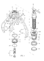
- a portable hydraulic puller proposed in the present invention comprises a jaw base 10, a hydraulic power device 20 set at a center of the jaw base 10, a plurality of jaws 30 connected to a periphery of the jaw base 10 through pivots 31, a spring 40 assembled to the jaw base 10 for applying a spreading spring force to connecting ends 32 of the jaws 30; a control unit 50 assembled to the jaw base 10 for applying a contracting force to the connecting ends 32 of the jaws 30, and a handle 60 attached to the jaw base 10.
- the jaw base 10 includes a circular body 11 and a central sleeve 12 coaxially assembled in the jaw base 10.
- the central sleeve 12 is a tubular member having a predetermined length.
- a horizontally extended positioning portion 126, a first treaded segment 121, a smooth segment 122, a second treaded segment 123 and a groove 127 are successively formed at an outer periphery of the central sleeve 12 while a treaded segment 124 is formed at an inner periphery of the central sleeve 12.
- a circular retaining portion 125 is provided between the smooth segment 122 and the first treaded segment 121.
- the first treaded segment 121 is coupled with an inner threaded surface 111 of the circular body 11.
- the positioning portion 126 abuts against the jaw base 10 so as to position the central sleeve 12 while the smooth segment 122 and the second treaded segment 123 jut out of the circular body 11.
- a plurality of jaw joints 13 and a handle joint 14 are provided at an outer periphery of the circular body 11.
- the hydraulic power device 20 has externally a threaded segment 23 for being coupled with the treaded segment 124 of the central sleeve 12.
- a hand lever 21 is attached to an upper end of the hydraulic power device 20 for controlling the hydraulic power device 20 so as to make a pushing rod 22 axially connected to the hydraulic power device 20 move outside the hydraulic power device 20.
- the pushing rod 22 is composed of an extending member 221 and a pushing member 222.
- the pushing member 222 may be directly assembled to the hydraulic power device 20.
- the pushing member 222 may be assembled to the hydraulic power device 20 with the extending member 221 therebetween.
- the extending member 221 is optionally implemented to increase the pushing rod 22 in length.
- Each of the jaws 30 has one end defined as the connecting end 32 and an opposite end formed with a hooked portion 33 while a shank 35 is connected between the connecting end 32 and the hooked portion 33.
- the shank 35 includes a first segment 351 and a second segment 352 that are integrally formed with a predetermined angle therebetween, wherein the second segment 352 is greater than the first segment 351 in both thickness and width.
- the connecting end 32 is coupled with the jaw joint 13 of the jaw base 10 by the pivot 31 so that the jaw 30 is allowed to swing on the pivot 31.
- a ball 36 is such inlaid in the pivot 31 and propped by a spring (not shown) in the pivot 31 that the ball 36 moves radially inward and outward the pivot 31.
- the connecting end 32 has a protrudent pushing block 34 corresponding to the smooth segment 122 of the central sleeve 12.
- the pushing block 34 comprises a first surface 341 and a second surface 342.
- the spring 40 is mounted around the smooth segment 122 of the central sleeve 12 so that a first end thereof abuts against the retaining portion 125 and a second end thereof abuts against the first surfaces 341 of the pushing blocks 34 of the jaws 30 through a first gasket 15.
- the spring 40 normally applies its spring force to the first surfaces 341 so that the jaws 30 synchronously tilt outward on their respective pivots 31.
- the first gasket 15 serves to evenly distribute the spring force of the spring 40 to the first surfaces 341 of the pushing blocks 34 so that the jaws are allowed to move synchronously under the evenly distributed spring force.
- the control unit 50 is a ring-shaped member with threads 51 formed on its inner periphery for being coupled with the second treaded segment 123 of the central sleeve 12 so that the central sleeve 12 shifts along the second treaded segment 123 under control of the control unit 50.
- a second gasket 52 is settled between the control unit 50 and the second surfaces 342 of the pushing blocks 34 on the jaws 30.
- the second gasket 52 gives a pushing force to the pushing blocks 34 that is counter to and conquers the spring force, so that the jaws 30 synchronously tilt inward on the pivots 31 and have the hooked portions 33 thereof hook a rim of a wheel-shaped member, such as a bearing, a gear or a pulley.
- a C-ring 128 is settled in the groove 127 of the central sleeve 12 so as to define a limit for the control unit 50 moving away from the spring 40.
- the threads 51 are located at a middle segment of the inner periphery of the control unit 50. Said inner periphery receives the second gasket 52 with a first groove 53 at is upper end and contacts the C-ring 128 with bottom 541 of a second groove 54 at its lower end.
- the handle 60 is assembled to the handle joint 14 of the jaw base 10.
- a pivot 141 transversely passing through the handle joint 14 has a ball 142 that such inlaid in the pivot 141 and propped by a spring (not shown) in the pivot 141 that the ball 142 moves radially inward and outward the pivot 141.
- the ball 142 abuts against and inner periphery of the handle joint 14 so as to prevent the pivot 141 from coming off the handle joint 14.
- the pivot 141 has a threaded hole 143 diametrically passing therethrough.
- the handle 60 includes a combining portion 61 for being inserted into the handle joint 14.
- a through hole 62 passing through a proximal end of the handle 60 and the combining portion 61 is aligned with the threaded hole 143.
- a screw 63 pierces through the through hole 62 can get coupled with the threaded hole 143 of the pivot 141 so as to connect the handle 60 and the handle joint 14.
- the handle joint 14 and the handle 60 further have at least a pair of retaining surfaces 147, 64 so that when the retaining surfaces 147, 64 contact mutually, the handle 60 is retained from driving the pivot 141 to rotate.
- the handle 60 allows a user to hold which with one hand for positioning the hydraulic puller and to operate the control unit 50 or the hand lever 21 of the hydraulic power device 20 with the other hand, thus achieving easy and effort-saving operation.
- a lighting device 65 is assembled to the handle 60 so that an LED bulb 66 of the lighting device 65 is exposed at a distal end of the handle 60 while a switch 67 of the lighting device 65 is provided on the handle 60 for easy switching.
- the lighting device 65 serves to provide illumination in operation of the hydraulic puller.
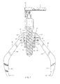
- a sectional view of the hydraulic puller shows the jaws 30 spread apart to the most. Since the control unit 50 contacts the C-ring 128 with the bottom 541 of the second groove 54 at its lower end (referring to FIG. 3 ) , the spring force of the spring 40 is applied to the pushing blocks 34 of the jaws 30 so as to spread the jaws 30 outward.
- the spread jaws 30 then can hook a wheel-shaped member (not shown) with their hooked portions.
- the hydraulic power device 20 drives the pushing rod 22 to apply a heavy load against an axle on which the wheel-shaped member is mounted so that the jaws pull and remove the wheel-shaped member from the axle.
- the hydraulic puller is equipped with three said jaws 30 and one said handle 60.
- the hydraulic puller may be realized by two said jaws 30, assembled to the handle joint 14 and the jaw joint 13 opposite to the handle joint 14, respectively.
- a screw 25 is coupled with the treaded segment 124 of the central sleeve 12.
- the screw 25 has a hexagonal combining portion 251 formed at its upper end and a columnar pushing portion 252 formed at its lower end.
- the combining portion 251 is for being coupled with and driven by an external tool (not shown) to make the screw 25 move upward and downward with respect to the central sleeve 12.
- the pushing portion 252 applies a heavy load to an axle on which a wheel-shaped member is mounted so that the jaws remove the wheel-shaped member from the axle.
Landscapes
- Engineering & Computer Science (AREA)
- Mechanical Engineering (AREA)
- Handcart (AREA)
- Press Drives And Press Lines (AREA)
- Clamps And Clips (AREA)
Applications Claiming Priority (1)
| Application Number | Priority Date | Filing Date | Title |
|---|---|---|---|
| TW98112764A TW201038369A (en) | 2009-04-17 | 2009-04-17 | Portable hydraulic puller |
Publications (1)
| Publication Number | Publication Date |
|---|---|
| EP2241406A2 true EP2241406A2 (de) | 2010-10-20 |
Family
ID=42212187
Family Applications (2)
| Application Number | Title | Priority Date | Filing Date |
|---|---|---|---|
| EP09163801A Withdrawn EP2241405A1 (de) | 2009-04-17 | 2009-06-25 | Hydraulisches Ziehgerät |
| EP20090163803 Withdrawn EP2241406A2 (de) | 2009-04-17 | 2009-06-25 | Tragbares hydraulisches Ziehgerät |
Family Applications Before (1)
| Application Number | Title | Priority Date | Filing Date |
|---|---|---|---|
| EP09163801A Withdrawn EP2241405A1 (de) | 2009-04-17 | 2009-06-25 | Hydraulisches Ziehgerät |
Country Status (2)
| Country | Link |
|---|---|
| EP (2) | EP2241405A1 (de) |
| TW (1) | TW201038369A (de) |
Cited By (11)
| Publication number | Priority date | Publication date | Assignee | Title |
|---|---|---|---|---|
| CN102886668A (zh) * | 2012-08-23 | 2013-01-23 | 中国人民解放军济南军区军械雷达修理所 | 重型机械轮轴拆装设备 |
| CN104249330A (zh) * | 2013-06-27 | 2014-12-31 | 深圳市海洋王照明工程有限公司 | 灯具的开盖治具及开盖方法 |
| CN106826880A (zh) * | 2017-02-15 | 2017-06-13 | 东莞市圣荣自动化科技有限公司 | 一种应用于轴承套圈的机械夹爪 |
| US9802301B2 (en) | 2015-04-22 | 2017-10-31 | David Caston | Multi-head rack and pinion driven pulley puller |
| CN108527247A (zh) * | 2018-07-16 | 2018-09-14 | 岑颖明 | 一种轴承拆卸工具 |
| GB2576583A (en) * | 2018-10-29 | 2020-02-26 | Bo Chen Hung Co Ltd | Detachment puller |
| EP3984700A1 (de) * | 2020-10-19 | 2022-04-20 | Yi-Fang Chen | Abziehvorrichtung |
| EP3984701A1 (de) * | 2020-10-19 | 2022-04-20 | Yi-Fang Chen | Abziehvorrichtung |
| EP3988246A1 (de) * | 2020-10-20 | 2022-04-27 | Yi-Fang Chen | Klauenanordnung einer abziehvorrichtung |
| CN114406950A (zh) * | 2021-12-22 | 2022-04-29 | 劳水养 | 轴承拉拔器 |
| US20220152800A1 (en) * | 2020-11-18 | 2022-05-19 | Yi-Fang Chen | Puller |
Families Citing this family (15)
| Publication number | Priority date | Publication date | Assignee | Title |
|---|---|---|---|---|
| EP2607021B1 (de) * | 2011-12-19 | 2015-05-06 | Schweizerische Bundesbahnen SBB | Abzugsvorrichtung für Radsatzlager von Schienenfahrzeugen |
| CN102785066A (zh) * | 2012-06-30 | 2012-11-21 | 国电联合动力技术(连云港)有限公司 | 一种适用于大型风机变桨减速箱的安装装置 |
| CN103522037B (zh) * | 2013-07-19 | 2015-10-28 | 柳州职业技术学院 | 矿用电机皮带轮自动拆卸压力机 |
| CN103433888B (zh) * | 2013-08-29 | 2016-12-28 | 怀宁上峰水泥有限公司 | 一种多用组合移动拉马 |
| CN104552128B (zh) * | 2013-10-23 | 2016-10-19 | 谢佳 | 应用于探测器的起拔器 |
| CN104607967B (zh) * | 2015-02-10 | 2017-01-18 | 中国科学院上海光学精密机械研究所 | 长度可变的旋转工装夹具 |
| CN105834998B (zh) * | 2016-06-01 | 2017-12-01 | 金川集团股份有限公司 | 一种轴承拆装装置 |
| US11623311B2 (en) | 2017-05-09 | 2023-04-11 | Geographe Enterprises Pty Ltd | Extraction system and apparatus and method thereof |
| AU2019264592B2 (en) * | 2017-05-09 | 2021-01-21 | Geographe Enterprises Pty Ltd | Extraction System and Apparatus and Method thereof |
| CN109822729B (zh) * | 2019-03-13 | 2024-03-01 | 深圳市新天能科技开发有限公司 | 一种云监控移动式拔杆机 |
| TWI721563B (zh) * | 2019-09-18 | 2021-03-11 | 興富康工業有限公司 | 雨刷臂拆卸器 |
| TWI706834B (zh) * | 2019-11-11 | 2020-10-11 | 楊仁永 | 軸承拆卸工具之改良構造 |
| CN113044088B (zh) * | 2019-12-26 | 2022-05-31 | 北京铁路信号有限公司 | 一种拆装列车车底接收天线单元的装置 |
| DE102020110406A1 (de) | 2020-04-16 | 2021-10-21 | Liebherr-Werk Ehingen Gmbh | Mobile Bolzenzieheinrichtung |
| CN116275996B (zh) * | 2023-03-03 | 2024-03-22 | 中国核电工程有限公司 | 一种拆卸装置 |
Citations (1)
| Publication number | Priority date | Publication date | Assignee | Title |
|---|---|---|---|---|
| US5233740A (en) | 1992-06-18 | 1993-08-10 | Chen Jui Nien | Hydraulic puller |
Family Cites Families (5)
| Publication number | Priority date | Publication date | Assignee | Title |
|---|---|---|---|---|
| US1534350A (en) * | 1923-05-17 | 1925-04-21 | Leonard L Bassett | Wheel puller |
| US3300612A (en) * | 1964-08-17 | 1967-01-24 | Eaton Yale & Towne | Handle mounted controller assembly for motorized hand truck |
| US5167057A (en) | 1989-05-08 | 1992-12-01 | Somerville Dean S | Hydraulic puller |
| US6640407B1 (en) * | 2002-06-18 | 2003-11-04 | Chin-Sung Ou | Bearing detachment device |
| DE202007004424U1 (de) * | 2007-03-22 | 2007-06-06 | Hong, Wen-Cheng, Minhsiung | Eine Zugvorrichtung |
-
2009
- 2009-04-17 TW TW98112764A patent/TW201038369A/zh unknown
- 2009-06-25 EP EP09163801A patent/EP2241405A1/de not_active Withdrawn
- 2009-06-25 EP EP20090163803 patent/EP2241406A2/de not_active Withdrawn
Patent Citations (1)
| Publication number | Priority date | Publication date | Assignee | Title |
|---|---|---|---|---|
| US5233740A (en) | 1992-06-18 | 1993-08-10 | Chen Jui Nien | Hydraulic puller |
Cited By (16)
| Publication number | Priority date | Publication date | Assignee | Title |
|---|---|---|---|---|
| CN102886668A (zh) * | 2012-08-23 | 2013-01-23 | 中国人民解放军济南军区军械雷达修理所 | 重型机械轮轴拆装设备 |
| CN102886668B (zh) * | 2012-08-23 | 2014-09-10 | 中国人民解放军济南军区军械雷达修理所 | 重型机械轮轴拆装设备 |
| CN104249330A (zh) * | 2013-06-27 | 2014-12-31 | 深圳市海洋王照明工程有限公司 | 灯具的开盖治具及开盖方法 |
| CN104249330B (zh) * | 2013-06-27 | 2016-08-10 | 深圳市海洋王照明工程有限公司 | 灯具的开盖治具及开盖方法 |
| US9802301B2 (en) | 2015-04-22 | 2017-10-31 | David Caston | Multi-head rack and pinion driven pulley puller |
| CN106826880A (zh) * | 2017-02-15 | 2017-06-13 | 东莞市圣荣自动化科技有限公司 | 一种应用于轴承套圈的机械夹爪 |
| CN106826880B (zh) * | 2017-02-15 | 2019-02-12 | 昆山永邦自动化设备有限公司 | 一种应用于轴承套圈的机械夹爪 |
| CN108527247A (zh) * | 2018-07-16 | 2018-09-14 | 岑颖明 | 一种轴承拆卸工具 |
| GB2576583A (en) * | 2018-10-29 | 2020-02-26 | Bo Chen Hung Co Ltd | Detachment puller |
| GB2576583B (en) * | 2018-10-29 | 2021-02-24 | Bo Chen Hung Co Ltd | Detachment puller |
| EP3984700A1 (de) * | 2020-10-19 | 2022-04-20 | Yi-Fang Chen | Abziehvorrichtung |
| EP3984701A1 (de) * | 2020-10-19 | 2022-04-20 | Yi-Fang Chen | Abziehvorrichtung |
| EP3988246A1 (de) * | 2020-10-20 | 2022-04-27 | Yi-Fang Chen | Klauenanordnung einer abziehvorrichtung |
| EP3988247A1 (de) * | 2020-10-20 | 2022-04-27 | Yi-Fang Chen | Abziehvorrichtung |
| US20220152800A1 (en) * | 2020-11-18 | 2022-05-19 | Yi-Fang Chen | Puller |
| CN114406950A (zh) * | 2021-12-22 | 2022-04-29 | 劳水养 | 轴承拉拔器 |
Also Published As
| Publication number | Publication date |
|---|---|
| TW201038369A (en) | 2010-11-01 |
| EP2241405A1 (de) | 2010-10-20 |
Similar Documents
| Publication | Publication Date | Title |
|---|---|---|
| EP2241406A2 (de) | Tragbares hydraulisches Ziehgerät | |
| TWI661909B (zh) | 穿透式電動棘輪扳手及其使用方法 | |
| CA2878443C (en) | Hand tool for use in the quick disconnection of quick connect/disconnect couplings | |
| US8485070B2 (en) | T-handle wrench | |
| US10406655B2 (en) | Adjustable plier | |
| CA2887297C (en) | Wrench with grip enhancing apparatus | |
| CN101795821A (zh) | 棘轮c形夹件 | |
| WO2008157424A3 (en) | Methods and apparatus for joint disassembly | |
| US20070257243A1 (en) | Variable leverage cranking apparatus | |
| CN103481217B (zh) | 一种可自动调节的大力钳 | |
| JP2009255208A (ja) | チェーンの切断接続装置 | |
| CA2945772A1 (en) | Extension element for improved use of an adjustable wrench | |
| EP4327982B1 (de) | Crimp- und/oder klemmzubehör für elektrowerkzeug | |
| US5282392A (en) | Synchro-clutching screw-and-nut mechanism | |
| CN110744480B (zh) | 自锁紧变径的机械手 | |
| CN1984752A (zh) | 快速定位夹钳和虎钳 | |
| US9097071B1 (en) | Tong arm assembly with floating jaw | |
| CN101428405B (zh) | 夹紧装置 | |
| CN105188578A (zh) | 整形外科压紧/分散设备 | |
| US10443770B2 (en) | Tool for mounting and dismounting pipe clamp | |
| CN201102199Y (zh) | 夹紧装置 | |
| EP0508569B1 (de) | Synchron-kuppelnder Schraube-Mutter-Mechanismus | |
| CN207223782U (zh) | 一种卡箍钳 | |
| US9228399B1 (en) | Tong assembly for manipulating a tubular | |
| CN204094503U (zh) | 传动夹紧装置 |
Legal Events
| Date | Code | Title | Description |
|---|---|---|---|
| PUAI | Public reference made under article 153(3) epc to a published international application that has entered the european phase |
Free format text: ORIGINAL CODE: 0009012 |
|
| AK | Designated contracting states |
Kind code of ref document: A2 Designated state(s): AT BE BG CH CY CZ DE DK EE ES FI FR GB GR HR HU IE IS IT LI LT LU LV MC MK MT NL NO PL PT RO SE SI SK TR |
|
| AX | Request for extension of the european patent |
Extension state: AL BA RS |
|
| STAA | Information on the status of an ep patent application or granted ep patent |
Free format text: STATUS: THE APPLICATION IS DEEMED TO BE WITHDRAWN |
|
| 18D | Application deemed to be withdrawn |
Effective date: 20130103 |