EP2241337A1 - Dispositif de distribution d'une substance volatile - Google Patents
Dispositif de distribution d'une substance volatile Download PDFInfo
- Publication number
- EP2241337A1 EP2241337A1 EP10166097A EP10166097A EP2241337A1 EP 2241337 A1 EP2241337 A1 EP 2241337A1 EP 10166097 A EP10166097 A EP 10166097A EP 10166097 A EP10166097 A EP 10166097A EP 2241337 A1 EP2241337 A1 EP 2241337A1
- Authority
- EP
- European Patent Office
- Prior art keywords
- membrane
- closing wall
- closing
- air flow
- wall
- Prior art date
- Legal status (The legal status is an assumption and is not a legal conclusion. Google has not performed a legal analysis and makes no representation as to the accuracy of the status listed.)
- Granted
Links
Images


Classifications
-
- A—HUMAN NECESSITIES
- A61—MEDICAL OR VETERINARY SCIENCE; HYGIENE
- A61L—METHODS OR APPARATUS FOR STERILISING MATERIALS OR OBJECTS IN GENERAL; DISINFECTION, STERILISATION OR DEODORISATION OF AIR; CHEMICAL ASPECTS OF BANDAGES, DRESSINGS, ABSORBENT PADS OR SURGICAL ARTICLES; MATERIALS FOR BANDAGES, DRESSINGS, ABSORBENT PADS OR SURGICAL ARTICLES
- A61L9/00—Disinfection, sterilisation or deodorisation of air
- A61L9/015—Disinfection, sterilisation or deodorisation of air using gaseous or vaporous substances, e.g. ozone
- A61L9/04—Disinfection, sterilisation or deodorisation of air using gaseous or vaporous substances, e.g. ozone using substances evaporated in the air without heating
- A61L9/12—Apparatus, e.g. holders, therefor
- A61L9/125—Apparatus, e.g. holders, therefor emanating multiple odours
-
- A—HUMAN NECESSITIES
- A01—AGRICULTURE; FORESTRY; ANIMAL HUSBANDRY; HUNTING; TRAPPING; FISHING
- A01M—CATCHING, TRAPPING OR SCARING OF ANIMALS; APPARATUS FOR THE DESTRUCTION OF NOXIOUS ANIMALS OR NOXIOUS PLANTS
- A01M1/00—Stationary means for catching or killing insects
- A01M1/20—Poisoning, narcotising, or burning insects
- A01M1/2022—Poisoning or narcotising insects by vaporising an insecticide
- A01M1/2027—Poisoning or narcotising insects by vaporising an insecticide without heating
- A01M1/2044—Holders or dispensers for liquid insecticide, e.g. using wicks
-
- A—HUMAN NECESSITIES
- A01—AGRICULTURE; FORESTRY; ANIMAL HUSBANDRY; HUNTING; TRAPPING; FISHING
- A01M—CATCHING, TRAPPING OR SCARING OF ANIMALS; APPARATUS FOR THE DESTRUCTION OF NOXIOUS ANIMALS OR NOXIOUS PLANTS
- A01M1/00—Stationary means for catching or killing insects
- A01M1/20—Poisoning, narcotising, or burning insects
- A01M1/2022—Poisoning or narcotising insects by vaporising an insecticide
- A01M1/2061—Poisoning or narcotising insects by vaporising an insecticide using a heat source
- A01M1/2072—Poisoning or narcotising insects by vaporising an insecticide using a heat source combined with a fan
-
- A—HUMAN NECESSITIES
- A01—AGRICULTURE; FORESTRY; ANIMAL HUSBANDRY; HUNTING; TRAPPING; FISHING
- A01M—CATCHING, TRAPPING OR SCARING OF ANIMALS; APPARATUS FOR THE DESTRUCTION OF NOXIOUS ANIMALS OR NOXIOUS PLANTS
- A01M1/00—Stationary means for catching or killing insects
- A01M1/20—Poisoning, narcotising, or burning insects
- A01M1/2022—Poisoning or narcotising insects by vaporising an insecticide
- A01M1/2061—Poisoning or narcotising insects by vaporising an insecticide using a heat source
- A01M1/2077—Poisoning or narcotising insects by vaporising an insecticide using a heat source using an electrical resistance as heat source
-
- B—PERFORMING OPERATIONS; TRANSPORTING
- B60—VEHICLES IN GENERAL
- B60H—ARRANGEMENTS OF HEATING, COOLING, VENTILATING OR OTHER AIR-TREATING DEVICES SPECIALLY ADAPTED FOR PASSENGER OR GOODS SPACES OF VEHICLES
- B60H3/00—Other air-treating devices
- B60H3/0007—Adding substances other than water to the air, e.g. perfume, oxygen
- B60H3/0014—Adding substances other than water to the air, e.g. perfume, oxygen characterised by the location of the substance adding device
- B60H3/0028—Adding substances other than water to the air, e.g. perfume, oxygen characterised by the location of the substance adding device on or near an air outlet
-
- F—MECHANICAL ENGINEERING; LIGHTING; HEATING; WEAPONS; BLASTING
- F24—HEATING; RANGES; VENTILATING
- F24F—AIR-CONDITIONING; AIR-HUMIDIFICATION; VENTILATION; USE OF AIR CURRENTS FOR SCREENING
- F24F8/00—Treatment, e.g. purification, of air supplied to human living or working spaces otherwise than by heating, cooling, humidifying or drying
- F24F8/50—Treatment, e.g. purification, of air supplied to human living or working spaces otherwise than by heating, cooling, humidifying or drying by odorisation
Definitions
- the present invention refers to a volatile substance diffuser based on permeable membrane wherein a closing solid wall is applied to or separated from the membrane to stop or allow evaporation, respectively.
- Improvement is that the position of the wall in the close position is below the welding flange of the membrane, in order to compensate possible vacuum inside the container.
- Second improvement is a device with 2 containers and 2 respective closure systems which allows selecting the evaporation of fragrance A, fragrance B, or a mix of the two fragrances.
- the device is a car air-freshener.
- Containers with membrane having two or more compartments for containing volatile substances of different nature are known in the state of the art. This is the case of the patents EP-1.082.970 , WO-06084921 and EP-1.698.355 .
- Existing devices do not provide effective means to appreciably reduce the evaporation of a substance.
- the present invention allows to appreciably reduce the evaporation of a substance whilst the evaporation of another substance is increased.
- the present invention is related to devices for evaporating volatile substances in a closed environment, without the use of electric power, heating elements or absorption wicks, for the purpose of simplifying and maximally reducing the cost of the device, but at the same time maintaining its efficacy and also allowing the user to be able to select at will the fragrance to evaporate.
- the evaporator device uses a vapor permeable membrane as the element responsible for causing the evaporation of the product to be evaporated.
- the device is especially intended to be used with the cooperation of an air current with a suitable temperature enhancing the evaporation and diffusion of the volatile substance, such as the ventilation air outlet of a vehicle, for example.
- the volatile substance consists in an air-freshening product, insecticide or the like.
- the evaporator device uses a vapour permeable membrane closing the volatile substance container.
- the device is especially intended to be used with the cooperation of an air flow with a suitable temperature enhancing the evaporation and diffusion of the volatile substance, such as the ventilation air outlet of a vehicle, for example.
- a fan or a heater can be combined with the membrane to enhance evaporation and diffusion of the volatile substance.
- One of the aspects of the invention is that one of the common features between all the containers with membrane is that the membrane is sealed on the container on a single plane.
- the closing wall is displaceable towards the membrane, that is reducing progressively the distance between the membrane and the closing wall.
- a first aspect of the invention refers to a design of said closing wall to compensate the deformation of the membrane.
- a first improvement regarding this basic feature is that the closing wall gets, in the area that corresponds to the interior of the welding perimeter below the plane of the welding (inside the container).
- permeable membrane can not be considered as a perfectly flat plastic sheet as shown in figure 2(a) , because several factors can lead to mechanical deformation of the membrane:
- the invention refers to a device for air freshening through a membrane wherein the closure of the membrane is carried out by applying a closing wall.
- the shape of the wall is adapted to compensate possible deformation of the membrane.
- Another aspect of the invention refers to a method for adjustably evaporating two or more volatile substances, characterized in that it comprises putting said volatile substance in contact with two or more strips of vapour permeable material, projecting an air flow on said strips, controlling the air flow acting on said strips.
- control of the air flow acting on each of said strips is carried out by inserting or removing obstacles that the air flow must overcome prior to acting on said areas.
- Figure 3 shows several designs of the closing wall (3) according to the invention. It has the following features:
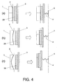
- FIG. 4 An alternative realization shown in figure 4 , is that the support of the closing wall has an elastic component (4) that permit the stress of the closing wall (3) not to exceed the elastic limit of the membrane.
- This elastic component (4) can be a spring, having one end connected to a fixed element (5), and another end fixed to the outer face of the closing wall (3), so that the closing wall is pressed against the membrane by the spring.
- the maximal stress applied by the spring should be lower than mechanical resistance of the membrane.
- the spring is located in the side of the closing wall (3), but in other embodiments the spring could also be located at the opposite side that is the side of the container and also pulling the closing wall against the membrane.
- the closing wall (3) is able to deform in order to adopt its shape to the membrane.
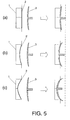
- the application of the wall can be performed in a progressive way as shown in figure 6 , in order to reduce but not stop the evaporation process.
- a regulation of the performance of the device can be obtained.
- figure 6 it can be observed that in the displacement of the closing wall, there is established a closed position ( figure 6d ) in which the membrane is completely covered by the closing wall, an open position ( figure 6a ) in which the membrane is in contact with the air, and an intermediate position ( figures 6b,6c ) in which the membrane is partially covered by the closing wall. Regulation of the degree of evaporation of the volatile substance is thereby achieved.
- a preferred embodiment of the invention as shown in figure 7 refers to an air-freshening device having a double cartridge.
- the device has two or more strips of vapour permeable material (2,2'), in which an air flow with a suitable temperature cooperates in the evaporation of two or more volatile substances, which comprises two or more containers (1,1') for at least two types of volatile substances in contact with said vapour permeable material (2,2'), which is exposed to said air flow.
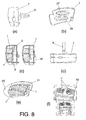
- the device also comprises a casing (7) (see figure 8 ) supporting said containers (1,1') and said vapour permeable strips (2,2'), and keeps them under the influence of said air flow.
- the device also has means (6) for selecting the volatile substances to be evaporated by means of allowing or stopping the air flow acting on either vapour permeable strip (2,2').
- Said means (6) for selecting the volatile substances may consist of two closure walls (3,3') interconnected, in such a way that when one wall is closing the corresponding permeable strip, the other wall is spaced apart from its corresponding permeable strip leaving the strip accessible.
- the two closing walls (3,3') defining the means (6) for selecting the volatile substances define an angle ( ⁇ ) in between and are interconnected at a pivoting point (8).
- the closing walls (3,3') are pivotally mounted in respect to the pivoting point (8) for selectively closing one of the permeable membranes (2,2').
- each closing wall (3,3') is also adapted to compensate possible deformation of the associated membrane (2,2'). In this case, this is achieved by a curved abutment or protuberance (39) provided in the inner face of the closing walls.
- Said air flow is preferably at a temperature suitable for enhancing the evaporation of said substances.
- Suitable temperature must be understood as any temperature having the effect of speeding up the degree of evaporation of the substances.
- vapour permeable strips are liquid impermeable evaporation membranes adhered to said containers (1,1') for the volatile substances forming an air-freshening unit, such that one of the faces of each strip is partially in direct contact with the respective volatile substance, and the other face is partially in direct contact with the environment.
- Volatile substances are preferably aromatic substances, although substances with another type of properties, such as insecticide substances for example, can also be used.
- the fragrance selection means (6) are placed between the air flow and the external face of the permeable strip.
- the device is complemented with means for fixing to a fixed structure (for example a hook (9) in figure 8 ), such as the grating of a ventilation air equipment outlet, for example, such as the ventilation air outlet of a motorized vehicle (10), or an air conditioning equipment.
- a fixed structure for example a hook (9) in figure 8
- a ventilation air equipment outlet for example, such as the ventilation air outlet of a motorized vehicle (10)
- an air conditioning equipment for example a fixed structure (for example a hook (9) in figure 8 ), such as the grating of a ventilation air equipment outlet, for example, such as the ventilation air outlet of a motorized vehicle (10), or an air conditioning equipment.
- the aforementioned air flow comes from the ventilation air outlet of a vehicle, or of an air conditioning equipment.
- the hook (9) allows to place the device in 0° to 360° position, with clicks in correspondence of some position (e.g. 0°, 45°, 90°, 135°, 180°).
- the invention provides an evaporator device of great simplicity, and therefore of a very reduced cost, is thus obtained, such that it can be used and disposed of, i.e. single use.
- the parts forming said casing (7) can be opened for the purpose of replacing the air-freshening unit (11) when the volatile has been consumed.
- the evaporator device comprises an air-freshening unit (11) formed by two independent containers (1,1') housing the volatile substances to be evaporated, which are preferably in a liquid state.
- the containers (1,1') are hermetically sealed by an evaporation membrane (2,2') such that each volatile substance is in direct contact with one majority part of the internal face of the respective membrane (2,2'), which is liquid impermeable such that it prevents any spillage, but is vapor permeable, therefore allowing the evaporation of the liquid it retains.
- the containers (1,1') are manufactured from a heat-formed plastic material.
- a protective strip (25) is arranged on the outer face of the membranes (2,2'), preventing the evaporation of the substance prior to using the device, for which purpose said strip is easily removable and partially extends outside of the device, forming a tab facilitating its removal after removing the front part for being able to access it.
- This protective strip (25) must be partially folded over itself and project on one side, such that the protective strip (25) can be easily removed from that side from the exterior of the product without needing to open the housing (7).
- the device comprises a housing (7) and a fragrance selector (26) formed by the double closing wall (3,3').
- the selector projects outside with a lever (similar to the knob 34 in figure 13 ) that allows to set the evaporation of substance A, or to set the evaporation of substance B, or to set an adjustable mixing of the two substances.
- a lever similar to the knob 34 in figure 13
- the inner part of the selector is placed between the air flow and the outer face of the permeable strips.
- the housing (7) is closed by snapping or differently coupling its upper part to its lower part or by other conventional means and the air-freshening unit (11) is enclosed inside the assembly, as seen in the figures.
- Said coupling can be stable, in which case the device will be a single-use device, i.e. to use and dispose of.
- the coupling can be removable so as to allow replacing the air-freshening unit with a spare part when the air-freshening liquid is used up.
- the front part of the housing (7) is provided with a holes (27,28) through which the containers (1,1') of the air-freshener unit (11) are visible.
- the containers can be transparent and the volatile substances housed therein can be coloured, for example with a colour associated to the aroma each of said substances releases.
- the device Since the device is especially indicated for use thereof under the influence of a hot air current, the materials with which it is manufactured, and particularly the materials of the containers (1,1'), have been carefully selected to withstand temperatures comprised between 75 and 80 °C.
- the surface of the selector (26) in contact with the permeable strip, or expected to be in contact with the permeable strip following user's actuation on the selector (26), is convex such that the surface of the selector can almost match the concave permeable strip in front of the respective container that lost its original planar shape during the use, due to pressure decrease inside the container following the evaporation of the liquid contained therein.
- the device comprises fixing means (9) for fixing it to a fixed structure, such as the grating (10) of the air outlet of a ventilation unit of a vehicle, as shown in figure 8f , such that the device is emerged in the air current generated, part of which passes through the device.
- fixing means (9) for fixing it to a fixed structure such as the grating (10) of the air outlet of a ventilation unit of a vehicle, as shown in figure 8f , such that the device is emerged in the air current generated, part of which passes through the device.
- the device could be applied on an air-conditioning equipment.
- the device is complemented with fixing means for fixing it on said grating, consisting in flexible tabs which, acting like a gripping device, can be stably coupled to said grating.
- the resilient tabs are integral to the intermediate part and pass through the rear part (8) through a hole, such that this intermediate part remains fixed during the adjustment and the rear part is the part which rotates to cause the adjustment.
- the evaporated product is diffused towards the sides of the device in 360°, for which purpose it has at least one side slot, and rear windows which allow the air current to enter or circulate impelling the evaporated product.
- a graduated scale allows the user to identify the degree of opening of the windows and therefore the degree of evaporation selected between a maximum and minimum for each fragrance.
- the device can be placed on a horizontal as well as vertical grating.
- the membrane adopts a transverse arrangement with regard to the feed direction of the air flow.
- said arrangement of the membrane could have a certain tilt with regard to the air flow.
- the evaporation surface of the membrane is also closed by applying a rigid flat wall against the membrane surface, however the movement of the wall is performed by an electromagnetic actuator (12).
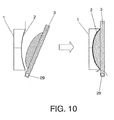
- the device of figure 9 comprises a casing (15) defining internally an air passage (14) wherein a fan (13) generates a forced current or air (17).
- the fan (13) is arranged at one end of the air passage (14), whereas at the other end of the passage (14) there is an opening (29) and an air-grid (19) located on said opening (29).
- a container (20) of a volatile substance with a membrane (21), is arranged at said opening so that the membrane receives the forced current or air (17).
- a closing wall (18) is provided for closing and opening said opening (29) so that to allow the membrane to receive the flow of air for the evaporation of the substance, or to close the membrane and avoid said evaporation.
- Said closing wall (18) is operated by a displacement element, in this case a solenoid or electromagnetic actuator (12) for closing and opening said opening (29).
- a displacement element in this case a solenoid or electromagnetic actuator (12) for closing and opening said opening (29).
- a cam element (23) is pivotally mounted on a shaft (22), and the closing wall (18) is joined to one part of the cam.
- the actuation element (25) of the electromagnetic actuator (12) is displaced to move the cam thus producing a pivoting movement of the closing wall about said shaft.
- the cam element (23) is biased by a return spring (16) connected to a fixed point (24).
- the closing wall (3) is arranged to move longitudinally along a longitudinal axis (A) of the membrane (2).
- the closing wall is displaced by means of a screw mechanism to move forward and backwards in respect to the membrane (2).
- the closing wall can be moved manually or by a suitable actuation mechanism.
- the closing wall (3) is housed within a cylinder (30) and it is screwed with the internal wall of said cylinder.
- the closing wall is arranged to move transversally in respect to the axis (A) of the membrane by means of an articulate quadrilateral.
- the closing wall is joined to the ends of first and a second arms(33,33') at a fist and second articulated points (31,31') at said closing wall.
- a second end (32,32') of said arms (33,33') are articulately joined to a fixed point. Therefore the closing wall is pivotally mounted in respect to the two articulation points (32,32').
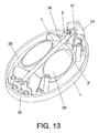
- the device of figures 13-15 comprises a double container having a first and second containers (1,1') protuding fron a common and flat plastic plate (37) which is fixed to the casing (7) of the device.
- the fragrance selection element (26) consist of a first closing wall (3) and a second closing wall (3') both joined to a pivoting point (8) defined by a straight rod (36).
- the walls (3,3') define an angle in between and in respect to said rod (36).
- the rod (36) is rotatably mounted on the casing (7) at its first and second ends (35,37), in such a manner that the first and second walls (3,3') are aranged to alternatively close one of the containers (1,1') as it can be more clearly observed on figure 15 .
- a knob (34) is joined to one end of the rod (36) and protudes outside of the casing (7), so that the user can manually rotate the rod (36) to close one the containers (1,1') by locating the corresponding closing wall in the entry of the container, thereby selecting the desired fragrance or product to be evaporated.
- Another aspect of the invention refers to a method for adjustably evaporating two volatile substances, which comprises putting said volatile substances into contact with two strips of vapor permeable material, respectively, and projecting an air flow on said strips, controlling the air flow acting on each strip and, as a result, the amount of each evaporated substance projected into the environment.
- Control of said air flow acting on said strip is carried out by modifying the area which the air flow must pass through before acting on each strip.
- Modification of the area for the passage of the air flow can be carried out by moving two parts, relatively to one another, making one part to cover each said strip by a greater or lesser extent thus decreasing or increasing the area available for the air flow.
- the degree of evaporation of the substance is also adjusted by means of controlling, either in a natural or forced manner, the temperature of the air flow.
Landscapes
- Life Sciences & Earth Sciences (AREA)
- Pest Control & Pesticides (AREA)
- Engineering & Computer Science (AREA)
- Health & Medical Sciences (AREA)
- General Health & Medical Sciences (AREA)
- Toxicology (AREA)
- Insects & Arthropods (AREA)
- Wood Science & Technology (AREA)
- Zoology (AREA)
- Environmental Sciences (AREA)
- Mechanical Engineering (AREA)
- Veterinary Medicine (AREA)
- Animal Behavior & Ethology (AREA)
- Public Health (AREA)
- Epidemiology (AREA)
- Chemical & Material Sciences (AREA)
- Combustion & Propulsion (AREA)
- General Engineering & Computer Science (AREA)
- Disinfection, Sterilisation Or Deodorisation Of Air (AREA)
- Catching Or Destruction (AREA)
- Percussion Or Vibration Massage (AREA)
- Acyclic And Carbocyclic Compounds In Medicinal Compositions (AREA)
- Beans For Foods Or Fodder (AREA)
- Medical Preparation Storing Or Oral Administration Devices (AREA)
- Registering, Tensioning, Guiding Webs, And Rollers Therefor (AREA)
- Gas Separation By Absorption (AREA)
- Closures For Containers (AREA)
- Electroluminescent Light Sources (AREA)
Applications Claiming Priority (2)
| Application Number | Priority Date | Filing Date | Title |
|---|---|---|---|
| US94258607P | 2007-06-07 | 2007-06-07 | |
| EP08760642A EP2155269B1 (fr) | 2007-06-07 | 2008-06-06 | Diffuseur de substance volatile |
Related Parent Applications (1)
| Application Number | Title | Priority Date | Filing Date |
|---|---|---|---|
| EP08760642.2 Division | 2008-06-06 |
Publications (2)
| Publication Number | Publication Date |
|---|---|
| EP2241337A1 true EP2241337A1 (fr) | 2010-10-20 |
| EP2241337B1 EP2241337B1 (fr) | 2013-05-15 |
Family
ID=39739810
Family Applications (2)
| Application Number | Title | Priority Date | Filing Date |
|---|---|---|---|
| EP10166097.5A Active EP2241337B1 (fr) | 2007-06-07 | 2008-06-06 | Dispositif de distribution d'une substance volatile |
| EP08760642A Active EP2155269B1 (fr) | 2007-06-07 | 2008-06-06 | Diffuseur de substance volatile |
Family Applications After (1)
| Application Number | Title | Priority Date | Filing Date |
|---|---|---|---|
| EP08760642A Active EP2155269B1 (fr) | 2007-06-07 | 2008-06-06 | Diffuseur de substance volatile |
Country Status (15)
| Country | Link |
|---|---|
| US (1) | US8062598B2 (fr) |
| EP (2) | EP2241337B1 (fr) |
| JP (1) | JP5680408B2 (fr) |
| CN (1) | CN101678138B (fr) |
| AT (1) | ATE506081T1 (fr) |
| AU (1) | AU2008258488A1 (fr) |
| BR (1) | BRPI0811632A2 (fr) |
| CA (1) | CA2687331C (fr) |
| DE (1) | DE602008006390D1 (fr) |
| ES (2) | ES2363110T3 (fr) |
| HK (1) | HK1134260A1 (fr) |
| MX (1) | MX2009012153A (fr) |
| PT (1) | PT2155269E (fr) |
| RU (1) | RU2482879C2 (fr) |
| WO (1) | WO2008148869A1 (fr) |
Families Citing this family (15)
| Publication number | Priority date | Publication date | Assignee | Title |
|---|---|---|---|---|
| WO2010090141A1 (fr) * | 2009-02-05 | 2010-08-12 | 株式会社ヴァレオサーマルシステムズ | Dispositif d'émission de parfum pour véhicule et composant d'étanchéité utilisé dans celui-ci |
| US8517351B2 (en) | 2011-04-28 | 2013-08-27 | S.C. Johnson & Son, Inc. | Centrifugal fan device |
| US8807538B2 (en) | 2011-04-28 | 2014-08-19 | S.C. Johnson & Son, Inc. | Centrifugal fan device |
| US20140091487A1 (en) * | 2012-10-02 | 2014-04-03 | David C. Belongia | Dispensing System |
| US9205165B2 (en) | 2012-10-22 | 2015-12-08 | S.C. Johnson & Son, Inc. | Volatile material dispensing system having an adjustable diffusion apparatus |
| US9327045B2 (en) * | 2013-10-22 | 2016-05-03 | American Covers, Inc. | Air freshener with porous membrane with leak pad and adjustable opening |
| US9603352B2 (en) * | 2014-03-31 | 2017-03-28 | S. C. Johnson & Son, Inc. | Dispenser |
| US10350968B2 (en) * | 2015-11-11 | 2019-07-16 | Ford Global Technologies Llc | Air vent register for a vehicle |
| US11077221B2 (en) | 2016-01-25 | 2021-08-03 | S. C. Johnson & Son, Inc. | Volatile dispenser for use in volatile dispensing systems |
| US10994042B2 (en) | 2016-01-25 | 2021-05-04 | S. C. Johnson & Son, Inc. | Heated air freshener |
| US10940226B2 (en) | 2016-03-01 | 2021-03-09 | S. C. Johnson & Son, Inc. | Dispenser |
| ES2672474B1 (es) * | 2016-12-13 | 2019-04-05 | Zobele Espana Sa | Dispositivo de evaporación de sustancias volátiles |
| CN109965489A (zh) * | 2017-12-27 | 2019-07-05 | 宁波香木町日用品有限公司 | 盛装容器及其应用 |
| RU185079U1 (ru) * | 2018-08-17 | 2018-11-21 | Владимир Генрихович Шапочкин | Устройство для распространения аромата |
| JP7403426B2 (ja) | 2020-10-14 | 2023-12-22 | 株式会社ホンダアクセス | 薬剤ユニットおよび車両 |
Citations (12)
| Publication number | Priority date | Publication date | Assignee | Title |
|---|---|---|---|---|
| US4268285A (en) * | 1980-02-11 | 1981-05-19 | Mason Engineering & Designing Corporation | Air freshening apparatus |
| JPH02252462A (ja) | 1989-03-28 | 1990-10-11 | Nippon Petrochem Co Ltd | 揮発性薬剤の揮散方法および薬剤揮散具 |
| EP0698355A1 (fr) | 1994-08-25 | 1996-02-28 | Ning Zhang | Fermoir rapide |
| US5575992A (en) | 1994-03-08 | 1996-11-19 | Waterbury Companies, Incorporated | Extended release hot and cold gel fragrance cartridges and method of making the same |
| WO1997042982A1 (fr) | 1996-05-14 | 1997-11-20 | S.C. Johnson & Son, Inc. | Dispositif disperseur de desodorisant |
| EP0923386A1 (fr) | 1996-06-28 | 1999-06-23 | S.C. Johnson & Son, Inc. | Dispositif servant a diffuser une substance de purification d'air et possedant une double cartouche |
| EP1082970A1 (fr) | 1999-09-07 | 2001-03-14 | General FIX S.R.L. | Réservoir permettant la libération des essences volatiles |
| WO2005014061A1 (fr) | 2003-07-24 | 2005-02-17 | Sarong Societa' Per Azioni | Recipient destine a diffuser des substances volatiles dans l'air ambiant |
| US20060032937A1 (en) * | 2004-08-13 | 2006-02-16 | Zobele Espana, S.A. | Container of active substances |
| WO2006084921A1 (fr) | 2005-02-03 | 2006-08-17 | Zobele España, S.A. | Diffuseur de substances volatiles a parfums multiples |
| EP1698355A1 (fr) | 2003-12-12 | 2006-09-06 | Zobele Espana, S.A. | Procede et dispositif pour l'evaporation par membrane de substances volatiles |
| WO2007048178A1 (fr) * | 2005-10-24 | 2007-05-03 | Intellectual Property Development Corporation Pty Ltd | Dispositifs de distribution |
Family Cites Families (4)
| Publication number | Priority date | Publication date | Assignee | Title |
|---|---|---|---|---|
| JPS5767746U (fr) * | 1980-10-07 | 1982-04-23 | ||
| US4361279A (en) * | 1980-11-03 | 1982-11-30 | The Clorox Company | Combined container and dispenser for volatile product |
| JPS62186861A (ja) * | 1986-02-12 | 1987-08-15 | 花王株式会社 | 芳香剤 |
| JP3817001B2 (ja) * | 1996-12-16 | 2006-08-30 | レンゴー株式会社 | 揮散性薬剤収納体 |
-
2008
- 2008-06-06 CA CA2687331A patent/CA2687331C/fr not_active Expired - Fee Related
- 2008-06-06 AU AU2008258488A patent/AU2008258488A1/en not_active Abandoned
- 2008-06-06 MX MX2009012153A patent/MX2009012153A/es active IP Right Grant
- 2008-06-06 WO PCT/EP2008/057069 patent/WO2008148869A1/fr active Application Filing
- 2008-06-06 CN CN2008800159932A patent/CN101678138B/zh not_active Expired - Fee Related
- 2008-06-06 PT PT08760642T patent/PT2155269E/pt unknown
- 2008-06-06 DE DE602008006390T patent/DE602008006390D1/de active Active
- 2008-06-06 ES ES08760642T patent/ES2363110T3/es active Active
- 2008-06-06 AT AT08760642T patent/ATE506081T1/de not_active IP Right Cessation
- 2008-06-06 RU RU2009141989/15A patent/RU2482879C2/ru not_active IP Right Cessation
- 2008-06-06 BR BRPI0811632-6A2A patent/BRPI0811632A2/pt active Search and Examination
- 2008-06-06 ES ES10166097T patent/ES2417858T3/es active Active
- 2008-06-06 EP EP10166097.5A patent/EP2241337B1/fr active Active
- 2008-06-06 EP EP08760642A patent/EP2155269B1/fr active Active
- 2008-06-06 JP JP2010510817A patent/JP5680408B2/ja active Active
- 2008-06-09 US US12/135,589 patent/US8062598B2/en active Active
-
2010
- 2010-03-02 HK HK10102248.4A patent/HK1134260A1/xx not_active IP Right Cessation
Patent Citations (13)
| Publication number | Priority date | Publication date | Assignee | Title |
|---|---|---|---|---|
| US4268285A (en) * | 1980-02-11 | 1981-05-19 | Mason Engineering & Designing Corporation | Air freshening apparatus |
| JPH02252462A (ja) | 1989-03-28 | 1990-10-11 | Nippon Petrochem Co Ltd | 揮発性薬剤の揮散方法および薬剤揮散具 |
| US5575992A (en) | 1994-03-08 | 1996-11-19 | Waterbury Companies, Incorporated | Extended release hot and cold gel fragrance cartridges and method of making the same |
| EP0698355A1 (fr) | 1994-08-25 | 1996-02-28 | Ning Zhang | Fermoir rapide |
| WO1997042982A1 (fr) | 1996-05-14 | 1997-11-20 | S.C. Johnson & Son, Inc. | Dispositif disperseur de desodorisant |
| EP0923386B1 (fr) | 1996-06-28 | 2001-08-22 | S.C. Johnson & Son, Inc. | Dispositif servant a diffuser une substance de purification d'air et possedant une double cartouche |
| EP0923386A1 (fr) | 1996-06-28 | 1999-06-23 | S.C. Johnson & Son, Inc. | Dispositif servant a diffuser une substance de purification d'air et possedant une double cartouche |
| EP1082970A1 (fr) | 1999-09-07 | 2001-03-14 | General FIX S.R.L. | Réservoir permettant la libération des essences volatiles |
| WO2005014061A1 (fr) | 2003-07-24 | 2005-02-17 | Sarong Societa' Per Azioni | Recipient destine a diffuser des substances volatiles dans l'air ambiant |
| EP1698355A1 (fr) | 2003-12-12 | 2006-09-06 | Zobele Espana, S.A. | Procede et dispositif pour l'evaporation par membrane de substances volatiles |
| US20060032937A1 (en) * | 2004-08-13 | 2006-02-16 | Zobele Espana, S.A. | Container of active substances |
| WO2006084921A1 (fr) | 2005-02-03 | 2006-08-17 | Zobele España, S.A. | Diffuseur de substances volatiles a parfums multiples |
| WO2007048178A1 (fr) * | 2005-10-24 | 2007-05-03 | Intellectual Property Development Corporation Pty Ltd | Dispositifs de distribution |
Also Published As
| Publication number | Publication date |
|---|---|
| WO2008148869A1 (fr) | 2008-12-11 |
| CN101678138A (zh) | 2010-03-24 |
| HK1134260A1 (en) | 2010-04-23 |
| BRPI0811632A2 (pt) | 2014-10-14 |
| US8062598B2 (en) | 2011-11-22 |
| EP2155269B1 (fr) | 2011-04-20 |
| ATE506081T1 (de) | 2011-05-15 |
| AU2008258488A1 (en) | 2008-12-11 |
| JP5680408B2 (ja) | 2015-03-04 |
| RU2009141989A (ru) | 2011-05-20 |
| DE602008006390D1 (de) | 2011-06-01 |
| MX2009012153A (es) | 2010-04-09 |
| US20080305002A1 (en) | 2008-12-11 |
| PT2155269E (pt) | 2011-06-28 |
| ES2363110T3 (es) | 2011-07-20 |
| EP2241337B1 (fr) | 2013-05-15 |
| CN101678138B (zh) | 2013-08-21 |
| RU2482879C2 (ru) | 2013-05-27 |
| CA2687331C (fr) | 2016-05-03 |
| CA2687331A1 (fr) | 2008-12-11 |
| JP2010528743A (ja) | 2010-08-26 |
| ES2417858T3 (es) | 2013-08-09 |
| EP2155269A1 (fr) | 2010-02-24 |
Similar Documents
| Publication | Publication Date | Title |
|---|---|---|
| EP2241337B1 (fr) | Dispositif de distribution d'une substance volatile | |
| EP1698355B1 (fr) | Dispositif pour l'evaporation par membrane de substances volatiles | |
| EP2455108B1 (fr) | Diffuseur de parfum | |
| EP2091574B1 (fr) | Dispositif d'évaporateur électrique de substances volatiles avec une intensité d'évaporation ajustable | |
| US5527493A (en) | Air treating device | |
| US6957779B2 (en) | Foldable, refillable, sustained-release fluid delivery system | |
| US20050185940A1 (en) | Controlable release of a volatile substance | |
| EP3452115B1 (fr) | Distributeur de composition volatile ayant une exposition à la membrane et une perte de poids de la composition volatile accrues | |
| US7597309B1 (en) | Constant-rate volatile material dispensing device | |
| EP2079488B1 (fr) | Dispositif évaporateur pour des substances volatiles | |
| CN106061317B (zh) | 处理头发的装置及相关的再填充器 | |
| WO2007019022A2 (fr) | Systeme d'administration de fluide a liberation prolongee, remplissable et pliable | |
| JPH10155404A (ja) | 2重開閉式薬剤蒸散機とカートリッジ | |
| JPH0735914U (ja) | 空調装置への蒸発性物質取付具 |
Legal Events
| Date | Code | Title | Description |
|---|---|---|---|
| PUAI | Public reference made under article 153(3) epc to a published international application that has entered the european phase |
Free format text: ORIGINAL CODE: 0009012 |
|
| AC | Divisional application: reference to earlier application |
Ref document number: 2155269 Country of ref document: EP Kind code of ref document: P |
|
| AK | Designated contracting states |
Kind code of ref document: A1 Designated state(s): AT BE BG CH CY CZ DE DK EE ES FI FR GB GR HR HU IE IS IT LI LT LU LV MC MT NL NO PL PT RO SE SI SK TR |
|
| AX | Request for extension of the european patent |
Extension state: AL BA MK RS |
|
| RIN1 | Information on inventor provided before grant (corrected) |
Inventor name: BERTASSI, EDOARDO Inventor name: MORENO PEREZ, DAVID Inventor name: MUNOZ MARTINEZ, JOSE Inventor name: MORHAIN, CEDRIC |
|
| 17P | Request for examination filed |
Effective date: 20110215 |
|
| 17Q | First examination report despatched |
Effective date: 20110713 |
|
| RIC1 | Information provided on ipc code assigned before grant |
Ipc: B60H 3/00 20060101ALI20121022BHEP Ipc: A01M 1/20 20060101ALI20121022BHEP Ipc: A61L 9/12 20060101AFI20121022BHEP |
|
| GRAP | Despatch of communication of intention to grant a patent |
Free format text: ORIGINAL CODE: EPIDOSNIGR1 |
|
| GRAS | Grant fee paid |
Free format text: ORIGINAL CODE: EPIDOSNIGR3 |
|
| GRAA | (expected) grant |
Free format text: ORIGINAL CODE: 0009210 |
|
| AC | Divisional application: reference to earlier application |
Ref document number: 2155269 Country of ref document: EP Kind code of ref document: P |
|
| AK | Designated contracting states |
Kind code of ref document: B1 Designated state(s): AT BE BG CH CY CZ DE DK EE ES FI FR GB GR HR HU IE IS IT LI LT LU LV MC MT NL NO PL PT RO SE SI SK TR |
|
| REG | Reference to a national code |
Ref country code: GB Ref legal event code: FG4D Ref country code: CH Ref legal event code: EP |
|
| REG | Reference to a national code |
Ref country code: AT Ref legal event code: REF Ref document number: 611800 Country of ref document: AT Kind code of ref document: T Effective date: 20130615 |
|
| REG | Reference to a national code |
Ref country code: IE Ref legal event code: FG4D |
|
| REG | Reference to a national code |
Ref country code: DE Ref legal event code: R096 Ref document number: 602008024672 Country of ref document: DE Effective date: 20130711 |
|
| REG | Reference to a national code |
Ref country code: ES Ref legal event code: FG2A Ref document number: 2417858 Country of ref document: ES Kind code of ref document: T3 Effective date: 20130809 |
|
| REG | Reference to a national code |
Ref country code: AT Ref legal event code: MK05 Ref document number: 611800 Country of ref document: AT Kind code of ref document: T Effective date: 20130515 |
|
| REG | Reference to a national code |
Ref country code: LT Ref legal event code: MG4D |
|
| REG | Reference to a national code |
Ref country code: NL Ref legal event code: VDEP Effective date: 20130515 |
|
| PG25 | Lapsed in a contracting state [announced via postgrant information from national office to epo] |
Ref country code: NO Free format text: LAPSE BECAUSE OF FAILURE TO SUBMIT A TRANSLATION OF THE DESCRIPTION OR TO PAY THE FEE WITHIN THE PRESCRIBED TIME-LIMIT Effective date: 20130815 Ref country code: SE Free format text: LAPSE BECAUSE OF FAILURE TO SUBMIT A TRANSLATION OF THE DESCRIPTION OR TO PAY THE FEE WITHIN THE PRESCRIBED TIME-LIMIT Effective date: 20130515 Ref country code: IS Free format text: LAPSE BECAUSE OF FAILURE TO SUBMIT A TRANSLATION OF THE DESCRIPTION OR TO PAY THE FEE WITHIN THE PRESCRIBED TIME-LIMIT Effective date: 20130915 Ref country code: GR Free format text: LAPSE BECAUSE OF FAILURE TO SUBMIT A TRANSLATION OF THE DESCRIPTION OR TO PAY THE FEE WITHIN THE PRESCRIBED TIME-LIMIT Effective date: 20130816 Ref country code: LT Free format text: LAPSE BECAUSE OF FAILURE TO SUBMIT A TRANSLATION OF THE DESCRIPTION OR TO PAY THE FEE WITHIN THE PRESCRIBED TIME-LIMIT Effective date: 20130515 Ref country code: AT Free format text: LAPSE BECAUSE OF FAILURE TO SUBMIT A TRANSLATION OF THE DESCRIPTION OR TO PAY THE FEE WITHIN THE PRESCRIBED TIME-LIMIT Effective date: 20130515 Ref country code: SI Free format text: LAPSE BECAUSE OF FAILURE TO SUBMIT A TRANSLATION OF THE DESCRIPTION OR TO PAY THE FEE WITHIN THE PRESCRIBED TIME-LIMIT Effective date: 20130515 Ref country code: PT Free format text: LAPSE BECAUSE OF FAILURE TO SUBMIT A TRANSLATION OF THE DESCRIPTION OR TO PAY THE FEE WITHIN THE PRESCRIBED TIME-LIMIT Effective date: 20130916 Ref country code: FI Free format text: LAPSE BECAUSE OF FAILURE TO SUBMIT A TRANSLATION OF THE DESCRIPTION OR TO PAY THE FEE WITHIN THE PRESCRIBED TIME-LIMIT Effective date: 20130515 |
|
| PG25 | Lapsed in a contracting state [announced via postgrant information from national office to epo] |
Ref country code: BG Free format text: LAPSE BECAUSE OF FAILURE TO SUBMIT A TRANSLATION OF THE DESCRIPTION OR TO PAY THE FEE WITHIN THE PRESCRIBED TIME-LIMIT Effective date: 20130815 Ref country code: HR Free format text: LAPSE BECAUSE OF FAILURE TO SUBMIT A TRANSLATION OF THE DESCRIPTION OR TO PAY THE FEE WITHIN THE PRESCRIBED TIME-LIMIT Effective date: 20130515 Ref country code: PL Free format text: LAPSE BECAUSE OF FAILURE TO SUBMIT A TRANSLATION OF THE DESCRIPTION OR TO PAY THE FEE WITHIN THE PRESCRIBED TIME-LIMIT Effective date: 20130515 |
|
| PG25 | Lapsed in a contracting state [announced via postgrant information from national office to epo] |
Ref country code: LV Free format text: LAPSE BECAUSE OF FAILURE TO SUBMIT A TRANSLATION OF THE DESCRIPTION OR TO PAY THE FEE WITHIN THE PRESCRIBED TIME-LIMIT Effective date: 20130515 |
|
| PG25 | Lapsed in a contracting state [announced via postgrant information from national office to epo] |
Ref country code: EE Free format text: LAPSE BECAUSE OF FAILURE TO SUBMIT A TRANSLATION OF THE DESCRIPTION OR TO PAY THE FEE WITHIN THE PRESCRIBED TIME-LIMIT Effective date: 20130515 Ref country code: BE Free format text: LAPSE BECAUSE OF FAILURE TO SUBMIT A TRANSLATION OF THE DESCRIPTION OR TO PAY THE FEE WITHIN THE PRESCRIBED TIME-LIMIT Effective date: 20130515 Ref country code: SK Free format text: LAPSE BECAUSE OF FAILURE TO SUBMIT A TRANSLATION OF THE DESCRIPTION OR TO PAY THE FEE WITHIN THE PRESCRIBED TIME-LIMIT Effective date: 20130515 Ref country code: CZ Free format text: LAPSE BECAUSE OF FAILURE TO SUBMIT A TRANSLATION OF THE DESCRIPTION OR TO PAY THE FEE WITHIN THE PRESCRIBED TIME-LIMIT Effective date: 20130515 Ref country code: DK Free format text: LAPSE BECAUSE OF FAILURE TO SUBMIT A TRANSLATION OF THE DESCRIPTION OR TO PAY THE FEE WITHIN THE PRESCRIBED TIME-LIMIT Effective date: 20130515 |
|
| REG | Reference to a national code |
Ref country code: CH Ref legal event code: PL |
|
| PG25 | Lapsed in a contracting state [announced via postgrant information from national office to epo] |
Ref country code: MC Free format text: LAPSE BECAUSE OF FAILURE TO SUBMIT A TRANSLATION OF THE DESCRIPTION OR TO PAY THE FEE WITHIN THE PRESCRIBED TIME-LIMIT Effective date: 20130515 Ref country code: NL Free format text: LAPSE BECAUSE OF FAILURE TO SUBMIT A TRANSLATION OF THE DESCRIPTION OR TO PAY THE FEE WITHIN THE PRESCRIBED TIME-LIMIT Effective date: 20130515 Ref country code: RO Free format text: LAPSE BECAUSE OF FAILURE TO SUBMIT A TRANSLATION OF THE DESCRIPTION OR TO PAY THE FEE WITHIN THE PRESCRIBED TIME-LIMIT Effective date: 20130515 |
|
| PLBE | No opposition filed within time limit |
Free format text: ORIGINAL CODE: 0009261 |
|
| STAA | Information on the status of an ep patent application or granted ep patent |
Free format text: STATUS: NO OPPOSITION FILED WITHIN TIME LIMIT |
|
| REG | Reference to a national code |
Ref country code: IE Ref legal event code: MM4A |
|
| 26N | No opposition filed |
Effective date: 20140218 |
|
| PG25 | Lapsed in a contracting state [announced via postgrant information from national office to epo] |
Ref country code: IE Free format text: LAPSE BECAUSE OF NON-PAYMENT OF DUE FEES Effective date: 20130606 Ref country code: LI Free format text: LAPSE BECAUSE OF NON-PAYMENT OF DUE FEES Effective date: 20130630 Ref country code: CH Free format text: LAPSE BECAUSE OF NON-PAYMENT OF DUE FEES Effective date: 20130630 |
|
| REG | Reference to a national code |
Ref country code: DE Ref legal event code: R097 Ref document number: 602008024672 Country of ref document: DE Effective date: 20140218 |
|
| PG25 | Lapsed in a contracting state [announced via postgrant information from national office to epo] |
Ref country code: MT Free format text: LAPSE BECAUSE OF FAILURE TO SUBMIT A TRANSLATION OF THE DESCRIPTION OR TO PAY THE FEE WITHIN THE PRESCRIBED TIME-LIMIT Effective date: 20130515 |
|
| PG25 | Lapsed in a contracting state [announced via postgrant information from national office to epo] |
Ref country code: TR Free format text: LAPSE BECAUSE OF FAILURE TO SUBMIT A TRANSLATION OF THE DESCRIPTION OR TO PAY THE FEE WITHIN THE PRESCRIBED TIME-LIMIT Effective date: 20130515 Ref country code: CY Free format text: LAPSE BECAUSE OF FAILURE TO SUBMIT A TRANSLATION OF THE DESCRIPTION OR TO PAY THE FEE WITHIN THE PRESCRIBED TIME-LIMIT Effective date: 20130515 |
|
| PG25 | Lapsed in a contracting state [announced via postgrant information from national office to epo] |
Ref country code: HU Free format text: LAPSE BECAUSE OF FAILURE TO SUBMIT A TRANSLATION OF THE DESCRIPTION OR TO PAY THE FEE WITHIN THE PRESCRIBED TIME-LIMIT; INVALID AB INITIO Effective date: 20080606 Ref country code: LU Free format text: LAPSE BECAUSE OF NON-PAYMENT OF DUE FEES Effective date: 20130606 |
|
| REG | Reference to a national code |
Ref country code: FR Ref legal event code: PLFP Year of fee payment: 9 |
|
| PGFP | Annual fee paid to national office [announced via postgrant information from national office to epo] |
Ref country code: DE Payment date: 20160622 Year of fee payment: 9 |
|
| REG | Reference to a national code |
Ref country code: FR Ref legal event code: PLFP Year of fee payment: 10 |
|
| REG | Reference to a national code |
Ref country code: DE Ref legal event code: R119 Ref document number: 602008024672 Country of ref document: DE |
|
| PG25 | Lapsed in a contracting state [announced via postgrant information from national office to epo] |
Ref country code: DE Free format text: LAPSE BECAUSE OF NON-PAYMENT OF DUE FEES Effective date: 20180103 |
|
| REG | Reference to a national code |
Ref country code: FR Ref legal event code: PLFP Year of fee payment: 11 |
|
| P01 | Opt-out of the competence of the unified patent court (upc) registered |
Effective date: 20230520 |
|
| PGFP | Annual fee paid to national office [announced via postgrant information from national office to epo] |
Ref country code: FR Payment date: 20230614 Year of fee payment: 16 |
|
| PGFP | Annual fee paid to national office [announced via postgrant information from national office to epo] |
Ref country code: IT Payment date: 20230623 Year of fee payment: 16 Ref country code: GB Payment date: 20230529 Year of fee payment: 16 Ref country code: ES Payment date: 20230705 Year of fee payment: 16 |