EP2241237A2 - Embout d'aspiration, aspirateur et son procédé de fonctionnement - Google Patents
Embout d'aspiration, aspirateur et son procédé de fonctionnement Download PDFInfo
- Publication number
- EP2241237A2 EP2241237A2 EP10401041A EP10401041A EP2241237A2 EP 2241237 A2 EP2241237 A2 EP 2241237A2 EP 10401041 A EP10401041 A EP 10401041A EP 10401041 A EP10401041 A EP 10401041A EP 2241237 A2 EP2241237 A2 EP 2241237A2
- Authority
- EP
- European Patent Office
- Prior art keywords
- suction attachment
- sensor
- drive
- vacuum cleaner
- suction
- Prior art date
- Legal status (The legal status is an assumption and is not a legal conclusion. Google has not performed a legal analysis and makes no representation as to the accuracy of the status listed.)
- Withdrawn
Links
Images


Classifications
-
- A—HUMAN NECESSITIES
- A47—FURNITURE; DOMESTIC ARTICLES OR APPLIANCES; COFFEE MILLS; SPICE MILLS; SUCTION CLEANERS IN GENERAL
- A47L—DOMESTIC WASHING OR CLEANING; SUCTION CLEANERS IN GENERAL
- A47L9/00—Details or accessories of suction cleaners, e.g. mechanical means for controlling the suction or for effecting pulsating action; Storing devices specially adapted to suction cleaners or parts thereof; Carrying-vehicles specially adapted for suction cleaners
- A47L9/02—Nozzles
- A47L9/04—Nozzles with driven brushes or agitators
- A47L9/0405—Driving means for the brushes or agitators
- A47L9/0411—Driving means for the brushes or agitators driven by electric motor
-
- A—HUMAN NECESSITIES
- A47—FURNITURE; DOMESTIC ARTICLES OR APPLIANCES; COFFEE MILLS; SPICE MILLS; SUCTION CLEANERS IN GENERAL
- A47L—DOMESTIC WASHING OR CLEANING; SUCTION CLEANERS IN GENERAL
- A47L9/00—Details or accessories of suction cleaners, e.g. mechanical means for controlling the suction or for effecting pulsating action; Storing devices specially adapted to suction cleaners or parts thereof; Carrying-vehicles specially adapted for suction cleaners
- A47L9/02—Nozzles
- A47L9/04—Nozzles with driven brushes or agitators
- A47L9/0461—Dust-loosening tools, e.g. agitators, brushes
- A47L9/0466—Rotating tools
- A47L9/0477—Rolls
Definitions
- the invention relates to a vacuum cleaner for a vacuum cleaner according to the preamble of claim 1.
- the invention further relates to a vacuum cleaner with such a suction attachment and a method for driving such a suction attachment.
- Suction attachments for vacuum cleaners are well known.
- Such Saugvora are often referred to as a floor nozzle and can be a rotating bristle roller, as in DE 689 05 252 T2 or the DE 103 57 497 A1 described include.
- Such bristle rollers are driven electrically or by suction turbine.
- Suction attachments modern vacuum cleaner are designed for optimal dust absorption, so that due to a high suction capacity of the vacuum cleaner, especially on carpets or carpets, a comparatively large force (pushing force) is required for the movement of the suction attachment.
- a comparatively large force is required for the movement of the suction attachment.
- Such sliding forces arise because the suction attachment is strongly pressed against the carpet due to the negative pressure generated by the vacuum cleaner.
- the force required for the movement of the suction attachment is dependent on the suction power of the cleaner, the nature of the substrate, the suction attachment or the like.
- the suction attachment comprises a driven bristle roller for processing the substrate to be cleaned, movement of the suction attachment in an opposite direction to the direction of the brush roller rotation requires additional force.
- the invention is therefore an object of the invention to provide a suction with very good dust holding capacity and low, required sliding forces.
- the suction attachment for a vacuum cleaner comprises at least one rotatable bristle roller.
- the suction attachment comprises an electric motor drive with at least one rotatable drive drive and a motor, wherein the suction attachment is movable based on a sensed thrust.
- a suction attachment thus assists a user by reducing the thrust force to be expended by the user, namely by having the travel drive operative to move the suction attachment in the direction predetermined by the user.
- the thrust force expended by the user is then reduced by the contribution due to the travel drive. This reduction can go so far that a nearly powerless movement of the suction attachment, especially on carpet or carpets, is possible. This is also the case when the suction attachment is provided and designed for optimum dust absorption.
- a user can advantageously maintain his work habits, since the suction attachment based on the sensed thrust force is movable and thus an adjustment of the travel drive to a user-desired feed rate, feed direction or the like is ensured.
- the vacuum cleaner comprises at least one processing unit for controlling the motor of the traction drive based on the sensed thrust. If the vacuum cleaner comprises the processing unit, the vacuum cleaner attachment is particularly inexpensive to produce and easy to replace.
- the object is achieved by a method for driving a suction attachment as described above and in the following.
- a difference of a sensed thrust force and a Saugvorsatz thrust of the electric motor driven Saugvorsatzes is determined and the difference is adjusted by changing drive parameters, in particular the direction of rotation and / or rotational speed of the electric motor drive to a predetermined or predetermined value. It is thus detected a user desired movement and / or speed and implemented by the suction intent in an actual movement and / or speed.
- an expended on a very good suction suction device reduces a user expended thrust and increases user comfort.
- the latter comprises at least as a sensor for the thrust force a sensor by means of which a change in position of displaceable parts of the suction attachment and / or a vacuum cleaner tube can be determined.
- the sensor may be comprised of a vacuum cleaner tube, so that by means of the Sensors a change in position of movable parts of the vacuum cleaner attachment, vacuum cleaner tube and / or vacuum cleaner can be determined.
- the sensor for detecting a change in position of the vacuum cleaner attachment and / or vacuum cleaner tube may be provided and formed in space. The sensor outputs a signal correlated with a user-initiated force. In operation, this is received and processed by a processing unit which controls or regulates the electromotive drive on the basis of the signal.
- the sensor is arranged for example in the region of a pivot point of a Saugrohrstutzens the Saugvorsatzes and detects directly or indirectly forces between the suction attachment and the suction tube, z. B.
- the sensor can be arranged on a bracket of the pivot point or the Saugrohrstutzens.
- the sensor can be arranged in or on a handle, in particular handle of the vacuum cleaner tube. Then the sensor detects forces acting on the handle or a change of position of the handle in space. So z. B. pressed in a forward stroke of the handle relative to a rest position down or pulled in the return stroke of the handle relative to the rest position up.
- the rest position can also be a previous position.
- a switch As preferred embodiments of the sensor, a switch, a strain gauge, piezoelectric element, pressure-sensitive resistor, capacitive or inductive sensor, Hall sensor or magnetoresistive sensor and the like come into consideration. If the sensor is a switch, then results in dependence on a feed by the user, ie z. For example, when the operator pushes the suction attachment forward or pulls back, an actuation of the switch. In addition or alternatively, the switch can be provided and designed for actuation by the user.
- Is the sensor a magnetic field sensor, z.
- a Hall sensor or magnetoresistive sensor it results in a force application, a change in a sensed by the sensor magnetic field, for example, when a ferromagnetic material or a magnet is moved relative to the actual sensor.
- a varying inductance can be sensed directly or indirectly by moving a ferromagnetic material or magnet relative to the coil so as to induce an evaluable voltage, change a resonant frequency of the coil, or the like.
- a differential transformer is particularly suitable for this purpose.
- a feed rate of the suction intent is predetermined or predetermined. At a predetermined feed rate this z. B. 0.5 m / s. However, other suitable feed rates are possible. Alternatively, a fine-step or continuous adjustment of the feed rate to a desired feed rate possible. In this case, the feed rate of the suction attachment can be adapted to the sensed thrust.
- the engine and the drive are directly coupled.
- the suction attachment may comprise an electrical circuit for reversing the direction of rotation of the motor.
- the engine and the travel drive can be coupled indirectly, for example by means of a transmission and / or a belt connection. In this case, the direction of rotation of the traction drive can be effected by means of an intervention in the transmission.
- the motor is preferably a brushless motor, so that for the Saugvorsatz overall associated with brushless motors benefits, namely long life of the engine and low maintenance due to the absence of brushes, regardless of the load almost constant speed, high speed capability and give a short-term overloadability.
- the suction attachment comprises as drive at least one roller, a crawler, at least two wheels or the like.
- at least two wheels at least one of the wheels can be driven by means of the electromotive drive.
- the or each wheel can be designed so that a good grip on different surfaces, especially different types of carpets or carpets, guaranteed.
- the or each wheel may have a rough tread.
- at least the running surface may comprise a material which has particularly good adhesive properties on the substrate.
- the suction attachment comprises a bristle roller drive for rotating the bristle rollers in a direction opposite to the direction of rotation of the travel drive.
- a bristle roller drive for rotating the bristle rollers in a direction opposite to the direction of rotation of the travel drive.
- the motor is provided for driving both the bristle roller and the traction drive.
- the motor is provided for driving both the bristle roller and the traction drive.
- a single motor drives both parts, as well as a reduction in weight and a reduction of a construction volume of the suction attachment.
- a "mechanics" introduced per area and time is independent of a working speed of a user. This results in a guarantee of constant cleaning results, regardless of the feed rate; a user who moves the suction attachment quickly achieves the same cleaning performance as a user who moves the suction attachment more slowly.
- the substrate, in particular flooring, spared because the bristle roller in the case of a stoppage of the traction drive also stops.
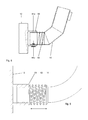
- FIG. 8 attachment of the sensor, ie at the transition between suction 12 and intake manifold 18, additionally or alternatively, the attachment of a sensor 44a, 44b, as in FIG. 8 shown, in principle also at other positions between suction attachment 12 and base unit 28, in particular between suction attachment 12 and handle 24 into consideration.
- FIG. 10 two mutually movably arranged (telescopic) pipe sections 66, 68, which are combined by means of a spring connection 60 shown only in terms of their functionality as a spring. In operation, a relative movement between the pipe sections 66, 68 as well as a relative movement between the in FIG. 8 components are sensed.
- the spring 60 which is replaced in a practical embodiment by a functionally equivalent spring element 62, thereby counteracting a force introduced by the user and prevents a virtually independent of the size of the introduced force relative movement of the pipe sections 66, 68 to each other.
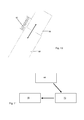
- FIG. 11 shows schematically greatly simplified the context in the control of the drive 16 based on a sensed thrust.
- the sensor 44 For sensing the thrust of the sensor 44 is provided (instead of the automatic sensor 44 shown may also be a switch 56 ( FIG. 4 ) as a manual sensor).
- the sensor 44 outputs a signal correlated with the user-initiated thrust force to a processing unit 70, the z. B. from Saugabsatz 12, from the handle 24 or from the base unit 28 may be included.
- the processing unit 70 generates based on the signal received from the sensor 44, a signal for controlling the traction drive 16.
- the signal for controlling the traction drive 16 may be a signal that causes only a reversal of direction of the traction drive 16, ie a binary signal which a forward or Reverse operation of the traction drive 16 coded.
- the signal generated by the processing unit 70 may also be an analog signal or a bit pattern that encodes both the direction of rotation and a speed of the traction drive 16.
- Specified is a suction attachment 12 for a vacuum cleaner 10, wherein the suction attachment 12 comprises at least one rotatable bristle roller 14 and wherein the suction attachment 12 is movable with a rotatable drive 16 based on a sensed thrust, a vacuum cleaner 10 with such Suction attachment 12 and with at least one processing unit 70 for controlling the motor 40 and a method for driving such a suction attachment 12th
Landscapes
- Engineering & Computer Science (AREA)
- Mechanical Engineering (AREA)
- Nozzles For Electric Vacuum Cleaners (AREA)
Applications Claiming Priority (1)
| Application Number | Priority Date | Filing Date | Title |
|---|---|---|---|
| DE200910017120 DE102009017120A1 (de) | 2009-04-15 | 2009-04-15 | Saugvorsatz, Staubsauger und Verfahren zum Antrieb |
Publications (2)
| Publication Number | Publication Date |
|---|---|
| EP2241237A2 true EP2241237A2 (fr) | 2010-10-20 |
| EP2241237A3 EP2241237A3 (fr) | 2012-06-20 |
Family
ID=42289032
Family Applications (1)
| Application Number | Title | Priority Date | Filing Date |
|---|---|---|---|
| EP10401041A Withdrawn EP2241237A3 (fr) | 2009-04-15 | 2010-04-01 | Embout d'aspiration, aspirateur et son procédé de fonctionnement |
Country Status (2)
| Country | Link |
|---|---|
| EP (1) | EP2241237A3 (fr) |
| DE (1) | DE102009017120A1 (fr) |
Families Citing this family (2)
| Publication number | Priority date | Publication date | Assignee | Title |
|---|---|---|---|---|
| DE102016010775A1 (de) | 2016-09-08 | 2018-03-08 | Sven Templin | Positionierungsassistiertes handgeführtes Gerät |
| DE202016005473U1 (de) | 2016-09-08 | 2017-12-11 | Sven Templin | Positionierungsassistiertes handgeführtes Gerät |
Family Cites Families (7)
| Publication number | Priority date | Publication date | Assignee | Title |
|---|---|---|---|---|
| US4347643A (en) * | 1981-01-23 | 1982-09-07 | The Singer Company | Power assist drive upright vacuum cleaner and power assist drive system therefor |
| JPH0815470B2 (ja) | 1988-07-22 | 1996-02-21 | 松下電器産業株式会社 | 電気掃除機 |
| EP0930840B1 (fr) * | 1997-08-11 | 2005-12-14 | Koninklijke Philips Electronics N.V. | Aspirateur avec buse d'aspiration et organes d'entrainement electriques reglables |
| JP2002058623A (ja) * | 2000-08-16 | 2002-02-26 | Masaya Hara | 電気掃除機 |
| KR100531224B1 (ko) | 2003-06-09 | 2005-11-28 | 삼성광주전자 주식회사 | 터빈브러시 |
| US7725223B2 (en) * | 2003-09-30 | 2010-05-25 | Techtronic Floor Care Technology Limited | Control arrangement for a propulsion unit for a self-propelled floor care appliance |
| KR100635823B1 (ko) * | 2005-04-01 | 2006-10-19 | 엘지전자 주식회사 | 직립형 진공청소기의 주행 제어용 그립 |
-
2009
- 2009-04-15 DE DE200910017120 patent/DE102009017120A1/de not_active Withdrawn
-
2010
- 2010-04-01 EP EP10401041A patent/EP2241237A3/fr not_active Withdrawn
Also Published As
| Publication number | Publication date |
|---|---|
| EP2241237A3 (fr) | 2012-06-20 |
| DE102009017120A1 (de) | 2010-10-28 |
Similar Documents
| Publication | Publication Date | Title |
|---|---|---|
| DE19653161C2 (de) | Fernsteuerbarer, automatisch verfahrbarer Staubsauger | |
| DE69821659T2 (de) | Reinigungsroboter | |
| DE60111306T2 (de) | Bürstenkopfpositioniervorrichtung | |
| EP3569124B1 (fr) | Appareil de nettoyage | |
| EP2245974B1 (fr) | Procédé d'opération d'un appareil adaptable pour un aspirateur et appareil adaptable correspondant | |
| DE102005046639A1 (de) | Selbständig verfahrbares Bodenstaub-Aufsammelgerät | |
| DE102004014252A1 (de) | Verfahren zum Betreiben eines Staubsaugers mit einer Saugdüse sowie Staubsauger mit einer Saugdüse | |
| DE102008061251A1 (de) | Elektrischer Staubsauger und Verfahren zu dessen Betrieb | |
| DE29913775U1 (de) | Gerät zur Bodenpflege, insbesondere Staubsauger | |
| EP2615959B1 (fr) | Système d'entraînement pour un dispositif de nettoyage et dispositiv de nettoyage | |
| EP2241237A2 (fr) | Embout d'aspiration, aspirateur et son procédé de fonctionnement | |
| DE10309621A1 (de) | Motorgetriebenes, handgeführtes Transportfahrzeug mit intuitiver Haltegriffsteuerung | |
| WO2000079058A1 (fr) | Unite de nettoyage | |
| DE102011013913B3 (de) | Steckverbinderkombination, deren Verwendung sowie Verfahren zur Steuerung der Steck- und Ziehkraft eines Steckers | |
| DE102015102333B4 (de) | Kehrmaschine und Verfahren zum Nachstellen einer Kehrwalze einer Kehrmaschine | |
| EP3417756B1 (fr) | Machine de nettoyage du sol dotée d'un réglage d'appui de brosse | |
| DE102015114082A1 (de) | Saugroboter mit rotierender Borstwalze und Verfahren zum Reinigen einer Borstwalze eines Saugroboters | |
| EP4275567B1 (fr) | Machine de nettoyage de sol et procédé de fonctionnement d'une machine de nettoyage de sol | |
| EP1072727A2 (fr) | Véhicule et procédé pour nettoyer les surfaces | |
| EP3973837B1 (fr) | Aspirateur pourvu de tête de traitement | |
| EP4098166B1 (fr) | Buse pour sol pour aspirateurs, aspirateur, ensemble de brosses rotatives et procédé permettant de faire fonctionner un aspirateur | |
| DE102021207321B4 (de) | Antriebseinheit für einen Bodenroboter | |
| DE102009001513A1 (de) | Fahrzeug zur Unterstützung einer auf eine Fortbewegung des Fahrzeugs gerichteten Krafteinwirkung eines Nutzers | |
| DE102019210971B4 (de) | Fahrbarer Reinigungsroboter | |
| DE102017123572B4 (de) | Handgeführte Transporthilfsvorrichtung |
Legal Events
| Date | Code | Title | Description |
|---|---|---|---|
| PUAI | Public reference made under article 153(3) epc to a published international application that has entered the european phase |
Free format text: ORIGINAL CODE: 0009012 |
|
| AK | Designated contracting states |
Kind code of ref document: A2 Designated state(s): AT BE BG CH CY CZ DE DK EE ES FI FR GB GR HR HU IE IS IT LI LT LU LV MC MK MT NL NO PL PT RO SE SI SK SM TR |
|
| AX | Request for extension of the european patent |
Extension state: AL BA ME RS |
|
| PUAL | Search report despatched |
Free format text: ORIGINAL CODE: 0009013 |
|
| AK | Designated contracting states |
Kind code of ref document: A3 Designated state(s): AT BE BG CH CY CZ DE DK EE ES FI FR GB GR HR HU IE IS IT LI LT LU LV MC MK MT NL NO PL PT RO SE SI SK SM TR |
|
| AX | Request for extension of the european patent |
Extension state: AL BA ME RS |
|
| RIC1 | Information provided on ipc code assigned before grant |
Ipc: A47L 9/04 20060101AFI20120515BHEP Ipc: A47L 9/28 20060101ALI20120515BHEP |
|
| STAA | Information on the status of an ep patent application or granted ep patent |
Free format text: STATUS: THE APPLICATION IS DEEMED TO BE WITHDRAWN |
|
| 18D | Application deemed to be withdrawn |
Effective date: 20121221 |