EP2241237A2 - Suction header, vacuum cleaner and method for driving same - Google Patents
Suction header, vacuum cleaner and method for driving same Download PDFInfo
- Publication number
- EP2241237A2 EP2241237A2 EP10401041A EP10401041A EP2241237A2 EP 2241237 A2 EP2241237 A2 EP 2241237A2 EP 10401041 A EP10401041 A EP 10401041A EP 10401041 A EP10401041 A EP 10401041A EP 2241237 A2 EP2241237 A2 EP 2241237A2
- Authority
- EP
- European Patent Office
- Prior art keywords
- suction attachment
- sensor
- drive
- vacuum cleaner
- suction
- Prior art date
- Legal status (The legal status is an assumption and is not a legal conclusion. Google has not performed a legal analysis and makes no representation as to the accuracy of the status listed.)
- Withdrawn
Links
Images


Classifications
-
- A—HUMAN NECESSITIES
- A47—FURNITURE; DOMESTIC ARTICLES OR APPLIANCES; COFFEE MILLS; SPICE MILLS; SUCTION CLEANERS IN GENERAL
- A47L—DOMESTIC WASHING OR CLEANING; SUCTION CLEANERS IN GENERAL
- A47L9/00—Details or accessories of suction cleaners, e.g. mechanical means for controlling the suction or for effecting pulsating action; Storing devices specially adapted to suction cleaners or parts thereof; Carrying-vehicles specially adapted for suction cleaners
- A47L9/02—Nozzles
- A47L9/04—Nozzles with driven brushes or agitators
- A47L9/0405—Driving means for the brushes or agitators
- A47L9/0411—Driving means for the brushes or agitators driven by electric motor
-
- A—HUMAN NECESSITIES
- A47—FURNITURE; DOMESTIC ARTICLES OR APPLIANCES; COFFEE MILLS; SPICE MILLS; SUCTION CLEANERS IN GENERAL
- A47L—DOMESTIC WASHING OR CLEANING; SUCTION CLEANERS IN GENERAL
- A47L9/00—Details or accessories of suction cleaners, e.g. mechanical means for controlling the suction or for effecting pulsating action; Storing devices specially adapted to suction cleaners or parts thereof; Carrying-vehicles specially adapted for suction cleaners
- A47L9/02—Nozzles
- A47L9/04—Nozzles with driven brushes or agitators
- A47L9/0461—Dust-loosening tools, e.g. agitators, brushes
- A47L9/0466—Rotating tools
- A47L9/0477—Rolls
Definitions
- the invention relates to a vacuum cleaner for a vacuum cleaner according to the preamble of claim 1.
- the invention further relates to a vacuum cleaner with such a suction attachment and a method for driving such a suction attachment.
- Suction attachments for vacuum cleaners are well known.
- Such Saugvora are often referred to as a floor nozzle and can be a rotating bristle roller, as in DE 689 05 252 T2 or the DE 103 57 497 A1 described include.
- Such bristle rollers are driven electrically or by suction turbine.
- Suction attachments modern vacuum cleaner are designed for optimal dust absorption, so that due to a high suction capacity of the vacuum cleaner, especially on carpets or carpets, a comparatively large force (pushing force) is required for the movement of the suction attachment.
- a comparatively large force is required for the movement of the suction attachment.
- Such sliding forces arise because the suction attachment is strongly pressed against the carpet due to the negative pressure generated by the vacuum cleaner.
- the force required for the movement of the suction attachment is dependent on the suction power of the cleaner, the nature of the substrate, the suction attachment or the like.
- the suction attachment comprises a driven bristle roller for processing the substrate to be cleaned, movement of the suction attachment in an opposite direction to the direction of the brush roller rotation requires additional force.
- the invention is therefore an object of the invention to provide a suction with very good dust holding capacity and low, required sliding forces.
- the suction attachment for a vacuum cleaner comprises at least one rotatable bristle roller.
- the suction attachment comprises an electric motor drive with at least one rotatable drive drive and a motor, wherein the suction attachment is movable based on a sensed thrust.
- a suction attachment thus assists a user by reducing the thrust force to be expended by the user, namely by having the travel drive operative to move the suction attachment in the direction predetermined by the user.
- the thrust force expended by the user is then reduced by the contribution due to the travel drive. This reduction can go so far that a nearly powerless movement of the suction attachment, especially on carpet or carpets, is possible. This is also the case when the suction attachment is provided and designed for optimum dust absorption.
- a user can advantageously maintain his work habits, since the suction attachment based on the sensed thrust force is movable and thus an adjustment of the travel drive to a user-desired feed rate, feed direction or the like is ensured.
- the vacuum cleaner comprises at least one processing unit for controlling the motor of the traction drive based on the sensed thrust. If the vacuum cleaner comprises the processing unit, the vacuum cleaner attachment is particularly inexpensive to produce and easy to replace.
- the object is achieved by a method for driving a suction attachment as described above and in the following.
- a difference of a sensed thrust force and a Saugvorsatz thrust of the electric motor driven Saugvorsatzes is determined and the difference is adjusted by changing drive parameters, in particular the direction of rotation and / or rotational speed of the electric motor drive to a predetermined or predetermined value. It is thus detected a user desired movement and / or speed and implemented by the suction intent in an actual movement and / or speed.
- an expended on a very good suction suction device reduces a user expended thrust and increases user comfort.
- the latter comprises at least as a sensor for the thrust force a sensor by means of which a change in position of displaceable parts of the suction attachment and / or a vacuum cleaner tube can be determined.
- the sensor may be comprised of a vacuum cleaner tube, so that by means of the Sensors a change in position of movable parts of the vacuum cleaner attachment, vacuum cleaner tube and / or vacuum cleaner can be determined.
- the sensor for detecting a change in position of the vacuum cleaner attachment and / or vacuum cleaner tube may be provided and formed in space. The sensor outputs a signal correlated with a user-initiated force. In operation, this is received and processed by a processing unit which controls or regulates the electromotive drive on the basis of the signal.
- the sensor is arranged for example in the region of a pivot point of a Saugrohrstutzens the Saugvorsatzes and detects directly or indirectly forces between the suction attachment and the suction tube, z. B.
- the sensor can be arranged on a bracket of the pivot point or the Saugrohrstutzens.
- the sensor can be arranged in or on a handle, in particular handle of the vacuum cleaner tube. Then the sensor detects forces acting on the handle or a change of position of the handle in space. So z. B. pressed in a forward stroke of the handle relative to a rest position down or pulled in the return stroke of the handle relative to the rest position up.
- the rest position can also be a previous position.
- a switch As preferred embodiments of the sensor, a switch, a strain gauge, piezoelectric element, pressure-sensitive resistor, capacitive or inductive sensor, Hall sensor or magnetoresistive sensor and the like come into consideration. If the sensor is a switch, then results in dependence on a feed by the user, ie z. For example, when the operator pushes the suction attachment forward or pulls back, an actuation of the switch. In addition or alternatively, the switch can be provided and designed for actuation by the user.
- Is the sensor a magnetic field sensor, z.
- a Hall sensor or magnetoresistive sensor it results in a force application, a change in a sensed by the sensor magnetic field, for example, when a ferromagnetic material or a magnet is moved relative to the actual sensor.
- a varying inductance can be sensed directly or indirectly by moving a ferromagnetic material or magnet relative to the coil so as to induce an evaluable voltage, change a resonant frequency of the coil, or the like.
- a differential transformer is particularly suitable for this purpose.
- a feed rate of the suction intent is predetermined or predetermined. At a predetermined feed rate this z. B. 0.5 m / s. However, other suitable feed rates are possible. Alternatively, a fine-step or continuous adjustment of the feed rate to a desired feed rate possible. In this case, the feed rate of the suction attachment can be adapted to the sensed thrust.
- the engine and the drive are directly coupled.
- the suction attachment may comprise an electrical circuit for reversing the direction of rotation of the motor.
- the engine and the travel drive can be coupled indirectly, for example by means of a transmission and / or a belt connection. In this case, the direction of rotation of the traction drive can be effected by means of an intervention in the transmission.
- the motor is preferably a brushless motor, so that for the Saugvorsatz overall associated with brushless motors benefits, namely long life of the engine and low maintenance due to the absence of brushes, regardless of the load almost constant speed, high speed capability and give a short-term overloadability.
- the suction attachment comprises as drive at least one roller, a crawler, at least two wheels or the like.
- at least two wheels at least one of the wheels can be driven by means of the electromotive drive.
- the or each wheel can be designed so that a good grip on different surfaces, especially different types of carpets or carpets, guaranteed.
- the or each wheel may have a rough tread.
- at least the running surface may comprise a material which has particularly good adhesive properties on the substrate.
- the suction attachment comprises a bristle roller drive for rotating the bristle rollers in a direction opposite to the direction of rotation of the travel drive.
- a bristle roller drive for rotating the bristle rollers in a direction opposite to the direction of rotation of the travel drive.
- the motor is provided for driving both the bristle roller and the traction drive.
- the motor is provided for driving both the bristle roller and the traction drive.
- a single motor drives both parts, as well as a reduction in weight and a reduction of a construction volume of the suction attachment.
- a "mechanics" introduced per area and time is independent of a working speed of a user. This results in a guarantee of constant cleaning results, regardless of the feed rate; a user who moves the suction attachment quickly achieves the same cleaning performance as a user who moves the suction attachment more slowly.
- the substrate, in particular flooring, spared because the bristle roller in the case of a stoppage of the traction drive also stops.
- FIG. 8 attachment of the sensor, ie at the transition between suction 12 and intake manifold 18, additionally or alternatively, the attachment of a sensor 44a, 44b, as in FIG. 8 shown, in principle also at other positions between suction attachment 12 and base unit 28, in particular between suction attachment 12 and handle 24 into consideration.
- FIG. 10 two mutually movably arranged (telescopic) pipe sections 66, 68, which are combined by means of a spring connection 60 shown only in terms of their functionality as a spring. In operation, a relative movement between the pipe sections 66, 68 as well as a relative movement between the in FIG. 8 components are sensed.
- the spring 60 which is replaced in a practical embodiment by a functionally equivalent spring element 62, thereby counteracting a force introduced by the user and prevents a virtually independent of the size of the introduced force relative movement of the pipe sections 66, 68 to each other.
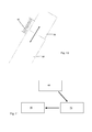
- FIG. 11 shows schematically greatly simplified the context in the control of the drive 16 based on a sensed thrust.
- the sensor 44 For sensing the thrust of the sensor 44 is provided (instead of the automatic sensor 44 shown may also be a switch 56 ( FIG. 4 ) as a manual sensor).
- the sensor 44 outputs a signal correlated with the user-initiated thrust force to a processing unit 70, the z. B. from Saugabsatz 12, from the handle 24 or from the base unit 28 may be included.
- the processing unit 70 generates based on the signal received from the sensor 44, a signal for controlling the traction drive 16.
- the signal for controlling the traction drive 16 may be a signal that causes only a reversal of direction of the traction drive 16, ie a binary signal which a forward or Reverse operation of the traction drive 16 coded.
- the signal generated by the processing unit 70 may also be an analog signal or a bit pattern that encodes both the direction of rotation and a speed of the traction drive 16.
- Specified is a suction attachment 12 for a vacuum cleaner 10, wherein the suction attachment 12 comprises at least one rotatable bristle roller 14 and wherein the suction attachment 12 is movable with a rotatable drive 16 based on a sensed thrust, a vacuum cleaner 10 with such Suction attachment 12 and with at least one processing unit 70 for controlling the motor 40 and a method for driving such a suction attachment 12th
Landscapes
- Engineering & Computer Science (AREA)
- Mechanical Engineering (AREA)
- Nozzles For Electric Vacuum Cleaners (AREA)
Abstract
Angegeben wird ein Saugvorsatz (12) für einen Staubsauger (10), wobei der Saugvorsatz (12) zumindest eine drehbare Borstenwalze (14) umfasst und wobei der Saugvorsatz (12) mit einem drehbaren Fahrantrieb (16) auf Basis einer sensierten Schubkraft bewegbar ist, ein Staubsauger (10) mit einem solchen Saugvorsatz (12) und mit zumindest einer Verarbeitungseinheit (70) zur Ansteuerung des Motors (40) sowie ein Verfahren zum Antrieb eines solchen Saugvorsatzes (12).Disclosed is a suction attachment (12) for a vacuum cleaner (10), wherein the suction attachment (12) comprises at least one rotatable bristle roller (14) and wherein the suction attachment (12) is movable with a rotatable travel drive (16) based on a sensed thrust force, a vacuum cleaner (10) with such a suction attachment (12) and with at least one processing unit (70) for controlling the motor (40) and a method for driving such a suction attachment (12).
Description
Saugvorsatz, Staubsauger und Verfahren zum AntriebSuction attachment, vacuum cleaner and method of driving
Die Erfindung betrifft einen Saugvorsatz für einen Staubsauger gemäß dem Oberbegriff des Anspruchs 1. Die Erfindung betrifft weiter einen Staubsauger mit einem solchen Saugvorsatz sowie ein Verfahren zum Antrieb eines solchen Saugvorsatzes.The invention relates to a vacuum cleaner for a vacuum cleaner according to the preamble of claim 1. The invention further relates to a vacuum cleaner with such a suction attachment and a method for driving such a suction attachment.
Saugvorsätze für Staubsauger, insbesondere Bodenstaubsauger, sind allgemein bekannt. Solche Saugvorsätze werden häufig als Bodendüse bezeichnet und können eine rotierende Borstenwalze, wie in der
Saugvorsätze moderner Bodenstaubsauger sind in der Regel für eine optimale Staubaufnahme ausgelegt, so dass aufgrund einer hohen Saugleistung des Bodenstaubsaugers insbesondere auf Teppichen oder Teppichböden ein vergleichsweise großer Kraftaufwand (Schiebekraft) für die Bewegung des Saugvorsatzes erforderlich ist. Solche Schiebekräfte ergeben sich, da der Saugvorsatz aufgrund des vom Staubsauger erzeugten Unterdrucks stark an den Teppich angedrückt wird. Die für die Bewegung des Saugvorsatzes nötige Kraft ist dabei abhängig von der Saugleistung des Saugers, Beschaffenheit des Untergrunds, des Saugvorsatzes oder dergleichen. Wenn der Saugvorsatz eine angetriebene Borstenwalze zur Bearbeitung des zu reinigenden Untergrunds umfasst, erfordert eine Bewegung des Saugvorsatzes in eine der Borstenwalzendrehrichtung entgegengesetzte Richtung zusätzlichen Kraftaufwand.Suction attachments modern vacuum cleaner are designed for optimal dust absorption, so that due to a high suction capacity of the vacuum cleaner, especially on carpets or carpets, a comparatively large force (pushing force) is required for the movement of the suction attachment. Such sliding forces arise because the suction attachment is strongly pressed against the carpet due to the negative pressure generated by the vacuum cleaner. The force required for the movement of the suction attachment is dependent on the suction power of the cleaner, the nature of the substrate, the suction attachment or the like. When the suction attachment comprises a driven bristle roller for processing the substrate to be cleaned, movement of the suction attachment in an opposite direction to the direction of the brush roller rotation requires additional force.
Soll bei Saugvorsätzen eine Reduktion der erforderlichen Kraft - Schiebekraft - erfolgen, geschieht dies in der Regel auf Kosten einer Staubaufnahmeleistung durch gezielte Undichtigkeiten im System.If a reduction of the required force - pushing force - is to be carried out with suction attachments, this is usually done at the expense of a dust absorption capacity through targeted leaks in the system.
Der Erfindung liegt daher die Aufgabe zugrunde, einen Saugvorsatz mit sehr guter Staubaufnahmefähigkeit und niedrigen, erforderlichen Schiebekräften anzugeben.The invention is therefore an object of the invention to provide a suction with very good dust holding capacity and low, required sliding forces.
Diese Aufgabe wird erfindungsgemäß gelöst mit den Merkmalen des Anspruchs 1. Der Saugvorsatz für einen Staubsauger umfasst zumindest eine drehbare Borstenwalze. Zudem umfasst der Saugvorsatz einen elektromotorischen Antrieb mit zumindest einem drehbaren Fahrantrieb und einem Motor, wobei der Saugvorsatz auf Basis einer sensierten Schubkraft bewegbar ist. Ein derartiger Saugvorsatz unterstützt somit einen Benutzer, indem die vom Benutzer aufzuwendende Schubkraft reduziert wird, nämlich indem der Fahrantrieb zur Bewegung des Saugvorsatzes in die vom Benutzer vorgegebene Richtung wirksam ist. Die vom Benutzer aufzuwendende Schubkraft reduziert sich dann um den Beitrag aufgrund des Fahrantriebs. Diese Reduktion kann soweit gehen, dass eine nahezu kraftlose Bewegung des Saugvorsatzes, insbesondere über Teppich oder Teppichböden, möglich ist. Dies ist auch der Fall, wenn der Saugvorsatz zur optimalen Staubaufnahme vorgesehen und ausgebildet ist.This object is achieved according to the invention with the features of claim 1. The suction attachment for a vacuum cleaner comprises at least one rotatable bristle roller. In addition, the suction attachment comprises an electric motor drive with at least one rotatable drive drive and a motor, wherein the suction attachment is movable based on a sensed thrust. Such a suction attachment thus assists a user by reducing the thrust force to be expended by the user, namely by having the travel drive operative to move the suction attachment in the direction predetermined by the user. The The thrust force expended by the user is then reduced by the contribution due to the travel drive. This reduction can go so far that a nearly powerless movement of the suction attachment, especially on carpet or carpets, is possible. This is also the case when the suction attachment is provided and designed for optimum dust absorption.
Ein Benutzer kann vorteilhaft seine Arbeitsgewohnheiten beibehalten, da der Saugvorsatz auf Basis der sensierten Schubkraft bewegbar ist und somit eine Anpassung des Fahrantriebs an eine vom Benutzer gewünschte Vorschubgeschwindigkeit, Vorschubrichtung oder dergleichen gewährleistet ist.A user can advantageously maintain his work habits, since the suction attachment based on the sensed thrust force is movable and thus an adjustment of the travel drive to a user-desired feed rate, feed direction or the like is ensured.
Die Aufgabe wird weiterhin gelöst mit einem Staubsauger wie vorhergehend und im Folgenden beschrieben. Dabei umfasst der Staubsauger zumindest eine Verarbeitungseinheit zur Ansteuerung des Motors des Fahrantriebs auf Basis der sensierten Schubkraft. Wenn der Staubsauger die Verarbeitungseinheit umfasst, ist der Staubsaugervorsatz besonders günstig herstellbar und einfach austauschbar.The object is further achieved with a vacuum cleaner as previously and described below. In this case, the vacuum cleaner comprises at least one processing unit for controlling the motor of the traction drive based on the sensed thrust. If the vacuum cleaner comprises the processing unit, the vacuum cleaner attachment is particularly inexpensive to produce and easy to replace.
Des Weiteren wird die Aufgabe gelöst durch ein Verfahren zum Antrieb eines Saugvorsatzes wie vorhergehend und im Folgenden beschrieben. Dazu ist vorgesehen, dass eine Differenz einer sensierten Schubkraft und einer Saugvorsatz-Schubkraft des elektromotorisch angetriebenen Saugvorsatzes ermittelt wird und die Differenz mittels Änderung von Antriebsparametern, insbesondere von Drehrichtung und/oder Drehgeschwindigkeit, des elektromotorischen Antriebs an einen vorgegebenen oder vorgebbaren Wert angepasst wird. Es wird also eine vom Benutzer gewünschte Bewegung und/oder Geschwindigkeit erkannt und vom Saugvorsatz in eine tatsächliche Bewegung und/oder Geschwindigkeit umgesetzt. Hierdurch werden bei einem auf sehr gute Saugleistung ausgerichteten Saugvorsatz eine vom Benutzer aufzuwendende Schubkraft reduziert und ein Nutzerkomfort erhöht.Furthermore, the object is achieved by a method for driving a suction attachment as described above and in the following. For this purpose, it is provided that a difference of a sensed thrust force and a Saugvorsatz thrust of the electric motor driven Saugvorsatzes is determined and the difference is adjusted by changing drive parameters, in particular the direction of rotation and / or rotational speed of the electric motor drive to a predetermined or predetermined value. It is thus detected a user desired movement and / or speed and implemented by the suction intent in an actual movement and / or speed. As a result, an expended on a very good suction suction device reduces a user expended thrust and increases user comfort.
Vorteilhafte Ausgestaltungen der Erfindung sind Gegenstand der Unteransprüche. Dabei verwendete Rückbeziehungen weisen auf die weitere Ausbildung des Gegenstandes des Hauptanspruches durch die Merkmale des jeweiligen Unteranspruches hin; sie sind nicht als ein Verzicht auf die Erzielung eines selbständigen, gegenständlichen Schutzes für die Merkmalskombinationen der rückbezogenen Unteransprüche zu verstehen. Des Weiteren ist im Hinblick auf eine Auslegung der Ansprüche bei einer näheren Konkretisierung eines Merkmals in einem nachgeordneten Anspruch davon auszugehen, dass eine derartige Beschränkung in den jeweils vorangehenden Ansprüchen nicht vorhanden ist.Advantageous embodiments of the invention are the subject of the dependent claims. This used backlinks point to the further development of the subject matter of the main claim by the features of the respective subclaim; they should not be construed as a waiver of obtaining independent, objective protection for the feature combinations of the dependent claims. Furthermore, with a view to an interpretation of the claims in a closer specification of a feature in a subordinate claim, it is to be assumed that such a restriction does not exist in the respective preceding claims.
In einer bevorzugten Ausführungsform des Saugvorsatzes umfasst dieser zumindest als Sensor für die Schubkraft einen Sensor, mittels welchem eine Positionsänderung verschieblicher Teile des Saugvorsatzes und/oder eines Staubsaugerrohrs ermittelbar ist. Alternativ kann der Sensor von einem Staubsaugerrohr umfasst sein, so dass mittels des Sensors eine Positionsänderung verschieblicher Teile des Staubsaugervorsatzes, Staubsaugerrohrs und/oder Staubsaugers ermittelbar ist. Zudem oder alternativ kann der Sensor zur Erfassung einer Positionsänderung des Staubsaugervorsatzes und/oder Staubsaugerrohrs im Raum vorgesehen und ausgebildet sein. Der Sensor gibt ein mit einer vom Benutzer eingeleiteten Kraft korrelliertes Signal aus. Dieses wird im Betrieb von einer Verarbeitungseinheit empfangen und verarbeitet, welche auf Basis des Signals den elektromotorischen Antrieb steuert oder regelt.In a preferred embodiment of the suction attachment, the latter comprises at least as a sensor for the thrust force a sensor by means of which a change in position of displaceable parts of the suction attachment and / or a vacuum cleaner tube can be determined. Alternatively, the sensor may be comprised of a vacuum cleaner tube, so that by means of the Sensors a change in position of movable parts of the vacuum cleaner attachment, vacuum cleaner tube and / or vacuum cleaner can be determined. Additionally or alternatively, the sensor for detecting a change in position of the vacuum cleaner attachment and / or vacuum cleaner tube may be provided and formed in space. The sensor outputs a signal correlated with a user-initiated force. In operation, this is received and processed by a processing unit which controls or regulates the electromotive drive on the basis of the signal.
Der Sensor ist beispielsweise im Bereich eines Drehpunktes eines Saugrohrstutzens des Saugvorsatzes angeordnet und erfasst direkt oder indirekt Kräfte zwischen dem Saugvorsatz und dem Saugrohr, z. B. kann der Sensor an eine Halterung des Drehpunktes oder des Saugrohrstutzens angeordnet sein. Alternativ kann der Sensor in einem oder an einem Handgriff, insbesondere Handgriff des Staubsaugerrohrs, angeordnet sein. Dann erfasst der Sensor auf den Handgriff wirkende Kräfte oder eine Positionsänderung des Handgriffs im Raum. So wird z. B. in einem Vorwärtshub der Handgriff relativ zu einer Ruheposition nach unten gedrückt oder im Rückwärtshub der Handgriff relativ zur Ruheposition nach oben gezogen. Die Ruheposition kann dabei auch eine vorhergehende Position sein.The sensor is arranged for example in the region of a pivot point of a Saugrohrstutzens the Saugvorsatzes and detects directly or indirectly forces between the suction attachment and the suction tube, z. B. the sensor can be arranged on a bracket of the pivot point or the Saugrohrstutzens. Alternatively, the sensor can be arranged in or on a handle, in particular handle of the vacuum cleaner tube. Then the sensor detects forces acting on the handle or a change of position of the handle in space. So z. B. pressed in a forward stroke of the handle relative to a rest position down or pulled in the return stroke of the handle relative to the rest position up. The rest position can also be a previous position.
Als bevorzugte Ausführungsformen des Sensors kommen ein Schalter, ein Dehnungsmessstreifen, Piezoelement, druckempfindlicher Widerstand, kapazitiver oder induktiver Sensor, Hallsensor oder magnetoresistiver Sensor und dergleichen in Betracht. Ist der Sensor ein Schalter, so ergibt sich in Abhängigkeit von einem Vorschub durch den Benutzer, also z. B. wenn der Bediener den Saugvorsatz nach vorne schiebt oder nach hinten zieht, eine Betätigung des Schalters. Zudem oder alternativ kann der Schalter zur Betätigung durch den Benutzer vorgesehen und ausgebildet sein.As preferred embodiments of the sensor, a switch, a strain gauge, piezoelectric element, pressure-sensitive resistor, capacitive or inductive sensor, Hall sensor or magnetoresistive sensor and the like come into consideration. If the sensor is a switch, then results in dependence on a feed by the user, ie z. For example, when the operator pushes the suction attachment forward or pulls back, an actuation of the switch. In addition or alternatively, the switch can be provided and designed for actuation by the user.
Ist der Sensor ein Magnetfeldsensor, z. B. ein Hallsensor oder magnetoresistiver Sensor, so ergibt sich bei einer Krafteinleitung eine Änderung in einem von dem Sensor sensierten Magnetfeld, wenn beispielsweise ein ferromagnetisches Material oder ein Magnet relativ zum eigentlichen Sensor bewegt wird.Is the sensor a magnetic field sensor, z. As a Hall sensor or magnetoresistive sensor, it results in a force application, a change in a sensed by the sensor magnetic field, for example, when a ferromagnetic material or a magnet is moved relative to the actual sensor.
Ist der Sensor eine Spule, kann eine sich ändernde Induktivität direkt oder indirekt sensiert werden, indem ein ferromagnetisches Material oder ein Magnet relativ zur Spule bewegt wird, um so eine auswertbare Spannung zu induzieren, eine Resonanzfrequenz der Spule zu ändern oder dergleichen. Besonders geeignet ist dazu ein Differentialtransformator.If the sensor is a coil, a varying inductance can be sensed directly or indirectly by moving a ferromagnetic material or magnet relative to the coil so as to induce an evaluable voltage, change a resonant frequency of the coil, or the like. Particularly suitable for this purpose is a differential transformer.
In einer bevorzugten Ausführungsform ist eine Vorschubgeschwindigkeit des Saugvorsatzes vorgegeben oder vorgebbar. Bei einer vorgegebenen Vorschubgeschwindigkeit kann diese z. B. 0,5 m/s betragen. Es sind jedoch auch andere geeignete Vorschubgeschwindigkeiten möglich. Alternativ ist eine feinstufige oder stufenlose Anpassung der Vorschubgeschwindigkeit an eine gewünschte Vorschubgeschwindigkeit möglich. Dabei kann die Vorschubgeschwindigkeit des Saugvorsatzes an die sensierte Schubkraft angepasst werden.In a preferred embodiment, a feed rate of the suction intent is predetermined or predetermined. At a predetermined feed rate this z. B. 0.5 m / s. However, other suitable feed rates are possible. Alternatively, a fine-step or continuous adjustment of the feed rate to a desired feed rate possible. In this case, the feed rate of the suction attachment can be adapted to the sensed thrust.
In einer bevorzugten Ausführungsform sind der Motor und der Fahrantrieb direkt koppelbar. Zudem kann der Saugvorsatz eine elektrische Schaltung zur Drehrichtungsumschaltung des Motors umfassen. Alternativ sind der Motor und der Fahrantrieb indirekt, beispielsweise mittels eines Getriebes und/oder einer Riemenverbindung koppelbar. Dabei kann die Drehrichtungsumkehr des Fahrantriebs mittels eines Eingriffs in das Getriebe erfolgen.In a preferred embodiment, the engine and the drive are directly coupled. In addition, the suction attachment may comprise an electrical circuit for reversing the direction of rotation of the motor. Alternatively, the engine and the travel drive can be coupled indirectly, for example by means of a transmission and / or a belt connection. In this case, the direction of rotation of the traction drive can be effected by means of an intervention in the transmission.
Der Motor ist bevorzugt ein bürstenloser Motor, so dass sich für den Saugvorsatz insgesamt die mit bürstenlosen Motoren verbundenen Vorteile, nämlich lange Lebensdauer des Motors und Wartungsarmut aufgrund der nicht vorhandenen Bürsten, eine unabhängig von der Belastung nahezu konstante Drehzahl, eine Tauglichkeit für hohe Drehzahlen und eine kurzzeitige Überlastbarkeit ergeben. Die Tatsache, dass zur Versorgung solcher bürstenloser Motoren drei Leiter erforderlich sind, erweist sich in Bezug auf die fallweise erforderliche Drehrichtungsumkehr ebenfalls als Vorteil, weil bei einem solchen so genannten Drehstromantrieb bekanntlich eine Umschaltung zweier Phasen für eine Drehrichtungsumkehr ausreicht.The motor is preferably a brushless motor, so that for the Saugvorsatz overall associated with brushless motors benefits, namely long life of the engine and low maintenance due to the absence of brushes, regardless of the load almost constant speed, high speed capability and give a short-term overloadability. The fact that three conductors are required to supply such brushless motors, also proves to be an advantage with respect to the occasionally required direction reversal, because in such a so-called three-phase drive is known to switch two phases sufficient for a reversal of direction.
In einer bevorzugten Ausführungsform umfasst der Saugvorsatz als Fahrantrieb zumindest eine Walze, eine Raupenkette, zumindest zwei Räder oder dergleichen. Bei zumindest zwei Rädern ist zumindest eines der Räder mittels des elektromotorischen Antriebs antreibbar. Das oder jedes Rad kann derart ausgeführt sein, dass ein guter Halt auf unterschiedlichen Untergründen, insbesondere verschiedenen Arten von Teppichen oder Teppichböden, gewährleistet ist. Zum Beispiel kann das oder jedes Rad eine grobstollige Lauffläche aufweisen. Zudem oder alternativ kann zumindest die Lauffläche ein Material aufweisen, welches besonders gute Hafteigenschaften auf dem Untergrund aufweist.In a preferred embodiment, the suction attachment comprises as drive at least one roller, a crawler, at least two wheels or the like. With at least two wheels, at least one of the wheels can be driven by means of the electromotive drive. The or each wheel can be designed so that a good grip on different surfaces, especially different types of carpets or carpets, guaranteed. For example, the or each wheel may have a rough tread. In addition or alternatively, at least the running surface may comprise a material which has particularly good adhesive properties on the substrate.
In einer weiteren bevorzugten Ausführungsform umfasst der Saugvorsatz einen Borstenwalzen-Antrieb zur Drehung der Borstenwalzen in einer der Drehrichtung des Fahrantriebs entgegengesetzten Richtung. Dies bedingt eine besonders effiziente Reinigung, da, wenn die Borstenwalze entgegen der Bewegungsrichtung des Saugvorsatzes rotiert, eine "höhere Mechanik" in den Untergrund, insbesondere den Bodenbelag, eingebracht wird. Hierdurch werden besonders viel Staub und Schmutz gelöst und aufgewirbelt und so die Staubaufnahme verbessert. Besonders bevorzugt ist die Drehrichtung der Borstenwalze in Abhängigkeit von der Drehrichtung des Fahrantriebs umkehrbar. Dabei gleicht der Fahrantrieb eine von der Borstenwalze erzeugte Bewegung des Saugvorsatzes ganz oder teilweise aus, so dass ein hoher Benutzerkomfort gewährleistet ist.In a further preferred embodiment, the suction attachment comprises a bristle roller drive for rotating the bristle rollers in a direction opposite to the direction of rotation of the travel drive. This requires a particularly efficient cleaning, since, when the bristle roller rotates counter to the direction of movement of the suction attachment, a "higher mechanics" in the substrate, especially the flooring, is introduced. As a result, a lot of dust and dirt are dissolved and stirred up, thus improving the dust absorption. Particularly preferably, the direction of rotation of the bristle roller is reversible depending on the direction of rotation of the traction drive. In this case, the travel drive compensates for a movement of the suction attachment generated by the bristle roller completely or partially, so that a high level of user comfort is ensured.
In einer weiteren bevorzugten Ausführungsform ist der Motor zum Antrieb sowohl der Borstenwalze als auch des Fahrantriebs vorgesehen. Hierdurch ergibt sich eine Kostenreduzierung, da ein einziger Motor beide Teile antreibt, sowie eine Gewichtsreduktion und eine Verringerung eines Bauvolumens des Saugvorsatzes. Zudem ist, da die Umdrehungen der Borstenwalze und die Drehung des Fahrantriebs gekoppelt sind, eine pro Fläche und Zeit eingebrachte "Mechanik" unabhängig von einer Arbeitsgeschwindigkeit eines Nutzers. Hierdurch ergibt sich eine Gewährleistung konstanter Reinigungsergebnisse, unabhängig von der Vorschubgeschwindigkeit; ein Benutzer, welcher den Saugvorsatz schnell bewegt, erzielt die gleiche Reinigungsleistung wie ein Benutzer, welcher den Saugvorsatz langsamer bewegt. Zudem wird der Untergrund, insbesondere Bodenbelag, geschont, da die Borstenwalze im Falle eines Stillstands des Fahrantriebs ebenfalls stillsteht.In a further preferred embodiment, the motor is provided for driving both the bristle roller and the traction drive. This results in a cost reduction, since a single motor drives both parts, as well as a reduction in weight and a reduction of a construction volume of the suction attachment. In addition, since the rotations of the bristle roller and the rotation of the traction drive are coupled, a "mechanics" introduced per area and time is independent of a working speed of a user. This results in a guarantee of constant cleaning results, regardless of the feed rate; a user who moves the suction attachment quickly achieves the same cleaning performance as a user who moves the suction attachment more slowly. In addition, the substrate, in particular flooring, spared because the bristle roller in the case of a stoppage of the traction drive also stops.
Nachfolgend wird ein Ausführungsbeispiel der Erfindung anhand der Zeichnung näher erläutert. Einander entsprechende Gegenstände oder Elemente sind in allen Figuren mit den gleichen Bezugszeichen versehen.An embodiment of the invention will be explained in more detail with reference to the drawing. Corresponding objects or elements are provided in all figures with the same reference numerals.
Das oder jedes Ausführungsbeispiel ist nicht als Einschränkung der Erfindung zu verstehen. Vielmehr sind im Rahmen der vorliegenden Offenbarung zahlreiche Abänderungen und Modifikationen möglich, insbesondere solche Varianten, Elemente und Kombinationen und/oder Materialien, die zum Beispiel durch Kombination oder Abwandlung von einzelnen in Verbindung mit den im allgemeinen oder speziellen Beschreibungsteil beschriebenen sowie in den Ansprüchen und/oder der Zeichnung enthaltenen Merkmalen bzw. Elementen oder Verfahrensschritten für den Fachmann im Hinblick auf die Lösung der Aufgabe entnehmbar sind und durch kombinierbare Merkmale zu einem neuen Gegenstand oder zu neuen Verfahrensschritten bzw. Verfahrensschrittfolgen führen.The or each embodiment is not to be understood as limiting the invention. Rather, numerous modifications and variations are possible within the scope of the present disclosure, in particular those variants, elements and combinations and / or materials which may be described, for example, by combination or modification of particulars described in the general or specific description and in the claims and / or features contained in the drawing or elements or method steps for a person skilled in the art with regard to the solution of the task can be removed and lead by combinable features to a new subject or to new process steps or procedural steps.
Darin zeigen
- Figur 1
- einen Staubsauger mit einer Ausführungsform eines erfindungsgemäßen Saugvorsatzes in Seitenansicht,
- Figur 2
- eine Ausführungsform eines erfindungsgemäßen Saugvorsatzes im Querschnitt,
- Figur 3
- eine alternative Ausführungsform eines erfindungsgemäßen Saugvorsatzes im Querschnitt,
- Figur 4
- einen Sensor in einem Staubsauger-Handgriff im Querschnitt,
- Figur 5
- eine Ausführungsform des Sensors aus
Figur 4 dargestellt in einer Draufsicht, - Figur 6
- eine weitere Ausführungsform eines Sensors in einem Staubsauger-Handgriff im Querschnitt,
- Figur 7
- einen Sensor in einem Ansaugstutzen im Querschnitt,
- Figur 8
- eine alternative Ausführungsform eines Sensors an einem Ansaugstutzen im Querschnitt,
- Figur 9
- eine Ausführungsform eines geeigneten Ansaugstutzens im Querschnitt,
Figur 10- eine Ausführungsform eines geeigneten Anbringteils für einen Sensor im Querschnitt und
- Figur 11
- ein Blockdiagramm zur Veranschaulichung des Wirkzusammenhangs bei der erfindungsgemäßen Ansteuerung des Saugvorsatzes.
-
Figur 1 zeigt eine schematisch vereinfachte Darstellung eines Staubsaugers 10 mit einer Ausführungsform eines erfindungsgemäßen Saugvorsatzes 12 in Seitenansicht.Der Saugvorsatz 12umfasst eine Borstenwalze 14 sowie einen drehbaren Fahrantrieb 16 und ist mittels eines Ansaugstutzens 18mit einem Staubsaugerrohr 20 desStaubsaugers 10 gekoppelt.Das Staubsaugerrohr 20 umfasst an einem oberen Ende 22einen Handgriff 24.Der Staubsaugerschlauch 26 ist wiederummit einem Basisgerät 28 verbunden. DieKombination aus Ansaugstutzen 18,Staubsaugerrohr 20,Handgriff 24 und Staubsaugerschlauch 26 schafft einen nicht dargestellten Luftpfad vom Saugvorsatz 12zum Basisgerät 28. -
Figur 2 zeigt eine schematisch vereinfachte Darstellung einer Ausführungsform eines erfindungsgemäßen Saugvorsatzes 12 im Querschnitt, welcher im Wesentlichen dem inFigur 1 Gezeigten entspricht.Die Borstenwalze 14 ist mittels eines Borstenwalzen-Antriebs antreibbar. Diese umfasst einen erstenMotor 32 und einen ersten Riemenantrieb 34 für dieBorstenwalze 14. Als zur Bewegung des Saugvorsatzes 12 wirksamer Teil des Fahrantriebs 16 ist ein profiliertes Rad gezeigt. Dieses ist über einen zweiten Riemenantrieb 38 und einen zweitenMotor 40 antreibbar. In Betrieb des Saugvorsatzes 12 kontaktieren sowohl dieBorstenwalze 14 als auchder Fahrantrieb 16, nämlich dessen zur Bewegung des Saugvorsatzes 12 wirksamer Teil, also z. B. das dargestellte Rad, einen nicht dargestellten Untergrund. -
Figur 3 zeigt eine schematisch vereinfachte Darstellung einer alternativen Ausführungsform eines erfindungsgemäßen Saugvorsatzes im Querschnitt. In den Grundzügen entspricht derSaugvorsatz 12 dem inFigur 2 Dargestellten, hier ist jedoch der dargestellteMotor 40 zum Antriebsowohl von Borstenwalze 14 als auchFahrantrieb 16 vorgesehen und ausgebildet.Der Motor 40 ist dazu mittels des ersten Riemenantriebs 34mit der Borstenwalze 14 und mittels des zweiten Riemenantriebs 38mit dem Fahrantrieb 16 gekoppelt. -
Figur 4 zeigt eine schematisch vereinfachte Darstellung einer Ausführungsform einesSensors 44 in einem Staubsauger-Handgriff 24 im Querschnitt.Der Handgriff 24 umfasst an einem ersten Ende 46einen Saugrohrstutzen 48 für ein Staubsaugerrohr 20 (Figur 1 ) und ist an einem zweiten Ende 50 mit einem Staubsaugerschlauch 26 (Figur 1 ) verbindbar.Ein Luftpfad 52im Handgriff 24 erlaubt Luftdurchtritt vom Staubsaugerrohr 20 (Figur 1 ) in den Staubsaugerschlauch 26 (Figur 1 ).Der Handgriff 24 umfasst auf einer Oberseite 54 als Sensor für eine von einem Benutzer aufgebrachte Schubkraft einenSchalter 56 zur Drehrichtungsumschaltung desFahrantriebs 16.Bei dem Schalter 56 als Sensor handelt es sich um einen manuellenSensor 44, weil dieser eine Betätigung durch den Benutzer erfordert. Dargestellt ist auchein im Handgriff 24 angeordneter Sensor, mit welchem eine Verformung des Handgriffs 24 aufgrund einer Schubkraft, welche durch den Benutzer eingebracht wird, automatisch sensiert wird. Die Verwendung eines manuell zu betätigenden Sensors, also z.B. eines Schalters 56, und eines automatischenSensors 44 ist alternativ
oder kumulativ möglich. -
Figur 5 zeigt eine schematisch vereinfachte Darstellung einer Ausführungsform des Schalters 56 wie inFigur 4 dargestellt, von oben. -
Figur 6 zeigt eine schematisch vereinfachte Darstellung einer weiteren Ausführungsform einesSensors 44 in einem Staubsauger-Handgriff 24 im Querschnitt.Der Handgriff 24 entspricht dabei in seinen Grundzügen dem inFigur 4 Dargestellten, jedoch ist kein Schalter 56 (Figur 4 ) vorhanden. Zudemist der Sensor 44im Saugrohrstutzen 48 angeordnet und zur Sensierung einer Verformung im Bereich der Koppelstelle zwischen Handgriff 24 und Staubsaugerrohr 20 (Figur 1 ) vorgesehen und ausgebildet. -
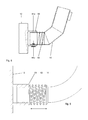
Figur 7 zeigt eine schematisch vereinfachte Darstellung einer Ausführungsform einesSensors 44im Ansaugstutzen 18 des Saugvorsatzes 12 (Figur 1 ) im Querschnitt.Der Sensor 44 ist hier zur Sensierung einer Verformung des Ansaugstutzens 18 aufgrund einer Schubkraft, welche durch den Benutzer eingebracht wird, vorgesehen und ausgebildet. Bei dem inFigur 6 und Figur 7 gezeigten Sensor 44 handelt es sich z. B. um einen Dehnungsmessstreifen, ein Piezoelement oder dergleichen. -
Figur 8 zeigt eine schematisch vereinfachte Darstellung einer alternativen Ausführungsform einesSensors 44b am Ansaugstutzen 18 im Querschnitt.Der Ansaugstutzen 18 istmit dem Saugvorsatz 12 mittels eines Lagers 58 gekoppelt und derSensor Lagers 58 angeordnet. Aufgrund einer federnden Verbindung 60 ist eine Reativbewegung (Drehen oder Teleskopieren)von Ansaugstutzen 18 und Saugvorsatz 12 möglich, welche mittels desSensors 44a, b sensierbar ist.Als Sensoren 44a, b kann beispielsweise eine Spulen-Magnet-Anordnung verwendet werden, anstelle eines Magneten kann auch ferromagnetisches Material eingesetzt werden. Ein Verschieben des Magnets (Sensor 44a) wird durch Änderung der Induktivität oder Resonanzfrequenz angezeigt. -
Figur 9 zeigt eine schematisch vereinfachte Darstellung einer Ausführungsform eines geeigneten Ansaugstutzens 18 im Querschnitt, welcher in seinen Grundzügen dem inFigur 8 Gezeigten entspricht. Hierumfasst das Lager 58 jedochein geschlitztes Federelement 62 zurVerbindung von Saugstutzen 18 undSaugvorsatz 12, welches eine teleskopierende Bewegung ermöglicht.
- FIG. 1
- a vacuum cleaner with an embodiment of a suction attachment according to the invention in side view,
- FIG. 2
- an embodiment of a suction attachment according to the invention in cross section,
- FIG. 3
- an alternative embodiment of a Saugvorsatzes invention in cross section,
- FIG. 4
- a sensor in a vacuum cleaner handle in cross-section,
- FIG. 5
- an embodiment of the sensor
FIG. 4 shown in a plan view, - FIG. 6
- a further embodiment of a sensor in a vacuum cleaner handle in cross-section,
- FIG. 7
- a sensor in an intake manifold in cross-section,
- FIG. 8
- an alternative embodiment of a sensor on an intake manifold in cross section,
- FIG. 9
- an embodiment of a suitable intake in cross section,
- FIG. 10
- an embodiment of a suitable mounting part for a sensor in cross section and
- FIG. 11
- a block diagram illustrating the effect context in the inventive control of the suction attachment.
-
FIG. 1 shows a schematically simplified illustration of avacuum cleaner 10 with an embodiment of asuction attachment 12 according to the invention in a side view. Thesuction attachment 12 comprises abristle roller 14 and arotatable drive 16 and is coupled by means of asuction nozzle 18 with a vacuumcleaner tube 20 of thevacuum cleaner 10. The vacuumcleaner tube 20 comprises at an upper end 22 ahandle 24. The vacuumcleaner hose 26 is in turn connected to abase unit 28. The combination ofintake manifold 18, vacuumcleaner tube 20, handle 24 and vacuumcleaner hose 26 creates an air path, not shown, from thesuction attachment 12 to thebase unit 28. -
FIG. 2 shows a schematically simplified representation of an embodiment of asuction attachment 12 according to the invention in cross-section, which substantially the inFIG. 1 Shown corresponds. Thebristle roller 14 is drivable by means of a bristle roller drive. This comprises afirst motor 32 and afirst belt drive 34 for thebristle roller 14. As for the movement of thesuction attachment 12 effective part of thetraction drive 16, a profiled wheel is shown. This can be driven via asecond belt drive 38 and asecond motor 40. In operation of thesuction attachment 12 contact both thebristle roller 14 and thetraction drive 16, namely its effective for moving thesuction attachment 12 part, ie z. B. the wheel shown, a substrate, not shown. -
FIG. 3 shows a schematically simplified representation of an alternative embodiment of a suction attachment according to the invention in cross section. In its basic features, thesuction attachment 12 corresponds to the inFIG. 2 Shown here, however, the illustratedmotor 40 is provided for driving both bristleroller 14 and drive 16 and formed. Themotor 40 is coupled by means of thefirst belt drive 34 with thebristle roller 14 and by means of thesecond belt drive 38 to thetraction drive 16. -
FIG. 4 shows a schematically simplified representation of an embodiment of asensor 44 in a vacuum cleaner handle 24 in cross section. Thehandle 24 includes at a first end 46 asuction tube 48 for a vacuum cleaner tube 20 (FIG.FIG. 1 ) and at asecond end 50 with a vacuum cleaner hose 26 (FIG.FIG. 1 ) connectable. OneAir path 52 in thehandle 24 allows air to pass from the vacuum cleaner tube 20 (FIG.FIG. 1 ) into the vacuum cleaner hose 26 (FIG.FIG. 1 ). Thehandle 24 includes on a top 54 as a sensor for a user applied thrust aswitch 56 for reversing the direction of travel of thedrive 16. Theswitch 56 as a sensor is amanual sensor 44, because this requires an operation by the user. Shown is also a sensor arranged in thehandle 24, with which a deformation of thehandle 24 due to a thrust, which is introduced by the user, is automatically sensed. The use of a manually operated sensor, so z. As aswitch 56, and anautomatic sensor 44 is alternative
or cumulatively possible. -
FIG. 5 shows a schematically simplified representation of an embodiment of theswitch 56 as inFIG. 4 shown from above. -
FIG. 6 shows a schematically simplified representation of another embodiment of asensor 44 in a vacuum cleaner handle 24 in cross section. Thehandle 24 corresponds to its basic features in theFIG. 4 Shown, however, is no switch 56 (FIG. 4 ) available. In addition, thesensor 44 is arranged in theintake manifold 48 and for sensing a deformation in the region of the coupling point between thehandle 24 and vacuum cleaner tube 20 (FIGS.FIG. 1 ) provided and trained. -
FIG. 7 shows a schematically simplified representation of an embodiment of asensor 44 in theintake manifold 18 of the suction attachment 12 (FIG.FIG. 1 ) in cross section. Thesensor 44 is here provided and configured to sense a deformation of theintake manifold 18 due to a thrust force introduced by the user. At the inFIG. 6 and FIG. 7 shownsensor 44 is z. B. to a strain gauge, a piezoelectric element or the like. -
FIG. 8 shows a schematically simplified illustration of an alternative embodiment of asensor intake manifold 18 in cross section. Theintake manifold 18 is coupled to thesuction attachment 12 by means of abearing 58, and thesensor bearing 58. Due to aresilient connection 60 is a Reativbewegung (turning or telescoping) ofintake manifold 18 andsuction attachment 12 is possible, which is sensed by means of thesensor 44a, b. As asensor 44a, b, for example, a coil-magnet arrangement can be used, instead of a magnet and ferromagnetic material can be used. A displacement of the magnet (sensor 44a) is indicated by changing the inductance or resonance frequency. -
FIG. 9 shows a schematically simplified representation of an embodiment of asuitable intake manifold 18 in cross-section, which in its basic features that inFIG. 8 Shown corresponds. Here, however, thebearing 58 comprises a slottedspring member 62 for connection ofsuction port 18 andsuction attachment 12, which allows a telescoping movement.
Anstelle der in
Damit lässt sich die Erfindung kurz wie folgt darstellen: Angegeben wird ein Saugvorsatz 12 für einen Staubsauger 10, wobei der Saugvorsatz 12 zumindest eine drehbare Borstenwalze 14 umfasst und wobei der Saugvorsatz 12 mit einem drehbaren Fahrantrieb 16 auf Basis einer sensierten Schubkraft bewegbar ist, ein Staubsauger 10 mit einem solchen Saugvorsatz 12 und mit zumindest einer Verarbeitungseinheit 70 zur Ansteuerung des Motors 40 sowie ein Verfahren zum Antrieb eines solchen Saugvorsatzes 12.Thus, the invention can be briefly illustrated as follows: Specified is a
Claims (9)
wobei der Saugvorsatz (12) zumindest eine drehbare Borstenwalze (14) umfasst, dadurch gekennzeichnet, dass
der Saugvorsatz (12) mittels eines elektromotorischen Antriebs mit zumindest einem drehbaren Fahrantrieb (16) und einem Motor (40) auf Basis einer sensierten Schubkraft bewegbar ist.Suction attachment (12) for a vacuum cleaner (10),
wherein the suction attachment (12) comprises at least one rotatable bristle roller (14), characterized in that
the suction attachment (12) can be moved by means of an electromotive drive with at least one rotatable travel drive (16) and a motor (40) on the basis of a sensed thrust force.
wobei der Sensor (44) zumindest ein Schalter (56), Dehnungsmessstreifen, Piezoelement, druckempfindlicher Widerstand, kapazitiver oder induktiver Sensor, Hallsensor oder magnetoresistiver Sensor ist.Suction attachment according to claim 2,
wherein the sensor (44) is at least one switch (56), strain gauges, piezoelectric element, pressure-sensitive resistor, capacitive or inductive sensor, Hall sensor or magnetoresistive sensor.
wobei der Motor (40) und der Fahrantrieb (16) direkt koppelbar sind und wobei der Saugvorsatz (12) eine Schaltung zur Drehrichtungsumschaltung des Motors (40) umfasst.Suction attachment according to one of the preceding claims,
wherein the motor (40) and the traction drive (16) are directly coupled and wherein the suction attachment (12) comprises a circuit for reversing the direction of rotation of the motor (40).
wobei der Motor (40) zum Antrieb von Borstenwalze (14) und Fahrantrieb (16) vorgesehen ist.Suction attachment according to one of the preceding claims,
wherein the motor (40) for driving the bristle roller (14) and drive (16) is provided.
und die Differenz mittels Änderung von Antriebsparametern, insbesondere Drehrichtung und/oder Drehgeschwindigkeit, des elektromotorischen Antriebs an einen vorgegeben oder vorgebbaren Wert angepasst wird.A method for driving a suction attachment according to any one of claims 1 to 7, wherein a difference of a sensed thrust force and a Saugvorsatz-pushing force of the electric motor driven Saugvorsatzes (12) determined
and the difference by changing drive parameters, in particular the direction of rotation and / or rotational speed, the electric motor drive is adapted to a predetermined or predetermined value.
Applications Claiming Priority (1)
| Application Number | Priority Date | Filing Date | Title |
|---|---|---|---|
| DE200910017120 DE102009017120A1 (en) | 2009-04-15 | 2009-04-15 | Suction attachment, vacuum cleaner and method of driving |
Publications (2)
| Publication Number | Publication Date |
|---|---|
| EP2241237A2 true EP2241237A2 (en) | 2010-10-20 |
| EP2241237A3 EP2241237A3 (en) | 2012-06-20 |
Family
ID=42289032
Family Applications (1)
| Application Number | Title | Priority Date | Filing Date |
|---|---|---|---|
| EP10401041A Withdrawn EP2241237A3 (en) | 2009-04-15 | 2010-04-01 | Suction header, vacuum cleaner and method for driving same |
Country Status (2)
| Country | Link |
|---|---|
| EP (1) | EP2241237A3 (en) |
| DE (1) | DE102009017120A1 (en) |
Families Citing this family (2)
| Publication number | Priority date | Publication date | Assignee | Title |
|---|---|---|---|---|
| DE102016010775A1 (en) | 2016-09-08 | 2018-03-08 | Sven Templin | Positioning assisted hand-held device |
| DE202016005473U1 (en) | 2016-09-08 | 2017-12-11 | Sven Templin | Positioning assisted hand-held device |
Family Cites Families (7)
| Publication number | Priority date | Publication date | Assignee | Title |
|---|---|---|---|---|
| US4347643A (en) * | 1981-01-23 | 1982-09-07 | The Singer Company | Power assist drive upright vacuum cleaner and power assist drive system therefor |
| JPH0815470B2 (en) | 1988-07-22 | 1996-02-21 | 松下電器産業株式会社 | Electric vacuum cleaner |
| EP0930840B1 (en) * | 1997-08-11 | 2005-12-14 | Koninklijke Philips Electronics N.V. | Vacuum cleaner provided with a suction nozzle with controllable electrical drive means |
| JP2002058623A (en) * | 2000-08-16 | 2002-02-26 | Masaya Hara | Vacuum cleaner |
| KR100531224B1 (en) | 2003-06-09 | 2005-11-28 | 삼성광주전자 주식회사 | Turbine brush |
| US7725223B2 (en) * | 2003-09-30 | 2010-05-25 | Techtronic Floor Care Technology Limited | Control arrangement for a propulsion unit for a self-propelled floor care appliance |
| KR100635823B1 (en) * | 2005-04-01 | 2006-10-19 | 엘지전자 주식회사 | Travel control grip for upright vacuum cleaners |
-
2009
- 2009-04-15 DE DE200910017120 patent/DE102009017120A1/en not_active Withdrawn
-
2010
- 2010-04-01 EP EP10401041A patent/EP2241237A3/en not_active Withdrawn
Also Published As
| Publication number | Publication date |
|---|---|
| EP2241237A3 (en) | 2012-06-20 |
| DE102009017120A1 (en) | 2010-10-28 |
Similar Documents
| Publication | Publication Date | Title |
|---|---|---|
| DE19653161C2 (en) | Remote controllable, automatically movable vacuum cleaner | |
| DE69821659T2 (en) | cleaning robot | |
| DE60111306T2 (en) | Bürstenkopfpositioniervorrichtung | |
| EP3569124B1 (en) | Cleaning device | |
| EP2245974B1 (en) | Method for operating a header device for a vacuum cleaner and corresponding header device | |
| DE102005046639A1 (en) | Automatically displaceable floor dust collector, has passive wheel is monitored for its movement and measure is initiated when intensity of movement of passive wheel changes | |
| DE102004014252A1 (en) | Vacuum cleaner operating method, involves measuring force acting as load and occurring during pull/push operation, where force is felt by user as resistance to operation, and automatically applying counterforce against resistance | |
| DE102008061251A1 (en) | Electric vacuum cleaner for cleaning dusts in e.g. surface of mattress, has electronic circuit for automatically adjusting suction capacity of suction blower based on type of nozzle of vacuum cleaner | |
| DE29913775U1 (en) | Floor care device, in particular vacuum cleaner | |
| EP2615959B1 (en) | Drive system for a cleaning device and cleaning device | |
| EP2241237A2 (en) | Suction header, vacuum cleaner and method for driving same | |
| DE10309621A1 (en) | Motor-powered, hand-guided transport vehicle, especially electric wheelchair, with intuitive grip control has sensors that detect forces/torques, pass measurement data to evaluation and control device | |
| WO2000079058A1 (en) | Sweeping unit | |
| DE102011013913B3 (en) | Electrical connector combination for charging electric vehicle, actuates manual insertion and manual release of plug into and from receptacle, such that plug which drives motor is inserted into receptacle | |
| DE102015102333B4 (en) | Sweeper and method for adjusting a sweeping roller of a sweeper | |
| EP3417756B1 (en) | Floor cleaning machine with brush pressure adjustment | |
| DE102015114082A1 (en) | Vacuum robot with rotating roller brush and method for cleaning a roller brush of a vacuum robot | |
| EP4275567B1 (en) | Floor cleaning machine and method for operating a floor cleaning machine | |
| EP1072727A2 (en) | Vehicle and method for cleaning surfaces | |
| EP3973837B1 (en) | Vacuum cleaner with head | |
| EP4098166B1 (en) | Floor nozzle for vacuum cleaner, vacuum cleaner, brush roller set, and method of operating a vacuum cleaner | |
| DE102021207321B4 (en) | Drive unit for a floor robot | |
| DE102009001513A1 (en) | Vehicle for supporting application of force of user, comprises wheel which is driven by electric drive system and operating unit for detecting user parameter for speed and drive direction of vehicle | |
| DE102019210971B4 (en) | Mobile cleaning robot | |
| DE102017123572B4 (en) | Hand-held transport aid device |
Legal Events
| Date | Code | Title | Description |
|---|---|---|---|
| PUAI | Public reference made under article 153(3) epc to a published international application that has entered the european phase |
Free format text: ORIGINAL CODE: 0009012 |
|
| AK | Designated contracting states |
Kind code of ref document: A2 Designated state(s): AT BE BG CH CY CZ DE DK EE ES FI FR GB GR HR HU IE IS IT LI LT LU LV MC MK MT NL NO PL PT RO SE SI SK SM TR |
|
| AX | Request for extension of the european patent |
Extension state: AL BA ME RS |
|
| PUAL | Search report despatched |
Free format text: ORIGINAL CODE: 0009013 |
|
| AK | Designated contracting states |
Kind code of ref document: A3 Designated state(s): AT BE BG CH CY CZ DE DK EE ES FI FR GB GR HR HU IE IS IT LI LT LU LV MC MK MT NL NO PL PT RO SE SI SK SM TR |
|
| AX | Request for extension of the european patent |
Extension state: AL BA ME RS |
|
| RIC1 | Information provided on ipc code assigned before grant |
Ipc: A47L 9/04 20060101AFI20120515BHEP Ipc: A47L 9/28 20060101ALI20120515BHEP |
|
| STAA | Information on the status of an ep patent application or granted ep patent |
Free format text: STATUS: THE APPLICATION IS DEEMED TO BE WITHDRAWN |
|
| 18D | Application deemed to be withdrawn |
Effective date: 20121221 |