EP2240119B1 - Stent and method of making a stent - Google Patents
Stent and method of making a stent Download PDFInfo
- Publication number
- EP2240119B1 EP2240119B1 EP08867792.7A EP08867792A EP2240119B1 EP 2240119 B1 EP2240119 B1 EP 2240119B1 EP 08867792 A EP08867792 A EP 08867792A EP 2240119 B1 EP2240119 B1 EP 2240119B1
- Authority
- EP
- European Patent Office
- Prior art keywords
- eyelet
- stent
- radius
- curvature
- edge
- Prior art date
- Legal status (The legal status is an assumption and is not a legal conclusion. Google has not performed a legal analysis and makes no representation as to the accuracy of the status listed.)
- Active
Links
- 238000004519 manufacturing process Methods 0.000 title claims description 9
- 239000000463 material Substances 0.000 claims description 51
- 238000000034 method Methods 0.000 claims description 17
- 238000005498 polishing Methods 0.000 claims description 10
- 238000003698 laser cutting Methods 0.000 claims description 6
- 238000001878 scanning electron micrograph Methods 0.000 description 7
- 229910001000 nickel titanium Inorganic materials 0.000 description 6
- 229920000728 polyester Polymers 0.000 description 5
- -1 polypropylene Polymers 0.000 description 5
- 239000000243 solution Substances 0.000 description 5
- PXHVJJICTQNCMI-UHFFFAOYSA-N Nickel Chemical compound [Ni] PXHVJJICTQNCMI-UHFFFAOYSA-N 0.000 description 4
- KDLHZDBZIXYQEI-UHFFFAOYSA-N Palladium Chemical compound [Pd] KDLHZDBZIXYQEI-UHFFFAOYSA-N 0.000 description 4
- 239000000560 biocompatible material Substances 0.000 description 4
- 229910052751 metal Inorganic materials 0.000 description 4
- 239000002184 metal Substances 0.000 description 4
- HLXZNVUGXRDIFK-UHFFFAOYSA-N nickel titanium Chemical compound [Ti].[Ti].[Ti].[Ti].[Ti].[Ti].[Ti].[Ti].[Ti].[Ti].[Ti].[Ni].[Ni].[Ni].[Ni].[Ni].[Ni].[Ni].[Ni].[Ni].[Ni].[Ni].[Ni].[Ni].[Ni] HLXZNVUGXRDIFK-UHFFFAOYSA-N 0.000 description 4
- BASFCYQUMIYNBI-UHFFFAOYSA-N platinum Chemical compound [Pt] BASFCYQUMIYNBI-UHFFFAOYSA-N 0.000 description 4
- 239000005020 polyethylene terephthalate Substances 0.000 description 4
- 229910001220 stainless steel Inorganic materials 0.000 description 4
- 239000010935 stainless steel Substances 0.000 description 4
- 206010002329 Aneurysm Diseases 0.000 description 3
- 241001465754 Metazoa Species 0.000 description 3
- 230000007423 decrease Effects 0.000 description 3
- 229920000139 polyethylene terephthalate Polymers 0.000 description 3
- 229920000642 polymer Polymers 0.000 description 3
- 229920001343 polytetrafluoroethylene Polymers 0.000 description 3
- 239000004810 polytetrafluoroethylene Substances 0.000 description 3
- 239000003356 suture material Substances 0.000 description 3
- VYZAMTAEIAYCRO-UHFFFAOYSA-N Chromium Chemical compound [Cr] VYZAMTAEIAYCRO-UHFFFAOYSA-N 0.000 description 2
- 229920004934 Dacron® Polymers 0.000 description 2
- NBIIXXVUZAFLBC-UHFFFAOYSA-N Phosphoric acid Chemical compound OP(O)(O)=O NBIIXXVUZAFLBC-UHFFFAOYSA-N 0.000 description 2
- 239000004743 Polypropylene Substances 0.000 description 2
- BQCADISMDOOEFD-UHFFFAOYSA-N Silver Chemical compound [Ag] BQCADISMDOOEFD-UHFFFAOYSA-N 0.000 description 2
- QAOWNCQODCNURD-UHFFFAOYSA-N Sulfuric acid Chemical compound OS(O)(=O)=O QAOWNCQODCNURD-UHFFFAOYSA-N 0.000 description 2
- RTAQQCXQSZGOHL-UHFFFAOYSA-N Titanium Chemical compound [Ti] RTAQQCXQSZGOHL-UHFFFAOYSA-N 0.000 description 2
- HZEWFHLRYVTOIW-UHFFFAOYSA-N [Ti].[Ni] Chemical compound [Ti].[Ni] HZEWFHLRYVTOIW-UHFFFAOYSA-N 0.000 description 2
- 229910045601 alloy Inorganic materials 0.000 description 2
- 239000000956 alloy Substances 0.000 description 2
- 238000013459 approach Methods 0.000 description 2
- 238000000429 assembly Methods 0.000 description 2
- 230000000712 assembly Effects 0.000 description 2
- 210000004204 blood vessel Anatomy 0.000 description 2
- 229910052804 chromium Inorganic materials 0.000 description 2
- 239000011651 chromium Substances 0.000 description 2
- 229910017052 cobalt Inorganic materials 0.000 description 2
- 239000010941 cobalt Substances 0.000 description 2
- GUTLYIVDDKVIGB-UHFFFAOYSA-N cobalt atom Chemical compound [Co] GUTLYIVDDKVIGB-UHFFFAOYSA-N 0.000 description 2
- 239000002131 composite material Substances 0.000 description 2
- 230000006835 compression Effects 0.000 description 2
- 238000007906 compression Methods 0.000 description 2
- 230000003247 decreasing effect Effects 0.000 description 2
- 239000008151 electrolyte solution Substances 0.000 description 2
- PCHJSUWPFVWCPO-UHFFFAOYSA-N gold Chemical compound [Au] PCHJSUWPFVWCPO-UHFFFAOYSA-N 0.000 description 2
- 229910052737 gold Inorganic materials 0.000 description 2
- 239000010931 gold Substances 0.000 description 2
- 238000002513 implantation Methods 0.000 description 2
- 229910001026 inconel Inorganic materials 0.000 description 2
- 229910052741 iridium Inorganic materials 0.000 description 2
- GKOZUEZYRPOHIO-UHFFFAOYSA-N iridium atom Chemical compound [Ir] GKOZUEZYRPOHIO-UHFFFAOYSA-N 0.000 description 2
- 239000007769 metal material Substances 0.000 description 2
- 150000002739 metals Chemical class 0.000 description 2
- 229910052759 nickel Inorganic materials 0.000 description 2
- 229910052763 palladium Inorganic materials 0.000 description 2
- 229910052697 platinum Inorganic materials 0.000 description 2
- 229920001155 polypropylene Polymers 0.000 description 2
- 229910052709 silver Inorganic materials 0.000 description 2
- 239000004332 silver Substances 0.000 description 2
- 238000011477 surgical intervention Methods 0.000 description 2
- 229910052715 tantalum Inorganic materials 0.000 description 2
- GUVRBAGPIYLISA-UHFFFAOYSA-N tantalum atom Chemical compound [Ta] GUVRBAGPIYLISA-UHFFFAOYSA-N 0.000 description 2
- 239000004753 textile Substances 0.000 description 2
- 229910052719 titanium Inorganic materials 0.000 description 2
- 239000010936 titanium Substances 0.000 description 2
- WFKWXMTUELFFGS-UHFFFAOYSA-N tungsten Chemical compound [W] WFKWXMTUELFFGS-UHFFFAOYSA-N 0.000 description 2
- 229910052721 tungsten Inorganic materials 0.000 description 2
- 239000010937 tungsten Substances 0.000 description 2
- 241000282412 Homo Species 0.000 description 1
- UFHFLCQGNIYNRP-UHFFFAOYSA-N Hydrogen Chemical compound [H][H] UFHFLCQGNIYNRP-UHFFFAOYSA-N 0.000 description 1
- 241000124008 Mammalia Species 0.000 description 1
- GRYLNZFGIOXLOG-UHFFFAOYSA-N Nitric acid Chemical compound O[N+]([O-])=O GRYLNZFGIOXLOG-UHFFFAOYSA-N 0.000 description 1
- 206010057469 Vascular stenosis Diseases 0.000 description 1
- 230000003187 abdominal effect Effects 0.000 description 1
- 239000002253 acid Substances 0.000 description 1
- 238000004873 anchoring Methods 0.000 description 1
- 210000001367 artery Anatomy 0.000 description 1
- 239000012620 biological material Substances 0.000 description 1
- 239000008280 blood Substances 0.000 description 1
- 210000004369 blood Anatomy 0.000 description 1
- 230000017531 blood circulation Effects 0.000 description 1
- 238000004140 cleaning Methods 0.000 description 1
- 239000004020 conductor Substances 0.000 description 1
- 239000000356 contaminant Substances 0.000 description 1
- 230000007797 corrosion Effects 0.000 description 1
- 238000005260 corrosion Methods 0.000 description 1
- 230000008878 coupling Effects 0.000 description 1
- 238000010168 coupling process Methods 0.000 description 1
- 238000005859 coupling reaction Methods 0.000 description 1
- 230000007547 defect Effects 0.000 description 1
- 230000032798 delamination Effects 0.000 description 1
- 230000008021 deposition Effects 0.000 description 1
- 229910003460 diamond Inorganic materials 0.000 description 1
- 239000010432 diamond Substances 0.000 description 1
- 201000010099 disease Diseases 0.000 description 1
- 208000037265 diseases, disorders, signs and symptoms Diseases 0.000 description 1
- 230000000694 effects Effects 0.000 description 1
- 239000004744 fabric Substances 0.000 description 1
- 239000000835 fiber Substances 0.000 description 1
- 239000012530 fluid Substances 0.000 description 1
- 229920002313 fluoropolymer Polymers 0.000 description 1
- 230000002496 gastric effect Effects 0.000 description 1
- 239000003292 glue Substances 0.000 description 1
- 238000009499 grossing Methods 0.000 description 1
- 229910052739 hydrogen Inorganic materials 0.000 description 1
- 239000001257 hydrogen Substances 0.000 description 1
- 230000000642 iatrogenic effect Effects 0.000 description 1
- 238000007654 immersion Methods 0.000 description 1
- 238000010348 incorporation Methods 0.000 description 1
- 238000003780 insertion Methods 0.000 description 1
- 230000037431 insertion Effects 0.000 description 1
- 238000009940 knitting Methods 0.000 description 1
- 239000007788 liquid Substances 0.000 description 1
- 239000000203 mixture Substances 0.000 description 1
- 229910017604 nitric acid Inorganic materials 0.000 description 1
- 239000012811 non-conductive material Substances 0.000 description 1
- 239000003921 oil Substances 0.000 description 1
- 239000002861 polymer material Substances 0.000 description 1
- 229920002635 polyurethane Polymers 0.000 description 1
- 239000004814 polyurethane Substances 0.000 description 1
- 230000002028 premature Effects 0.000 description 1
- 238000002360 preparation method Methods 0.000 description 1
- 210000002254 renal artery Anatomy 0.000 description 1
- 230000000241 respiratory effect Effects 0.000 description 1
- 238000007789 sealing Methods 0.000 description 1
- 239000000126 substance Substances 0.000 description 1
- 230000002792 vascular Effects 0.000 description 1
- XLYOFNOQVPJJNP-UHFFFAOYSA-N water Substances O XLYOFNOQVPJJNP-UHFFFAOYSA-N 0.000 description 1
- 238000009941 weaving Methods 0.000 description 1
Images


Classifications
-
- A—HUMAN NECESSITIES
- A61—MEDICAL OR VETERINARY SCIENCE; HYGIENE
- A61F—FILTERS IMPLANTABLE INTO BLOOD VESSELS; PROSTHESES; DEVICES PROVIDING PATENCY TO, OR PREVENTING COLLAPSING OF, TUBULAR STRUCTURES OF THE BODY, e.g. STENTS; ORTHOPAEDIC, NURSING OR CONTRACEPTIVE DEVICES; FOMENTATION; TREATMENT OR PROTECTION OF EYES OR EARS; BANDAGES, DRESSINGS OR ABSORBENT PADS; FIRST-AID KITS
- A61F2/00—Filters implantable into blood vessels; Prostheses, i.e. artificial substitutes or replacements for parts of the body; Appliances for connecting them with the body; Devices providing patency to, or preventing collapsing of, tubular structures of the body, e.g. stents
- A61F2/02—Prostheses implantable into the body
- A61F2/04—Hollow or tubular parts of organs, e.g. bladders, tracheae, bronchi or bile ducts
- A61F2/06—Blood vessels
- A61F2/07—Stent-grafts
-
- A—HUMAN NECESSITIES
- A61—MEDICAL OR VETERINARY SCIENCE; HYGIENE
- A61F—FILTERS IMPLANTABLE INTO BLOOD VESSELS; PROSTHESES; DEVICES PROVIDING PATENCY TO, OR PREVENTING COLLAPSING OF, TUBULAR STRUCTURES OF THE BODY, e.g. STENTS; ORTHOPAEDIC, NURSING OR CONTRACEPTIVE DEVICES; FOMENTATION; TREATMENT OR PROTECTION OF EYES OR EARS; BANDAGES, DRESSINGS OR ABSORBENT PADS; FIRST-AID KITS
- A61F2/00—Filters implantable into blood vessels; Prostheses, i.e. artificial substitutes or replacements for parts of the body; Appliances for connecting them with the body; Devices providing patency to, or preventing collapsing of, tubular structures of the body, e.g. stents
- A61F2/82—Devices providing patency to, or preventing collapsing of, tubular structures of the body, e.g. stents
- A61F2/86—Stents in a form characterised by the wire-like elements; Stents in the form characterised by a net-like or mesh-like structure
- A61F2/89—Stents in a form characterised by the wire-like elements; Stents in the form characterised by a net-like or mesh-like structure the wire-like elements comprising two or more adjacent rings flexibly connected by separate members
-
- A—HUMAN NECESSITIES
- A61—MEDICAL OR VETERINARY SCIENCE; HYGIENE
- A61F—FILTERS IMPLANTABLE INTO BLOOD VESSELS; PROSTHESES; DEVICES PROVIDING PATENCY TO, OR PREVENTING COLLAPSING OF, TUBULAR STRUCTURES OF THE BODY, e.g. STENTS; ORTHOPAEDIC, NURSING OR CONTRACEPTIVE DEVICES; FOMENTATION; TREATMENT OR PROTECTION OF EYES OR EARS; BANDAGES, DRESSINGS OR ABSORBENT PADS; FIRST-AID KITS
- A61F2/00—Filters implantable into blood vessels; Prostheses, i.e. artificial substitutes or replacements for parts of the body; Appliances for connecting them with the body; Devices providing patency to, or preventing collapsing of, tubular structures of the body, e.g. stents
- A61F2/82—Devices providing patency to, or preventing collapsing of, tubular structures of the body, e.g. stents
- A61F2/86—Stents in a form characterised by the wire-like elements; Stents in the form characterised by a net-like or mesh-like structure
- A61F2/90—Stents in a form characterised by the wire-like elements; Stents in the form characterised by a net-like or mesh-like structure characterised by a net-like or mesh-like structure
- A61F2/91—Stents in a form characterised by the wire-like elements; Stents in the form characterised by a net-like or mesh-like structure characterised by a net-like or mesh-like structure made from perforated sheets or tubes, e.g. perforated by laser cuts or etched holes
-
- A—HUMAN NECESSITIES
- A61—MEDICAL OR VETERINARY SCIENCE; HYGIENE
- A61F—FILTERS IMPLANTABLE INTO BLOOD VESSELS; PROSTHESES; DEVICES PROVIDING PATENCY TO, OR PREVENTING COLLAPSING OF, TUBULAR STRUCTURES OF THE BODY, e.g. STENTS; ORTHOPAEDIC, NURSING OR CONTRACEPTIVE DEVICES; FOMENTATION; TREATMENT OR PROTECTION OF EYES OR EARS; BANDAGES, DRESSINGS OR ABSORBENT PADS; FIRST-AID KITS
- A61F2/00—Filters implantable into blood vessels; Prostheses, i.e. artificial substitutes or replacements for parts of the body; Appliances for connecting them with the body; Devices providing patency to, or preventing collapsing of, tubular structures of the body, e.g. stents
- A61F2/02—Prostheses implantable into the body
- A61F2/04—Hollow or tubular parts of organs, e.g. bladders, tracheae, bronchi or bile ducts
- A61F2/06—Blood vessels
- A61F2/07—Stent-grafts
- A61F2002/072—Encapsulated stents, e.g. wire or whole stent embedded in lining
-
- A—HUMAN NECESSITIES
- A61—MEDICAL OR VETERINARY SCIENCE; HYGIENE
- A61F—FILTERS IMPLANTABLE INTO BLOOD VESSELS; PROSTHESES; DEVICES PROVIDING PATENCY TO, OR PREVENTING COLLAPSING OF, TUBULAR STRUCTURES OF THE BODY, e.g. STENTS; ORTHOPAEDIC, NURSING OR CONTRACEPTIVE DEVICES; FOMENTATION; TREATMENT OR PROTECTION OF EYES OR EARS; BANDAGES, DRESSINGS OR ABSORBENT PADS; FIRST-AID KITS
- A61F2/00—Filters implantable into blood vessels; Prostheses, i.e. artificial substitutes or replacements for parts of the body; Appliances for connecting them with the body; Devices providing patency to, or preventing collapsing of, tubular structures of the body, e.g. stents
- A61F2/02—Prostheses implantable into the body
- A61F2/04—Hollow or tubular parts of organs, e.g. bladders, tracheae, bronchi or bile ducts
- A61F2/06—Blood vessels
- A61F2/07—Stent-grafts
- A61F2002/075—Stent-grafts the stent being loosely attached to the graft material, e.g. by stitching
-
- A—HUMAN NECESSITIES
- A61—MEDICAL OR VETERINARY SCIENCE; HYGIENE
- A61F—FILTERS IMPLANTABLE INTO BLOOD VESSELS; PROSTHESES; DEVICES PROVIDING PATENCY TO, OR PREVENTING COLLAPSING OF, TUBULAR STRUCTURES OF THE BODY, e.g. STENTS; ORTHOPAEDIC, NURSING OR CONTRACEPTIVE DEVICES; FOMENTATION; TREATMENT OR PROTECTION OF EYES OR EARS; BANDAGES, DRESSINGS OR ABSORBENT PADS; FIRST-AID KITS
- A61F2/00—Filters implantable into blood vessels; Prostheses, i.e. artificial substitutes or replacements for parts of the body; Appliances for connecting them with the body; Devices providing patency to, or preventing collapsing of, tubular structures of the body, e.g. stents
- A61F2/02—Prostheses implantable into the body
- A61F2/30—Joints
- A61F2002/30001—Additional features of subject-matter classified in A61F2/28, A61F2/30 and subgroups thereof
- A61F2002/30108—Shapes
- A61F2002/3011—Cross-sections or two-dimensional shapes
-
- A—HUMAN NECESSITIES
- A61—MEDICAL OR VETERINARY SCIENCE; HYGIENE
- A61F—FILTERS IMPLANTABLE INTO BLOOD VESSELS; PROSTHESES; DEVICES PROVIDING PATENCY TO, OR PREVENTING COLLAPSING OF, TUBULAR STRUCTURES OF THE BODY, e.g. STENTS; ORTHOPAEDIC, NURSING OR CONTRACEPTIVE DEVICES; FOMENTATION; TREATMENT OR PROTECTION OF EYES OR EARS; BANDAGES, DRESSINGS OR ABSORBENT PADS; FIRST-AID KITS
- A61F2230/00—Geometry of prostheses classified in groups A61F2/00 - A61F2/26 or A61F2/82 or A61F9/00 or A61F11/00 or subgroups thereof
- A61F2230/0002—Two-dimensional shapes, e.g. cross-sections
-
- Y—GENERAL TAGGING OF NEW TECHNOLOGICAL DEVELOPMENTS; GENERAL TAGGING OF CROSS-SECTIONAL TECHNOLOGIES SPANNING OVER SEVERAL SECTIONS OF THE IPC; TECHNICAL SUBJECTS COVERED BY FORMER USPC CROSS-REFERENCE ART COLLECTIONS [XRACs] AND DIGESTS
- Y10—TECHNICAL SUBJECTS COVERED BY FORMER USPC
- Y10T—TECHNICAL SUBJECTS COVERED BY FORMER US CLASSIFICATION
- Y10T29/00—Metal working
- Y10T29/49—Method of mechanical manufacture
- Y10T29/49995—Shaping one-piece blank by removing material
- Y10T29/49996—Successive distinct removal operations
Definitions
- This invention relates to endoluminal medical devices for implantation within the human or animal body for treatment of endovascular disease.
- this invention relates to stents for accommodating suture material having a locally polished region.
- Stent grafts may be formed from a tube of a biocompatible material in combination with one or more stents to maintain a lumen therethrough.
- the stents are attached to the graft material in a number of ways, including by suturing the stent to the graft material.
- prostheses seal off the failed portion of the vessel.
- a prosthesis of this type can, for example, treat aneurysms of the abdominal aortic, iliac, or branch vessels such as the renal arteries.
- endoluminal devices are used by physicians. Many other applications for endoluminal devices are known and/or will be developed in the future.
- similar procedures may also be used to deploy vascular filters, occluders, artificial valves and other endoprosthetic devices.
- the stent In order to deliver a stent or stent-graft though narrow passageways, the stent is typically collapsed into a delivery configuration with a small diameter. The collapsed stent structure may then be inserted into a sheath which retains the stent in the delivery configuration until it is released. Because the stent must be significantly collapsed in this configuration, a large strain is introduced into the stent structure. Since a typical stent structure is only collapsed into the delivery configuration one time or a minimal number of times, it is generally considered that the stent structure can accommodate a large strain level in this application without resulting in permanent damage to the stent structure.
- the stent structure expands and contacts the lumen wall. In this process, a large portion of the strain is relieved.
- the stress of compression can cause damage to the stent-graft. Specifically, the stress of compression can cause the sutures to wear against the graft material.
- the problem of suture wear is increased in diamond-shaped stents.
- the diamond-shaped stents may have eyelets to accommodate the sutures for suturing the stent to the graft.
- these stents are so low profile, when they are compressed into the delivery device, they compress and leave no spaces. The edges of the eyelets thus wear on the suture and lead to unacceptable suture life span. They eventually fray and break.
- Stent-grafts may also be subject to the problem of graft wear.
- Stents are often constructed by laser-cutting a cannula. Laser-cutting the cannula produced substantially rectangular, or even trapezoidal, stent cross-sections which can wear against the graft material and also cause the sutures to weaken. Additionally, at the regions where the stent contacts the graft, the graft material may weaken and tear due to the pressure of blood flow through the prosthesis. This graft wear contributes to a reduced life of the prosthesis.
- Electropolishing methods may reduce the rough surfaces of the stent and decrease the blunt rectangular edges of the stent that often contribute to the problems of graft wear and suture wear.
- electropolishing tends to remove stent material in a relatively uniform manner. Therefore, electropolishing to remove material from the corners of the stent to create a more circular cross-section often results in stent material removed from the struts of the stent. The removal of material from the struts of the stent may result in a decreased integrity of the stent, reducing the overall life of the prosthesis.
- US 2002/0049490 describes an endoluminal prosthesis having a compressible and expansible single-piece thick walled cylindrical structure.
- the cylindrical structure is comprised of curved elongated beams which intermittently merge with adjacent curved elongated beams.
- Each beam has a radial thickness greater than the circumferential width.
- the configuration of the curved beams reduces stress concentrations in the expanded and compressed condition of the prosthesis.
- Features are provided for high expansion ratios allowing the prosthesis to collapse into a very small diameter and expand into a very large diameter.
- EP 0 539 237 describes a transluminal grafting system for grafting a prosthesis to the wall of a lumen.
- the system includes a tubular graft provided with spring assemblies and anchoring barbs.
- the prosthesis is mounted on an apertured tubular carrier and a central control means is inserted into the bore of the apertured carrier. Mooring loops are attached to the prosthesis, pass through the apertures of the tubular carrier, and engage the central control means.
- An introducer sheath covers the system for smooth insertion into a lumen. When the graft has been positioned, the central control means maintains the axial position of the prosthesis. When the introducer sheath is pulled, the prosthesis is exposed and the spring assemblies return to an expanded state and anchor the graft against the internal wall of the lumen.
- the present invention seeks to provide an improved endoluminal medical device, such as a stent and an improved method of manufacturing a medical device.
- the preferred embodiments provide an endoluminal device with an improved eyelet, where the eyelet region of the endoluminal device is locally polished. It has been found that the improved eyelet structure allows the graft material to be affixed to the stent without premature failure due to suture wear and/or graft wear.
- a stent for use in a stent graft as specified in claim 1.
- the preferred embodiment provides a variably polished stent, in particular a stent with an improved eyelet, where the eyelet region of the stent is locally polished.
- a method of manufacturing the stent with an improved eyelet also is disclosed. The effect of locally polishing the eyelet region to yield rounded eyelet edges results in less stress to the material of the sutures and decreases graft wear, which increases the life of the overall endoluminal device.
- the stent may include a strut region including at least two struts, the struts having at least one radius of curvature.
- a bend connects the two struts at an eyelet region.
- the strut region and the eyelet region are electropolished, and the eyelet region is locally polished.
- the eyelet positioned in the eyelet region has at least one radius of curvature that is greater than zero.
- the struts have an edge having a radius of curvature.
- the radius of curvature of the struts approaches that of a sharp corner, which has a radius of curvature of zero (0). Because a perfectly sharp corner is not likely to be achieved after electropolishing, the radius of curvature of the strut may be less than .001 mm.
- the eyelet region is locally polished, such that the edge of the eyelet becomes rounded.
- the radius of curvature of the eyelet will be approximately the same regardless of where along the edge of the eyelet the radius is measured.
- An acceptable range of the radius of curvature of the eyelet may be about 0.01 mm to a value where a cross-section of the eyelet is circular.
- the radius of curvature of the may be limited no less than 1/10 of the radius of the suture that attaches the strut to graft material.
- the lower range of the radius of curvature of the eyelet may be at least an order of magnitude higher than the radius of curvature of the strut.
- the radius of curvature of the strut may be about 001 mm and the radius of curvature of the locally polished eyelet may be at eyelet may be limited to be no less than 1/10 of the radius of the suture, to avoid the eyelet severing or fraying the suture.
- the lower range of the radius of curvature of the eyelet may be at least an order of magnitude higher than the radius of curvature of the strut.
- the radius of curvature of the strut may be about 0.001 mm and the radius of curvature of the locally polished eyelet may be at least about 0.01 mm.
- the radius of curvature of the eyelet may be no less than 1/10 of the radius of the suture and is at least an order of magnitude greater than the at least one radius of curvature of the strut.
- the stent may be formed from biocompatible material.
- the materials used in the manufacture of the device may be selected from a well-known list of suitable metals. Preferred materials include those materials that can provide the desired functional characteristics with respect to mechanical load bearing, biological compatibility, modulus of elasticity, or other desired properties.
- the stent includes a metallic material selected from stainless steel, nickel, silver, platinum, palladium, gold, titanium, tantalum, iridium, tungsten, cobalt, chromium, a nickel-titanium alloy, a superelastic nickel-titanium (NiTi) alloy sold under the trade name NITINOL® or inconel.
- the individual stent units are manufactured from Nitinol or stainless steel.
- Figure 6A is an SEM image of the locally polished stent 42 which displays the eyelet region 52 at 100X magnification.
- the eyelet region 52 appears to be smooth.
- Figure 6B is an SEM image that displays the same locally polished stent 42 at 250X magnification and visually confirms the impact of the localized polishing on the eyelet region 52.
- the eyelet edges 60 are rounded and sharp edges 38 of the eyelet 36 of the electropolished stent 24 seen in Figure 3B are eliminated.
- the locally polished stent 42 may be attached to graft material to form the endoluminal device 40 as shown in Figure 4 .
- Figure 7 shows attachment of the locally polished stent 42 to graft material 62.
- graft material 62 may be affixed to the stent 42 using sutures 64, 65 which are threaded through the eyelet 54 using a double suture technique.
- the eyelet may be an elliptical shape in order to accommodate the double suture attachment.
- Suture material may be polypropylene or any other suitable material known in the art. as an artery.
- Tubular prosthetic devices include single and both branched and bifurcated devices.
- endoluminal refers to or describes objects that can be placed inside a lumen or a body passageway in a human or animal body.
- a lumen or a body passageway can be an existing lumen or a lumen created by surgical intervention.
- the terms “lumen” or “body passageway” are intended to have a broad meaning and encompasses any duct (e.g., natural or iatrogenic) within the human body and can include a member selected from the group comprising: blood vessels, respiratory ducts, gastrointestinal ducts, and the like.
- Endoluminal device or “endoluminal prosthesis” thus describes devices that can be placed inside one of these lumens.
- stent means any device or structure that adds rigidity, expansion force or support to a prosthesis.
- a stent is used to obtain and maintain the patency of the body passageway while maintaining the integrity of the passageway. Also, the stent may be used to form a seal.
- the stent may be coated with a polymeric material, for example, by immersion in molten polymer or any other method known to one of skill in the art.
- a Z-stent is a stent that has alternating struts and peaks ( i.e ., bends) and defines a generally cylindrical lumen.
- the "amplitude" of a Z-stent is the distance between two bends connected by a single strut.
- the "period” of a Z-stent is the total number of bends in the Z-stent divided by two, or the total number of struts divided by two.
- the stent may represent a plurality of discontinuous devices. In another configuration, the stent may represent one device. The stent may be located on the exterior of the device, the interior of the device, or both. A stent may be self-expanding, balloon-expandable or may have characteristics of both. A variety of other stent configurations are also contemplated by the use of the term "stent".
- graft or "graft material” describes an object, device, or structure that is joined to or that is capable of being joined to a body part to enhance, repair, or replace a portion or a function of that body part.
- a graft by itself or with the addition of other elements, such as structural components, can be an endoluminal prosthesis.
- the graft comprises a single material, a blend of materials, a weave, a laminate, or a composite of two or more materials.
- the graft can also comprise polymer material that may be layered onto the mandrel of the described embodiments. Preferably, polymers, although added in layers onto the mandrel, after curing, result in one layer that encapsulates a stent or woven graft. This also aids in decreasing the incidence of delamination of the resulting endovascular prosthesis.
- a stent may be attached to a graft to form a "stent graft.”
- patient refers to any mammal, especially humans.
- the teachings herein provide an endoluminal device with an improved eyelet, where the eyelet region of the implantable device is locally polished.
- the teachings herein provide for an eyelet geometry which is non-circular, such as oval, elliptical, slot-shaped and the like. A method of manufacturing the endoluminal device with an improved eyelet also is described.
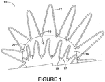
- the implantable device 10 is formed of an attachment z-stent 12 that is secured to main body 14 of the implantable device by threading a suture 16 through the loops 18 at the end of the attachment z-stent 12 and connecting the attachment z-stent 12 to the graft material 22.
- Proximal sealing stent 17 is attached to the graft material 22 via a suture 19.
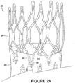
- FIG. 2A shows an implantable device 20 comprising a stent 24, specifically a cannula cut diamond-shaped stent, in which the entire stent 24 has been electropolished.
- This implantable device 20 provides significant radial force, but maintains a low profile in its loaded configuration.
- An example of such a diamond shaped stent device is described in US-A- 2007/0021824 entitled “Endoluminal Device With Improved Tapered Beams,” which is herein incorporated by reference.
- FIG. 2B depicts an enlarged view of the stent 24.
- the stent 24 includes a strut region 26, having at least two struts 28, 30 that are connected by a bend 32 at an eyelet region 34.
- the strut region 26 is the main "load carrying" portion of the stent which may be laser cut and electropolished.
- An eyelet 36 which may be substantially circular, is located at the eyelet region 34.
- the stent 24 is connected to graft material 25 via an eyelet 36 with a suture 27.
- any cannula cut stent is that edges are created due to the substantially rectangular or trapezoidal cross-section as a result of the laser cutting process. Even though these stents are electropolished to evenly remove material, a relatively sharp edge remains.
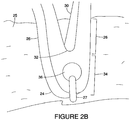
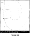
- Figure 3A an SEM image of the an electropolished cannula cut stent 24, displays an eyelet region 34 at 100X magnification. The eyelet region 34 appears to be smooth.
- Figure 3B is an SEM image that displays the same electropolished cannula cut stent 24 at 250X magnification.
- Figure 3B reveals that the edges 38, 39 of the eyelet 36 are sharp and that the cross-section of the eyelet 36 is substantially rectangular.
- FIG. 4 shows an endoluminal device 40 comprising a stent 42, specifically a cannula cut diamond-shaped stent.
- This endoluminal device 40 provides significant radial force, but maintains a low profile in its loaded configuration.
- the stent 42 is comprised of at strut region 44 having at least two struts 46, 48 that are connected by a bend 50 at an eyelet region 52.
- the strut region 44 is the main "load carrying" portion of the stent 42.
- the stent 42 is electropolished.
- An eyelet 54 is located at the eyelet region 52. In this stent 42, in contrast to the stent 24 discussed above, the eyelet region 52 has been locally polished to smooth out the sharp edges of the eyelet 54.
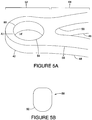
- an enlarged view of the stent 42 displays the properties of the locally polished eyelet region 52.
- the strut 48 has an edge 56 having a radius of curvature.
- the radius of curvature of the strut approaches that of a sharp corner, which has a radius of curvature of zero (0). Because a perfectly sharp corner is not likely to be achieved after electropolishing, the radius of curvature of the strut is typically less than 0.001 mm. This value is adequate to maintain a strut 48 cross-section sufficient to achieve adequate durability and radial force.
- FIG. 5B depicts the eyelet cross-section 58 taken along the line A-A'.
- the radius of curvature of the eyelet will be approximately the same regardless of where along the edge 60 of the eyelet 54 the radius is measured.
- an acceptable range of the radius of curvature of the eyelet is about 0.01 mm to a value where a cross-section of the eyelet 54 is circular.
- the radius of curvature of the eyelet may be 0.10 mm.
- the radius of curvature of the eyelet may be limited to be no less than 1/10 of the radius of the suture, to avoid the eyelet severing or fraying the suture.
- the lower range of the radius of curvature of the eyelet may be at least an order of magnitude higher than the radius of curvature of the strut.
- the radius of curvature of the strut may be about 0.001 mm and the radius of curvature of the locally polished eyelet may be at least about 0.01 mm.
- the radius one radius of curvature of the eyelet may be no less than 1/10 radius of suture and is at least an order of magnitude greater than the at least one radius of curvature of the strut.
- the stent may be formed from biocompatible material.
- the materials used in the manufacture of the device may be selected from a well-known list of suitable metals. Preferred materials include those materials that can provide the desired functional characteristics with respect to mechanical load bearing, biological compatibility, modulus of elasticity, or other desired properties.
- the stent includes a metallic material selected from stainless steel, nickel, silver, platinum, palladium, gold, titanium, tantalum, iridium, tungsten, cobalt, chromium, a nickel-titanium alloy, a superelastic nickel-titanium (NiTi) alloy sold under the trade name NITINOL® or inconel.
- the individual stent units are manufactured from Nitinol or stainless steel.
- Figure 6A is an SEM image of the locally polished stent 42 which displays the eyelet region 52 at 100X magnification.
- the eyelet region 52 appears to be smooth.
- Figure 6B is an SEM image that displays the same locally polished stent 42 at 250X magnification and visually confirms the impact of the localized polishing on the eyelet region 52.
- the eyelet edges 60 are rounded and sharp edges 38 of the eyelet 36 of the electropolished stent 24 seen in Figure 3B are eliminated.
- the locally polished stent 42 may be attached to graft material to form the endoluminal device 40 as shown in Figure 4 .
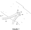
- Figure 7 shows attachment of the locally polished stent 42 to graft material 62.
- graft material 62 may be affixed to the stent 42 using sutures 64, 65 which are threaded through the eyelet 54 using a double suture technique.
- the eyelet may be an elliptical shape in order to accommodate the double suture attachment.
- Suture material may be polypropylene or any other suitable material known in the art.
- the tubular graft material may be constructed from a biocompatible textile fabric, a polymer, biomaterial, or a composite thereof.
- biocompatible materials from which textile graft material can be formed include polyesters, such as polyethylene terephthalate); fluorinated polymers, such as polytetrafluoroethylene (PTFE) and fibers of expanded PTFE; and polyurethanes.
- the graft material is a woven polyester. More preferably, the graft material is a polyethylene terephthalate (PET), such as DACRON® (DUPONT, Wilmington, DE) or TWILLWEAVE MICREL® (VASCUTEK, Renfrewshire, Scotland).
- Woven polyesters such as Dacron possess varying degrees of porosity, where the degree of porosity can be selectively controlled based on the weaving or knitting process that is used to produce the woven polyester. Consequently, depending on the application, the porosity can be adjusted to encourage incorporation of a patient's tissue into the woven graft material, which in turn may more securely anchor the prosthesis within the patient's vessel or lumen. Furthermore, the degree of porosity can also be adjusted to provide a woven graft material that is impermeable to liquids, including blood or other physiological fluids.
- the woven polyester of the graft material may comprise a plurality of yarns.
- a method of manufacturing the implantable device 40 also is provided.
- Standard laser cutting techniques which are known in the art may be employed to manufacture the stent 42 as described above.
- the stent structure may be fabricated by laser cutting the structural members from a tube.
- Figure 8A displays an enlarged view of the eyelet region 67 of the stent 66 after it is laser cut.
- the eyelet of the stent 68 also is laser cut.
- a cross-section 70 of the eyelet 68 taken along the line B-B' is shown in Figure 8B .
- the shape of the eyelet after it is laser cut is trapezoidal and the edge 72 is a substantially sharp corner.
- Electropolishing is the electrolytic removal of a metal in a preferably highly ionic solution by means of electrical potential and current. Electropolishing is preferably used to smooth, polish, de-burr or clean an electrically conductive material. It removes stress concentrations by selectively removing surface defects on metal surfaces, thereby making the material stronger. Electropolishing can also improve corrosion resistance and remove hydrogen from the surface of the stent.
- Electropolishing typically involves providing an electrolytic solution, placing the stent within the electrolytic solution, placing a cathode within the solution and not contacting the stent and coupling an anode to the stent.
- an electric voltage is provided between the anode and the cathode, the stent is caused to lose portions of its outer surface when the elements forming the stent are driven into solution and carried to the cathode for deposition upon the cathode.
- the rougher surfaces of the stent are more readily driven into solution and hence removed from the surfaces of the stent, smoothing the surfaces of the stent somewhat.
- the electropolishing process often begins with the preparation of the stent by cleaning it, which can remove non-conductive material from the surface of the stent. Oils, glues and other substances are possible contaminants. Then, the stent can be electropolished by placing it in an acid bath, preferably a phosphoric and sulfuric acid solution, and connecting the positive lead of a DC power supply to the stent and a negative lead to a cathode. Post-treatment preferably involves placing the stent in a nitric acid rinse followed by a water rinse.
- Figure 2B and Figures 3A-3B depict a stent device following the step of electropolishing.
- the eyelet region is locally polished according to the dimensions discussed in above.
- the local polishing may include mechanical tumbling or polishing to smooth the blunt eyelet edges, followed by electropolishing according to methods known in the art. In one example, this local polishing is done in a subsequent step to the electropolishing of the entire stent.
- Figures 6A-6B display SEM images of the stent 42 after the eyelet region has been locally polished. Other regions of the stent, such as the mid-strut regions, where it is desired to selectively remove stent material in order decrease graft wear, may also be locally polished.
- the locally polished stent 42 may then be attached to graft material 62.
- the graft material 62 is affixed to the stent 42 using sutures 64 which are threaded through the eyelet 54.
- the suture may be threaded twice through the eyelet using a double suture technique.
- the eyelet is an elliptical shape in order to accommodate the double suture attachment.
- the endoluminal device 40 is formed of at least one locally polished stent 42 attached to graft material 62.
- eyelet may be used in place of elliptical, including oval, slot-shaped and similar shapes.
- the endoluminal device 40 is delivered and positioned in the body vessel using methods known in the art.
- the device may be mounted within a retaining sheath which contacts the outer surface of the stent and retains the stent in a compressed state for delivery into a vessel.
- a hollow needle may be used to penetrate the vessel, and a guide wire may be threaded through the needle into the vessel.
- the needle may then be removed and replaced with an introduction catheter, which generally acts as a port through which endoluminal devices, including stents, may then be passed to gain access to a vessel.
- the compressed stent and the retaining sheath may then be passed through the introduction catheter into the vessel.
- the retaining sheath may be retracted, thereby causing the stent to expand from the compressed state to an expanded state.
- the stent contacts and exerts a radial force on the vessel wall.
- the retaining sheath and the introduction catheter may then be withdrawn from the vessel.
Landscapes
- Health & Medical Sciences (AREA)
- Gastroenterology & Hepatology (AREA)
- Pulmonology (AREA)
- Cardiology (AREA)
- Oral & Maxillofacial Surgery (AREA)
- Transplantation (AREA)
- Engineering & Computer Science (AREA)
- Biomedical Technology (AREA)
- Heart & Thoracic Surgery (AREA)
- Vascular Medicine (AREA)
- Life Sciences & Earth Sciences (AREA)
- Animal Behavior & Ethology (AREA)
- General Health & Medical Sciences (AREA)
- Public Health (AREA)
- Veterinary Medicine (AREA)
- Prostheses (AREA)
- Media Introduction/Drainage Providing Device (AREA)
Applications Claiming Priority (2)
| Application Number | Priority Date | Filing Date | Title |
|---|---|---|---|
| US1673707P | 2007-12-26 | 2007-12-26 | |
| PCT/US2008/013863 WO2009085190A1 (en) | 2007-12-26 | 2008-12-18 | Stent and method of making a stent |
Publications (2)
| Publication Number | Publication Date |
|---|---|
| EP2240119A1 EP2240119A1 (en) | 2010-10-20 |
| EP2240119B1 true EP2240119B1 (en) | 2018-03-28 |
Family
ID=40568701
Family Applications (1)
| Application Number | Title | Priority Date | Filing Date |
|---|---|---|---|
| EP08867792.7A Active EP2240119B1 (en) | 2007-12-26 | 2008-12-18 | Stent and method of making a stent |
Country Status (7)
| Country | Link |
|---|---|
| US (1) | US20090248134A1 (enExample) |
| EP (1) | EP2240119B1 (enExample) |
| JP (1) | JP2011507657A (enExample) |
| CN (1) | CN101969883B (enExample) |
| AU (1) | AU2008343845B2 (enExample) |
| CA (1) | CA2711176C (enExample) |
| WO (1) | WO2009085190A1 (enExample) |
Families Citing this family (37)
| Publication number | Priority date | Publication date | Assignee | Title |
|---|---|---|---|---|
| CN101715329B (zh) | 2007-03-05 | 2012-11-14 | 恩多斯潘有限公司 | 多组件可膨胀式支持性分叉腔内移植物和用于使用该移植物的方法 |
| CN101965162B (zh) | 2007-12-15 | 2014-12-10 | 恩多斯潘有限公司 | 用于与血管内支架-移植物联用治疗主动脉瘤的血管外包套及其方法 |
| EP2445444B1 (en) | 2009-06-23 | 2018-09-26 | Endospan Ltd. | Vascular prostheses for treating aneurysms |
| WO2011004374A1 (en) | 2009-07-09 | 2011-01-13 | Endospan Ltd. | Apparatus for closure of a lumen and methods of using the same |
| EP3735937A1 (en) | 2009-11-30 | 2020-11-11 | Endospan Ltd. | Multi-component stent-graft system for implantation in a blood vessel with multiple branches |
| EP2509535B1 (en) | 2009-12-08 | 2016-12-07 | Endospan Ltd | Endovascular stent-graft system with fenestrated and crossing stent-grafts |
| CA2785953C (en) | 2009-12-31 | 2016-02-16 | Endospan Ltd. | Endovascular flow direction indicator |
| US9468517B2 (en) | 2010-02-08 | 2016-10-18 | Endospan Ltd. | Thermal energy application for prevention and management of endoleaks in stent-grafts |
| US10039534B2 (en) * | 2010-02-26 | 2018-08-07 | ProMed, Inc. | Apparatus for vessel access closure |
| US9526638B2 (en) | 2011-02-03 | 2016-12-27 | Endospan Ltd. | Implantable medical devices constructed of shape memory material |
| WO2012111006A1 (en) | 2011-02-17 | 2012-08-23 | Endospan Ltd. | Vascular bands and delivery systems therefor |
| WO2012117395A1 (en) | 2011-03-02 | 2012-09-07 | Endospan Ltd. | Reduced-strain extra- vascular ring for treating aortic aneurysm |
| US8574287B2 (en) | 2011-06-14 | 2013-11-05 | Endospan Ltd. | Stents incorporating a plurality of strain-distribution locations |
| WO2012176187A1 (en) | 2011-06-21 | 2012-12-27 | Endospan Ltd. | Endovascular system with circumferentially-overlapping stent-grafts |
| EP2729095B1 (en) | 2011-07-07 | 2016-10-26 | Endospan Ltd. | Stent fixation with reduced plastic deformation |
| WO2013030818A2 (en) | 2011-08-28 | 2013-03-07 | Endospan Ltd. | Stent-grafts with post-deployment variable axial and radial displacement |
| US9427339B2 (en) | 2011-10-30 | 2016-08-30 | Endospan Ltd. | Triple-collar stent-graft |
| WO2013084235A2 (en) | 2011-12-04 | 2013-06-13 | Endospan Ltd. | Branched stent-graft system |
| US9192462B2 (en) * | 2012-04-06 | 2015-11-24 | Trivascular, Inc. | Low profile stent graft and delivery system |
| US9770350B2 (en) | 2012-05-15 | 2017-09-26 | Endospan Ltd. | Stent-graft with fixation elements that are radially confined for delivery |
| US9675439B2 (en) | 2012-12-21 | 2017-06-13 | Cook Medical Technologies Llc | Stent designs for reduced infolding of graft material |
| CN107456297A (zh) | 2013-01-08 | 2017-12-12 | 恩多斯潘有限公司 | 在植入期间支架移植物迁移的最小化 |
| CN105208969B (zh) | 2013-03-11 | 2017-10-20 | 恩多斯潘有限公司 | 用于主动脉夹层的多组件支架移植物系统 |
| WO2015075708A1 (en) | 2013-11-19 | 2015-05-28 | Endospan Ltd. | Stent system with radial-expansion locking |
| WO2016098113A1 (en) | 2014-12-18 | 2016-06-23 | Endospan Ltd. | Endovascular stent-graft with fatigue-resistant lateral tube |
| CN106466694B (zh) * | 2016-08-30 | 2018-02-09 | 有研医疗器械(北京)有限公司 | 一种记忆合金支架环的定型模具和加工定型方法 |
| US10653523B2 (en) | 2017-01-19 | 2020-05-19 | 4C Medical Technologies, Inc. | Systems, methods and devices for delivery systems, methods and devices for implanting prosthetic heart valves |
| US10561495B2 (en) | 2017-01-24 | 2020-02-18 | 4C Medical Technologies, Inc. | Systems, methods and devices for two-step delivery and implantation of prosthetic heart valve |
| US12029647B2 (en) | 2017-03-07 | 2024-07-09 | 4C Medical Technologies, Inc. | Systems, methods and devices for prosthetic heart valve with single valve leaflet |
| US12036113B2 (en) | 2017-06-14 | 2024-07-16 | 4C Medical Technologies, Inc. | Delivery of heart chamber prosthetic valve implant |
| CN108670510B (zh) * | 2018-05-22 | 2020-03-27 | 淮阴工学院 | 一种柔顺性优异的颅内血管支架 |
| US11857441B2 (en) | 2018-09-04 | 2024-01-02 | 4C Medical Technologies, Inc. | Stent loading device |
| US11452628B2 (en) | 2019-04-15 | 2022-09-27 | 4C Medical Technologies, Inc. | Loading systems for collapsible prosthetic heart valve devices and methods thereof |
| US12133797B2 (en) | 2020-01-31 | 2024-11-05 | 4C Medical Technologies, Inc. | Prosthetic heart valve delivery system: paddle attachment feature |
| US11931253B2 (en) | 2020-01-31 | 2024-03-19 | 4C Medical Technologies, Inc. | Prosthetic heart valve delivery system: ball-slide attachment |
| US12053375B2 (en) | 2020-03-05 | 2024-08-06 | 4C Medical Technologies, Inc. | Prosthetic mitral valve with improved atrial and/or annular apposition and paravalvular leakage mitigation |
| US11992403B2 (en) | 2020-03-06 | 2024-05-28 | 4C Medical Technologies, Inc. | Devices, systems and methods for improving recapture of prosthetic heart valve device with stent frame having valve support with inwardly stent cells |
Family Cites Families (22)
| Publication number | Priority date | Publication date | Assignee | Title |
|---|---|---|---|---|
| US4524815A (en) * | 1981-03-25 | 1985-06-25 | Rhein-Nadel Maschinennadel Gesellschaft mit beschraHaftung | Method of producing sewing machine needles |
| AU669338B2 (en) * | 1991-10-25 | 1996-06-06 | Cook Incorporated | Expandable transluminal graft prosthesis for repair of aneurysm and method for implanting |
| US5824040A (en) * | 1995-12-01 | 1998-10-20 | Medtronic, Inc. | Endoluminal prostheses and therapies for highly variable body lumens |
| CA2213015A1 (en) * | 1996-08-23 | 1998-02-23 | Arterial Vascular Engineering, Inc. | A profiled stent and method of manufacture |
| US6551350B1 (en) * | 1996-12-23 | 2003-04-22 | Gore Enterprise Holdings, Inc. | Kink resistant bifurcated prosthesis |
| JP4292710B2 (ja) * | 1997-09-24 | 2009-07-08 | エム イー ディ インスチィチュート インク | 半径方向に拡張可能なステント |
| US6395019B2 (en) * | 1998-02-09 | 2002-05-28 | Trivascular, Inc. | Endovascular graft |
| US6273909B1 (en) * | 1998-10-05 | 2001-08-14 | Teramed Inc. | Endovascular graft system |
| US6929658B1 (en) * | 2000-03-09 | 2005-08-16 | Design & Performance-Cyprus Limited | Stent with cover connectors |
| US20020049490A1 (en) * | 2000-04-11 | 2002-04-25 | Pollock David T. | Single-piece endoprosthesis with high expansion ratios |
| US6929660B1 (en) * | 2000-12-22 | 2005-08-16 | Advanced Cardiovascular Systems, Inc. | Intravascular stent |
| US6610080B2 (en) * | 2001-02-28 | 2003-08-26 | Axya Medical, Inc. | Parabolic eyelet suture anchor |
| JP2002345518A (ja) * | 2001-05-30 | 2002-12-03 | ▲高▼木 馨 | J型多目的内蔵部品クラスプ |
| US6579307B2 (en) * | 2001-07-19 | 2003-06-17 | The Cleveland Clinic Foundation | Endovascular prosthesis having a layer of biological tissue |
| US7147661B2 (en) * | 2001-12-20 | 2006-12-12 | Boston Scientific Santa Rosa Corp. | Radially expandable stent |
| US7708771B2 (en) * | 2002-02-26 | 2010-05-04 | Endovascular Technologies, Inc. | Endovascular graft device and methods for attaching components thereof |
| US20040117004A1 (en) * | 2002-05-16 | 2004-06-17 | Osborne Thomas A. | Stent and method of forming a stent with integral barbs |
| US7025791B2 (en) * | 2002-12-02 | 2006-04-11 | Gi Dynamics, Inc. | Bariatric sleeve |
| US7748389B2 (en) * | 2003-12-23 | 2010-07-06 | Sadra Medical, Inc. | Leaflet engagement elements and methods for use thereof |
| AU2005234793B2 (en) * | 2004-04-23 | 2012-01-19 | 3F Therapeutics, Inc. | Implantable prosthetic valve |
| EP1850791B1 (en) * | 2005-01-28 | 2017-08-16 | Boston Scientific Limited | Stent retrieval member and devices for retrieving or repositioning a stent |
| US7846179B2 (en) * | 2005-09-01 | 2010-12-07 | Ovalis, Inc. | Suture-based systems and methods for treating septal defects |
-
2008
- 2008-12-18 WO PCT/US2008/013863 patent/WO2009085190A1/en not_active Ceased
- 2008-12-18 CA CA2711176A patent/CA2711176C/en active Active
- 2008-12-18 CN CN200880125340.XA patent/CN101969883B/zh active Active
- 2008-12-18 EP EP08867792.7A patent/EP2240119B1/en active Active
- 2008-12-18 JP JP2010540649A patent/JP2011507657A/ja active Pending
- 2008-12-18 AU AU2008343845A patent/AU2008343845B2/en active Active
- 2008-12-19 US US12/340,293 patent/US20090248134A1/en not_active Abandoned
Also Published As
| Publication number | Publication date |
|---|---|
| CN101969883A (zh) | 2011-02-09 |
| WO2009085190A1 (en) | 2009-07-09 |
| CA2711176A1 (en) | 2009-07-09 |
| CA2711176C (en) | 2015-09-15 |
| CN101969883B (zh) | 2014-07-30 |
| US20090248134A1 (en) | 2009-10-01 |
| JP2011507657A (ja) | 2011-03-10 |
| EP2240119A1 (en) | 2010-10-20 |
| AU2008343845A1 (en) | 2009-07-09 |
| AU2008343845B2 (en) | 2013-02-21 |
Similar Documents
| Publication | Publication Date | Title |
|---|---|---|
| EP2240119B1 (en) | Stent and method of making a stent | |
| US20230293284A1 (en) | Endoluminal prosthesis having multiple branches or fenestrations and methods of deployment | |
| US7905915B2 (en) | Z-stent with incorporated barbs | |
| EP1522277B1 (en) | Stent-Graft with slidably mounted graft material and method of attachment | |
| EP2749252B1 (en) | Prosthesis system | |
| EP2410944B1 (en) | Branch vessel prosthesis with a roll-up sealing assembly | |
| EP2403441B1 (en) | Stent | |
| AU732469B2 (en) | Low profile self-expanding vascular stent | |
| EP2749250B1 (en) | Endoluminal prosthesis | |
| EP2420206A2 (en) | Prosthesis having pivoting fenestration | |
| US9517123B2 (en) | Endovascular prosthesis and a method of connecting a structural component and a woven graft material | |
| EP2679197A1 (en) | Sealing mechanism for expandable vascular graft | |
| EP1965732B1 (en) | Endoluminal device including a mechanism for proximal or distal fixation, and sealing and methods of use thereof | |
| EP2231078B1 (en) | Endovascular delivery system | |
| JP2018529394A (ja) | 組み合わされたバルーン拡張型ステント及び自己拡張型ステントを有するブリッジステントグラフト及びその使用法 | |
| EP2709556A1 (en) | Prosthesis | |
| EP1965731B1 (en) | Endoprosthesis and method of connecting a structural component and a woven graft material |
Legal Events
| Date | Code | Title | Description |
|---|---|---|---|
| PUAI | Public reference made under article 153(3) epc to a published international application that has entered the european phase |
Free format text: ORIGINAL CODE: 0009012 |
|
| 17P | Request for examination filed |
Effective date: 20100708 |
|
| AK | Designated contracting states |
Kind code of ref document: A1 Designated state(s): AT BE BG CH CY CZ DE DK EE ES FI FR GB GR HR HU IE IS IT LI LT LU LV MC MT NL NO PL PT RO SE SI SK TR |
|
| AX | Request for extension of the european patent |
Extension state: AL BA MK RS |
|
| RIN1 | Information on inventor provided before grant (corrected) |
Inventor name: ROEDER, BLAYNE, A. Inventor name: DIERKING, WILLIAM, K. Inventor name: LEEWOOD, ALAN, R. |
|
| DAX | Request for extension of the european patent (deleted) | ||
| RAP1 | Party data changed (applicant data changed or rights of an application transferred) |
Owner name: COOK MEDICAL TECHNOLOGIES LLC |
|
| RAP1 | Party data changed (applicant data changed or rights of an application transferred) |
Owner name: COOK MEDICAL TECHNOLOGIES LLC |
|
| 17Q | First examination report despatched |
Effective date: 20120508 |
|
| REG | Reference to a national code |
Ref country code: DE Ref legal event code: R079 Ref document number: 602008054612 Country of ref document: DE Free format text: PREVIOUS MAIN CLASS: A61F0002060000 Ipc: A61F0002070000 |
|
| RIC1 | Information provided on ipc code assigned before grant |
Ipc: A61F 2/91 20130101ALN20171012BHEP Ipc: A61F 2/89 20130101ALN20171012BHEP Ipc: A61F 2/07 20130101AFI20171012BHEP |
|
| GRAP | Despatch of communication of intention to grant a patent |
Free format text: ORIGINAL CODE: EPIDOSNIGR1 |
|
| STAA | Information on the status of an ep patent application or granted ep patent |
Free format text: STATUS: GRANT OF PATENT IS INTENDED |
|
| RIC1 | Information provided on ipc code assigned before grant |
Ipc: A61F 2/91 20130101ALN20171019BHEP Ipc: A61F 2/07 20130101AFI20171019BHEP Ipc: A61F 2/89 20130101ALN20171019BHEP |
|
| INTG | Intention to grant announced |
Effective date: 20171121 |
|
| RIN1 | Information on inventor provided before grant (corrected) |
Inventor name: LEEWOOD, ALAN, R. Inventor name: ROEDER, BLAYNE, A. Inventor name: DIERKING, WILLIAM, K. |
|
| GRAS | Grant fee paid |
Free format text: ORIGINAL CODE: EPIDOSNIGR3 |
|
| GRAA | (expected) grant |
Free format text: ORIGINAL CODE: 0009210 |
|
| STAA | Information on the status of an ep patent application or granted ep patent |
Free format text: STATUS: THE PATENT HAS BEEN GRANTED |
|
| AK | Designated contracting states |
Kind code of ref document: B1 Designated state(s): AT BE BG CH CY CZ DE DK EE ES FI FR GB GR HR HU IE IS IT LI LT LU LV MC MT NL NO PL PT RO SE SI SK TR |
|
| REG | Reference to a national code |
Ref country code: GB Ref legal event code: FG4D |
|
| REG | Reference to a national code |
Ref country code: CH Ref legal event code: EP |
|
| REG | Reference to a national code |
Ref country code: AT Ref legal event code: REF Ref document number: 982699 Country of ref document: AT Kind code of ref document: T Effective date: 20180415 |
|
| REG | Reference to a national code |
Ref country code: IE Ref legal event code: FG4D |
|
| REG | Reference to a national code |
Ref country code: DE Ref legal event code: R096 Ref document number: 602008054612 Country of ref document: DE |
|
| PG25 | Lapsed in a contracting state [announced via postgrant information from national office to epo] |
Ref country code: FI Free format text: LAPSE BECAUSE OF FAILURE TO SUBMIT A TRANSLATION OF THE DESCRIPTION OR TO PAY THE FEE WITHIN THE PRESCRIBED TIME-LIMIT Effective date: 20180328 Ref country code: LT Free format text: LAPSE BECAUSE OF FAILURE TO SUBMIT A TRANSLATION OF THE DESCRIPTION OR TO PAY THE FEE WITHIN THE PRESCRIBED TIME-LIMIT Effective date: 20180328 Ref country code: HR Free format text: LAPSE BECAUSE OF FAILURE TO SUBMIT A TRANSLATION OF THE DESCRIPTION OR TO PAY THE FEE WITHIN THE PRESCRIBED TIME-LIMIT Effective date: 20180328 Ref country code: NO Free format text: LAPSE BECAUSE OF FAILURE TO SUBMIT A TRANSLATION OF THE DESCRIPTION OR TO PAY THE FEE WITHIN THE PRESCRIBED TIME-LIMIT Effective date: 20180628 |
|
| REG | Reference to a national code |
Ref country code: NL Ref legal event code: MP Effective date: 20180328 |
|
| REG | Reference to a national code |
Ref country code: LT Ref legal event code: MG4D |
|
| PG25 | Lapsed in a contracting state [announced via postgrant information from national office to epo] |
Ref country code: GR Free format text: LAPSE BECAUSE OF FAILURE TO SUBMIT A TRANSLATION OF THE DESCRIPTION OR TO PAY THE FEE WITHIN THE PRESCRIBED TIME-LIMIT Effective date: 20180629 Ref country code: BG Free format text: LAPSE BECAUSE OF FAILURE TO SUBMIT A TRANSLATION OF THE DESCRIPTION OR TO PAY THE FEE WITHIN THE PRESCRIBED TIME-LIMIT Effective date: 20180628 Ref country code: SE Free format text: LAPSE BECAUSE OF FAILURE TO SUBMIT A TRANSLATION OF THE DESCRIPTION OR TO PAY THE FEE WITHIN THE PRESCRIBED TIME-LIMIT Effective date: 20180328 Ref country code: LV Free format text: LAPSE BECAUSE OF FAILURE TO SUBMIT A TRANSLATION OF THE DESCRIPTION OR TO PAY THE FEE WITHIN THE PRESCRIBED TIME-LIMIT Effective date: 20180328 |
|
| PG25 | Lapsed in a contracting state [announced via postgrant information from national office to epo] |
Ref country code: PL Free format text: LAPSE BECAUSE OF FAILURE TO SUBMIT A TRANSLATION OF THE DESCRIPTION OR TO PAY THE FEE WITHIN THE PRESCRIBED TIME-LIMIT Effective date: 20180328 Ref country code: EE Free format text: LAPSE BECAUSE OF FAILURE TO SUBMIT A TRANSLATION OF THE DESCRIPTION OR TO PAY THE FEE WITHIN THE PRESCRIBED TIME-LIMIT Effective date: 20180328 Ref country code: NL Free format text: LAPSE BECAUSE OF FAILURE TO SUBMIT A TRANSLATION OF THE DESCRIPTION OR TO PAY THE FEE WITHIN THE PRESCRIBED TIME-LIMIT Effective date: 20180328 Ref country code: ES Free format text: LAPSE BECAUSE OF FAILURE TO SUBMIT A TRANSLATION OF THE DESCRIPTION OR TO PAY THE FEE WITHIN THE PRESCRIBED TIME-LIMIT Effective date: 20180328 Ref country code: RO Free format text: LAPSE BECAUSE OF FAILURE TO SUBMIT A TRANSLATION OF THE DESCRIPTION OR TO PAY THE FEE WITHIN THE PRESCRIBED TIME-LIMIT Effective date: 20180328 Ref country code: IT Free format text: LAPSE BECAUSE OF FAILURE TO SUBMIT A TRANSLATION OF THE DESCRIPTION OR TO PAY THE FEE WITHIN THE PRESCRIBED TIME-LIMIT Effective date: 20180328 |
|
| PG25 | Lapsed in a contracting state [announced via postgrant information from national office to epo] |
Ref country code: CZ Free format text: LAPSE BECAUSE OF FAILURE TO SUBMIT A TRANSLATION OF THE DESCRIPTION OR TO PAY THE FEE WITHIN THE PRESCRIBED TIME-LIMIT Effective date: 20180328 Ref country code: SK Free format text: LAPSE BECAUSE OF FAILURE TO SUBMIT A TRANSLATION OF THE DESCRIPTION OR TO PAY THE FEE WITHIN THE PRESCRIBED TIME-LIMIT Effective date: 20180328 |
|
| REG | Reference to a national code |
Ref country code: AT Ref legal event code: MK05 Ref document number: 982699 Country of ref document: AT Kind code of ref document: T Effective date: 20180328 |
|
| PG25 | Lapsed in a contracting state [announced via postgrant information from national office to epo] |
Ref country code: PT Free format text: LAPSE BECAUSE OF FAILURE TO SUBMIT A TRANSLATION OF THE DESCRIPTION OR TO PAY THE FEE WITHIN THE PRESCRIBED TIME-LIMIT Effective date: 20180730 |
|
| REG | Reference to a national code |
Ref country code: DE Ref legal event code: R097 Ref document number: 602008054612 Country of ref document: DE |
|
| PG25 | Lapsed in a contracting state [announced via postgrant information from national office to epo] |
Ref country code: DK Free format text: LAPSE BECAUSE OF FAILURE TO SUBMIT A TRANSLATION OF THE DESCRIPTION OR TO PAY THE FEE WITHIN THE PRESCRIBED TIME-LIMIT Effective date: 20180328 Ref country code: AT Free format text: LAPSE BECAUSE OF FAILURE TO SUBMIT A TRANSLATION OF THE DESCRIPTION OR TO PAY THE FEE WITHIN THE PRESCRIBED TIME-LIMIT Effective date: 20180328 |
|
| PLBE | No opposition filed within time limit |
Free format text: ORIGINAL CODE: 0009261 |
|
| STAA | Information on the status of an ep patent application or granted ep patent |
Free format text: STATUS: NO OPPOSITION FILED WITHIN TIME LIMIT |
|
| 26N | No opposition filed |
Effective date: 20190103 |
|
| PG25 | Lapsed in a contracting state [announced via postgrant information from national office to epo] |
Ref country code: SI Free format text: LAPSE BECAUSE OF FAILURE TO SUBMIT A TRANSLATION OF THE DESCRIPTION OR TO PAY THE FEE WITHIN THE PRESCRIBED TIME-LIMIT Effective date: 20180328 |
|
| REG | Reference to a national code |
Ref country code: CH Ref legal event code: PL |
|
| PG25 | Lapsed in a contracting state [announced via postgrant information from national office to epo] |
Ref country code: LU Free format text: LAPSE BECAUSE OF NON-PAYMENT OF DUE FEES Effective date: 20181218 Ref country code: MC Free format text: LAPSE BECAUSE OF FAILURE TO SUBMIT A TRANSLATION OF THE DESCRIPTION OR TO PAY THE FEE WITHIN THE PRESCRIBED TIME-LIMIT Effective date: 20180328 |
|
| REG | Reference to a national code |
Ref country code: BE Ref legal event code: MM Effective date: 20181231 |
|
| PG25 | Lapsed in a contracting state [announced via postgrant information from national office to epo] |
Ref country code: FR Free format text: LAPSE BECAUSE OF NON-PAYMENT OF DUE FEES Effective date: 20181231 |
|
| PG25 | Lapsed in a contracting state [announced via postgrant information from national office to epo] |
Ref country code: BE Free format text: LAPSE BECAUSE OF NON-PAYMENT OF DUE FEES Effective date: 20181231 |
|
| PG25 | Lapsed in a contracting state [announced via postgrant information from national office to epo] |
Ref country code: LI Free format text: LAPSE BECAUSE OF NON-PAYMENT OF DUE FEES Effective date: 20181231 Ref country code: CH Free format text: LAPSE BECAUSE OF NON-PAYMENT OF DUE FEES Effective date: 20181231 |
|
| PG25 | Lapsed in a contracting state [announced via postgrant information from national office to epo] |
Ref country code: MT Free format text: LAPSE BECAUSE OF NON-PAYMENT OF DUE FEES Effective date: 20181218 |
|
| PG25 | Lapsed in a contracting state [announced via postgrant information from national office to epo] |
Ref country code: TR Free format text: LAPSE BECAUSE OF FAILURE TO SUBMIT A TRANSLATION OF THE DESCRIPTION OR TO PAY THE FEE WITHIN THE PRESCRIBED TIME-LIMIT Effective date: 20180328 |
|
| PG25 | Lapsed in a contracting state [announced via postgrant information from national office to epo] |
Ref country code: CY Free format text: LAPSE BECAUSE OF FAILURE TO SUBMIT A TRANSLATION OF THE DESCRIPTION OR TO PAY THE FEE WITHIN THE PRESCRIBED TIME-LIMIT Effective date: 20180328 Ref country code: HU Free format text: LAPSE BECAUSE OF FAILURE TO SUBMIT A TRANSLATION OF THE DESCRIPTION OR TO PAY THE FEE WITHIN THE PRESCRIBED TIME-LIMIT; INVALID AB INITIO Effective date: 20081218 |
|
| PG25 | Lapsed in a contracting state [announced via postgrant information from national office to epo] |
Ref country code: IS Free format text: LAPSE BECAUSE OF FAILURE TO SUBMIT A TRANSLATION OF THE DESCRIPTION OR TO PAY THE FEE WITHIN THE PRESCRIBED TIME-LIMIT Effective date: 20180728 |
|
| P01 | Opt-out of the competence of the unified patent court (upc) registered |
Effective date: 20230602 |
|
| PGFP | Annual fee paid to national office [announced via postgrant information from national office to epo] |
Ref country code: IE Payment date: 20231128 Year of fee payment: 16 |
|
| PGFP | Annual fee paid to national office [announced via postgrant information from national office to epo] |
Ref country code: GB Payment date: 20241217 Year of fee payment: 17 |
|
| PGFP | Annual fee paid to national office [announced via postgrant information from national office to epo] |
Ref country code: DE Payment date: 20241227 Year of fee payment: 17 |