EP2239826A1 - Charge control circuit, and charging device equipped with charge control circuit, battery pack - Google Patents
Charge control circuit, and charging device equipped with charge control circuit, battery pack Download PDFInfo
- Publication number
- EP2239826A1 EP2239826A1 EP09713627A EP09713627A EP2239826A1 EP 2239826 A1 EP2239826 A1 EP 2239826A1 EP 09713627 A EP09713627 A EP 09713627A EP 09713627 A EP09713627 A EP 09713627A EP 2239826 A1 EP2239826 A1 EP 2239826A1
- Authority
- EP
- European Patent Office
- Prior art keywords
- charge
- section
- charging
- terminal voltage
- voltage
- Prior art date
- Legal status (The legal status is an assumption and is not a legal conclusion. Google has not performed a legal analysis and makes no representation as to the accuracy of the status listed.)
- Withdrawn
Links
Images


Classifications
-
- H—ELECTRICITY
- H01—ELECTRIC ELEMENTS
- H01M—PROCESSES OR MEANS, e.g. BATTERIES, FOR THE DIRECT CONVERSION OF CHEMICAL ENERGY INTO ELECTRICAL ENERGY
- H01M10/00—Secondary cells; Manufacture thereof
- H01M10/42—Methods or arrangements for servicing or maintenance of secondary cells or secondary half-cells
- H01M10/44—Methods for charging or discharging
- H01M10/441—Methods for charging or discharging for several batteries or cells simultaneously or sequentially
-
- H—ELECTRICITY
- H01—ELECTRIC ELEMENTS
- H01M—PROCESSES OR MEANS, e.g. BATTERIES, FOR THE DIRECT CONVERSION OF CHEMICAL ENERGY INTO ELECTRICAL ENERGY
- H01M10/00—Secondary cells; Manufacture thereof
- H01M10/42—Methods or arrangements for servicing or maintenance of secondary cells or secondary half-cells
- H01M10/46—Accumulators structurally combined with charging apparatus
- H01M10/465—Accumulators structurally combined with charging apparatus with solar battery as charging system
-
- H—ELECTRICITY
- H01—ELECTRIC ELEMENTS
- H01M—PROCESSES OR MEANS, e.g. BATTERIES, FOR THE DIRECT CONVERSION OF CHEMICAL ENERGY INTO ELECTRICAL ENERGY
- H01M10/00—Secondary cells; Manufacture thereof
- H01M10/42—Methods or arrangements for servicing or maintenance of secondary cells or secondary half-cells
- H01M10/48—Accumulators combined with arrangements for measuring, testing or indicating the condition of cells, e.g. the level or density of the electrolyte
- H01M10/486—Accumulators combined with arrangements for measuring, testing or indicating the condition of cells, e.g. the level or density of the electrolyte for measuring temperature
-
- H—ELECTRICITY
- H01—ELECTRIC ELEMENTS
- H01M—PROCESSES OR MEANS, e.g. BATTERIES, FOR THE DIRECT CONVERSION OF CHEMICAL ENERGY INTO ELECTRICAL ENERGY
- H01M4/00—Electrodes
- H01M4/02—Electrodes composed of, or comprising, active material
- H01M4/36—Selection of substances as active materials, active masses, active liquids
- H01M4/38—Selection of substances as active materials, active masses, active liquids of elements or alloys
- H01M4/381—Alkaline or alkaline earth metals elements
- H01M4/382—Lithium
-
- H—ELECTRICITY
- H02—GENERATION; CONVERSION OR DISTRIBUTION OF ELECTRIC POWER
- H02J—ELECTRIC POWER NETWORKS; CIRCUIT ARRANGEMENTS OR SYSTEMS FOR SUPPLYING OR DISTRIBUTING ELECTRIC POWER; SYSTEMS FOR STORING ELECTRIC ENERGY
- H02J7/00—Circuit arrangements for charging or discharging batteries or for supplying loads from batteries
- H02J7/50—Circuit arrangements for charging or discharging batteries or for supplying loads from batteries acting upon multiple batteries simultaneously or sequentially
-
- H—ELECTRICITY
- H02—GENERATION; CONVERSION OR DISTRIBUTION OF ELECTRIC POWER
- H02J—ELECTRIC POWER NETWORKS; CIRCUIT ARRANGEMENTS OR SYSTEMS FOR SUPPLYING OR DISTRIBUTING ELECTRIC POWER; SYSTEMS FOR STORING ELECTRIC ENERGY
- H02J7/00—Circuit arrangements for charging or discharging batteries or for supplying loads from batteries
- H02J7/60—Circuit arrangements for charging or discharging batteries or for supplying loads from batteries including safety or protection arrangements
-
- H—ELECTRICITY
- H02—GENERATION; CONVERSION OR DISTRIBUTION OF ELECTRIC POWER
- H02J—ELECTRIC POWER NETWORKS; CIRCUIT ARRANGEMENTS OR SYSTEMS FOR SUPPLYING OR DISTRIBUTING ELECTRIC POWER; SYSTEMS FOR STORING ELECTRIC ENERGY
- H02J7/00—Circuit arrangements for charging or discharging batteries or for supplying loads from batteries
- H02J7/90—Regulation of charging or discharging current or voltage
- H02J7/96—Regulation of charging or discharging current or voltage in response to battery voltage
- H02J7/963—Regulation of charging or discharging current or voltage in response to battery voltage in response to battery voltage gradient
-
- H—ELECTRICITY
- H01—ELECTRIC ELEMENTS
- H01M—PROCESSES OR MEANS, e.g. BATTERIES, FOR THE DIRECT CONVERSION OF CHEMICAL ENERGY INTO ELECTRICAL ENERGY
- H01M4/00—Electrodes
- H01M4/02—Electrodes composed of, or comprising, active material
- H01M2004/026—Electrodes composed of, or comprising, active material characterised by the polarity
- H01M2004/028—Positive electrodes
-
- H—ELECTRICITY
- H02—GENERATION; CONVERSION OR DISTRIBUTION OF ELECTRIC POWER
- H02J—ELECTRIC POWER NETWORKS; CIRCUIT ARRANGEMENTS OR SYSTEMS FOR SUPPLYING OR DISTRIBUTING ELECTRIC POWER; SYSTEMS FOR STORING ELECTRIC ENERGY
- H02J7/00—Circuit arrangements for charging or discharging batteries or for supplying loads from batteries
- H02J7/60—Circuit arrangements for charging or discharging batteries or for supplying loads from batteries including safety or protection arrangements
- H02J7/663—Circuit arrangements for charging or discharging batteries or for supplying loads from batteries including safety or protection arrangements using battery or load disconnect circuits
-
- Y—GENERAL TAGGING OF NEW TECHNOLOGICAL DEVELOPMENTS; GENERAL TAGGING OF CROSS-SECTIONAL TECHNOLOGIES SPANNING OVER SEVERAL SECTIONS OF THE IPC; TECHNICAL SUBJECTS COVERED BY FORMER USPC CROSS-REFERENCE ART COLLECTIONS [XRACs] AND DIGESTS
- Y02—TECHNOLOGIES OR APPLICATIONS FOR MITIGATION OR ADAPTATION AGAINST CLIMATE CHANGE
- Y02E—REDUCTION OF GREENHOUSE GAS [GHG] EMISSIONS, RELATED TO ENERGY GENERATION, TRANSMISSION OR DISTRIBUTION
- Y02E60/00—Enabling technologies; Technologies with a potential or indirect contribution to GHG emissions mitigation
- Y02E60/10—Energy storage using batteries
-
- Y—GENERAL TAGGING OF NEW TECHNOLOGICAL DEVELOPMENTS; GENERAL TAGGING OF CROSS-SECTIONAL TECHNOLOGIES SPANNING OVER SEVERAL SECTIONS OF THE IPC; TECHNICAL SUBJECTS COVERED BY FORMER USPC CROSS-REFERENCE ART COLLECTIONS [XRACs] AND DIGESTS
- Y02—TECHNOLOGIES OR APPLICATIONS FOR MITIGATION OR ADAPTATION AGAINST CLIMATE CHANGE
- Y02T—CLIMATE CHANGE MITIGATION TECHNOLOGIES RELATED TO TRANSPORTATION
- Y02T10/00—Road transport of goods or passengers
- Y02T10/60—Other road transportation technologies with climate change mitigation effect
- Y02T10/70—Energy storage systems for electromobility, e.g. batteries
Definitions
- the invention relates to a charge control circuit that controls a charge of a secondary battery, and a charging device and a battery pack incorporated with the same.
- a secondary battery is widely used as a power source system in cooperation with a photovoltaic cell or a power generating device.
- the power generating device is driven by a natural energy such as a wind power or a hydraulic power, or an artificial power such as internal combustion engine.
- the power source system incorporated with the secondary battery is configured in such a manner that a surplus electric power is accumulated in the secondary battery, and an electric power is supplied from the secondary battery when a load device requires an electric power to thereby enhance the energy efficiency.
- An example of the power source system is a photovoltaic power generating system.
- the photovoltaic power generating system is configured in such a manner that a secondary battery is charged with a surplus electric power, in the case where the amount of electric power to be generated by the sunlight is larger than the electric power consumption of a load device. Conversely, in the case where the amount of electric power to be generated by the sunlight is smaller than the electric power consumption of a load device, an electric power is outputted from the secondary battery to compensate for the shortage of electric power to drive the load device.
- the photovoltaic power generating system is advantageous in enhancing the energy efficiency, as compared with a conventional power source system which does not use a secondary battery.
- charge control is performed so that a state of charge (hereinafter, called as SOC) of a secondary battery does not reach 100 % in order to efficiently charge the secondary battery with a surplus electric power.
- SOC state of charge
- Charge control is also performed to keep the SOC from becoming zero so as to be able to drive a load device when needed. Specifically, charge control is normally performed in such a manner that the SOC is kept in the range from 20 % to 80%.
- a hybrid electric vehicle (HEV) loaded with an engine and a motor also utilizes the above principle.
- the HEV is configured in such a manner that a power generator is driven by a surplus output of the engine to charge a secondary battery, in the case where the output from the engine is large as compared with a power required for driving the HEV.
- the HEV is also configured in such a manner that the secondary battery is charged by using the motor as a power generator at the time of braking or decelerating the vehicle.
- the load leveling power source is a system, wherein an electric power is stored in a secondary battery during the nighttime when the electric power consumption is small and the electricity rate is low, and the stored electric power is used during the daytime when the electric power consumption reaches its highest peak.
- the system is proposed to make the electric power generation amount constant by making the electric power consumption amount uniform, thereby contributing to efficient utilization of an electric power facility and reduction of the facility investment.
- the plug-in hybrid vehicle is proposed to reduce the total CO 2 emission, utilizing nighttime electric power.
- the plug-in hybrid vehicle primarily performs EV driving of supplying an electric power from a secondary battery while driving an urban area where the gasoline mileage is low, and performs HEV driving of using both an engine and a motor during a long distance driving.
- a secondary battery is degraded and the capacity thereof is reduced, as it is used. Accordingly, it is important to accurately determine the SOC of the secondary battery. For instance, if one fails to accurately determine the SOC of a secondary battery, and the secondary battery is overcharged, the long-term reliability such as the life of the secondary battery may be impaired. In view of this, it is necessary to precisely determine the SOC of a secondary battery in use, particularly, determine whether or not the secondary battery is in a near full charge state to perform charge control.
- FIG. 7 is a graph showing a relation between an SOC and a terminal voltage of a secondary battery.
- the axis of abscissas denotes an SOC
- the axis of ordinate denotes a terminal voltage of a secondary battery in a non-load state, in other words, an open circuit voltage (OCV).
- OCV open circuit voltage
- a terminal voltage of a secondary battery is increased, as charging progresses and the SOC is increased, generally. Consequently, the SOC is detected by converting a terminal voltage of a secondary battery into the SOC, utilizing the characteristic as shown in the graph G1, conventionally.
- some of the secondary batteries have a flat voltage characteristic that a change in the terminal voltage is small, as compared with a change in the SOC.
- the terminal voltage is moderately changed as compared with a change in the SOC. Accordingly, detecting the SOC based on the terminal voltage may result in lowering detection precision of the SOC. If charge control is performed based on the SOC having a low detection precision, there has been a problem that it is impossible to properly charge the secondary battery.
- the SOC is erroneously determined to be 80 %, despite that the SOC is actually 20 %.
- charging is not performed, despite that discharging progresses and the SOC is becoming lowered.
- charging becomes insufficient, the dischargeable time is reduced, and the battery cannot deliver its performance fully.
- the SOC is erroneously determined to be 20 %, despite that the SOC is actually 80 %.
- extra charging is performed in excess of a full charge state, and there is a possibility that overcharge is performed. In that event, the life and the reliability of the battery may be impaired.
- the invention is made in view of the above, and an object of the invention is to provide a charge control circuit that enables to enhance precision of charge control with respect to a secondary battery having a small change in a terminal voltage, as compared with a change in an SOC, and a charging device and a battery pack incorporated with the charge control circuit
- a charge control circuit is a charge control circuit that controls a charging section which charges a secondary battery by supplying a charging current to the secondary battery, the charge control circuit comprising: a voltage detection section which detects a terminal voltage of the secondary battery; a primary charge processing section which performs a charge processing of acquiring, as a first terminal voltage, a terminal voltage detected by the voltage detection section while causing the charging section to charge the secondary battery; a charging suspend voltage acquiring section which causes the charging section to suspend the charge after the first terminal voltage has been acquired by the primary charge processing section, and acquires, as a second terminal voltage, a terminal voltage detected by the voltage detection section in a state that the charge is suspended; and a charging end determining section which determines whether or not the charge of the secondary battery is to be terminated, based on a difference between the first terminal voltage acquired by the primary charge processing section and the second terminal voltage acquired by the charging suspend voltage acquiring section.
- the primary charge processing section acquires, as a first terminal voltage, a terminal voltage of the secondary battery in a state that a charging current is supplied to the secondary battery.
- the charging suspend voltage acquiring section acquires, as a second terminal voltage, a terminal voltage of the secondary battery in a state that supply of the charging current is suspended.
- the charging end determining section determines whether or not the charge of the secondary battery is to be terminated, based on a difference between the first terminal voltage and the second terminal voltage. The difference between the first terminal voltage and the second terminal voltage is changed in accordance with the SOC of the secondary battery.
- a charging device includes the aforementioned charge control circuit, and the charging section.
- a battery pack according to an aspect of the invention includes the aforementioned charge control circuit, and the secondary battery.
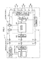
- FIG. 1 is a block diagram showing an example of an arrangement of a battery pack and a charging system incorporated with a charge control circuit in accordance with an embodiment of the invention.
- a charging system 1 shown in FIG. 1 is constituted of a battery pack 2 and a charging device 3 (a charging section).
- the charging system 1 may be constituted as a battery loaded device system such as electronic devices including a mobile personal computer, a digital camera, and a mobile phone; and vehicles including an electric vehicle and a hybrid electric vehicle, including an unillustrated load device for receiving an electric power from the battery pack 2.
- the battery pack 2 may be attached to the load device and charged through the load device, in place of the arrangement shown in FIG. 1 , wherein the battery pack 2 is charged by the charging device 3.
- the battery pack 2 includes connection terminals 11, 12, and 13, an assembled cell 14 (secondary batteries), a current detection resistor 16, a charge control circuit 4, a communication section 203, and switching elements Q1 and Q2. Further, the charge control circuit 4 has an analog-digital (A/D) converter 201, a control section 202, a voltage detection circuit 15 (a voltage detection section), and a temperature sensor 17 (a temperature detection section).
- A/D analog-digital
- the charging system 1 is not limited to the arrangement that the charging system 1 is constituted of the battery pack 2 and the charging device 3 as individual elements, but the charging system 1 as a whole may be constituted of the charge control circuit 4. Further alternatively, a part of the charge control circuit 4 may be provided in the battery pack 2, and the remainder of the charge control circuit 4 may be provided in the charging device 3. Further alternatively, the charge control circuit 4 may constitute an electric control unit (ECU) to be loaded in a vehicle, in place of the arrangement that the assembled cell 14 is provided in the battery pack 2.
- ECU electric control unit
- the charging device 3 includes connection terminals 31, 32, and 33, a control IC 34, and a charging current supply section 35.
- the control IC 34 has a communication section 36 and a control section 37.
- the charging current supply section 35 is a power source circuit for supplying a current in accordance with a control signal from the control section 37 to the battery pack 2 through the connection terminals 31 and 32.
- the control section 37 is a control circuit constituted of e.g. a microcomputer.
- the battery pack 2 and the charging device 3 are connected to each other between the connection terminals 11 and 31 on a high DC voltage side for electric power supply, between the connection terminals 13 and 33 for communication signals, and between the connection terminals 12 and 32 for electric power supply and communication signals.
- the communication sections 203 and 36 are communication interface circuits configured to transmit and receive data to and from each other through the connection terminals 13 and 33.
- the battery pack 2 is configured in such a manner that the connection terminal 11 is connected to a positive electrode of the assembled cell 14 through the switching element Q2 for a charge and the switching element Q1 for a discharge.
- P-channel field effect transistors (FETs) for instance are used as the switching elements Q1 and Q2.
- the switching element Q1 is constructed in such a manner that a cathode of a parasitic diode is aligned with a direction of the assembled cell 14.
- the switching element Q2 is constructed in such a manner that a cathode of a parasitic diode is aligned with a direction of the connection terminal 11.
- connection terminal 12 is connected to a negative electrode of the assembled cell 14 through the current detection resistor 16, and a current path from the connection terminal 11 to the connection terminal 12 through the switching elements Q2 and Q1, the assembled cell 14, and the current detection resistor 16 is defined.
- the current detection resistor 16 converts a charging current and a discharging current of the assembled cell 14 into a voltage value.
- the assembled cell 14 is constituted of e.g. plural battery blocks (secondary batteries) B1, B2, ... , and BN connected to each other in series.
- Each of the battery blocks B1, B2, ... , and BN is constituted by e.g. connecting plural secondary batteries 141 in series.
- the assembled cell 14 may be a cell e.g., may be an assembled cell constituted by connecting plural secondary batteries in parallel to each other, or may be an assembled cell constituted by connecting series-connected secondary batteries and parallel-connected secondary batteries in combination.
- the secondary battery 141 is e.g. a lithium ion secondary battery, wherein an exemplified olivine-based material i.e. LiFePO 4 is used as a positive electrode active material.
- the positive electrode active material may be e.g. LixFePO 4 (where 0 ⁇ x ⁇ 1).
- the lithium ion secondary battery using LiFePO 4 as a positive electrode active material has a flat voltage characteristic that a change in the terminal voltage is small, as compared with a change in the SOC in a wide range.
- the secondary battery 141 may be a secondary battery, wherein an amount of change in the terminal voltage is not smaller than 0.01 V but smaller than 0.3 V, in the case where the SOC is changed from 10 % to 95 %.
- a lithium ion secondary battery using LiFePO 4 as a positive electrode active material has a characteristic that an amount of decrease in the terminal voltage at the time of suspending a charge is increased, as the SOC is increased.
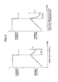
- FIG. 3 is a diagram for describing a change in the terminal voltage, in the case where a charging current is set to zero after the charging current is supplied to the secondary battery 141.
- a charging current flows, the terminal voltage of the secondary battery 141 using LiFePO 4 as a positive electrode active material is gradually increased. Then, after the charging current becomes zero, the terminal voltage is gradually decreased, and when a time "tw" has elapsed, the terminal voltage becomes a constant level and is stabilized.
- a difference ( ⁇ 2) between a terminal voltage at a point of time immediately before the charging current becomes zero, and a stabilized terminal voltage after having decreased in a condition that the secondary battery 141 is in a full charge state is larger than a corresponding difference ( ⁇ 1) in a condition that the SOC of the secondary battery 141 is small.
- the temperature sensor 17 is a temperature sensor for detecting a temperature of the assembled cell 14.
- the temperature of the assembled cell 14 is detected by the temperature sensor 17, and the detected temperature is inputted to the analog-digital converter 201 in the charge control circuit 4.
- Terminal voltages Vb1, Vb2, ... , and VbN of the battery blocks B1, B2, ... , and BN are respectively detected by the voltage detection circuit 15, and the detected terminal voltages are inputted to the analog-digital converter 201 in the charge control circuit 4.
- a current value of a charging/discharging current Ic detected by the current detection resistor 16 is also inputted to the analog-digital converter 201 in the charge control circuit 4.
- the analog-digital converter 201 converts the respective input values into digital values, and outputs the digital values to the control section 202.
- FIG. 2 is a block diagram for describing an example of an arrangement of the control section 202 shown in FIG. 1 .
- the control section 202 is constituted of e.g. a central processing unit (CPU) for executing a predetermined computation processing, a read only memory (ROM) storing a predetermined control program, a random access memory (RAM) for temporarily storing data, a timer circuit, and peripheral circuits in the periphery of these components.
- CPU central processing unit
- ROM read only memory
- RAM random access memory
- the control section 202 functions as a protection control section 211, a pre-charging section 212, a pre-charge voltage acquiring section 213, a primary charge determining section 214, a primary charge processing section 215, a charging suspend voltage acquiring section 216, a charging end determining section 217, an auxiliary charge processing section 218, an auxiliary charging suspend voltage acquiring section 219, and a recharge determining section 220 by executing the control program stored in the ROM.
- the protection control section 211 detects an anomaly in the exterior of the battery pack 2 such as a short circuit between the connection terminals 11 and 12, and an anomalous current flow from the charging device 3; and an anomaly such as an anomalous temperature rise of the assembled cell 14, based on the respective input values from the analog-digital converter 201. Specifically, for instance, if a current value detected by the current detection resistor 16 has exceeded a predetermined threshold value for anomalous current detection, it is determined that an anomaly resulting from a short circuit between the connection terminals 11 and 12 or an anomalous current flow from the charging device 3 has occurred.
- the protection control section 211 controls the switching elements Q1 and Q2 to turn off the switching elements Q1 and Q2 so as to protect the assembled cell 14 from an anomaly such as an overcurrent flow or an overheat.
- the pre-charging section 212 transmits a signal requesting a charging current of a current value Ipc (a current value for a pre-charge) which is smaller than a current value Icc (a current value for a primary charge) from the communication section 203 to the charging device 3 through the connection terminals 13 and 32, before a charge processing by the primary charge processing section 215 is performed. Accordingly, the pre-charging section 212 acquires terminal voltages Vb1, Vb2, ... , and VbN which have been detected by the voltage detection circuit 15 as third terminal voltages V3b1, V3b2, ... , and V3bN, while causing the charging device 3 to pre-charge the assembled cell 14.
- a current value Ipc a current value for a pre-charge
- Icc a current value for a primary charge
- the current value Icc is set to e.g. 0.7 C.
- the pre-charge voltage acquiring section 213 transmits a signal requesting to suspend a charge to the charging device 3, after the third terminal voltages V3b1, V3b2, ... , and V3bN have been acquired by the pre-charging section 212. Then, the pre-charge voltage acquiring section 213 acquires terminal voltages Vb1, Vb2, ... , and VbN which have been detected by the voltage detection circuit 15 in a state that the charge by the charging device 3 is suspended, as fourth terminal voltages V4b1, V4b2, ... , and V4bN.
- the primary charge determining section 214 determines whether or not a charge processing by the primary charge processing section 215 is to be performed, based on respective differences between the third terminal voltages V3b1, V3b2, ... , and V3bN acquired by the pre-charging section 212 and the fourth terminal voltages V4b1, V4b2, ... , and V4bN acquired by the pre-charge voltage acquiring section 213 with respect to each of the battery blocks B1, B2, ... , and BN.
- the primary charge processing section 215 performs a charge processing to acquire terminal voltages Vb1, Vb2, ... , and VbN detected by the voltage detection circuit 15 as first terminal voltages V1b1, Vb2, ... , and V1bN, while causing the charging device 3 to charge the assembled cell 14.
- the charging suspend voltage acquiring section 216 causes the charging device 3 to suspend the charge after the first terminal voltages V1b1, V1b2, ... , and V1bN have been acquired by the primary charge processing section 215, and acquires terminal voltages Vb1, Vb2, ... , and VbN which have been detected by the voltage detection circuit 15 as second terminal voltages V2b1, V2b2, ... , and V2bN in a state that the charge is suspended.
- the charging end determining section 217 determines whether or not the charge of the assembled cell 14 is to be terminated, based on respective differences between the first terminal voltages V1b1, V1b2, ... , and V1bN acquired by the primary charge processing section 215 and the second terminal voltages V2b1, V2b2, ... , and V2bN acquired by the charging suspend voltage acquiring section 216.
- the auxiliary charge processing section 218 performs an auxiliary charge e.g. a trickle charge, after the assembled cell 14 has been temporarily brought to a full charge state and a charge has been terminated, to compensate for a decrease in the SOC resulting from e.g. self discharging of the assembled cell 14.
- the auxiliary charge processing section 218 acquires terminal voltages Vb1, Vb2, ... , and VbN which have been detected by the voltage detection circuit 15 as fifth terminal voltages V5b1, V5b2, ... , and V5bN, while causing the charging device 3 to charge the assembled cell 14, every predetermined time interval tcyc, after the charging end determining section 217 has determined that a charge of the assembled cell 14 is to be terminated.
- the auxiliary charging suspend voltage acquiring section 219 causes the charging device 3 to suspend the charge after the fifth terminal voltages V5b1, Vb2, ... , and V5bN have been acquired by the auxiliary charge processing section 218, and acquires terminal voltages Vb1, Vb2, ... , and VbN which have been detected by the voltage detection circuit 15 as sixth terminal voltages V6b1, V6b2, ... , and V6bN in a state that a charge is suspended.
- the recharge determining section 220 determines whether or not an auxiliary charge and acquisition of the fifth terminal voltages V5b1, V5b2, ... , and V5bN by the auxiliary charge processing section 218 is to be resumed, based on respective differences between the fifth terminal voltages V5b1, Vb2, ... , and V5bN acquired by the auxiliary charge processing section 218 and the sixth terminal voltages V6b1, Vb2, ... , and V6bN acquired by the auxiliary charging suspend voltage acquiring section 219.
- the communication section 36 in the control IC 34 receives a request from the control section 202, the control section 37 in the control IC 34 controls the charging current supply section 35 to output a charging current with a voltage value and a current value in accordance with the request from the control section 202.
- the charging current supply section 35 is constituted of a switching power source circuit such as an AC-DC converter and a DC-DC converter.
- the charging current supply section 35 generates a charging voltage and a charging current designated by the control section 37, based on e.g. a voltage from a commercial AC power source, and supplies the charging voltage and the charging current to the battery pack 2 through the connection terminals 31 and 11, and the connection terminals 32 and 12.
- FIGS. 4 , 5 , and 6 are flowcharts showing an exemplified operation to be performed by the charging system shown in FIG. 1 .
- the battery blocks B1, B2, ..., and BN are generically called as a battery block B;
- the terminal voltages Vb1, Vb2, ... , and VbN are generically called as a terminal voltage Vb;
- the first terminal voltages V1b1, V1b2, ... , and V1bN are generically called as a first terminal voltage V1;
- V2bN are generically called as a second terminal voltage V2;
- the third terminal voltages V3b1, V3b2, ... , and V3bN are generically called as a third terminal voltage V3;
- the fourth terminal voltages V4b1, V4b2, ... , and V4bN are generically called as a fourth terminal voltage V4;
- the fifth terminal voltages V5b1, V5b2, ... , and V5bN are generically called as a fifth terminal voltage V5;
- the sixth terminal voltages V6b1, V6b2, ... , and V6bN are generically called as a sixth terminal voltage V6.
- the pre-charging section 212 transmits a signal requesting a charging current of the current value Ipc from the communication section 203 to the charging device 3 through the connection terminals 13 and 32.
- the charging device 3 Upon receiving the signal, the charging device 3 starts a pre-charge of the assembled cell 14 with a charging current of the current value Ipc (Step S1).
- the current value Ipc is set to a current value smaller than the current value Icc e.g. a current value of about 0.3 C.
- Step S3 the pre-charging section 212 acquires a terminal voltage Vb detected by the voltage detection section 15, as a third terminal voltage V3 (Step S3).
- the pre-charge voltage acquiring section 213 transmits a signal requesting to suspend a charge to the charging device 3, whereby the charging current is set to zero by the charging device 3, and the pre-charge is suspended (Step S4). Then, when it is determined that the state of suspending a charge by the charging device 3 is continued over a predetermined set time ⁇ (YES in Step S5), the pre-charge voltage acquiring section 213 acquires a terminal voltage Vb detected by the voltage detection section 15, as a fourth terminal voltage V4 (Step S6).
- the primary charge determining section 214 calculates respective voltage differences ⁇ V by subtracting the fourth terminal voltage V4 from the third terminal voltage V3 with respect to each of the battery blocks B1, B2, ... , and BN (Step S7). Then, the primary charge determining section 214 compares the respective voltage differences ⁇ V with a predetermined pre-determination voltage "b" (Step S8). For instance, if it is determined that any one of the voltage differences ⁇ V has exceeded the pre-determination voltage "b" (YES in Step S8), the charge is terminated to avoid an overcharge, because at least one of the battery blocks B1, B2, ... , and BN is presumed to be in a near full charge state (Step S9).
- the voltage difference ⁇ V in the secondary battery 141 in a near full charge state in the case where the charging current of the current value Ipc is supplied, is obtained by way of experiment for instance in advance, which is set as the pre-determination voltage "b".
- Step S8 If, on the other hand, it is determined in Step S8 that all the voltage differences ⁇ V are equal to or smaller than the pre-determination voltage "b" (NO in Step S8), the routine proceeds to Step S10 to perform a primary charge, because there is room for charging the assembled cell 14.
- Step S9 by performing the operations from Step S1 through Step S9, it is possible to precisely determine a charging state of the assembled cell 14 based on the voltage difference ⁇ V and to enhance the precision of charge control, even in the case where a secondary battery having a flat voltage characteristic that a change in the terminal voltage is small, as compared with a change in the SOC is charged.
- the voltage difference ⁇ V is detected by supplying a charging current of a current value smaller than the current value for a primary charge before the primary charge is performed. Accordingly, a current flowing through the assembled cell 14 is decreased, as compared with an arrangement that a primary charge in Step S10 and thereafter is performed from the start.
- the possibility that the assembled cell 14 is overcharged and is deteriorated can be reduced.
- the primary charge processing section 215 transmits a signal requesting a charging current of the current value Icc from the communication section 203 to the charging device 3 through the connection terminals 13 and 32.
- the charging device 3 starts a primary charge of charging the assembled cell 14 with a constant current of the current value Icc (Step S10).
- the primary charge processing section 215 acquires a terminal voltage Vb detected by the voltage detection section 15, as a first terminal voltage V1 (Step S11).
- the charging suspend voltage acquiring section 216 compares the first terminal voltage V1 with a predetermined determination voltage ⁇ (Step S12).
- a voltage approximate to a terminal voltage of the battery block B when the battery block B becomes a full charge state is predetermined as the determination voltage ⁇ .
- the routine proceeds to Step S11 again, whereby the primary charge is continued, because it is presumed that there is room for charging the assembled cell 14.
- Step S12 If, on the other hand, it is determined that at least one of the first terminal voltages V1b1, V1b2, ... , and V1bN has exceeded the determination voltage ⁇ (YES in Step S12), the routine proceeds to Step S 13 to more precisely determine a state of charge of the battery block B, because it is presumed that at least one of the battery blocks B1, B, ... , and BN is in a near full charge state. And, the charging suspend voltage acquiring section 216 transmits a signal requesting to suspend a charge to the charging device 3, whereby the charging current is set to zero by the charging device 3, and the primary charge is suspended (Step S13).
- the secondary battery 141 has a flat characteristic that a change in the terminal voltage is small, as compared with a change in the SOC. Accordingly, although it may be impossible to precisely determine whether or not the battery block B is in a full charge state by merely comparing the first terminal voltage V1 with the determination voltage ⁇ , it is possible to determine whether or not the battery block B is in a near full charge state. Consequently, the routine proceeds to Step S 13, only if it is determined in Step S12 that at least one of the first terminal voltages V1b1, V1b2, ..., and V1bN has exceeded the determination voltage ⁇ , and it is presumed that at least one of the battery blocks B1, B2, ... , and BN may be in a near full charge state. Thus, the possibility that a primary charge is repeatedly suspended unnecessarily is reduced. As a result, the possibility that a charging time is extended is reduced.
- the charging suspend voltage acquiring section 216 acquires a terminal voltage Vb detected by the voltage detection section 15, as a second terminal voltage V2 (Step S15).
- the charging end determining section 217 calculates respective voltage differences ⁇ V by subtracting the second terminal voltage V2 from the first terminal voltage V1 with respect to each of the battery blocks B1, B2, ... , and BN (Step S16). Then, the charging end determining section 217 compares the respective voltage differences ⁇ V with a predetermined reference voltage ⁇ (Step S 17). For instance, if it is determined that any one of the voltage differences ⁇ V has exceeded the reference voltage ⁇ (YES in Step S 17), the charge is terminated to avoid an overcharge, because it is presumed that at least one of the battery blocks B1, B2, ... , and BN is in a full charge state (Step S18). Then, the routine proceeds to Step S21 to compensate for self discharge of the assembled cell 14.
- a voltage difference ⁇ V of the secondary battery 141 in a full charge state in the case where a charging current of the current value Ipc is supplied, is obtained in advance by way of experiment for instance, which is set as the reference voltage ⁇ .
- Step S 17 If, on the other hand, it is determined in Step S 17 that all the voltage differences ⁇ V are equal to or smaller than the reference voltage ⁇ (NO in Step S 17), the routine proceeds to Step S10 to resume the primary charge, because it is presumed that there is room for charging the assembled cell 14.
- a charging state of the battery block B is determined based on the voltage difference ⁇ V. This enables to enhance precision of charge control with respect to the assembled cell 14 incorporated with the secondary batteries 141 whose change in the terminal voltage is small, as compared with a change in the SOC.
- Step S21 the auxiliary charge processing section 218 transmits a signal requesting a charging current of the current value Itc from the communication section 203 to the charging device 3 through the connection terminals 13 and 32.
- the charging device 3 Upon receiving the signal, the charging device 3 starts performing an auxiliary charge e.g. a trickle charge of the assembled cell 14 with a charging current of the current value Itc (Step S21).
- the current value Itc is set to a current value capable of compensating for a self discharging amount of the assembled cell 14 e.g. a current value of about 1/30 C.
- Step S23 the routine periodically proceeds to Step S23 every predetermined time interval tcyc, after the auxiliary charge has been started to determine the charging state of the assembled cell 14.
- the time interval tcyc is set to a time of e.g. about 10 minutes.
- the auxiliary charge processing section 218 acquires a terminal voltage Vb detected by the voltage detection circuit 15 as a fifth terminal voltage V5 (Step S23).
- the auxiliary charging suspend voltage acquiring section 219 transmits a signal requesting to suspend a charge to the charging device 3, which, in turn, sets the charging current to zero to suspend the auxiliary charge (Step S24). Then, when it is determined that the state of suspending a charge by the charging device 3 is continued over the predetermined set time ⁇ (YES in Step S25), the auxiliary charging suspend voltage acquiring section 219 acquires a terminal voltage Vb detected by the voltage detection section 15, as a sixth terminal voltage V6 (Step S26).
- the recharge determining section 220 calculates respective voltage differences ⁇ V by subtracting the sixth terminal voltage V6 from the fifth terminal voltage V5 with respect to each of the battery blocks B1, B2, ... , and BN (Step S27). Then, the recharge determining section 220 compares the respective voltage differences ⁇ V with the predetermined determination voltage ⁇ (Step S28). For instance, if it is determined that any one of the voltage differences ⁇ V has exceeded the determination voltage ⁇ (YES in Step S28), the auxiliary charge is terminated to avoid an overcharge, because at least one of the battery blocks B1, B2, ... , and BN is presumed to be in a full charge state (Step S29).
- the voltage difference ⁇ V of the secondary battery 141 in a near full charge state in the case where the charging current of the current value Ipc is supplied, is obtained in advance by way of experiment for instance, which is set as the determination voltage ⁇ .
- Step S21 If, on the other hand, it is determined that all the voltage differences ⁇ V are equal to or smaller than the determination voltage 8(NO in Step S28), the routine proceeds to Step S21 to resume the auxiliary charge, because it is presumed that there is room for charging in the assembled cell 14.
- a charge control circuit is a charge control circuit that controls a charging section which charges a secondary battery by supplying a charging current to the secondary battery, the charge control circuit comprising: a voltage detection section which detects a terminal voltage of the secondary battery; a primary charge processing section which performs a charge processing of acquiring, as a first terminal voltage, a terminal voltage detected by the voltage detection section while causing the charging section to charge the secondary battery; a charging suspend voltage acquiring section which causes the charging section to suspend the charge after the first terminal voltage has been acquired by the primary charge processing section, and acquires, as a second terminal voltage, a terminal voltage detected by the voltage detection section in a state that the charge is suspended; and a charging end determining section which determines whether or not the charge of the secondary battery is to be terminated, based on a difference between the first terminal voltage acquired by the primary charge processing section and the second terminal voltage acquired by the charging suspend voltage acquiring section.
- the primary charge processing section acquires, as a first terminal voltage, a terminals voltage of the secondary battery in a state that a charging current is supplied to the secondary battery.
- the charging suspend voltage acquiring section acquires, as a second terminal voltage, a terminal voltage of the secondary battery in a state that supply of the charging current is suspended.
- the charging end determining section determines whether or not the charge of the secondary battery is to be terminated, based on a difference between the first terminal voltage and the second terminal voltage. The difference between the first terminal voltage and the second terminal voltage is changed in accordance with the SOC of the secondary battery.
- the secondary battery may have a characteristic that an amount of decrease in the terminal voltage at the time of suspending the charge is increased as a state of charge is increased, and the charging end determining section may determine that the charge of the secondary battery is to be terminated, in the case where the difference between the first terminal voltage and the second terminal voltage has exceeded a predetermined reference voltage.
- the secondary battery may be a lithium ion secondary battery using an olivine-based material as a positive electrode active material.
- a lithium ion secondary battery using an olivine-based material as a positive electrode active material is suitable as the secondary battery, because the amount of decrease in the terminal voltage of the lithium ion secondary battery at the time of suspending a charge is increased, as the SOC is increased.
- the positive electrode active material may be LiFePO 4 .
- a lithium ion secondary battery using LiFePO 4 as a positive electrode active material is suitable as the secondary battery, because the amount of decrease in the terminal voltage of the lithium ion secondary battery at the time of suspending a charge is increased, as the SOC is increased.
- the charging suspend voltage acquiring section may acquire the second terminal voltage, when a state of suspending of the charge by the charging section has continued for a predetermined time, after the first terminal voltage has been acquired by the primary charge processing section.
- a terminal voltage of a secondary battery gradually decreases after a charge is suspended, and a certain time is required until the terminal voltage is stabilized at a constant voltage.
- the charging suspend voltage acquiring section acquires the second terminal voltage, when a state of suspending of the charge by the charging section has continued for a predetermined time. Accordingly, it is possible to acquire the second terminal voltage after the terminal voltage of the secondary battery is stabilized, and hence, it is possible to enhance precision of the second terminal voltage.
- the charging suspend voltage acquiring section may cause the charging section to suspend the charge and acquire the second terminal voltage, when the first terminal voltage is acquired by the primary charge processing section and the terminal voltage detected by the voltage detection section exceeds a determination voltage predetermined as a voltage indicating that the secondary battery is in a near full charge state.
- the charge is suspended only if the terminal voltage of the secondary battery has exceeded a determination voltage, and the secondary battery is presumed to be in a near full charge state, and then, charge control based on a difference between the first terminal voltage and the second terminal voltage is performed.
- a charge is suspended only if it is roughly determined that the secondary battery is in a near full charge state by a low-precision determination method based on a terminal voltage of the secondary battery. Accordingly, the possibility that a charge is suspended unnecessarily and a charging time is extended is reduced.
- the primary charge processing section may cause the charging section to supply a charging current of a predetermined current value for a primary charge to the secondary battery to charge the secondary battery with a constant current in performing the charge processing
- the charge control circuit may further comprise: a pre-charging section which acquires, as a third terminal voltage, a terminal voltage detected by the voltage detection section while causing the charging section to charge the secondary battery with a charging current of a current value for a pre-charge smaller than the current value for the primary charge, before the charge processing is performed by the primary charge processing section; a pre-charge voltage acquiring section which causes the charging section to suspend the charge after the third terminal voltage has been acquired by the pre-charging section, and acquires, as a fourth terminal voltage, a terminal voltage detected by the voltage detection section in a state that the charging by the charging section is suspended; and a primary charge determining section which determines whether or not the charge processing by the primary charge processing section is to be performed, based on a difference between the third terminal voltage acquired by the pre-charging section and
- the pre-charging section acquires, as a third terminal voltage, a terminal voltage of the secondary battery in a state that a charging current of a current value for a pre-charge smaller than the current value for the primary charge is supplied to the secondary battery, before the charge processing by the primary charge processing section is performed. Further, the pre-charge voltage acquiring section acquires, as a fourth terminal voltage, a terminal voltage of the secondary battery in a state that supply of the charging current is suspended. Further, the primary charge determining section determines whether or not the primary charge by the primary charge processing section is to be performed, based on a difference between the third terminal voltage and the fourth terminal voltage.
- the primary charge processing section may cause the charging section to supply a charging current of a predetermined current value for a primary charge to the secondary battery to charge the secondary battery with a constant current in performing the charge processing
- the charge control circuit may further comprise: an auxiliary charge processing section which performs an auxiliary charge processing of causing the charging section to charge the secondary battery with a charging current of a current value smaller than the current value for the primary charge and acquiring, as a fifth terminal voltage, a terminal voltage detected by the voltage detection section every predetermined time interval, after the charge of the secondary battery has been determined to be terminated by the charging end determining section; an auxiliary charging suspend voltage acquiring section which causes the charging section to suspend the charge after the fifth terminal voltage has been acquired by the auxiliary charge processing section, and acquires, as a sixth terminal voltage, a terminal voltage detected by the voltage detection section in a state that the charge by the charging section is suspended; and a recharge determining section which determines whether or not the auxiliary charge processing by the auxiliary charge processing section is to be resumed, based
- a decrease of the charging amount resulting from discharging of the secondary battery is compensated, by charging the secondary battery with a charging current of a current value smaller than the current value for the primary charge, after the charging end determining section has determined that the charge of the secondary battery is to be terminated.
- the auxiliary charge processing section acquires, as a fifth terminal voltage, a terminal voltage of the secondary battery periodically every predetermined time interval in a state that the charging current is supplied to the secondary battery.
- the auxiliary charging suspend voltage acquiring section acquires, as a sixth terminal voltage, a terminal voltage of the secondary battery in a state that supply of the charging current is suspended.
- the recharge determining section determines whether or not the auxiliary charge is to be resumed, based on a difference between the fifth terminal voltage and the sixth terminal voltage. Accordingly, it is possible to enhance precision of charge control, as compared with charge control based on an SOC which is directly converted from a terminal voltage, to suppress the possibility of overcharge of the secondary battery by an auxiliary charge processing.
- a charging device includes the charge control circuit described above, and the charging section.
- a battery pack according to an aspect of the invention includes the charge control circuit described above, and the secondary battery.
- the invention is suitably applicable to a charge control circuit that controls a charge of a secondary battery, and a battery pack and a charging system incorporated with the charge control circuit in a battery loaded device such as electronic devices including a mobile personal computer, a digital camera, and a mobile phone; vehicles including an electric vehicle and a hybrid electric vehicle; and a power source system, wherein a photovoltaic cell or a power generating device is used in combination with a secondary battery.
- a battery loaded device such as electronic devices including a mobile personal computer, a digital camera, and a mobile phone; vehicles including an electric vehicle and a hybrid electric vehicle; and a power source system, wherein a photovoltaic cell or a power generating device is used in combination with a secondary battery.
Landscapes
- Engineering & Computer Science (AREA)
- Chemical & Material Sciences (AREA)
- General Chemical & Material Sciences (AREA)
- Chemical Kinetics & Catalysis (AREA)
- Electrochemistry (AREA)
- Power Engineering (AREA)
- Manufacturing & Machinery (AREA)
- Life Sciences & Earth Sciences (AREA)
- Sustainable Development (AREA)
- Sustainable Energy (AREA)
- Materials Engineering (AREA)
- Secondary Cells (AREA)
- Charge And Discharge Circuits For Batteries Or The Like (AREA)
Abstract
A charge control circuit that controls a charging section which charges a secondary battery by supplying a charging current to the secondary battery. The charge control circuit includes a voltage detection section which detects a terminal voltage of the secondary battery; a primary charge processing section which performs a charge processing of acquiring, as a first terminal voltage, a terminal voltage detected by the voltage detection section while causing the charging section to charge the secondary battery; a charging suspend voltage acquiring section which causes the charging section to suspend the charge after the first terminal voltage has been acquired by the primary charge processing section, and acquires, as a second terminal voltage, a terminal voltage detected by the voltage detection section in a state that the charge is suspended; and a charging end determining section which determiners whether or not the charge of the secondary battery is to be terminated, based on a difference between the first terminal voltage acquired by the primary charge processing section and the second terminal voltage acquired by the charging suspend voltage acquiring section.
Description
- The invention relates to a charge control circuit that controls a charge of a secondary battery, and a charging device and a battery pack incorporated with the same.
- In recent years, a secondary battery is widely used as a power source system in cooperation with a photovoltaic cell or a power generating device. The power generating device is driven by a natural energy such as a wind power or a hydraulic power, or an artificial power such as internal combustion engine. The power source system incorporated with the secondary battery is configured in such a manner that a surplus electric power is accumulated in the secondary battery, and an electric power is supplied from the secondary battery when a load device requires an electric power to thereby enhance the energy efficiency.
- An example of the power source system is a photovoltaic power generating system. The photovoltaic power generating system is configured in such a manner that a secondary battery is charged with a surplus electric power, in the case where the amount of electric power to be generated by the sunlight is larger than the electric power consumption of a load device. Conversely, in the case where the amount of electric power to be generated by the sunlight is smaller than the electric power consumption of a load device, an electric power is outputted from the secondary battery to compensate for the shortage of electric power to drive the load device.
- As described above, since a surplus electric power which has not been conventionally used can be accumulated in a secondary battery, the photovoltaic power generating system is advantageous in enhancing the energy efficiency, as compared with a conventional power source system which does not use a secondary battery.
- In such a photovoltaic power generating system, if a secondary battery is in a full charge state, it is impossible to charge a surplus electric power, which causes electric power loss. In view of this, charge control is performed so that a state of charge (hereinafter, called as SOC) of a secondary battery does not reach 100 % in order to efficiently charge the secondary battery with a surplus electric power. Charge control is also performed to keep the SOC from becoming zero so as to be able to drive a load device when needed. Specifically, charge control is normally performed in such a manner that the SOC is kept in the range from 20 % to 80%.
- A hybrid electric vehicle (HEV) loaded with an engine and a motor also utilizes the above principle. The HEV is configured in such a manner that a power generator is driven by a surplus output of the engine to charge a secondary battery, in the case where the output from the engine is large as compared with a power required for driving the HEV. The HEV is also configured in such a manner that the secondary battery is charged by using the motor as a power generator at the time of braking or decelerating the vehicle.
- A load leveling power source or a plug-in hybrid vehicle effectively utilizing the nighttime electric power has also attracted attention in recent years. The load leveling power source is a system, wherein an electric power is stored in a secondary battery during the nighttime when the electric power consumption is small and the electricity rate is low, and the stored electric power is used during the daytime when the electric power consumption reaches its highest peak. The system is proposed to make the electric power generation amount constant by making the electric power consumption amount uniform, thereby contributing to efficient utilization of an electric power facility and reduction of the facility investment.
- The plug-in hybrid vehicle is proposed to reduce the total CO2 emission, utilizing nighttime electric power. Specifically, the plug-in hybrid vehicle primarily performs EV driving of supplying an electric power from a secondary battery while driving an urban area where the gasoline mileage is low, and performs HEV driving of using both an engine and a motor during a long distance driving.
- Incidentally, a secondary battery is degraded and the capacity thereof is reduced, as it is used. Accordingly, it is important to accurately determine the SOC of the secondary battery. For instance, if one fails to accurately determine the SOC of a secondary battery, and the secondary battery is overcharged, the long-term reliability such as the life of the secondary battery may be impaired. In view of this, it is necessary to precisely determine the SOC of a secondary battery in use, particularly, determine whether or not the secondary battery is in a near full charge state to perform charge control.
-
FIG. 7 is a graph showing a relation between an SOC and a terminal voltage of a secondary battery. InFIG. 7 , the axis of abscissas denotes an SOC, and the axis of ordinate denotes a terminal voltage of a secondary battery in a non-load state, in other words, an open circuit voltage (OCV). As shown by the graph G1 inFIG. 7 , a terminal voltage of a secondary battery is increased, as charging progresses and the SOC is increased, generally. Consequently, the SOC is detected by converting a terminal voltage of a secondary battery into the SOC, utilizing the characteristic as shown in the graph G1, conventionally. - However, as shown by the graph G2 in
FIG. 7 for instance, some of the secondary batteries have a flat voltage characteristic that a change in the terminal voltage is small, as compared with a change in the SOC. In case of a secondary battery whose change in the terminal voltage is flat as compared with a change in the SOC au just described, the terminal voltage is moderately changed as compared with a change in the SOC. Accordingly, detecting the SOC based on the terminal voltage may result in lowering detection precision of the SOC. If charge control is performed based on the SOC having a low detection precision, there has been a problem that it is impossible to properly charge the secondary battery. - For instance, there may be a case that the SOC is erroneously determined to be 80 %, despite that the SOC is actually 20 %. In such a case, since the SOC is erroneously determined, charging is not performed, despite that discharging progresses and the SOC is becoming lowered. As a result, charging becomes insufficient, the dischargeable time is reduced, and the battery cannot deliver its performance fully. Conversely, there may be a case that the SOC is erroneously determined to be 20 %, despite that the SOC is actually 80 %. In such a case, extra charging is performed in excess of a full charge state, and there is a possibility that overcharge is performed. In that event, the life and the reliability of the battery may be impaired.
- In order to solve the problems, there is proposed e.g. a method for easily detecting the SOC of a battery by using positive electrode materials of two or more kinds in a mixed state for enhancing detection precision of the SOC (see e.g. patent literature 1). The publication discloses that having two or more kinds of quasi-flat voltage portions of different voltage levels is advantageous in enhancing detection precision of the SOC. When there are a large number of quasi-flat voltage portions of different voltage levels, the gradient of a charging voltage is apparently large as compared with a change in the SOC in broad perspective.
- However, in the technology disclosed in
patent literature 1, since positive electrode materials of two or more kinds are used to enhance detection precision of the SOC, a battery characteristic is varied as compared with a secondary battery using a positive electrode material of one kind. As a result, it may be impossible or difficult to obtain an intended battery characteristic. - [Patent Literature 1]
JP-A-2007-250299 - The invention is made in view of the above, and an object of the invention is to provide a charge control circuit that enables to enhance precision of charge control with respect to a secondary battery having a small change in a terminal voltage, as compared with a change in an SOC, and a charging device and a battery pack incorporated with the charge control circuit
- A charge control circuit according to an aspect of the invention is a charge control circuit that controls a charging section which charges a secondary battery by supplying a charging current to the secondary battery, the charge control circuit comprising: a voltage detection section which detects a terminal voltage of the secondary battery; a primary charge processing section which performs a charge processing of acquiring, as a first terminal voltage, a terminal voltage detected by the voltage detection section while causing the charging section to charge the secondary battery; a charging suspend voltage acquiring section which causes the charging section to suspend the charge after the first terminal voltage has been acquired by the primary charge processing section, and acquires, as a second terminal voltage, a terminal voltage detected by the voltage detection section in a state that the charge is suspended; and a charging end determining section which determines whether or not the charge of the secondary battery is to be terminated, based on a difference between the first terminal voltage acquired by the primary charge processing section and the second terminal voltage acquired by the charging suspend voltage acquiring section.
- In the above arrangement, the primary charge processing section acquires, as a first terminal voltage, a terminal voltage of the secondary battery in a state that a charging current is supplied to the secondary battery. The charging suspend voltage acquiring section acquires, as a second terminal voltage, a terminal voltage of the secondary battery in a state that supply of the charging current is suspended. The charging end determining section determines whether or not the charge of the secondary battery is to be terminated, based on a difference between the first terminal voltage and the second terminal voltage. The difference between the first terminal voltage and the second terminal voltage is changed in accordance with the SOC of the secondary battery. Accordingly, even if a secondary battery having a small change in the terminal voltage, as compared with a change in the SOC is used, it is possible to enhance precision of charge control, as compared with charge control based on an SOC which is directly converted from a terminal voltage, by determining whether or not the charge is to be terminated based on a difference between the first terminal voltage and the second terminal voltage.
- A charging device according to an aspect of the invention includes the aforementioned charge control circuit, and the charging section.
- In the above arrangement, it is possible to provide the charging device with enhanced precision of charge control with respect to a secondary battery having a small change in the terminal voltage, as compared with a change in the SOC.
- A battery pack according to an aspect of the invention includes the aforementioned charge control circuit, and the secondary battery.
- In the above arrangement, it is possible to provide the battery pack with enhanced precision of charge control with respect to a secondary battery having a small change in the terminal voltage, as compared with a change in the SOC.
-
-
FIG. 1 is a block diagram showing an example of an arrangement of a battery pack and a charging system incorporated with a charge control circuit in accordance with an embodiment of the invention. -
FIG. 2 is a block diagram for describing an example of an arrangement of a control section shown inFIG. 1 . -
FIG. 3 is a diagram for describing a change in a terminal voltage, in the case where a charging current is set to zero after the charging current is supplied to a secondary battery shown inFIG. 1 . -
FIG. 4 is a flowchart showing an example of an operation to be performed by the charging system shown inFIG. 1 . -
FIG. 5 is a flowchart showing an example of an operation to be performed by the charging system shown inFIG. 1 . -
FIG. 6 is a flowchart showing an example of an operation to be performed by the charging system shown inFIG. 1 . -
FIG. 7 is a graph showing a relation between an SOC and a terminal voltage of a secondary battery. - In the following, an embodiment of the invention is described referring to the accompanying drawings. Elements having the same reference numerals throughout the drawings have the same arrangements, and repeated description thereof is omitted herein.
FIG. 1 is a block diagram showing an example of an arrangement of a battery pack and a charging system incorporated with a charge control circuit in accordance with an embodiment of the invention. A chargingsystem 1 shown inFIG. 1 is constituted of abattery pack 2 and a charging device 3 (a charging section). - The
charging system 1 may be constituted as a battery loaded device system such as electronic devices including a mobile personal computer, a digital camera, and a mobile phone; and vehicles including an electric vehicle and a hybrid electric vehicle, including an unillustrated load device for receiving an electric power from thebattery pack 2. In the above arrangement, thebattery pack 2 may be attached to the load device and charged through the load device, in place of the arrangement shown inFIG. 1 , wherein thebattery pack 2 is charged by the chargingdevice 3. - The
battery pack 2 includesconnection terminals current detection resistor 16, acharge control circuit 4, acommunication section 203, and switching elements Q1 and Q2. Further, thecharge control circuit 4 has an analog-digital (A/D)converter 201, acontrol section 202, a voltage detection circuit 15 (a voltage detection section), and a temperature sensor 17 (a temperature detection section). - The
charging system 1 is not limited to the arrangement that thecharging system 1 is constituted of thebattery pack 2 and thecharging device 3 as individual elements, but thecharging system 1 as a whole may be constituted of thecharge control circuit 4. Further alternatively, a part of thecharge control circuit 4 may be provided in thebattery pack 2, and the remainder of thecharge control circuit 4 may be provided in thecharging device 3. Further alternatively, thecharge control circuit 4 may constitute an electric control unit (ECU) to be loaded in a vehicle, in place of the arrangement that the assembledcell 14 is provided in thebattery pack 2. - The charging
device 3 includesconnection terminals control IC 34, and a chargingcurrent supply section 35. Thecontrol IC 34 has acommunication section 36 and acontrol section 37. The chargingcurrent supply section 35 is a power source circuit for supplying a current in accordance with a control signal from thecontrol section 37 to thebattery pack 2 through theconnection terminals control section 37 is a control circuit constituted of e.g. a microcomputer. - The
battery pack 2 and thecharging device 3 are connected to each other between theconnection terminals connection terminals connection terminals communication sections connection terminals - The
battery pack 2 is configured in such a manner that theconnection terminal 11 is connected to a positive electrode of the assembledcell 14 through the switching element Q2 for a charge and the switching element Q1 for a discharge. P-channel field effect transistors (FETs) for instance are used as the switching elements Q1 and Q2. The switching element Q1 is constructed in such a manner that a cathode of a parasitic diode is aligned with a direction of the assembledcell 14. The switching element Q2 is constructed in such a manner that a cathode of a parasitic diode is aligned with a direction of theconnection terminal 11. - The
connection terminal 12 is connected to a negative electrode of the assembledcell 14 through thecurrent detection resistor 16, and a current path from theconnection terminal 11 to theconnection terminal 12 through the switching elements Q2 and Q1, the assembledcell 14, and thecurrent detection resistor 16 is defined. Thecurrent detection resistor 16 converts a charging current and a discharging current of the assembledcell 14 into a voltage value. - The assembled
cell 14 is constituted of e.g. plural battery blocks (secondary batteries) B1, B2, ... , and BN connected to each other in series. Each of the battery blocks B1, B2, ... , and BN is constituted by e.g. connecting pluralsecondary batteries 141 in series. Alternatively, the assembledcell 14 may be a cell e.g., may be an assembled cell constituted by connecting plural secondary batteries in parallel to each other, or may be an assembled cell constituted by connecting series-connected secondary batteries and parallel-connected secondary batteries in combination. - The
secondary battery 141 is e.g. a lithium ion secondary battery, wherein an exemplified olivine-based material i.e. LiFePO4 is used as a positive electrode active material. The positive electrode active material may be e.g. LixFePO4 (where 0<x≤1). - As shown by e.g. the graph G2 in
FIG. 7 , the lithium ion secondary battery using LiFePO4 as a positive electrode active material has a flat voltage characteristic that a change in the terminal voltage is small, as compared with a change in the SOC in a wide range. For instance, thesecondary battery 141 may be a secondary battery, wherein an amount of change in the terminal voltage is not smaller than 0.01 V but smaller than 0.3 V, in the case where the SOC is changed from 10 % to 95 %. - The inventors of the present application have found through the experiments that, as shown in
FIG. 3 , a lithium ion secondary battery using LiFePO4 as a positive electrode active material has a characteristic that an amount of decrease in the terminal voltage at the time of suspending a charge is increased, as the SOC is increased. -
FIG. 3 is a diagram for describing a change in the terminal voltage, in the case where a charging current is set to zero after the charging current is supplied to thesecondary battery 141. As shown inFIG. 3 , as a charging current flows, the terminal voltage of thesecondary battery 141 using LiFePO4 as a positive electrode active material is gradually increased. Then, after the charging current becomes zero, the terminal voltage is gradually decreased, and when a time "tw" has elapsed, the terminal voltage becomes a constant level and is stabilized. - The inventors of the application have found through the experiments that a difference (Δ2) between a terminal voltage at a point of time immediately before the charging current becomes zero, and a stabilized terminal voltage after having decreased in a condition that the
secondary battery 141 is in a full charge state is larger than a corresponding difference (Δ1) in a condition that the SOC of thesecondary battery 141 is small. - The
temperature sensor 17 is a temperature sensor for detecting a temperature of the assembledcell 14. The temperature of the assembledcell 14 is detected by thetemperature sensor 17, and the detected temperature is inputted to the analog-digital converter 201 in thecharge control circuit 4. Terminal voltages Vb1, Vb2, ... , and VbN of the battery blocks B1, B2, ... , and BN are respectively detected by thevoltage detection circuit 15, and the detected terminal voltages are inputted to the analog-digital converter 201 in thecharge control circuit 4. - A current value of a charging/discharging current Ic detected by the
current detection resistor 16 is also inputted to the analog-digital converter 201 in thecharge control circuit 4. The analog-digital converter 201 converts the respective input values into digital values, and outputs the digital values to thecontrol section 202. -
FIG. 2 is a block diagram for describing an example of an arrangement of thecontrol section 202 shown inFIG. 1 . Thecontrol section 202 is constituted of e.g. a central processing unit (CPU) for executing a predetermined computation processing, a read only memory (ROM) storing a predetermined control program, a random access memory (RAM) for temporarily storing data, a timer circuit, and peripheral circuits in the periphery of these components. Thecontrol section 202 functions as aprotection control section 211, apre-charging section 212, a pre-chargevoltage acquiring section 213, a primarycharge determining section 214, a primarycharge processing section 215, a charging suspendvoltage acquiring section 216, a chargingend determining section 217, an auxiliarycharge processing section 218, an auxiliary charging suspendvoltage acquiring section 219, and arecharge determining section 220 by executing the control program stored in the ROM. - The
protection control section 211 detects an anomaly in the exterior of thebattery pack 2 such as a short circuit between theconnection terminals device 3; and an anomaly such as an anomalous temperature rise of the assembledcell 14, based on the respective input values from the analog-digital converter 201. Specifically, for instance, if a current value detected by thecurrent detection resistor 16 has exceeded a predetermined threshold value for anomalous current detection, it is determined that an anomaly resulting from a short circuit between theconnection terminals device 3 has occurred. Further, for instance, if a temperature of the assembledcell 14 detected by thetemperature sensor 17 has exceeded a predetermined threshold value for detecting an anomalous temperature rise, it is determined that an anomaly has occurred in the assembledcell 14. In the case where such an anomaly has been detected, theprotection control section 211 controls the switching elements Q1 and Q2 to turn off the switching elements Q1 and Q2 so as to protect the assembledcell 14 from an anomaly such as an overcurrent flow or an overheat. - The
pre-charging section 212 transmits a signal requesting a charging current of a current value Ipc (a current value for a pre-charge) which is smaller than a current value Icc (a current value for a primary charge) from thecommunication section 203 to thecharging device 3 through theconnection terminals charge processing section 215 is performed. Accordingly, thepre-charging section 212 acquires terminal voltages Vb1, Vb2, ... , and VbN which have been detected by thevoltage detection circuit 15 as third terminal voltages V3b1, V3b2, ... , and V3bN, while causing thecharging device 3 to pre-charge the assembledcell 14. - Here, a current value where the remaining capacity of the
secondary battery 141 having a nominal capacity value becomes zero one hour after thesecondary battery 141 has been discharged with a constant current is defined as 1 C (= 1 It = battery capacity (Ah)/1(h)). The current value Icc is set to e.g. 0.7 C. - The pre-charge
voltage acquiring section 213 transmits a signal requesting to suspend a charge to thecharging device 3, after the third terminal voltages V3b1, V3b2, ... , and V3bN have been acquired by thepre-charging section 212. Then, the pre-chargevoltage acquiring section 213 acquires terminal voltages Vb1, Vb2, ... , and VbN which have been detected by thevoltage detection circuit 15 in a state that the charge by the chargingdevice 3 is suspended, as fourth terminal voltages V4b1, V4b2, ... , and V4bN. - The primary
charge determining section 214 determines whether or not a charge processing by the primarycharge processing section 215 is to be performed, based on respective differences between the third terminal voltages V3b1, V3b2, ... , and V3bN acquired by thepre-charging section 212 and the fourth terminal voltages V4b1, V4b2, ... , and V4bN acquired by the pre-chargevoltage acquiring section 213 with respect to each of the battery blocks B1, B2, ... , and BN. - The primary
charge processing section 215 performs a charge processing to acquire terminal voltages Vb1, Vb2, ... , and VbN detected by thevoltage detection circuit 15 as first terminal voltages V1b1, Vb2, ... , and V1bN, while causing thecharging device 3 to charge the assembledcell 14. - The charging suspend
voltage acquiring section 216 causes thecharging device 3 to suspend the charge after the first terminal voltages V1b1, V1b2, ... , and V1bN have been acquired by the primarycharge processing section 215, and acquires terminal voltages Vb1, Vb2, ... , and VbN which have been detected by thevoltage detection circuit 15 as second terminal voltages V2b1, V2b2, ... , and V2bN in a state that the charge is suspended. - The charging
end determining section 217 determines whether or not the charge of the assembledcell 14 is to be terminated, based on respective differences between the first terminal voltages V1b1, V1b2, ... , and V1bN acquired by the primarycharge processing section 215 and the second terminal voltages V2b1, V2b2, ... , and V2bN acquired by the charging suspendvoltage acquiring section 216. - The auxiliary
charge processing section 218 performs an auxiliary charge e.g. a trickle charge, after the assembledcell 14 has been temporarily brought to a full charge state and a charge has been terminated, to compensate for a decrease in the SOC resulting from e.g. self discharging of the assembledcell 14. Specifically, the auxiliarycharge processing section 218 acquires terminal voltages Vb1, Vb2, ... , and VbN which have been detected by thevoltage detection circuit 15 as fifth terminal voltages V5b1, V5b2, ... , and V5bN, while causing thecharging device 3 to charge the assembledcell 14, every predetermined time interval tcyc, after the chargingend determining section 217 has determined that a charge of the assembledcell 14 is to be terminated. - The auxiliary charging suspend
voltage acquiring section 219 causes thecharging device 3 to suspend the charge after the fifth terminal voltages V5b1, Vb2, ... , and V5bN have been acquired by the auxiliarycharge processing section 218, and acquires terminal voltages Vb1, Vb2, ... , and VbN which have been detected by thevoltage detection circuit 15 as sixth terminal voltages V6b1, V6b2, ... , and V6bN in a state that a charge is suspended. - The
recharge determining section 220 determines whether or not an auxiliary charge and acquisition of the fifth terminal voltages V5b1, V5b2, ... , and V5bN by the auxiliarycharge processing section 218 is to be resumed, based on respective differences between the fifth terminal voltages V5b1, Vb2, ... , and V5bN acquired by the auxiliarycharge processing section 218 and the sixth terminal voltages V6b1, Vb2, ... , and V6bN acquired by the auxiliary charging suspendvoltage acquiring section 219. - In the
charging device 3, thecommunication section 36 in thecontrol IC 34 receives a request from thecontrol section 202, thecontrol section 37 in thecontrol IC 34 controls the chargingcurrent supply section 35 to output a charging current with a voltage value and a current value in accordance with the request from thecontrol section 202. The chargingcurrent supply section 35 is constituted of a switching power source circuit such as an AC-DC converter and a DC-DC converter. The chargingcurrent supply section 35 generates a charging voltage and a charging current designated by thecontrol section 37, based on e.g. a voltage from a commercial AC power source, and supplies the charging voltage and the charging current to thebattery pack 2 through theconnection terminals connection terminals - Next, an operation to be performed by the charging system having the above configuration is described.
FIGS. 4 ,5 , and6 are flowcharts showing an exemplified operation to be performed by the charging system shown inFIG. 1 . In the following description, the battery blocks B1, B2, ..., and BN are generically called as a battery block B; the terminal voltages Vb1, Vb2, ... , and VbN are generically called as a terminal voltage Vb; the first terminal voltages V1b1, V1b2, ... , and V1bN are generically called as a first terminal voltage V1; the second terminal voltages V2b1, V2b2, ... , and V2bN are generically called as a second terminal voltage V2; the third terminal voltages V3b1, V3b2, ... , and V3bN are generically called as a third terminal voltage V3; the fourth terminal voltages V4b1, V4b2, ... , and V4bN are generically called as a fourth terminal voltage V4; the fifth terminal voltages V5b1, V5b2, ... , and V5bN are generically called as a fifth terminal voltage V5; and the sixth terminal voltages V6b1, V6b2, ... , and V6bN are generically called as a sixth terminal voltage V6. - When a charge of the assembled
cell 14 is started, thepre-charging section 212 transmits a signal requesting a charging current of the current value Ipc from thecommunication section 203 to thecharging device 3 through theconnection terminals device 3 starts a pre-charge of the assembledcell 14 with a charging current of the current value Ipc (Step S1). The current value Ipc is set to a current value smaller than the current value Icc e.g. a current value of about 0.3 C. - Then, upon lapse of a predetermined time "a", e.g. three minutes after the pre-charge has been started (YES in Step S2), the
pre-charging section 212 acquires a terminal voltage Vb detected by thevoltage detection section 15, as a third terminal voltage V3 (Step S3). - Then, the pre-charge
voltage acquiring section 213 transmits a signal requesting to suspend a charge to thecharging device 3, whereby the charging current is set to zero by the chargingdevice 3, and the pre-charge is suspended (Step S4). Then, when it is determined that the state of suspending a charge by the chargingdevice 3 is continued over a predetermined set time β (YES in Step S5), the pre-chargevoltage acquiring section 213 acquires a terminal voltage Vb detected by thevoltage detection section 15, as a fourth terminal voltage V4 (Step S6). - A time equal to or longer than the time "tw" corresponding to a time duration from a point of time when the charging current becomes zero to a point of time when the terminal voltage Vb is stabilized, is predetermined as the set time β. Since the fourth terminal voltage V4 (and the second terminal voltage V2 and the sixth terminal voltage V6 to be described later) is acquired after the terminal voltage Vb has been stabilized, precision of the fourth terminal voltage V4 (and the second terminal voltage V2 and the sixth terminal voltage V6 to be described later) is enhanced.
- Then, the primary
charge determining section 214 calculates respective voltage differences ΔV by subtracting the fourth terminal voltage V4 from the third terminal voltage V3 with respect to each of the battery blocks B1, B2, ... , and BN (Step S7). Then, the primarycharge determining section 214 compares the respective voltage differences ΔV with a predetermined pre-determination voltage "b" (Step S8). For instance, if it is determined that any one of the voltage differences ΔV has exceeded the pre-determination voltage "b" (YES in Step S8), the charge is terminated to avoid an overcharge, because at least one of the battery blocks B1, B2, ... , and BN is presumed to be in a near full charge state (Step S9). The voltage difference ΔV in thesecondary battery 141 in a near full charge state in the case where the charging current of the current value Ipc is supplied, is obtained by way of experiment for instance in advance, which is set as the pre-determination voltage "b". - If, on the other hand, it is determined in Step S8 that all the voltage differences ΔV are equal to or smaller than the pre-determination voltage "b" (NO in Step S8), the routine proceeds to Step S10 to perform a primary charge, because there is room for charging the assembled
cell 14. - As described above, by performing the operations from Step S1 through Step S9, it is possible to precisely determine a charging state of the assembled
cell 14 based on the voltage difference ΔV and to enhance the precision of charge control, even in the case where a secondary battery having a flat voltage characteristic that a change in the terminal voltage is small, as compared with a change in the SOC is charged. Further, the voltage difference ΔV is detected by supplying a charging current of a current value smaller than the current value for a primary charge before the primary charge is performed. Accordingly, a current flowing through the assembledcell 14 is decreased, as compared with an arrangement that a primary charge in Step S10 and thereafter is performed from the start. As a result, even in the case where the assembledcell 14 is already in a full charge state at the time of starting a charge, the possibility that the assembledcell 14 is overcharged and is deteriorated can be reduced. - Then, the primary
charge processing section 215 transmits a signal requesting a charging current of the current value Icc from thecommunication section 203 to thecharging device 3 through theconnection terminals device 3 starts a primary charge of charging the assembledcell 14 with a constant current of the current value Icc (Step S10). Then, the primarycharge processing section 215 acquires a terminal voltage Vb detected by thevoltage detection section 15, as a first terminal voltage V1 (Step S11). - Then, the charging suspend
voltage acquiring section 216 compares the first terminal voltage V1 with a predetermined determination voltage α (Step S12). A voltage approximate to a terminal voltage of the battery block B when the battery block B becomes a full charge state is predetermined as the determination voltage α. And, if it is determined that all the first terminal voltages V1b1, V1b2, ..., and V1bN are equal to or smaller than the determination voltage α (NO in Step S12), the routine proceeds to Step S11 again, whereby the primary charge is continued, because it is presumed that there is room for charging the assembledcell 14. - If, on the other hand, it is determined that at least one of the first terminal voltages V1b1, V1b2, ... , and V1bN has exceeded the determination voltage α (YES in Step S12), the routine proceeds to Step
S 13 to more precisely determine a state of charge of the battery block B, because it is presumed that at least one of the battery blocks B1, B, ... , and BN is in a near full charge state. And, the charging suspendvoltage acquiring section 216 transmits a signal requesting to suspend a charge to thecharging device 3, whereby the charging current is set to zero by the chargingdevice 3, and the primary charge is suspended (Step S13). - The
secondary battery 141 has a flat characteristic that a change in the terminal voltage is small, as compared with a change in the SOC. Accordingly, although it may be impossible to precisely determine whether or not the battery block B is in a full charge state by merely comparing the first terminal voltage V1 with the determination voltage α, it is possible to determine whether or not the battery block B is in a near full charge state. Consequently, the routine proceeds to StepS 13, only if it is determined in Step S12 that at least one of the first terminal voltages V1b1, V1b2, ..., and V1bN has exceeded the determination voltage α, and it is presumed that at least one of the battery blocks B1, B2, ... , and BN may be in a near full charge state. Thus, the possibility that a primary charge is repeatedly suspended unnecessarily is reduced. As a result, the possibility that a charging time is extended is reduced. - Then, if it is determined that the state of suspending a charge by the charging
device 3 is continued over the predetermined set time β (YES in Step S 14), the charging suspendvoltage acquiring section 216 acquires a terminal voltage Vb detected by thevoltage detection section 15, as a second terminal voltage V2 (Step S15). - Then, the charging
end determining section 217 calculates respective voltage differences ΔV by subtracting the second terminal voltage V2 from the first terminal voltage V1 with respect to each of the battery blocks B1, B2, ... , and BN (Step S16). Then, the chargingend determining section 217 compares the respective voltage differences ΔV with a predetermined reference voltage γ (Step S 17). For instance, if it is determined that any one of the voltage differences ΔV has exceeded the reference voltage γ (YES in Step S 17), the charge is terminated to avoid an overcharge, because it is presumed that at least one of the battery blocks B1, B2, ... , and BN is in a full charge state (Step S18). Then, the routine proceeds to Step S21 to compensate for self discharge of the assembledcell 14. - A voltage difference ΔV of the
secondary battery 141 in a full charge state in the case where a charging current of the current value Ipc is supplied, is obtained in advance by way of experiment for instance, which is set as the reference voltage γ. - If, on the other hand, it is determined in
Step S 17 that all the voltage differences ΔV are equal to or smaller than the reference voltage γ (NO in Step S 17), the routine proceeds to Step S10 to resume the primary charge, because it is presumed that there is room for charging the assembledcell 14. - As described above, by performing the operations from Steps S10 through S18, a charging state of the battery block B is determined based on the voltage difference ΔV. This enables to enhance precision of charge control with respect to the assembled
cell 14 incorporated with thesecondary batteries 141 whose change in the terminal voltage is small, as compared with a change in the SOC. - Then, in Step S21, the auxiliary
charge processing section 218 transmits a signal requesting a charging current of the current value Itc from thecommunication section 203 to thecharging device 3 through theconnection terminals device 3 starts performing an auxiliary charge e.g. a trickle charge of the assembledcell 14 with a charging current of the current value Itc (Step S21). The current value Itc is set to a current value capable of compensating for a self discharging amount of the assembledcell 14 e.g. a current value of about 1/30 C. - Then, the routine periodically proceeds to Step S23 every predetermined time interval tcyc, after the auxiliary charge has been started to determine the charging state of the assembled
cell 14. The time interval tcyc is set to a time of e.g. about 10 minutes. Then, the auxiliarycharge processing section 218 acquires a terminal voltage Vb detected by thevoltage detection circuit 15 as a fifth terminal voltage V5 (Step S23). - Then, the auxiliary charging suspend
voltage acquiring section 219 transmits a signal requesting to suspend a charge to thecharging device 3, which, in turn, sets the charging current to zero to suspend the auxiliary charge (Step S24). Then, when it is determined that the state of suspending a charge by the chargingdevice 3 is continued over the predetermined set time β (YES in Step S25), the auxiliary charging suspendvoltage acquiring section 219 acquires a terminal voltage Vb detected by thevoltage detection section 15, as a sixth terminal voltage V6 (Step S26). - Then, the
recharge determining section 220 calculates respective voltage differences ΔV by subtracting the sixth terminal voltage V6 from the fifth terminal voltage V5 with respect to each of the battery blocks B1, B2, ... , and BN (Step S27). Then, therecharge determining section 220 compares the respective voltage differences ΔV with the predetermined determination voltage δ (Step S28). For instance, if it is determined that any one of the voltage differences ΔV has exceeded the determination voltage δ (YES in Step S28), the auxiliary charge is terminated to avoid an overcharge, because at least one of the battery blocks B1, B2, ... , and BN is presumed to be in a full charge state (Step S29). The voltage difference ΔV of thesecondary battery 141 in a near full charge state in the case where the charging current of the current value Ipc is supplied, is obtained in advance by way of experiment for instance, which is set as the determination voltage δ. - If, on the other hand, it is determined that all the voltage differences ΔV are equal to or smaller than the determination voltage 8(NO in Step S28), the routine proceeds to Step S21 to resume the auxiliary charge, because it is presumed that there is room for charging in the assembled
cell 14. - As described above, by performing the operations from Steps S21 through S29, even in the case where an auxiliary charge for compensating for self discharge such as a trickle charge of a secondary battery whose change in the terminal voltage is small and flat, as compared with a change in the SOC is performed, it is possible to precisely determine a charging state of the assembled
cell 14 based on the voltage difference ΔV and to enhance the precision of charge control at the time of performing the auxiliary charge. - In the foregoing, description has been made on a secondary battery having a characteristic that an amount of decrease in the terminal voltage at the time of suspending a charge is increased, as the SOC is increased, as an example of the
secondary battery 141. Alternatively, it is possible to use a secondary battery having a characteristic that an amount of decrease in the terminal voltage at the time of suspending a charge is decreased, as the SOC is increased, as an example of thesecondary battery 141, by changing the determination conditions in Steps S8, S17, and S28 as necessary. - A charge control circuit according to an aspect of the invention is a charge control circuit that controls a charging section which charges a secondary battery by supplying a charging current to the secondary battery, the charge control circuit comprising: a voltage detection section which detects a terminal voltage of the secondary battery; a primary charge processing section which performs a charge processing of acquiring, as a first terminal voltage, a terminal voltage detected by the voltage detection section while causing the charging section to charge the secondary battery; a charging suspend voltage acquiring section which causes the charging section to suspend the charge after the first terminal voltage has been acquired by the primary charge processing section, and acquires, as a second terminal voltage, a terminal voltage detected by the voltage detection section in a state that the charge is suspended; and a charging end determining section which determines whether or not the charge of the secondary battery is to be terminated, based on a difference between the first terminal voltage acquired by the primary charge processing section and the second terminal voltage acquired by the charging suspend voltage acquiring section.
- In the above arrangement, the primary charge processing section acquires, as a first terminal voltage, a terminals voltage of the secondary battery in a state that a charging current is supplied to the secondary battery. The charging suspend voltage acquiring section acquires, as a second terminal voltage, a terminal voltage of the secondary battery in a state that supply of the charging current is suspended. The charging end determining section determines whether or not the charge of the secondary battery is to be terminated, based on a difference between the first terminal voltage and the second terminal voltage. The difference between the first terminal voltage and the second terminal voltage is changed in accordance with the SOC of the secondary battery. Accordingly, even if a secondary battery having a small change in the terminal voltage, as compared with a change in the SOC is used, it is possible to enhance precision of charge control, as compared with charge control based on an SOC which is directly converted from a terminal voltage, by determining whether or not the charge is to be terminated based on a difference between the first terminal voltage and the second terminal voltage.
- Preferably, the secondary battery may have a characteristic that an amount of decrease in the terminal voltage at the time of suspending the charge is increased as a state of charge is increased, and the charging end determining section may determine that the charge of the secondary battery is to be terminated, in the case where the difference between the first terminal voltage and the second terminal voltage has exceeded a predetermined reference voltage.
- In the above arrangement, since the amount of decrease in the terminal voltage at the time of suspending a charge is increased, as a state of charge (SOC) is increased, the difference between the first terminal voltage and the second terminal voltage is increased, as the SOC is increased. In view of the above, it is possible to enhance precision of charge control, as compared with an arrangement of directly converting a terminal voltage into the SOC, by determining that the charge of the secondary battery is to be terminated, in the case where the difference between the first terminal voltage and the second terminal voltage has exceeded a predetermined reference voltage.
- Preferably, the secondary battery may be a lithium ion secondary battery using an olivine-based material as a positive electrode active material.
- A lithium ion secondary battery using an olivine-based material as a positive electrode active material is suitable as the secondary battery, because the amount of decrease in the terminal voltage of the lithium ion secondary battery at the time of suspending a charge is increased, as the SOC is increased.
- Preferably, the positive electrode active material may be LiFePO4.
- A lithium ion secondary battery using LiFePO4 as a positive electrode active material is suitable as the secondary battery, because the amount of decrease in the terminal voltage of the lithium ion secondary battery at the time of suspending a charge is increased, as the SOC is increased.
- Preferably, the charging suspend voltage acquiring section may acquire the second terminal voltage, when a state of suspending of the charge by the charging section has continued for a predetermined time, after the first terminal voltage has been acquired by the primary charge processing section.
- A terminal voltage of a secondary battery gradually decreases after a charge is suspended, and a certain time is required until the terminal voltage is stabilized at a constant voltage. In view of the above, the charging suspend voltage acquiring section acquires the second terminal voltage, when a state of suspending of the charge by the charging section has continued for a predetermined time. Accordingly, it is possible to acquire the second terminal voltage after the terminal voltage of the secondary battery is stabilized, and hence, it is possible to enhance precision of the second terminal voltage.
- Preferably, the charging suspend voltage acquiring section may cause the charging section to suspend the charge and acquire the second terminal voltage, when the first terminal voltage is acquired by the primary charge processing section and the terminal voltage detected by the voltage detection section exceeds a determination voltage predetermined as a voltage indicating that the secondary battery is in a near full charge state.
- In the above arrangement, the charge is suspended only if the terminal voltage of the secondary battery has exceeded a determination voltage, and the secondary battery is presumed to be in a near full charge state, and then, charge control based on a difference between the first terminal voltage and the second terminal voltage is performed. Thus, a charge is suspended only if it is roughly determined that the secondary battery is in a near full charge state by a low-precision determination method based on a terminal voltage of the secondary battery. Accordingly, the possibility that a charge is suspended unnecessarily and a charging time is extended is reduced.
- Preferably, the primary charge processing section may cause the charging section to supply a charging current of a predetermined current value for a primary charge to the secondary battery to charge the secondary battery with a constant current in performing the charge processing, the charge control circuit may further comprise: a pre-charging section which acquires, as a third terminal voltage, a terminal voltage detected by the voltage detection section while causing the charging section to charge the secondary battery with a charging current of a current value for a pre-charge smaller than the current value for the primary charge, before the charge processing is performed by the primary charge processing section; a pre-charge voltage acquiring section which causes the charging section to suspend the charge after the third terminal voltage has been acquired by the pre-charging section, and acquires, as a fourth terminal voltage, a terminal voltage detected by the voltage detection section in a state that the charging by the charging section is suspended; and a primary charge determining section which determines whether or not the charge processing by the primary charge processing section is to be performed, based on a difference between the third terminal voltage acquired by the pre-charging section and the fourth terminal voltage acquired by the pre-charge voltage acquiring section.
- In the above arrangement, the pre-charging section acquires, as a third terminal voltage, a terminal voltage of the secondary battery in a state that a charging current of a current value for a pre-charge smaller than the current value for the primary charge is supplied to the secondary battery, before the charge processing by the primary charge processing section is performed. Further, the pre-charge voltage acquiring section acquires, as a fourth terminal voltage, a terminal voltage of the secondary battery in a state that supply of the charging current is suspended. Further, the primary charge determining section determines whether or not the primary charge by the primary charge processing section is to be performed, based on a difference between the third terminal voltage and the fourth terminal voltage.
- As described above, it is possible to determine with high precision whether or not a charge is to be performed with a charging current of the current value for the primary charge based on a difference between the third terminal voltage and the fourth terminal voltage, by supplying, to the secondary battery, a charging current of the current value for the pre-charge smaller than the current value for the primary charge, before the charge with the charging current of the current value for the primary charge is performed. Accordingly, the current flowing through the secondary battery can be reduced, as compared with an arrangement of charging with a charging current of the current value for the primary charge from the start. As a result, it is possible to reduce the possibility that the secondary battery is overcharged and is deteriorated even in the case where the secondary battery is already in a full charge state at the time of starting a charge.
- Preferably, the primary charge processing section may cause the charging section to supply a charging current of a predetermined current value for a primary charge to the secondary battery to charge the secondary battery with a constant current in performing the charge processing, the charge control circuit may further comprise: an auxiliary charge processing section which performs an auxiliary charge processing of causing the charging section to charge the secondary battery with a charging current of a current value smaller than the current value for the primary charge and acquiring, as a fifth terminal voltage, a terminal voltage detected by the voltage detection section every predetermined time interval, after the charge of the secondary battery has been determined to be terminated by the charging end determining section; an auxiliary charging suspend voltage acquiring section which causes the charging section to suspend the charge after the fifth terminal voltage has been acquired by the auxiliary charge processing section, and acquires, as a sixth terminal voltage, a terminal voltage detected by the voltage detection section in a state that the charge by the charging section is suspended; and a recharge determining section which determines whether or not the auxiliary charge processing by the auxiliary charge processing section is to be resumed, based on a difference between the fifth terminal voltage acquired by the auxiliary charge processing section and the sixth terminal voltage acquired by the auxiliary charging suspend voltage acquiring section.
- In the above arrangement, a decrease of the charging amount resulting from discharging of the secondary battery is compensated, by charging the secondary battery with a charging current of a current value smaller than the current value for the primary charge, after the charging end determining section has determined that the charge of the secondary battery is to be terminated. Further, the auxiliary charge processing section acquires, as a fifth terminal voltage, a terminal voltage of the secondary battery periodically every predetermined time interval in a state that the charging current is supplied to the secondary battery. Further, the auxiliary charging suspend voltage acquiring section acquires, as a sixth terminal voltage, a terminal voltage of the secondary battery in a state that supply of the charging current is suspended. Further, the recharge determining section determines whether or not the auxiliary charge is to be resumed, based on a difference between the fifth terminal voltage and the sixth terminal voltage. Accordingly, it is possible to enhance precision of charge control, as compared with charge control based on an SOC which is directly converted from a terminal voltage, to suppress the possibility of overcharge of the secondary battery by an auxiliary charge processing.
- A charging device according to an aspect of the invention includes the charge control circuit described above, and the charging section.
- In the above arrangement, it is possible to provide the charging device with enhanced precision of charge control with respect to a secondary battery having a small change in the terminal voltage, as compared with a change in the SOC.
- A battery pack according to an aspect of the invention includes the charge control circuit described above, and the secondary battery.
- In the above arrangement, it is possible to provide the battery pack with enhanced precision of charge control with respect to a secondary battery having a small change in the terminal voltage, as compared with a change in the SOC.
- The invention is suitably applicable to a charge control circuit that controls a charge of a secondary battery, and a battery pack and a charging system incorporated with the charge control circuit in a battery loaded device such as electronic devices including a mobile personal computer, a digital camera, and a mobile phone; vehicles including an electric vehicle and a hybrid electric vehicle; and a power source system, wherein a photovoltaic cell or a power generating device is used in combination with a secondary battery.
Claims (10)
- A charge control circuit that controls a charging section which charges a secondary battery by supplying a charging current to the secondary battery, the charge control circuit comprising:a voltage detection section which detects a terminal voltage of the secondary battery;a primary charge processing section which performs a charge processing of acquiring, as a first terminal voltage, a terminal voltage detected by the voltage detection section while causing the charging section to charge the secondary battery;a charging suspend voltage acquiring section which causes the charging section to suspend the charge after the first terminal voltage has been acquired by the primary charge processing section, and acquires, as a second terminal voltage, a terminal voltage detected by the voltage detection section in a state that the charge is suspended; anda charging end determining section which determines whether or not the charge of the secondary battery is to be terminated, based on a difference between the first terminal voltage acquired by the primary charge processing section and the second terminal voltage acquired by the charging suspend voltage acquiring section.
- The charge control circuit according to claim 1, wherein
the secondary battery has a characteristic that an amount of decrease in the terminal voltage at the time of suspending the charge is increased as a state of charge is increased, and
the charging end determining section determines that the charge of the secondary battery is to be terminated, in the case where the difference between the first terminal voltage and the second terminal voltage has exceeded a predetermined reference voltage. - The charge control circuit according to claim 2, wherein the secondary battery is a lithium ion secondary battery using an olivine-based material as a positive electrode active material.
- The charge control circuit according to claim 3, wherein the positive electrode active material is LiFePO4.
- The charge control circuit according to any one of claims 1 through 4, wherein the charging suspend voltage acquiring section acquires the second terminal voltage, when a state of suspending of the charge by the charging section has continued for a predetermined time, after the first terminal voltage has been acquired by the primary charge processing section.
- The charge control circuit according to any one of claims 1 through 5, wherein the charging suspend voltage acquiring section causes the charging section to suspend the charge and acquires the second terminal voltage, when the first terminal voltage is acquired by the primary charge processing section and the terminal voltage detected by the voltage detection section exceeds a determination voltage predetermined as a voltage indicating that the secondary battery is in a near full charge state.
- The charge control circuit according to any one of claims 1 through 6, wherein the primary charge processing section causes the charging section to supply a charging current of a predetermined current value for a primary charge to the secondary battery to charge the secondary battery with a constant current in performing the charge processing, the charge control circuit further comprising:a pre-charging section which acquires, as a third terminal voltage, a terminal voltage detected by the voltage detection section while causing the charging section to charge the secondary battery with a charging current of a current value for a pre-charge smaller than the current value for the primary charge, before the charge processing is performed by the primary charge processing section;a pre-charge voltage acquiring section which causes the charging section to suspend the charge after the third terminal voltage has been acquired by the pre-charging section, and acquires, as a fourth terminal voltage, a terminal voltage detected by the voltage detection section in a state that the charging by the charging section is suspended; anda primary charge determining section which determines whether or not the charge processing by the primary charge processing section is to be performed, based on a difference between the third terminal voltage acquired by the pre-charging section and the fourth terminal voltage acquired by the pre-charge voltage acquiring section.
- The charge control circuit according to any one of claims 1 through 7, wherein the primary charge processing section causes the charging section to supply a charging current of a predetermined current value for a primary charge to the secondary battery to charge the secondary battery with a constant current in performing the charge processing, the charge control circuit further comprising:an auxiliary charge processing section which performs an auxiliary charge processing of causing the charging section to charge the secondary battery with a charging current of a current value smaller than the current value for the primary charge and acquiring, as a fifth terminal voltage, a terminal voltage detected by the voltage detection section every predetermined time interval, after the charge of the secondary battery has been determined to be terminated by the charging end determining section;an auxiliary charging suspend voltage acquiring section which causes the charging section to suspend the charge after the fifth terminal voltage has been acquired by the auxiliary charge processing section, and acquires, as a sixth terminal voltage, a terminal voltage detected by the voltage detection section in a state that the charge by the charging section is suspended; anda recharge determining section which determines whether or not the auxiliary charge processing by the auxiliary charge processing section is to be resumed, based on a difference between the fifth terminal voltage acquired by the auxiliary charge processing section and the sixth terminal voltage acquired by the auxiliary charging suspend voltage acquiring section.
- A charging device comprising:the charge control circuit according to any one of claims 1 through 8; andthe charging section.
- A battery pack comprising:the charge control circuit according to any one of claims 1 through 8; andthe secondary battery.
Applications Claiming Priority (2)
| Application Number | Priority Date | Filing Date | Title |
|---|---|---|---|
| JP2008036005A JP2009195081A (en) | 2008-02-18 | 2008-02-18 | CHARGE CONTROL CIRCUIT, CHARGING DEVICE HAVING THE SAME, AND BATTERY PACK |
| PCT/JP2009/000015 WO2009104348A1 (en) | 2008-02-18 | 2009-01-06 | Charge control circuit, and charging device equipped with charge control circuit, battery pack |
Publications (1)
| Publication Number | Publication Date |
|---|---|
| EP2239826A1 true EP2239826A1 (en) | 2010-10-13 |
Family
ID=40985238
Family Applications (1)
| Application Number | Title | Priority Date | Filing Date |
|---|---|---|---|
| EP09713627A Withdrawn EP2239826A1 (en) | 2008-02-18 | 2009-01-06 | Charge control circuit, and charging device equipped with charge control circuit, battery pack |
Country Status (6)
| Country | Link |
|---|---|
| US (1) | US8330427B2 (en) |
| EP (1) | EP2239826A1 (en) |
| JP (1) | JP2009195081A (en) |
| KR (1) | KR20100119574A (en) |
| CN (1) | CN101939893A (en) |
| WO (1) | WO2009104348A1 (en) |
Cited By (8)
| Publication number | Priority date | Publication date | Assignee | Title |
|---|---|---|---|---|
| CN102355024A (en) * | 2011-10-09 | 2012-02-15 | 杭州万好万家动力电池有限公司 | System for sampling and managing battery of coal mine refuge chamber |
| EP2634591A1 (en) | 2012-03-02 | 2013-09-04 | Saft | Method and system for estimating the charge level of a lithium electrochemical element including a lithium phosphate positive electrode |
| WO2015010860A1 (en) | 2013-07-04 | 2015-01-29 | Saft | Method and system for managing the charging of a rechargeable battery comprising several branches of electrochemical elements connected in parallel |
| WO2019238337A1 (en) * | 2018-06-13 | 2019-12-19 | Bayerische Motoren Werke Aktiengesellschaft | Method for impedance-controlled fast charging, control unit for a charging system, stored energy source, and working device |
| FR3090117A1 (en) | 2018-12-17 | 2020-06-19 | Saft | ESH ESTIMATION AND SOC ESTIMATE OF AN ELECTROCHEMICAL ELEMENT |
| TWI715314B (en) * | 2018-12-05 | 2021-01-01 | 日商三美電機股份有限公司 | Secondary battery protection circuit and battery pack |
| FR3098920A1 (en) | 2019-07-19 | 2021-01-22 | Saft | Estimation of the SoC of an electrochemical element |
| FR3098921A1 (en) | 2019-07-19 | 2021-01-22 | Saft | Estimation of the SoH of an electrochemical element |
Families Citing this family (34)
| Publication number | Priority date | Publication date | Assignee | Title |
|---|---|---|---|---|
| JP5019399B2 (en) * | 2009-09-04 | 2012-09-05 | 敦信 辻本 | Residential electrical energy management system |
| US20120032647A1 (en) * | 2009-12-14 | 2012-02-09 | Kozo Watanabe | Method for determining completion of charge of lithium ion secondary battery, method for determining termination of discharge of lithium ion secondary battery, charge control circuit, discharge control circuit, and power supply |
| JP2011155820A (en) * | 2010-01-28 | 2011-08-11 | Sanyo Electric Co Ltd | Solar battery power supply and charging method of secondary battery using solar battery |
| US8947050B2 (en) * | 2010-03-11 | 2015-02-03 | Ford Global Technologies, Llc | Charging of vehicle battery based on indicators of impedance and health |
| US9753093B2 (en) * | 2010-03-11 | 2017-09-05 | Ford Global Technologies, Llc | Vehicle and method of diagnosing battery condition of same |
| WO2011149135A1 (en) * | 2010-05-28 | 2011-12-01 | (주) 미디어아이엠티 | Vehicle black box system using a solar cell |
| EP2472278A1 (en) * | 2010-10-15 | 2012-07-04 | Sanyo Electric Co., Ltd. | Power management system |
| JP2012135154A (en) * | 2010-12-22 | 2012-07-12 | Denso Corp | Lithium ion secondary battery charge control device |
| JP5728270B2 (en) * | 2011-03-31 | 2015-06-03 | 富士重工業株式会社 | Charging system |
| JP6214131B2 (en) * | 2012-02-21 | 2017-10-18 | 株式会社Nttファシリティーズ | Battery pack charging system and battery pack charging method |
| JP5989532B2 (en) * | 2012-03-23 | 2016-09-07 | エスアイアイ・セミコンダクタ株式会社 | Semiconductor device provided with charging system |
| KR101451009B1 (en) | 2013-03-27 | 2014-10-15 | 주식회사 엘지씨엔에스 | The DC micro-grid charging and discharging system for serial connected secondary batteries |
| JP6095502B2 (en) * | 2013-06-25 | 2017-03-15 | 株式会社マキタ | Battery pack |
| US9325181B2 (en) * | 2013-07-18 | 2016-04-26 | Ford Global Technologies, Llc | Battery overcharge monitoring system and method |
| PH12016501486B1 (en) * | 2014-01-28 | 2024-01-05 | Guangdong Oppo Mobile Telecommunications Corp Ltd | Terminal, power adapter and method for handling charging anomaly |
| CN103779907B (en) | 2014-01-28 | 2016-11-23 | 广东欧珀移动通信有限公司 | Terminal and battery charging control device and method thereof |
| CN103762691B (en) | 2014-01-28 | 2015-12-23 | 广东欧珀移动通信有限公司 | Battery charger and cell charge protection control method |
| US9455582B2 (en) | 2014-03-07 | 2016-09-27 | Apple Inc. | Electronic device and charging device for electronic device |
| US9531202B2 (en) * | 2014-03-10 | 2016-12-27 | Dell Products, L.P. | Battery management system and method for charging lithium-ion battery cells in an information handling system |
| US9917335B2 (en) | 2014-08-28 | 2018-03-13 | Apple Inc. | Methods for determining and controlling battery expansion |
| US20160064961A1 (en) * | 2014-09-02 | 2016-03-03 | Apple Inc. | User-behavior-driven battery charging |
| JP6428107B2 (en) | 2014-09-29 | 2018-11-28 | 株式会社村田製作所 | Power storage device, electronic device, electric vehicle and power system |
| JP6413763B2 (en) * | 2014-12-26 | 2018-10-31 | 株式会社リコー | Charge state detection device, charge state detection method, mobile object |
| TWI606628B (en) * | 2016-09-02 | 2017-11-21 | 廣達電腦股份有限公司 | Battery device, electronic device, and protection method of battery device |
| JP6583294B2 (en) * | 2017-01-17 | 2019-10-02 | トヨタ自動車株式会社 | Electric vehicle |
| CN108336771A (en) * | 2017-01-19 | 2018-07-27 | 中兴通讯股份有限公司 | The guard method and device of charging circuit, charge protector and mobile terminal |
| KR102500690B1 (en) * | 2017-09-18 | 2023-02-17 | 삼성전자주식회사 | Battery status based charging control method and appratus thereof |
| KR102441505B1 (en) * | 2017-12-11 | 2022-09-07 | 현대자동차주식회사 | How to charge a battery in an electric vehicle |
| CN108448681B (en) * | 2018-04-10 | 2021-09-07 | 广东力科新能源有限公司 | A kind of charger online detection method of battery management system |
| CN108695960A (en) * | 2018-04-27 | 2018-10-23 | 武汉中智德远科技开发有限公司 | A kind of voltage-stabilizing and energy-saving charge controller |
| US11070073B2 (en) | 2018-12-04 | 2021-07-20 | Mobile Escapes, Llc | Mobile power system with multiple DC-AC converters and related platforms and methods |
| CN114444643B (en) | 2019-04-17 | 2024-08-06 | 苹果公司 | Wireless locatable tags |
| JP7544083B2 (en) * | 2022-02-08 | 2024-09-03 | トヨタ自動車株式会社 | vehicle |
| CN116191607B (en) * | 2023-02-16 | 2024-01-26 | 深圳市合科泰电子有限公司 | Linear lithium-ion battery charge management chip |
Family Cites Families (12)
| Publication number | Priority date | Publication date | Assignee | Title |
|---|---|---|---|---|
| JP3430264B2 (en) * | 1992-06-23 | 2003-07-28 | ソニー株式会社 | Charging device |
| JPH08140281A (en) * | 1994-11-09 | 1996-05-31 | Mitsubishi Electric Corp | Charger |
| JPH08168192A (en) * | 1994-12-14 | 1996-06-25 | Fujitsu Ltd | Charge control device |
| WO1997006591A1 (en) * | 1995-08-10 | 1997-02-20 | Sony Corporation | Charging method, charging device and integrated circuit |
| JP3326324B2 (en) * | 1996-03-28 | 2002-09-24 | 三洋電機株式会社 | Secondary battery protection circuit |
| JP3823503B2 (en) * | 1997-09-12 | 2006-09-20 | 宇部興産株式会社 | Secondary battery charging control method and charging device therefor |
| JP2001178011A (en) * | 1999-12-10 | 2001-06-29 | Toshiba Battery Co Ltd | Secondary battery device |
| JP3799294B2 (en) * | 2002-05-15 | 2006-07-19 | ソニー株式会社 | Charger |
| JP4082147B2 (en) * | 2002-09-19 | 2008-04-30 | 日産自動車株式会社 | Assembled battery |
| JP2009519697A (en) * | 2005-12-15 | 2009-05-14 | エヌエックスピー ビー ヴィ | Battery recharge prevention method for short-term battery voltage drop |
| JP2007250299A (en) | 2006-03-15 | 2007-09-27 | Hitachi Vehicle Energy Ltd | Nonaqueous electrolyte solution secondary battery |
| KR100879515B1 (en) * | 2006-11-09 | 2009-01-22 | 삼성전자주식회사 | Method and device for displaying battery charge status of portable terminal |
-
2008
- 2008-02-18 JP JP2008036005A patent/JP2009195081A/en active Pending
-
2009
- 2009-01-06 WO PCT/JP2009/000015 patent/WO2009104348A1/en not_active Ceased
- 2009-01-06 EP EP09713627A patent/EP2239826A1/en not_active Withdrawn
- 2009-01-06 US US12/918,264 patent/US8330427B2/en not_active Expired - Fee Related
- 2009-01-06 CN CN2009801045505A patent/CN101939893A/en active Pending
- 2009-01-06 KR KR1020107020887A patent/KR20100119574A/en not_active Withdrawn
Non-Patent Citations (1)
| Title |
|---|
| See references of WO2009104348A1 * |
Cited By (11)
| Publication number | Priority date | Publication date | Assignee | Title |
|---|---|---|---|---|
| CN102355024A (en) * | 2011-10-09 | 2012-02-15 | 杭州万好万家动力电池有限公司 | System for sampling and managing battery of coal mine refuge chamber |
| EP2634591A1 (en) | 2012-03-02 | 2013-09-04 | Saft | Method and system for estimating the charge level of a lithium electrochemical element including a lithium phosphate positive electrode |
| WO2015010860A1 (en) | 2013-07-04 | 2015-01-29 | Saft | Method and system for managing the charging of a rechargeable battery comprising several branches of electrochemical elements connected in parallel |
| WO2019238337A1 (en) * | 2018-06-13 | 2019-12-19 | Bayerische Motoren Werke Aktiengesellschaft | Method for impedance-controlled fast charging, control unit for a charging system, stored energy source, and working device |
| US11607963B2 (en) | 2018-06-13 | 2023-03-21 | Bayerische Motoren Werke Aktiengesellschaft | Method for impedance-controlled fast charging, control unit for a charging system, stored energy source, and working device |
| TWI715314B (en) * | 2018-12-05 | 2021-01-01 | 日商三美電機股份有限公司 | Secondary battery protection circuit and battery pack |
| FR3090117A1 (en) | 2018-12-17 | 2020-06-19 | Saft | ESH ESTIMATION AND SOC ESTIMATE OF AN ELECTROCHEMICAL ELEMENT |
| WO2020128263A1 (en) | 2018-12-17 | 2020-06-25 | Saft | Estimating the soh and estimating the soc of an electrochemical element |
| FR3098920A1 (en) | 2019-07-19 | 2021-01-22 | Saft | Estimation of the SoC of an electrochemical element |
| FR3098921A1 (en) | 2019-07-19 | 2021-01-22 | Saft | Estimation of the SoH of an electrochemical element |
| WO2021014072A1 (en) | 2019-07-19 | 2021-01-28 | Saft | Estimation of the soc of an electrochemical element |
Also Published As
| Publication number | Publication date |
|---|---|
| JP2009195081A (en) | 2009-08-27 |
| WO2009104348A1 (en) | 2009-08-27 |
| US8330427B2 (en) | 2012-12-11 |
| KR20100119574A (en) | 2010-11-09 |
| US20100327818A1 (en) | 2010-12-30 |
| CN101939893A (en) | 2011-01-05 |
Similar Documents
| Publication | Publication Date | Title |
|---|---|---|
| US8330427B2 (en) | Charge control circuit, and charging device and battery pack incorporated with the same | |
| EP2083494B1 (en) | Abnormality detecting device for storage element, abnormality detecting method for storage element, abnormality detecting program for storage element, and computer-readable recording medium storing abnormality detecting program | |
| US8111035B2 (en) | Charging system, charging device and battery pack | |
| US8305045B2 (en) | Charge control circuit, battery pack, and charging system | |
| US20100057385A1 (en) | Accumulator failure detecting device, accumulator failure detecting method, accumulator failure detecting program, and computer-readable recording medium containing the accumulator failure detecting program | |
| US8183832B2 (en) | Charging system, charger, and battery pack | |
| RU2348095C2 (en) | Device and control method for use in voltage conversion unit | |
| JP4523738B2 (en) | Secondary battery remaining capacity control method and apparatus | |
| US11011920B2 (en) | Energy storage apparatus for engine start-up, method for controlling the same, and vehicle | |
| EP3923441B1 (en) | Battery controller, wireless battery control system, battery pack, and battery balancing method | |
| KR101420340B1 (en) | Vehicle operating system and method for controlling the same | |
| US10873201B2 (en) | Battery management apparatus and method for protecting a lithium iron phosphate cell from over-voltage using the same | |
| JP5449840B2 (en) | Charge / discharge control circuit and power supply device | |
| KR101698766B1 (en) | Battery pack, charging method of the battery pack, and vehicle including the battery pack | |
| EP2341597A1 (en) | Failure diagnosis circuit, power supply device, and failure diagnosis method | |
| US20120112700A1 (en) | Circuit for counting number of cycles, battery pack and battery system | |
| US20120161709A1 (en) | Secondary-battery control apparatus | |
| US20070090803A1 (en) | Method of estimating state of charge for battery and battery management system using the same | |
| US20080091363A1 (en) | Battery Management System (BMS) and driving method thereof | |
| KR101312263B1 (en) | Vehicle and method for controlling the same | |
| Horkos et al. | Review on different charging techniques of lead-acid batteries | |
| KR100341754B1 (en) | Controlling method for battery charge of electric vehicle | |
| JP2010098866A (en) | Imbalance determination circuit, imbalance reduction circuit, battery power supply, and imbalance evaluation method | |
| KR20130107996A (en) | Battery pack and method for controlling the same | |
| JP2006338889A (en) | Power management system and power system management method |
Legal Events
| Date | Code | Title | Description |
|---|---|---|---|
| PUAI | Public reference made under article 153(3) epc to a published international application that has entered the european phase |
Free format text: ORIGINAL CODE: 0009012 |
|
| 17P | Request for examination filed |
Effective date: 20100810 |
|
| AK | Designated contracting states |
Kind code of ref document: A1 Designated state(s): AT BE BG CH CY CZ DE DK EE ES FI FR GB GR HR HU IE IS IT LI LT LU LV MC MK MT NL NO PL PT RO SE SI SK TR |
|
| AX | Request for extension of the european patent |
Extension state: AL BA RS |
|
| DAX | Request for extension of the european patent (deleted) | ||
| STAA | Information on the status of an ep patent application or granted ep patent |
Free format text: STATUS: THE APPLICATION HAS BEEN WITHDRAWN |
|
| 18W | Application withdrawn |
Effective date: 20130312 |