EP2239640A2 - Verfahren und System zur Verwendung von Membranstein auf modelldynamische Koordinationslogik für automatische Systeme - Google Patents
Verfahren und System zur Verwendung von Membranstein auf modelldynamische Koordinationslogik für automatische Systeme Download PDFInfo
- Publication number
- EP2239640A2 EP2239640A2 EP10158640A EP10158640A EP2239640A2 EP 2239640 A2 EP2239640 A2 EP 2239640A2 EP 10158640 A EP10158640 A EP 10158640A EP 10158640 A EP10158640 A EP 10158640A EP 2239640 A2 EP2239640 A2 EP 2239640A2
- Authority
- EP
- European Patent Office
- Prior art keywords
- membrane
- automation system
- mathematical model
- instantiation
- calculus
- Prior art date
- Legal status (The legal status is an assumption and is not a legal conclusion. Google has not performed a legal analysis and makes no representation as to the accuracy of the status listed.)
- Withdrawn
Links
Images



Classifications
-
- G—PHYSICS
- G05—CONTROLLING; REGULATING
- G05B—CONTROL OR REGULATING SYSTEMS IN GENERAL; FUNCTIONAL ELEMENTS OF SUCH SYSTEMS; MONITORING OR TESTING ARRANGEMENTS FOR SUCH SYSTEMS OR ELEMENTS
- G05B19/00—Program-control systems
- G05B19/02—Program-control systems electric
- G05B19/418—Total factory control, i.e. centrally controlling a plurality of machines, e.g. direct or distributed numerical control [DNC], flexible manufacturing systems [FMS], integrated manufacturing systems [IMS] or computer integrated manufacturing [CIM]
- G05B19/41835—Total factory control, i.e. centrally controlling a plurality of machines, e.g. direct or distributed numerical control [DNC], flexible manufacturing systems [FMS], integrated manufacturing systems [IMS] or computer integrated manufacturing [CIM] characterised by program execution
-
- B—PERFORMING OPERATIONS; TRANSPORTING
- B82—NANOTECHNOLOGY
- B82Y—SPECIFIC USES OR APPLICATIONS OF NANOSTRUCTURES; MEASUREMENT OR ANALYSIS OF NANOSTRUCTURES; MANUFACTURE OR TREATMENT OF NANOSTRUCTURES
- B82Y10/00—Nanotechnology for information processing, storage or transmission, e.g. quantum computing or single electron logic
-
- G—PHYSICS
- G05—CONTROLLING; REGULATING
- G05B—CONTROL OR REGULATING SYSTEMS IN GENERAL; FUNCTIONAL ELEMENTS OF SUCH SYSTEMS; MONITORING OR TESTING ARRANGEMENTS FOR SUCH SYSTEMS OR ELEMENTS
- G05B17/00—Systems involving the use of models or simulators of said systems
- G05B17/02—Systems involving the use of models or simulators of said systems electric
-
- G—PHYSICS
- G06—COMPUTING OR CALCULATING; COUNTING
- G06N—COMPUTING ARRANGEMENTS BASED ON SPECIFIC COMPUTATIONAL MODELS
- G06N3/00—Computing arrangements based on biological models
- G06N3/002—Biomolecular computers, i.e. using biomolecules, proteins, cells
-
- G—PHYSICS
- G05—CONTROLLING; REGULATING
- G05B—CONTROL OR REGULATING SYSTEMS IN GENERAL; FUNCTIONAL ELEMENTS OF SUCH SYSTEMS; MONITORING OR TESTING ARRANGEMENTS FOR SUCH SYSTEMS OR ELEMENTS
- G05B2219/00—Program-control systems
- G05B2219/30—Nc systems
- G05B2219/32—Operator till task planning
- G05B2219/32161—Object oriented control, programming
-
- G—PHYSICS
- G05—CONTROLLING; REGULATING
- G05B—CONTROL OR REGULATING SYSTEMS IN GENERAL; FUNCTIONAL ELEMENTS OF SUCH SYSTEMS; MONITORING OR TESTING ARRANGEMENTS FOR SUCH SYSTEMS OR ELEMENTS
- G05B2219/00—Program-control systems
- G05B2219/30—Nc systems
- G05B2219/32—Operator till task planning
- G05B2219/32345—Of interconnection of cells, subsystems, distributed simulation
-
- Y—GENERAL TAGGING OF NEW TECHNOLOGICAL DEVELOPMENTS; GENERAL TAGGING OF CROSS-SECTIONAL TECHNOLOGIES SPANNING OVER SEVERAL SECTIONS OF THE IPC; TECHNICAL SUBJECTS COVERED BY FORMER USPC CROSS-REFERENCE ART COLLECTIONS [XRACs] AND DIGESTS
- Y02—TECHNOLOGIES OR APPLICATIONS FOR MITIGATION OR ADAPTATION AGAINST CLIMATE CHANGE
- Y02P—CLIMATE CHANGE MITIGATION TECHNOLOGIES IN THE PRODUCTION OR PROCESSING OF GOODS
- Y02P90/00—Enabling technologies with a potential contribution to greenhouse gas [GHG] emissions mitigation
- Y02P90/02—Total factory control, e.g. smart factories, flexible manufacturing systems [FMS] or integrated manufacturing systems [IMS]
Definitions
- the present invention relates to the field of automation technology and, particularly, to a method and apparatus for controlling a distributed automation system.
- Fig. 1 is a system diagram for distributed automation control.
- the system has a plurality of function blocks (FB) with standard interfaces, i.e. a transporting device block 102, a processing block 103, a scanning block 104 and a packaging block 105, cooperation between these function blocks being controlled by a cooperation control block 101, and the data necessary in the control process being able to be inputted via peripheral equipment, such as a human-machine interface 100.
- FB function blocks
- the present invention provides a method and apparatus for controlling a distributed automation system, so as to effectively deal with all unpredictable disturbances, and to improve the adaptability thereof.
- the present invention provides a method for controlling the distributed automation system, which method comprises:
- said establishing the mathematical model based on Membrane Calculus comprises: mapping each of the function blocks in the distributed automation system onto the membrane of the mathematical model based on Membrane Calculus, mapping the cooperative relationships between the function blocks onto the global constraint rules of the mathematical model based on Membrane Calculus, and thus establishing the mathematical model based on Membrane Calculus.
- Said global constraint rules comprise:
- the mathematical model based on Membrane Calculus further comprises: verifying at Syntax Level, Simulation Level or Criteria Level the mathematical model based on Membrane Calculus, and if the verification is passed, performing the instantiation of the mathematical model established based on Membrane Calculus according to the executor corresponding to each of the function blocks in the distributed automation system, and if the verification failed, re-performing said determining global constraint rules according to the cooperative relationships between the function blocks in the distributed automation system.
- said performing the instantiation of the mathematical model based on Membrane Calculus comprises: using the information of the executor corresponding to each of the function blocks in the distributed automation system as the instantiation parameters corresponding to each of the membranes.
- the alteration of the instantiation parameters of the mathematical model based on Membrane Calculus comprises: determining the function blocks whose executor information has been altered according to the received disturbance information, and altering the instantiation parameters of the corresponding membrane of the function block so determined.
- Said establishing the control logics comprises: rewriting, according to a logic rewriting method, the mathematical model based on Membrane Calculus after the instantiation thereof or the alteration of the instantiation parameters thereof, and generating the control logics.
- the present invention also provides an apparatus for controlling a distributed automation system, which apparatus comprises:
- the apparatus further comprises: a model verifying unit for verifying at Syntax Level, Simulation Level or Criteria Level the mathematical model based on Membrane Calculus established by said model establishing unit; if the verification is passed, then the control logic generator unit is triggered to perform the operations of said instantiation and to generate the control logics, and if the verification failed, then the first user interface is instructed to re-acquire the cooperative relationships between the function blocks in the distributed automation system.
- a model verifying unit for verifying at Syntax Level, Simulation Level or Criteria Level the mathematical model based on Membrane Calculus established by said model establishing unit; if the verification is passed, then the control logic generator unit is triggered to perform the operations of said instantiation and to generate the control logics, and if the verification failed, then the first user interface is instructed to re-acquire the cooperative relationships between the function blocks in the distributed automation system.
- said control logic generator unit comprises:
- the apparatus also comprises: a second user interface for acquiring the instantiation parameters inputted by a user according to the information of the executor corresponding to each of the function blocks in the distributed automation system, or the instantiation parameters called from an instantiation parameter database, and providing the same to said instantiating subunit; wherein said instantiating subunit assigns the instantiation parameters to the corresponding membrane of each of the function blocks, so as to perform instantiation of the mathematical model based on Membrane Calculus.
- Said instantiating subunit determines the function blocks whose executor information has been altered according to the disturbance information provided by said disturbance acquiring unit, and alters the instantiation parameters of the corresponding membrane of the function block so determined, so as to generate the control logics for outputting to the distributed automation system.
- the method and apparatus provided by the present invention determine the global constraint rules according to the cooperative relationships between the FBs in the distributed automation system, establish the mathematical model based on Membrane Calculus, and generate, according to the executor corresponding to each FB, the control logics after having performed the instantiation of the mathematical model for outputting to the distributed automation system.
- Fig. 2 The method of the present invention is shown in Fig. 2 , which can comprise mainly the following steps:
- the disturbance information from the distributed automation system is received at a certain time interval, and in this case, it is only, to re-perform step 203, without necessary re-performing step 201 and step 202.
- the mathematical model based on Membrane Calculus can describe complex generating processes systematically and illustratively using Membrane Calculus syntax, and describe a dynamic system in the form of membrane evolution. Since Membrane Calculus syntax is a precise mathematical expression, it can analyze and validate various uncertain factors and validities and has a high calculation speed. In view of these advantages, the present invention uses the MC mathematical model to control a distributed automation system.
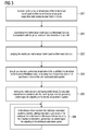
- Fig. 3 is a flow chart of the detailed method provided by an embodiment of the present invention, and as shown in Fig. 3 , the method mainly comprises the following steps:
- MC comprises: Membranes, Objects and Rules.
- a membrane is dynamic mapping of a specific environment, usually a specific FB is mapped.
- Object is the mapping of signals, parameters or messages transferred between FBs, and the states and disturbances of the distributed automation system in the present invention will both affect the objects of a membrane.
- Rules are the mapping of the cooperative relationships between the distributed entities, which can be divided into Local Rules and Global Rules.
- local rules describe different internal scanned states during the process of a task to be executed, i.e., the scanned state of each of the stages of a PLC program, and as shown in Fig. 4 , and particularly they comprise: Idle state 401, Input Scan state 402, Program Scan state 403 and Output Scan state 404.
- Each FB is in an Idle state 401 at the beginning; and when events or data start to be transferred into the FB, it is in Input Scan state 402; when the FB performs computation or event processing, it is in the Program Scan state 403; when the processing is completed and the results are outputted to an output cache, the FB is in the Output Scan state 404.
- Local Rules are inherent features of all the membranes in the MC model, i.e., they are universal rules, and they do not need to be adjusted or altered according to actual conditions.
- Global Rules that need to be adjusted or altered according to actual states are Global Rules, and the difference between Global Rules will affect the mathematical model based on MC. Since Global Rules are actually global constraint conditions of the FBs, they are usually called Global Constraint Rules. As provided in IEC 61499, Global Constraint Rules mainly comprise the constraint events as follows: Synchronization constraint, Transition constraint, Delay constraint, Loop Limit constraint and Dependence constraint.
- Synchronization constraint can be divided into: an event separating described as 1:n and an event merging described as n:1; Transition constraint can be divided into: a permissible event propagating described as 1:1, an event detaching described as 1:n and an event selecting described as n:1; Delay constraint is time delay between two events; Loop Limit constraint is the loop limit of an event; Dependence constraint is relevancy between two events, which can be divided into: Sequence constraint and Possible parallel constraint, for example: Sequence constraint described as E1 dep E2 E3 means: according to the sequence of event E1, event E2, event E3 or according to the sequence of event E1, event E3, event E2; and Possible parallel constraint described as E1 dep E2 E3 means: after the execution of event E1, event E2 and event E3 are executed synchronously.
- Determining the global constraint rules according to the cooperative relationships between the FBs in the controlled distributed automation system can be implemented through a user interface such as a GUI (Graphical User Interface), in which the cooperative relationships between the FBs can be restrained by using a preset universal FB, and the actual cooperative relationships between the FBs of the distributed automation system are used in the global constraint rules to establish the mathematical model based on the MC.
- GUI Graphic User Interface
- the distributed automation system shown in Fig. 5 is used to implement a wheel assembling link during automotive assembling, wherein an axle feeder 500 and a wheel feeder 510 are respectively used to send axle assembling material and wheel assembling material to a first transporting device 502 or a second transporting device 530 connected thereto.
- three automation assemblies i.e., a first mechanical device 540, a second mechanical device 550 and a third mechanical device 560 perform operations of material acquiring and assembling synchronously.
- the embodiment is described by taking the control of the assembling tasks of the first mechanical device 540, the second mechanical device 550 and the third mechanical device 560 as an example.
- the assembling task is divided into seven types in the form of "task: ⁇ operation>, ⁇ processing object>, ⁇ position>", and each of them can be mapped to a FB.
- FBs which are particularly FB_Start, FB_Fweld, FB_Rweld, FB_RL, FB_RR, FB_FL and FB_FR
- the cooperative relationships between these FBs can be: first performing FB_Start, then transporting to FB_Fweld and FB_Rweld which are performed synchronously, wherein FB_Fweld is further transported in the sequence of FB_FL and FB_FR, or in the sequence of FB_FR and FB_FL; and FB_Rweld is transported in the sequence of FB_RL and FB_RR, or of FB_RR and FB_RL.
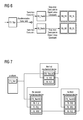
- a user can plan the global constraint rules of the model on GUI according to the cooperative relationships between the FBs as described above, as shown in Fig. 6 , the constraint between FB_start and FB_Fweld and the constraint between FB_Start and FB_Rweld are respectively the Transition constraints, the constraint between FB_Fweld and FB_Rweld is the Synchronization constraint, the constraint between FB_Fweld and FB_FL and constraint between FB_Fweld and FB_FR are the Sequence constraint in the Dependence constraint, and the constraint between FB_Rweld and FB_RR and the constraint between FB_Rweld and FB_RL are the Sequence constraint in the Dependence constraint.
- Step 302 the mathematical model based on MC is established according to the global constraint rules determined in step 301.
- each FB is mapped to a membrane, and the mathematical model based on MC is established using the global constraint rules determined above which represent the cooperative relationships between the FBs, the local rules in the mathematical model use the universal form, and the Objects use universal parameter form.
- Each FB has a corresponding description in the model, the description above is only an example of FB_Start, and the description of the other FBs will not be made redundantly here.
- Step 303 the established mathematical model based on MC is verified.
- the second level verification at simulation level.
- Simulation is a frequently used tool in the art of automation, which can be performed by operating a PLC unit in a virtual environment.
- the simulation test of a mathematical model based on MC can be performed using simulation tools, and if it can correctly run and achieve the expected results, verification is passed.
- This method of verification is capable of checking out inconspicuous errors in the mathematical model, to provide to the user an overall impression of controlling the distributed automation system by using the mathematical model, and to modify the mathematical model in time according to needs.
- the third level verification at criteria level. Verification at this level can be performed by LTL (Linear Temporal Logic), using a rewriting logics method to verify whether the established mathematical model based on MC achieves a preset criteria value, and here the criteria can be no deadlock, activity, correctness, etc.
- LTL Linear Temporal Logic
- Step 304 through a user interface, the instantiation of the established mathematical model based on MC is performed by using the executor corresponding to each FB in the distributed automation system.
- the user can determine the actual executor of each FB according to the structure of the controlled distributed automation system, i.e. the user can take the information of the executor corresponding to each FB in the distributed automation system as the instantiation parameter of each membrane.
- the platform corresponds to FB_Start, the first mechanical device 540 to FB_Fweld, FB_FL and FB_FR, the second mechanical device 550 to FB_Rweld, FB_RL, FB_RR and FB_FL, and the third mechanical device 560 to FB_Rweld, FB_RL, FB_RR and FB_FR.
- Table 1 executors instantiation parameters membranes platform FB_Start1 FB_Start the first mechanical device FB_Fweld1 FB_Fweld FB_FR1 FB_FR FB FL1 FB FL the second mechanical device FB Rweld2 FB Rweld FB FL2 FB FL FB RL2 FB RL FB RR2 FB RR the third mechanical device FB Rweld3 FB Rweld FB FR3 FB FR FB RR3 FB RR FB FB RL3 FB RL
- this step is to perform specific association between the mathematical model based on MC and the actually controlled distributed automation system, i.e., to map each entity of the distributed automation system to each membrane of the mathematical model, and to assign instantiation parameters to each membrane. Since the state of the distributed automation system is the original state at the beginning of control, there are no disturbance feedbacks, so the influence of disturbance is not taken into account in this step.
- Instantiation operation in this step can be inputted by the user via a user interface, and can also be performed by the user by calling instantiation parameters in an instance database via the user interface.
- Step 305 the mathematical model based on MC is rewritten after the instantiation according to a rewriting logics method, thus generating the control logics for outputting to the distributed automation system.
- the MC expression can be rewritten according to the rewriting logics method to obtain rewritten results, then the rewritten results are converted into the control logics, and the contents of this part are the prior art, which are not described redundantly here.
- Step 306 if disturbance information from the distributed automation system is received, the instantiation parameters of the mathematical model based on MC are altered using the disturbance information, and new control logics are generated for outputting to the distributed automation system.
- the distributed automation system is controlled continuously using the control logics generated in step 305 until the operation process of the distributed automation system is completed.
- control logics in the present invention are actually the control commands to the distributed automation system.
- the control logics generated after the execution of step 305 are shown in Fig. 7 ; if the distributed automation system feeds back the disturbance information of a malfunction of the second mechanical device, the instantiation parameters of membranes of the mathematical model after the instantiation will be altered according to the disturbance information, and in this example, after the malfunction of the second mechanical device has occurred, the instantiation parameter corresponding to FB_Rweld is only FB_Rweld3, without comprising FB_Rweld2, the instantiation parameter of FB_FL is only FB_FL1, without comprising FB_FL2, the instantiation parameter of FB_RL is only FB_RL3, without comprising FB_RL2, the instantiation parameter of FB_RR is only FB_RR3, without comprising FB_RR2, so the mathematical model is rewritten based on these altered instantiation parameters according to the rewriting logic method, and the generated new control logics are shown in Fig. 8 , where the first mechanical device and the third mechanical device cooperate to complete the assembling task
- the disturbances occurred may be the alteration of a portion of functions of some entities, for example, it may be the malfunction of a piling hole of the rear-left wheel at the second mechanical device, but other functions are normal, and in this case, only the corresponding instantiation parameter of FB_RL needs to be altered.
- Other disturbance information is also possible, and the disturbances will not be exhausted here.
- Fig. 9 is a structural diagram of the apparatus provided in an embodiment of the present invention, and as shown in Fig. 9 , the apparatus can comprise: a first user interface 901, a model establishing unit 902, a control logic generator unit 903, and a disturbance acquiring unit 904.
- the first user interface 901 acquires the cooperative relationships between the FBs in the distributed automation system as the global constraint rules, and provides the global constraint rules to the model establishing unit 902.
- the model establishing unit 902 establishes a mathematical model based on MC according to the global constraint rules.
- the control logic generator unit 903 generates the control logics according to the executor corresponding to each of the FBs in the distributed automation system, outputs them to the distributed automation system after the instantiation of the mathematical model based on MC, and alters the instantiation parameters of the mathematical model based on MC using the disturbance information provided by the disturbance acquiring unit 904, so as to generate the control logics for outputting to the distributed automation system.
- the disturbance acquiring unit 904 receives the disturbance information from the distributed automation system and provides the information to the control logic generator unit 903.
- the first user interface 901 mentioned above can provide a user interface such as GUI, and the user can determine the global constraint rules via the first user interface 901 according to the actual cooperative relationships between the FBs of the distributed automation system.
- the global constraint rules can comprise: a Synchronization constraint which comprises event splitting and event merging, a Transition constraint which comprises permissible event propagating, event detaching and event selecting, a Delay constraint, a Loop Limit constraint and a Dependence constraint which comprises a Sequence constraint and a Possible Parallel constraint.
- the model establishing unit 902 When the model establishing unit 902 establishes the mathematical model based on MC, it maps each FB in the distributed automation system to membranes of the mathematical model based on MC, and maps the cooperative relationships between the FBs inputted by the user to the global constraint rules of the mathematical model based on MC, and establishes the mathematical model based on MC.
- the apparatus can further comprise: a model verifying unit 905 for verifying at the Syntax Level, Simulation Level or Criteria Level the mathematical model based on MC generated by the model establishing unit 902; if the verification is passed, the control logic generator unit 903 is triggered to perform the operation of instantiation and establishing the control logics, and if the verification failed, the first user interface 901 is instructed to re-acquire the cooperative relationships between the FBs of the distributed automation system.
- a model verifying unit 905 for verifying at the Syntax Level, Simulation Level or Criteria Level the mathematical model based on MC generated by the model establishing unit 902; if the verification is passed, the control logic generator unit 903 is triggered to perform the operation of instantiation and establishing the control logics, and if the verification failed, the first user interface 901 is instructed to re-acquire the cooperative relationships between the FBs of the distributed automation system.
- the model verification unit 905 can display the relative information about verification failure to the user via the first user interface 901, and the user can re-input the global constraint rules through displayed information.
- verification levels increase in the order of syntax level verification, simulation level verification and criteria level verification; the user can select the verification level based on needs, and the model verification unit 905 can also display the verification process to the user via the first user interface 901, and let the user have a visual impression about the mathematical model based on MC.
- the control logic generator unit 903 described above can comprise particularly: an instantiating subunit 9031, a control logic generating subunit 9032 and a control logic outputting subunit 9033.
- the instantiating subunit 9031 performs the instantiation of the mathematical model based on MC according to the executor corresponding to each FB in the distributed automation system; and alters the instantiation parameters of the mathematical model based on MC using disturbance information provided by the disturbance acquiring unit 904.
- the control logic generating subunit 9032 rewrites the mathematical model based on MC according to the rewriting logics method, after the instantiation or the alteration of instantiation parameters to generate the control logics.
- the control logic outputting subunit 9033 outputs the control logics generated by the control logic generating subunit 9032 to the distributed automation system.
- the disturbance information acquired by the disturbance acquiring unit 904 may be changes of environment state of the distributed automation system, or changes of the state or parameters of the entities in the distributed automation system, and all such disturbance information can affect the instantiation parameters of each membrane of the mathematical model based on MC, which represents alteration of the executors of some FBs.
- the apparatus can further comprise: a second user interface 906 which acquires instantiation parameters inputted by the user according to the information of the executor corresponding to each FB in the distributed automation system, or the instantiation parameters called from an instantiation parameter database and provides them to the instantiating subunit 9031.
- a second user interface 906 which acquires instantiation parameters inputted by the user according to the information of the executor corresponding to each FB in the distributed automation system, or the instantiation parameters called from an instantiation parameter database and provides them to the instantiating subunit 9031.
- the instantiating subunit 9031 will assign the instantiation parameters to the corresponding membrane of each FB, so as to perform the instantiation of the mathematical model based on MC.
- the instantiating subunit 9031 can determine the FBs whose executor information has been altered according to the disturbance information provided by the disturbance acquiring unit 904, alter determined instantiation parameters of the corresponding membrane of the FB, and generate the control logics for outputting to the distributed automation system.
- the user can input the cooperative relationships between the FBs in the distributed automation system via the first user interface 901 as the global constraint rules
- the model establishing unit 902 maps each FB to the membranes and maps the cooperative relationships between the FBs to global constraint rules to establish the mathematical model based on MC.
- the mathematical model based on MC can be verified through the model verification unit 905, the way of verification can be the syntax level verification, the simulation level verification or the criteria level verification, and taking simulation level verification as an example, the mathematical model based on MC is operated in a virtual environment to validate whether such problems as deadlock and loop appear, and whether control output is correct, and simulation process and verification results can be displayed to the user via the first user interface 901. If verification fails, the user will be instructed to re-input the cooperative relationships between the FBs of the distributed automation system via the first user interface.
- the user can input instantiation parameters of the FBs via the second user interface 906 according to the executor corresponding to each FB in the distributed automation system, and provide these parameters to the control logic generator unit 903.
- the control logic generator unit performs instantiation of the mathematical model based on MC using the instantiation parameters inputted through the second user interface 906, rewrites the mathematical model after the instantiation according to the rewriting logic method, generates the control logics for outputting to the distributed automation system, and the distributed automation system performs corresponding operations according to the control logics.
- the distributed automation system is able to feed back disturbance information during operation, and the disturbance acquiring unit 904 provides such disturbance information to the control logic generator unit 903 after it acquires the disturbance information of the distributed automation system.
- the control logic generator unit 903 alters the instantiation parameters of the mathematical based on MC according to the disturbance information, rewrites the mathematical model based on MC after alteration of the instantiation parameters according to the rewriting logic method, and generates new control logics for outputting to the distributed automation system.
- new control logics are generated only by the control logic generator unit 903, without affecting the other units.
- the method and apparatus provided in the present invention determine the global constraint rules according to the cooperative relationships between the FBs in the distributed automation system, establish the mathematical model based on MC, and perform the instantiation of the mathematical model according to the executor corresponding to each FB, so as to generate control logics for outputting to the distributed automation system.
- the mathematical model After disturbances in the distributed automation system have occurred, the mathematical model will not be affected or altered, there is no need to write new codes manually, it is only necessary to automatically alter the instantiation parameters of the mathematical model based on MC by using the disturbance information to generate new control logics and outputting them to the distributed automation system without stopping the operation of the distributed control system, saving both time and manpower; moreover, when the mathematical model is established and the logics are generated using the method of the present invention, all the disturbances occurring affect the instantiation parameters of membranes, and the method for establishing new control logics using this feature can effectively deal with all the unpredictable disturbances and greatly improve the adaptability.
- the MC syntax used in the present invention is capable of simulating a dynamic system accurately, and dealing with the operating environment of the distributed automation system and disturbances during operation intelligently and flexibly.
- all the FBs in the present invention can be used for repackaging and use, i.e. for different distributed automation systems, the FBs can be combined flexibly so as to take the cooperative relationships as the global constraints to generate the mathematical model based on MC, and it is not necessary to alter the preset program, which has stronger flexibility.
Landscapes
- Engineering & Computer Science (AREA)
- Physics & Mathematics (AREA)
- Theoretical Computer Science (AREA)
- Chemical & Material Sciences (AREA)
- General Physics & Mathematics (AREA)
- Mathematical Physics (AREA)
- General Engineering & Computer Science (AREA)
- Nanotechnology (AREA)
- Automation & Control Theory (AREA)
- Life Sciences & Earth Sciences (AREA)
- Biophysics (AREA)
- Spectroscopy & Molecular Physics (AREA)
- Evolutionary Computation (AREA)
- Health & Medical Sciences (AREA)
- Artificial Intelligence (AREA)
- Biomedical Technology (AREA)
- Computational Linguistics (AREA)
- Data Mining & Analysis (AREA)
- Organic Chemistry (AREA)
- General Health & Medical Sciences (AREA)
- Molecular Biology (AREA)
- Computing Systems (AREA)
- Crystallography & Structural Chemistry (AREA)
- Software Systems (AREA)
- Manufacturing & Machinery (AREA)
- Quality & Reliability (AREA)
- Feedback Control In General (AREA)
Applications Claiming Priority (1)
| Application Number | Priority Date | Filing Date | Title |
|---|---|---|---|
| CN2009101311685A CN101859135B (zh) | 2009-04-07 | 2009-04-07 | 对分布式自动化系统进行控制的方法和装置 |
Publications (2)
| Publication Number | Publication Date |
|---|---|
| EP2239640A2 true EP2239640A2 (de) | 2010-10-13 |
| EP2239640A3 EP2239640A3 (de) | 2013-04-17 |
Family
ID=42289003
Family Applications (1)
| Application Number | Title | Priority Date | Filing Date |
|---|---|---|---|
| EP10158640.2A Withdrawn EP2239640A3 (de) | 2009-04-07 | 2010-03-31 | Verfahren und System zur Verwendung von Membranstein auf modelldynamische Koordinationslogik für automatische Systeme |
Country Status (3)
| Country | Link |
|---|---|
| US (1) | US8359111B2 (de) |
| EP (1) | EP2239640A3 (de) |
| CN (1) | CN101859135B (de) |
Families Citing this family (10)
| Publication number | Priority date | Publication date | Assignee | Title |
|---|---|---|---|---|
| CA2797234A1 (en) * | 2010-05-01 | 2011-11-10 | Core Technology Limited | Process execution components |
| CN102231133B (zh) * | 2011-07-05 | 2013-07-03 | 上海交通大学 | 基于重写逻辑的并发实时程序验证的优化处理系统及其方法 |
| US9094385B2 (en) | 2011-08-05 | 2015-07-28 | Battelle Memorial Institute | Intelligent sensor and controller framework for the power grid |
| US9846585B2 (en) * | 2013-05-14 | 2017-12-19 | Rockwell Automation Technologies, Inc. | System and method for emulation of an automation control system |
| EP3286611B1 (de) | 2015-04-21 | 2021-11-03 | Siemens Aktiengesellschaft | Verfahren und system für einen disziplinübergreifende datenvalidierungsprüfung in einem multidisziplinären engineering-system |
| CN109643093A (zh) * | 2016-08-30 | 2019-04-16 | 三菱电机株式会社 | 程序编辑装置、程序编辑方法及程序编辑程序 |
| CN107016206B (zh) * | 2017-04-17 | 2020-12-15 | 郑州铁路职业技术学院 | 一种用于自动控制系统的仿真的系统和方法 |
| DE102017223717B4 (de) * | 2017-12-22 | 2019-07-18 | Robert Bosch Gmbh | Verfahren zum Betreiben eines Roboters in einem Multiagentensystem, Roboter und Multiagentensystem |
| DE102018207539A1 (de) * | 2018-05-15 | 2019-11-21 | Robert Bosch Gmbh | Verfahren zum Betreiben eines Roboters in einem Multiagentensystem, Roboter und Multiagentensystem |
| CN110348132B (zh) * | 2019-07-15 | 2020-07-17 | 长光卫星技术有限公司 | 基于Bayes估计的轨控效果快速评估方法 |
Family Cites Families (9)
| Publication number | Priority date | Publication date | Assignee | Title |
|---|---|---|---|---|
| US4852018A (en) * | 1987-01-07 | 1989-07-25 | Trustees Of Boston University | Massively parellel real-time network architectures for robots capable of self-calibrating their operating parameters through associative learning |
| US5930154A (en) * | 1995-01-17 | 1999-07-27 | Intertech Ventures, Ltd. | Computer-based system and methods for information storage, modeling and simulation of complex systems organized in discrete compartments in time and space |
| US6341372B1 (en) * | 1997-05-01 | 2002-01-22 | William E. Datig | Universal machine translator of arbitrary languages |
| US6654729B1 (en) * | 1999-09-27 | 2003-11-25 | Science Applications International Corporation | Neuroelectric computational devices and networks |
| US20070094166A1 (en) * | 2002-08-05 | 2007-04-26 | Edwin Addison | Knowledge-based methods for genetic network analysis and the whole cell computer system based thereon |
| US7664723B2 (en) * | 2005-09-12 | 2010-02-16 | Microsoft Corporation | Symbolic computation using an inverted match |
| US20090124506A1 (en) * | 2007-11-02 | 2009-05-14 | Technion Research & Development Foundation Ltd. | Membrane computing |
| US8180617B1 (en) * | 2009-03-13 | 2012-05-15 | Klee Maurice M | Computer-based computational tools for use in electrophysiology |
| US20110004579A1 (en) * | 2008-03-14 | 2011-01-06 | Greg Snider | Neuromorphic Circuit |
-
2009
- 2009-04-07 CN CN2009101311685A patent/CN101859135B/zh not_active Expired - Fee Related
-
2010
- 2010-03-31 EP EP10158640.2A patent/EP2239640A3/de not_active Withdrawn
- 2010-04-07 US US12/755,543 patent/US8359111B2/en not_active Expired - Fee Related
Non-Patent Citations (1)
| Title |
|---|
| None |
Also Published As
| Publication number | Publication date |
|---|---|
| CN101859135B (zh) | 2012-07-18 |
| US20100280631A1 (en) | 2010-11-04 |
| US8359111B2 (en) | 2013-01-22 |
| CN101859135A (zh) | 2010-10-13 |
| EP2239640A3 (de) | 2013-04-17 |
Similar Documents
| Publication | Publication Date | Title |
|---|---|---|
| US8359111B2 (en) | Method and apparatus for controlling a distributed automation system | |
| US20200249663A1 (en) | Method and system for quick customized-design of intelligent workshop | |
| US9122269B2 (en) | Method and system for operating a machine from the field of automation engineering | |
| US10061670B2 (en) | Method and apparatus for automatically generating a component fault tree of a safety-critical system | |
| US20060294047A1 (en) | Method and apparatus for communicating transactions between an industrial controller and a programming interface | |
| CN104657274B (zh) | 软件界面测试方法及装置 | |
| US20190012168A1 (en) | Program generating apparatus | |
| CN107179971A (zh) | 用于can总线故障处理的自动编码方法和系统 | |
| CN101763072A (zh) | 数控加工代码的转换方法和装置 | |
| CN113157336A (zh) | 一种基于c#语言的抓具配置系统、方法、装置和存储介质 | |
| CN104907932A (zh) | 数控磨床系统中通过对话式参数实现加工程序处理的方法 | |
| US20150236901A1 (en) | Control system management apparatus | |
| CN111782493B (zh) | 用于mes的建模数据验证的建模辅助系统和方法 | |
| US20210216056A1 (en) | Programmable logic controller and operating method for a programmable logic controller and computer program product | |
| US20230237249A1 (en) | Method and system for generating an automation engineering project in a technical installation using multidisciplinary approach | |
| JP5374405B2 (ja) | モデルデバッグ装置およびモデルデバッグ方法 | |
| CN101515249B (zh) | 错误检查方法 | |
| JPH03241439A (ja) | テストデータ作成ツール | |
| CN115328501A (zh) | 一种模块化程序设计方法及系统 | |
| CN111680559B (zh) | 一种传感器信号名称快速同步方法、系统、装置及存储介质 | |
| CN115826506A (zh) | 水处理控制系统及控制装置 | |
| JP5379054B2 (ja) | 製造作業の検証環境システム、製造作業の検証方法および製造作業の検証プログラム | |
| CN106648648B (zh) | 基于Zookeeper的配置管理方法及系统 | |
| EP3575956B1 (de) | Verfahren und vorrichtung zur transformation der graphenkonfigurationssprache | |
| KR20050007856A (ko) | Nc가공 시뮬레이션을 통한 nc 가공데이터의 처리방법 |
Legal Events
| Date | Code | Title | Description |
|---|---|---|---|
| PUAI | Public reference made under article 153(3) epc to a published international application that has entered the european phase |
Free format text: ORIGINAL CODE: 0009012 |
|
| AK | Designated contracting states |
Kind code of ref document: A2 Designated state(s): AT BE BG CH CY CZ DE DK EE ES FI FR GB GR HR HU IE IS IT LI LT LU LV MC MK MT NL NO PL PT RO SE SI SK SM TR |
|
| AX | Request for extension of the european patent |
Extension state: AL BA ME RS |
|
| RAP1 | Party data changed (applicant data changed or rights of an application transferred) |
Owner name: SIEMENS AKTIENGESELLSCHAFT |
|
| PUAL | Search report despatched |
Free format text: ORIGINAL CODE: 0009013 |
|
| AK | Designated contracting states |
Kind code of ref document: A3 Designated state(s): AT BE BG CH CY CZ DE DK EE ES FI FR GB GR HR HU IE IS IT LI LT LU LV MC MK MT NL NO PL PT RO SE SI SK SM TR |
|
| AX | Request for extension of the european patent |
Extension state: AL BA ME RS |
|
| RIC1 | Information provided on ipc code assigned before grant |
Ipc: G05B 19/418 20060101AFI20130308BHEP Ipc: G05B 17/02 20060101ALI20130308BHEP |
|
| 17P | Request for examination filed |
Effective date: 20131014 |
|
| RBV | Designated contracting states (corrected) |
Designated state(s): AT BE BG CH CY CZ DE DK EE ES FI FR GB GR HR HU IE IS IT LI LT LU LV MC MK MT NL NO PL PT RO SE SI SK SM TR |
|
| 17Q | First examination report despatched |
Effective date: 20140513 |
|
| 17Q | First examination report despatched |
Effective date: 20140530 |
|
| RAP1 | Party data changed (applicant data changed or rights of an application transferred) |
Owner name: SIEMENS AKTIENGESELLSCHAFT |
|
| STAA | Information on the status of an ep patent application or granted ep patent |
Free format text: STATUS: THE APPLICATION IS DEEMED TO BE WITHDRAWN |
|
| 18D | Application deemed to be withdrawn |
Effective date: 20181002 |