EP2239181A2 - Einrichtung zur Steuerung einer Lenkung insbesondere eines Ketten- bzw. Gleiskettenfahrzeuges - Google Patents
Einrichtung zur Steuerung einer Lenkung insbesondere eines Ketten- bzw. Gleiskettenfahrzeuges Download PDFInfo
- Publication number
- EP2239181A2 EP2239181A2 EP20100003404 EP10003404A EP2239181A2 EP 2239181 A2 EP2239181 A2 EP 2239181A2 EP 20100003404 EP20100003404 EP 20100003404 EP 10003404 A EP10003404 A EP 10003404A EP 2239181 A2 EP2239181 A2 EP 2239181A2
- Authority
- EP
- European Patent Office
- Prior art keywords
- steering
- lever
- switching
- vehicle
- controlling
- Prior art date
- Legal status (The legal status is an assumption and is not a legal conclusion. Google has not performed a legal analysis and makes no representation as to the accuracy of the status listed.)
- Granted
Links
- 230000008878 coupling Effects 0.000 claims description 10
- 238000010168 coupling process Methods 0.000 claims description 10
- 238000005859 coupling reaction Methods 0.000 claims description 10
- 230000005540 biological transmission Effects 0.000 claims description 6
- 238000000034 method Methods 0.000 description 3
- 210000000078 claw Anatomy 0.000 description 2
- 230000002706 hydrostatic effect Effects 0.000 description 2
- 230000009347 mechanical transmission Effects 0.000 description 2
- 208000010201 Exanthema Diseases 0.000 description 1
- 230000000712 assembly Effects 0.000 description 1
- 238000000429 assembly Methods 0.000 description 1
- 230000006835 compression Effects 0.000 description 1
- 238000007906 compression Methods 0.000 description 1
- 230000001419 dependent effect Effects 0.000 description 1
- 201000005884 exanthem Diseases 0.000 description 1
- 230000010354 integration Effects 0.000 description 1
- 206010037844 rash Diseases 0.000 description 1
- 230000000717 retained effect Effects 0.000 description 1
Images



Classifications
-
- B—PERFORMING OPERATIONS; TRANSPORTING
- B62—LAND VEHICLES FOR TRAVELLING OTHERWISE THAN ON RAILS
- B62D—MOTOR VEHICLES; TRAILERS
- B62D11/00—Steering non-deflectable wheels; Steering endless tracks or the like
- B62D11/001—Steering non-deflectable wheels; Steering endless tracks or the like control systems
- B62D11/006—Mechanical control systems
-
- B—PERFORMING OPERATIONS; TRANSPORTING
- B62—LAND VEHICLES FOR TRAVELLING OTHERWISE THAN ON RAILS
- B62D—MOTOR VEHICLES; TRAILERS
- B62D11/00—Steering non-deflectable wheels; Steering endless tracks or the like
- B62D11/02—Steering non-deflectable wheels; Steering endless tracks or the like by differentially driving ground-engaging elements on opposite vehicle sides
- B62D11/06—Steering non-deflectable wheels; Steering endless tracks or the like by differentially driving ground-engaging elements on opposite vehicle sides by means of a single main power source
- B62D11/10—Steering non-deflectable wheels; Steering endless tracks or the like by differentially driving ground-engaging elements on opposite vehicle sides by means of a single main power source using gearings with differential power outputs on opposite sides, e.g. twin-differential or epicyclic gears
- B62D11/14—Steering non-deflectable wheels; Steering endless tracks or the like by differentially driving ground-engaging elements on opposite vehicle sides by means of a single main power source using gearings with differential power outputs on opposite sides, e.g. twin-differential or epicyclic gears differential power outputs being effected by additional power supply to one side, e.g. power originating from secondary power source
- B62D11/18—Steering non-deflectable wheels; Steering endless tracks or the like by differentially driving ground-engaging elements on opposite vehicle sides by means of a single main power source using gearings with differential power outputs on opposite sides, e.g. twin-differential or epicyclic gears differential power outputs being effected by additional power supply to one side, e.g. power originating from secondary power source the additional power supply being supplied hydraulically
- B62D11/183—Control systems therefor
Definitions
- the invention relates to the device for controlling a steering of a track or tracked vehicle, in particular the switching of a steering system for the forward or reverse driving of the tracked vehicle.
- the steering of tracked or caterpillar vehicles takes place by means of a hydrodynamic steering gear which is designed as part of the vehicle drive.
- this steering gear By means of this steering gear, the drive wheels of the (track) chains of each vehicle side are driven in accordance with the curve movement of the vehicle to be executed during forward and reverse travel.
- the steering gear is operated from the steering wheel via a shaft and an actuating linkage which acts on control valves of the transmission.
- a driving and steering actuator of a hydrostatic drive for a caterpillar describes the DE 15 05 677 C3 ,
- the inclusion of a pin and other connections ensures that the device requires relatively few parts and is thus less complicated and cheaper.
- DE 17 80 106 C3 discloses an adjusting device for the flow rate of a pump of the hydrostatic steering gear part of a superposition steering gear for caterpillars. This adjustment causes the reversal of the direction of travel and constant position de steering lever, the vehicle pivots about the same curve center point but in reverse rotation.
- Another device for controlling a steering for caterpillars the DE 29 48 214 A1 be removed.
- This includes a switching element which is rotatably connected to the steering column.
- a device for switching of steering gear especially for tracked vehicles also concerns the DE 38 19 446 C2 ,
- a steering wheel shaft is connected via at least one gear wheel with a control element for the steering gear having at least one toothing, so that the steering changeover can be formed without large pivoting spaces.
- the DE 42 10 728 A1 proposes a device for controlling a steering system for caterpillar vehicles, which comprises a lever which is rotatably connected to the steering wheel.
- the reversing lever is locked with a held at a distance from the pivot axis compression spring in the two positions.
- a device for steering direction reversal in tracked vehicles is also in the DE 196 06 793 C1 documented.
- the steering train is attached directly to an axially displaceable carriage, so that it is possible to dispense with a reversing lever, since the carriage is moved by a double-acting cylinder depending on the direction of travel in one of the two end positions.
- a mechanical device for Lenksinnumscrien is further with the DE 196 14 723 A1 published. This device is characterized by the fact that the steering geometry is retained after switching by means of an actuating cylinder in two operating positions of gas springs high force in the end positions.
- the DE 10 2005 030 495 A1 suggests, in turn, involve a Lenksinnumschalt issued between a steering and a steering gear and decouple the essential parts of this device of the steering movement itself completely. As a result, no components are adapted to the steering shaft, which would have to be moved in a steering rash.
- This Lenksinnumscnies is characterized in that it comprises a backdrop with a guide and a latching mechanism, wherein the guide is fixedly connected to a steering shaft of the steering wheel.
- the scenery acts together with an upper and a lower switching bearing a shift claw, wherein the shift claw is rotatable about a shift fulcrum. With this device the valid standards are better fulfilled.
- the invention has as its object to propose a further Lenksinnumscen in particular for an angular deflection, which meets the valid safety standards and has a structurally simple structure.
- the invention is based on the idea that the steering movement must be converted into a linear movement as an angular deflection, to integrate a so-called "switching of an articulation lever" in the mechanical transmission chain from the steering wheel to the vehicle transmission to a suitable location.
- the integration has been shown at an angle deflection of the steering linkage.
- the safety-relevant end position fixations of the switchable transmission elements for the steering operation are thereby secured in such a way that no forces caused by the steering force act directly on the actuator or actuators (eg hydraulic cylinders, spring elements) or they themselves are not continuously active or activated must, so that in case of failure of the switching elements outside the switching process itself this is safety-critical for their own steering movement.
- the components that provide for the switching also here completely decoupled from the steering movement, ie also that no components are adapted to the steering shaft, which would have to be moved with the steering deflection.
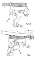
- Fig. 1 and 2 are marked with 20 parts of a Lenksinnumscrien (LSU), which is involved in the mechanical transmission path between a steering wheel and a vehicle transmission, in the present example in an angular deflection of the existing coupling rods of a caterpillar (assemblies not shown in detail, as known in the art).
- LSU Lenksinnumscrien
- the angle deflection 30 consists essentially of a pivoting or control housing 1, a pinion 3, a rack 4 and a first articulation lever 5 and a second articulation lever 8.
- the articulation lever 5 and the control housing 1 are rigidly interconnected.
- an associated ball 9 is incorporated, for example screwed, while another ball head 10 is connected to the lever 8.
- the coupling rods, not shown, terminate in coupling heads 9, 10.
- 11 is a switching element (eg hydraulic cylinder) of the vehicle, with 12 a further toothed rack guide.
- the rack 4 as a coupling between the shift gate 2 and switching element 11 is performed mechanically latching in the end positions and sensible in the end positions.
- the aforementioned parts are preferably supported by a common base plate 13 which is fixedly connected to the vehicle chassis.
- the LSU 20 consists of a shift gate 2, which is fixedly connected to the pinion 3, a control lever 6 and a pivot shaft 7, which are also supported by the base plate.
- the control lever 6 is connected via the pivot shaft 7 fixed to the lever 8 and controls its position depending on the forward or reverse drive.
- the coupling rods transmit the angular deflection of the steering wheel as a linear movement and terminate in the coupling heads 9, 10 of the LSU 20. If a linear movement of the coupling rods, so pivots the substructure (1, 5, 6, 7, 8, 9, 10 ) about the axis of rotation 14th
- Fig. 4 shows the LSU 20 in full steering "left” and Fig. 5 in full steering deflection "right” at the switch position "forward".
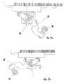
- the articulation lever 8 For the switching of the sense of steering for the "reversing" the articulation lever 8 has to be pivoted with the adapted ball head 10 on the opposite side of the rotation axis 14, so that the linear movement of the coupling rods inversely (in reverse) is performed ( Fig. 7a, b ).
- the switching element 11 is reversed, which rotates about the rack and pinion arrangement 3, 4, the shift gate 2.
- the cam of the shift gate 2 detects the control lever 6 adapted to the roller 15 and pivots the lever 8 by the corresponding angle in the opposite direction until it reaches the positive connection on the underside of the shift gate 2 ( Fig. 6 ag ).
- a failure of the hydraulic and / or electrical control is safety-critical for the switching mechanism, as this remains in the selected switching position. For example, if you want to switch in one of the aforementioned failures, the rack 4 can be decoupled from the switching element 11 by means of a mechanical coupling member and the whole thing can be switched manually (not shown in detail).
Landscapes
- Engineering & Computer Science (AREA)
- Automation & Control Theory (AREA)
- Chemical & Material Sciences (AREA)
- Combustion & Propulsion (AREA)
- Transportation (AREA)
- Mechanical Engineering (AREA)
- Arrangement Or Mounting Of Control Devices For Change-Speed Gearing (AREA)
- Non-Deflectable Wheels, Steering Of Trailers, Or Other Steering (AREA)
Abstract
Description
- Die Erfindung beschäftigt sich mit der Einrichtung zum Steuern einer Lenkung eines Gleisketten- bzw. Kettenfahrzeuges, insbesondere die Umschaltung einer Lenkung für das Vorwärts- oder Rückwärtsfahren des Kettenfahrzeuges.
- Das Lenken von Ketten- bzw. Gleiskettenfahrzeugen erfolgt durch ein hydrodynamisches Lenkgetriebe, das als Teil des Fahrzeugantriebs ausgebildet ist. Durch dieses Lenkgetriebe werden die Antriebsräder der (Gleis)- Ketten jeder Fahrzeugseite entsprechend der auszuführenden Kurvenbewegung des Fahrzeugs bei Vorwärts- und Rückwärtsfahrt angetrieben. Das Lenkgetriebe wird vom Lenkrad aus über eine Welle und ein Betätigungsgestänge, das auf Steuerventile des Getriebes einwirkt, betätigt.
- Bei Kettenfahrzeugen ist bekanntlich eine Lenksinnumkehr erforderlich, damit beim Vorwärts- und beim Rückwärtsfahren mit Einschlagen des Lenkrades beispielsweise nach rechts das Fahrzeug bei Fahrt eine Kurve nach rechts bzw. mit Einschlagen nach links eine Kurve nach links fährt. Ohne die Einrichtung zur Lenksinnumkehr würde bei einer Rückwärtsfahrt, wenn das Lenkrad nach rechts gedreht wird, das Fahrzeug eine Kurve nach rückwärts links fahren und umgekehrt. Eine ungleichsinnige Lenkradbewegung kann leicht zu einer Fehlbedienung und damit zu Unfällen führen.
- Eine Fahr- und Lenkbetätigungseinrichtung eines hydrostatischen Antriebs für ein Gleiskettenfahrzeug beschreibt die
DE 15 05 677 C3 . Durch die Einbindung eines Zapfens und weiterer Verbindungen wird erreicht, dass die Einrichtung verhältnismäßig wenige Teile benötigt und dadurch unkomplizierter und billiger wird. - Mit der
DE 17 80 106 C3 wird eine Einstellvorrichtung für den Förderstrom einer Pumpe des hydrostatischen Lenkgetriebeteils eines Überlagerungslenkgetriebes für Gleiskettenfahrzeuge offenbart. Diese Einstellvorrichtung bewirkt, dass bei Umkehr der Fahrtrichtung und gleichbleibender Stellung de Lenkhebels das Fahrzeug um den gleichen Kurvenmittelpunkt aber in umgekehrten Drehsinn schwenkt. - Eine weitere Vorrichtung zum Steuern einer Lenkung für Gleiskettenfahrzeuge kann der
DE 29 48 214 A1 entnommen werden. Diese umfasst ein Umschaltelement, das drehbar mit der Lenksäule verbunden ist. - Eine Vorrichtung zur Umschaltung von Lenkgetrieben insbesondere bei Kettenfahrzeugen betrifft auch die
DE 38 19 446 C2 . Hierbei ist eine Lenkradwelle über wenigstens ein Zahnrad mit einem wenigstens eine Verzahnung aufweisenden Steuerorgan für das Lenkgetriebe verbunden, sodass die Lenkumschaltung ohne große Schwenkräume ausgebildet werden kann. - Die
DE 42 10 728 A1 schlägt ihrerseits eine Vorrichtung zur Steuerung einer Lenkung für Gleiskettenfahrzeuge vor, die einen Umlenkhebel umfasst, der mit dem Lenkrad drehbar verbunden ist. Der Umlenkhebel wird dabei mit einer im Abstand zur Schwenkachse gehaltenen Druckfeder in den zwei Stellungen arretiert. - Eine Vorrichtung zur Lenksinnumkehr bei Kettenfahrzeugen ist zudem in der
DE 196 06 793 C1 dokumentiert. Dabei ist der Lenkungszug direkt an einem axial verschiebbaren Schlitten befestigt, sodass auf einen Umlenkhebel verzichtet werden kann, da der Schlitten von einem doppelt wirkenden Zylinder je nach Fahrtrichtungswahl in eine der beiden Endpositionen verschoben wird. - Eine mechanische Vorrichtung zur Lenksinnumschaltung wird des Weiteren mit der
DE 196 14 723 A1 publiziert. Diese Vorrichtung zeichnet sich dadurch aus, dass die Lenkgeometrie nach Umschaltung mittels eines Stellzylinders in zwei Betriebsstellungen von Gasfedern hoher Kraftwirkung in den Endlagen festgehalten wird. - Die
DE 10 2005 030 495 A1 schlägt ihrerseits vor, eine Lenksinnumschalteinrichtung zwischen einer Lenkung und einem Lenkgetriebe einzubinden und die wesentlichen Teile dieser Einrichtung von der Lenkbewegung selbst vollständig zu entkoppeln. Dadurch sind keine Komponenten an der Lenkwelle adaptiert, die bei einem Lenkausschlag mitbewegt werden müssten. Diese Lenksinnumschaltung zeichnet sich dadurch aus, dass sie eine Kulisse mit einer Führung und einem Rastmechanismus umfasst, wobei die Führung fest mit einer Lenkwelle des Lenkrades verbunden ist. Die Kulisse wirkt dabei mit einem oberen und einem unteren Schaltlager einer Schaltklaue zusammen, wobei die Schaltklaue um einen Schaltklauendrehpunkt verdrehbar ist. Mit dieser Einrichtung werden die gültigen Standards besser erfüllt. - Die Erfindung stellt sich die Aufgabe, eine weitere Lenksinnumschaltung insbesondere für eine Winkelumlenkung vorzuschlagen, die die gültigen Sicherheitsstandards erfüllt und einen konstruktiv einfachen Aufbau besitzt.
- Gelöst wird die Aufgabe durch die Merkmale des Patentanspruchs 1. Vorteilhafte Ausführungen sind den Unteransprüchen entnehmbar.
- Der Erfindung liegt die Idee zugrunde, da die Lenkbewegung als Winkelausschlag in eine lineare Bewegung umgewandelt werden muss, ein so genanntes "Schalten eines Anlenkhebels" in die mechanische Übertragungskette vom Lenkrad zum Fahrzeuggetriebe an eine geeignete Stelle einzubinden. Bevorzugt hat sich die Einbindung an einer Winkelumlenkung des Lenkgestänges gezeigt.
- Die für den Lenkbetrieb sicherheitsrelevanten Endlagenfixierungen der umschaltbaren Übertragungselemente werden dabei in der Art gesichert, dass keine durch die Lenkbewegung hervorgerufenen Kräfte direkt auf den bzw. die Stellglieder (z. B. Hydraulikzylinder, Federelemente) wirken oder aber diese selbst nicht stetig aktiv oder angesteuert werden müssen, sodass bei einem Ausfall der Schaltglieder außerhalb des Schaltvorganges selbst dies für die eigene Lenkbewegung sicherheitsunkritisch ist. Zudem sind die Komponenten, die für die Umschaltung sorgen, auch hier von der Lenkbewegung vollständig entkoppelt, d. h. auch, dass keine Komponenten an der Lenkwelle adaptiert sind, welche beim Lenkausschlag mitbewegt werden müssten.
- Anhand eines Ausführungsbeispiels mit Zeichnung soll die Erfindung näher erläutert werden.
- Es zeigt:
- Fig. 1
- eine perspektivische Darstellung einer kompletten Lenksinnumschaltung,
- Fig. 2
- die Lenksinnumschaltung aus
Fig. 1 in einer anderen Perspektive, - Fig. 3
- einen Schnitt durch die Hauptdrehachse,
- Fig. 4
- einen Lenkausschlag links,
- Fig. 5
- einen Lenkausschlag rechts,
- Fig. 6a -g
- einen Bewegungsablauf des Umschaltvorganges,
- Fig. 7a, b
- die beiden Endstellungen des Umschaltvorganges.
- In den
Fig. 1 und 2 sind mit 20 Teile einer Lenksinnumschaltung (LSU) gekennzeichnet, die in den mechanischen Übertragungsweg zwischen einem Lenkrad und einem Fahrzeuggetriebe eingebunden ist, im vorliegenden Beispiel in einer Winkelumlenkung der vorhandenen Koppelstangen eines Gleiskettenfahrzeugs (Baugruppen nicht näher dargestellt, da dem Fachmann bekannt). - Die Winkelumlenkung 30 besteht im Wesentlichen aus einem Schwenk- bzw. Steuergehäuse 1, einem Ritzel 3, einer Zahnstange 4 sowie einem ersten Anlenkhebel 5 und einem zweiten Anlenkhebel 8. Der Anlenkhebel 5 und das Steuergehäuse 1 sind starr miteinander verbunden. Im Anlenkhebel 5 ist ein zugehöriger Kugelkopf 9 eingebunden, beispielsweise eingeschraubt, während ein weiterer Kugelkopf 10 mit dem Anlenkhebel 8 verbunden ist. Die nicht näher dargestellten Koppelstangen enden in Koppelköpfen 9, 10. Mit 11 ist ein Schaltglied (z. B. Hydraulikzylinder) des Fahrzeugs gekennzeichnet, mit 12 eine weitere Zahnstangenführung. Die Zahnstange 4 als Kopplung zwischen Schaltkulisse 2 und Schaltglied 11 ist in den Endlagen mechanisch rastend ausgeführt und in den Endlagen sensierbar.
- Die vorgenannten Teile werden vorzugsweise von einer gemeinsamen Grundplatte 13 getragen, die ortsfest mit dem Fahrzeugchassis verbunden ist.
- Die Umsetzung der Winkelbewegung des Lenkrades in eine Linearbewegung für das Schaltglied 11 erfolgt über die Drehachse 14 der LSU 20.
- Die LSU 20 besteht aus einer Schaltkulisse 2, die mit dem Ritzel 3 fest verbunden ist, einem Steuerhebel 6 und einer Schwenkwelle 7, die ebenfalls von der Grundplatte getragen werden. Der Steuerhebel 6 ist über die Schwenkwelle 7 fest mit dem Anlenkhebel 8 verbunden und steuert dessen Position abhängig von der Vorwärts- oder Rückwärtsfahrt.
- Die nicht näher dargestellten Koppelstangen übertragen den Winkelausschlag des Lenkrades als lineare Bewegung und enden in den Koppelköpfen 9, 10 der LSU 20. Erfolgt eine lineare Bewegung der Koppelstangen, so schwenkt der Unterbau (1, 5, 6, 7, 8, 9, 10) um die Drehachse 14.
-
Fig. 4 zeigt die LSU 20 in vollem Lenkausschlag "Links" undFig. 5 in vollem Lenkausschlag "Rechts" bei der Schaltstellung "Vorwärts". - Für das Umschalten des Lenksinns für das "Rückwärtsfahren" muss der Anlenkhebel 8 mit dem adaptierten Kugelkopf 10 auf die gegenüberliegende Seite der Drehachse 14 geschwenkt werden, sodass die lineare Bewegung der Koppelstangen invers (umgekehrt) ausgeführt wird (
Fig. 7a, b ). - Dafür wird das Schaltglied 11 umgesteuert, welches über die Zahnstangen-Ritzel Anordnung 3, 4 die Schaltkulisse 2 dreht. Die Steuerkurve der Schaltkulisse 2 erfasst die am Steuerhebel 6 adaptierte Laufrolle 15 und schwenkt den Anlenkhebel 8 um den entsprechenden Winkel in die entgegengesetzte Richtung bis dieser den Formschluss an der Unterseite der Schaltkulisse 2 erreicht (
Fig. 6 a-g ). - Für das Umschalten des Lenksinns für das "Vorwärtsfahren" sind die Abläufe aus den
Fig. 6 a-g in umgekehrter Reihenfolge zu sehen. - Ein Ausfall der Hydraulik und / oder der elektrischen Ansteuerung ist für die Umschaltmechanik sicherheitsunkritisch, da diese in der angewählten Schaltstellung verharrt. Soll beispielsweise bei einem der vorgenannten Ausfällen umgeschaltet werden, kann die Zahnstange 4 mittels eines mechanischen Kupplungsgliedes vom Schaltglied 11 entkoppelt und das Ganze manuell umgeschaltet werden (nicht näher dargestellt).
Claims (4)
- Einrichtung zur Steuerung einer Lenkung insbesondere eines Ketten- bzw. Gleiskettenfahrzeuges, wobei eine Lenksinn-Umschaltung (20) zwischen einem Lenkrad oder dergleichen zur Steuerung des Fahrzeugs und einem Fahrzeuggetriebe, vorzugsweise in einer Winkelumlenkung (30), bestehend im Wesentlichen aus einem Schwenk- bzw. Steuergehäuse (1), einem Ritzel (3), einer Zahnstange (4) sowie einem ersten Anlenkhebel (5) und einem zweiten Anlenkhebel (8), eingebunden ist, dadurch gekennzeichnet, dass die Lenksinn-Umschalteinrichtung (20) im Wesentlichen besteht aus einer Schaltkulisse (2), einem Steuerhebel (6) sowie einer Schwenkwelle (7), wobei der Steuerhebel (6) über die Schwenkwelle (7) fest mit dem Anlenkhebel (8) verbunden ist und dessen Position abhängig von der Vorwärts- oder Rückwärtsfahrt steuert.
- Einrichtung nach Anspruch 1, dadurch gekennzeichnet, dass der Anlenkhebel (5) und das Steuergehäuse (1) und die Schaltkulisse (2) mit dem Ritzel (3) starr miteinander verbunden sind, im Anlenkhebel (5) ein zugehöriger Kugelkopf (9) eingebunden während ein weiterer Kugelkopf (10) mit dem Anlenkhebel (8) verbunden ist und die Zahnstange (4) als Kopplung zwischen Schaltkulisse (2) und Schaltglied (11) dient.
- Einrichtung nach Anspruch 1 oder 2, dadurch gekennzeichnet, dass Teile des Fahrzeuggetriebes und die Lenksinn- Umschaltung (20) von einer Grundplatte (13) getragen ortsfest mit dem Fahrzeugchassis verbunden ist.
- Einrichtung nach einem der Ansprüche 1 bis 3, dadurch gekennzeichnet, dass das Schaltglied (11) ein Hydraulikzylinder ist.
Applications Claiming Priority (1)
| Application Number | Priority Date | Filing Date | Title |
|---|---|---|---|
| DE102009016323A DE102009016323A1 (de) | 2009-04-06 | 2009-04-06 | Einrichtung zur Steuerung einer Lenkung insbesondere eines Ketten- bzw. Gleiskettenfahrzeuges |
Publications (3)
| Publication Number | Publication Date |
|---|---|
| EP2239181A2 true EP2239181A2 (de) | 2010-10-13 |
| EP2239181A3 EP2239181A3 (de) | 2014-09-03 |
| EP2239181B1 EP2239181B1 (de) | 2015-08-26 |
Family
ID=42167650
Family Applications (1)
| Application Number | Title | Priority Date | Filing Date |
|---|---|---|---|
| EP10003404.0A Not-in-force EP2239181B1 (de) | 2009-04-06 | 2010-03-30 | Einrichtung zur Steuerung einer Lenkung insbesondere eines Ketten- bzw. Gleiskettenfahrzeuges |
Country Status (3)
| Country | Link |
|---|---|
| EP (1) | EP2239181B1 (de) |
| DE (1) | DE102009016323A1 (de) |
| ES (1) | ES2550080T3 (de) |
Citations (8)
| Publication number | Priority date | Publication date | Assignee | Title |
|---|---|---|---|---|
| DE1780106A1 (de) | 1968-08-01 | 1971-12-30 | Zahnradfabrik Friedrichshafen | Einrichtung zur Umsteuerung der Abtriebsdrehrichtung eines hydrostatischen Motors |
| DE1505677C3 (de) | 1966-12-03 | 1975-04-03 | Robert Bosch Gmbh, 7000 Stuttgart | Fahr- und Lenkbetätigungseinrlchtung des hydrostatischen Antriebs für ein Fahrzeug, insbesondere für ein Gleiskettenfahrzeug |
| DE2948214A1 (de) | 1979-11-30 | 1981-06-04 | Dr.Ing.H.C. F. Porsche Ag, 7000 Stuttgart | Vorrichtung zum steuern einer lenkung fuer gleiskettenfahrzeuge |
| DE3819446C2 (de) | 1988-06-08 | 1992-04-23 | Mak System Gmbh, 2300 Kiel, De | |
| DE4210728A1 (de) | 1992-04-01 | 1993-10-07 | Porsche Ag | Vorrichtung zum Steuern einer Lenkung für Gleiskettenfahrzeuge |
| DE19606793C1 (de) | 1996-02-23 | 1997-04-10 | Mak System Gmbh | Vorrichtung zur Lenksinnumkehr bei Kettenfahrzeugen |
| DE19614723A1 (de) | 1996-04-15 | 1997-11-06 | Mak System Gmbh | Vorrichtung zum Ansteuern einer Lenkung von Fahrzeugen |
| DE102005030495A1 (de) | 2005-06-30 | 2007-01-04 | Rheinmetall Landsysteme Gmbh | Einrichtung zum Steuern einer Lenkung insbesondere für Gleis- und Kettenfahrzeuge |
-
2009
- 2009-04-06 DE DE102009016323A patent/DE102009016323A1/de not_active Withdrawn
-
2010
- 2010-03-30 ES ES10003404.0T patent/ES2550080T3/es active Active
- 2010-03-30 EP EP10003404.0A patent/EP2239181B1/de not_active Not-in-force
Patent Citations (8)
| Publication number | Priority date | Publication date | Assignee | Title |
|---|---|---|---|---|
| DE1505677C3 (de) | 1966-12-03 | 1975-04-03 | Robert Bosch Gmbh, 7000 Stuttgart | Fahr- und Lenkbetätigungseinrlchtung des hydrostatischen Antriebs für ein Fahrzeug, insbesondere für ein Gleiskettenfahrzeug |
| DE1780106A1 (de) | 1968-08-01 | 1971-12-30 | Zahnradfabrik Friedrichshafen | Einrichtung zur Umsteuerung der Abtriebsdrehrichtung eines hydrostatischen Motors |
| DE2948214A1 (de) | 1979-11-30 | 1981-06-04 | Dr.Ing.H.C. F. Porsche Ag, 7000 Stuttgart | Vorrichtung zum steuern einer lenkung fuer gleiskettenfahrzeuge |
| DE3819446C2 (de) | 1988-06-08 | 1992-04-23 | Mak System Gmbh, 2300 Kiel, De | |
| DE4210728A1 (de) | 1992-04-01 | 1993-10-07 | Porsche Ag | Vorrichtung zum Steuern einer Lenkung für Gleiskettenfahrzeuge |
| DE19606793C1 (de) | 1996-02-23 | 1997-04-10 | Mak System Gmbh | Vorrichtung zur Lenksinnumkehr bei Kettenfahrzeugen |
| DE19614723A1 (de) | 1996-04-15 | 1997-11-06 | Mak System Gmbh | Vorrichtung zum Ansteuern einer Lenkung von Fahrzeugen |
| DE102005030495A1 (de) | 2005-06-30 | 2007-01-04 | Rheinmetall Landsysteme Gmbh | Einrichtung zum Steuern einer Lenkung insbesondere für Gleis- und Kettenfahrzeuge |
Also Published As
| Publication number | Publication date |
|---|---|
| DE102009016323A1 (de) | 2010-10-14 |
| EP2239181B1 (de) | 2015-08-26 |
| ES2550080T3 (es) | 2015-11-04 |
| EP2239181A3 (de) | 2014-09-03 |
Similar Documents
| Publication | Publication Date | Title |
|---|---|---|
| EP3036147B1 (de) | Lenkanschlag | |
| EP1984656B1 (de) | Schaltvorrichtung für kraftfahrzeug-wechselgetriebe | |
| EP2497658A1 (de) | Zugfahrzeug mit Fahrzeuganhänger | |
| EP0143861B1 (de) | Fahrzeug mit lenkbaren Rädern | |
| CH644555A5 (en) | Device for controlling the swivelling movement of a wheel set of a rail vehicle in a bend | |
| DE29822472U1 (de) | Hydraulikanlage für die Dämpfung der Drehbewegung eines Drehgelenkes zwischen zwei Fahrzeugteilen eines Gelenkfahrzeuges, z.B. eines Gelenkbusses | |
| EP2920105B1 (de) | Lenksystem für ein flurförderzeug | |
| DE69635839T2 (de) | Ansteuervorrichtung für arbeitsfahrzeug | |
| EP0207260A2 (de) | Einhebelbedienung für ein Schaltgetriebe eines Gleiskettenfahrzeuges | |
| EP2239181B1 (de) | Einrichtung zur Steuerung einer Lenkung insbesondere eines Ketten- bzw. Gleiskettenfahrzeuges | |
| DE10353240A1 (de) | Schalteinrichtung | |
| DE2948214C2 (de) | ||
| EP1996444B1 (de) | Vorrichtung zum umschalten des lenkgetriebes eines kettenfahrzeuges | |
| DE2055364C3 (de) | Schaltgetriebe für die Lenkung von Fahrzeugrädern, insbesondere von Kraftfahrzeugen mit Mehrachslenkung | |
| DE10046168A1 (de) | Lenksystem | |
| DE947047C (de) | Hilfskraft-Lenkeinrichtung, insbesondere fuer Kraftfahrzeuge | |
| DE2140611B2 (de) | Schalt- und Lenk-Bremsbetätigungsvorrichtung, insbesondere für Kraftfahrzeuge mit nicht schwenkbaren Rädern bzw. Gleisketten | |
| DE102005030495B4 (de) | Einrichtung zum Steuern einer Lenkung eines Gleiskettenfahrzeuges | |
| DE19614723C2 (de) | Vorrichtung zum Ansteuern einer Lenkung von Fahrzeugen | |
| EP2222531A1 (de) | Servoventil für eine hydraulische servolenkung | |
| DE102022114732B4 (de) | Auslenkvorrichtung | |
| EP1604884B1 (de) | Einrichtung zur Umkehrung der Lenkbewegung einer Lenkradwelle | |
| DE3905818C2 (de) | Hinterrad-Lenkvorrichtung für Kraftfahrzeuge | |
| DE4210728A1 (de) | Vorrichtung zum Steuern einer Lenkung für Gleiskettenfahrzeuge | |
| DE10048697A1 (de) | Steer-by-Wire-Lenkanlage mit Zahnstangen-Hydrolenksteller |
Legal Events
| Date | Code | Title | Description |
|---|---|---|---|
| PUAI | Public reference made under article 153(3) epc to a published international application that has entered the european phase |
Free format text: ORIGINAL CODE: 0009012 |
|
| AK | Designated contracting states |
Kind code of ref document: A2 Designated state(s): AT BE BG CH CY CZ DE DK EE ES FI FR GB GR HR HU IE IS IT LI LT LU LV MC MK MT NL NO PL PT RO SE SI SK SM TR |
|
| AX | Request for extension of the european patent |
Extension state: AL BA ME RS |
|
| RAP1 | Party data changed (applicant data changed or rights of an application transferred) |
Owner name: RHEINMETALL LANDSYSTEME GMBH |
|
| PUAL | Search report despatched |
Free format text: ORIGINAL CODE: 0009013 |
|
| AK | Designated contracting states |
Kind code of ref document: A3 Designated state(s): AT BE BG CH CY CZ DE DK EE ES FI FR GB GR HR HU IE IS IT LI LT LU LV MC MK MT NL NO PL PT RO SE SI SK SM TR |
|
| AX | Request for extension of the european patent |
Extension state: AL BA ME RS |
|
| RIC1 | Information provided on ipc code assigned before grant |
Ipc: B62D 11/00 20060101AFI20140730BHEP |
|
| 17P | Request for examination filed |
Effective date: 20141021 |
|
| RBV | Designated contracting states (corrected) |
Designated state(s): AT BE BG CH CY CZ DE DK EE ES FI FR GB GR HR HU IE IS IT LI LT LU LV MC MK MT NL NO PL PT RO SE SI SK SM TR |
|
| GRAP | Despatch of communication of intention to grant a patent |
Free format text: ORIGINAL CODE: EPIDOSNIGR1 |
|
| INTG | Intention to grant announced |
Effective date: 20150212 |
|
| RIC1 | Information provided on ipc code assigned before grant |
Ipc: B62D 11/00 20060101AFI20150130BHEP Ipc: B62D 11/18 20060101ALI20150130BHEP |
|
| GRAP | Despatch of communication of intention to grant a patent |
Free format text: ORIGINAL CODE: EPIDOSNIGR1 |
|
| INTG | Intention to grant announced |
Effective date: 20150317 |
|
| GRAS | Grant fee paid |
Free format text: ORIGINAL CODE: EPIDOSNIGR3 |
|
| GRAA | (expected) grant |
Free format text: ORIGINAL CODE: 0009210 |
|
| AK | Designated contracting states |
Kind code of ref document: B1 Designated state(s): AT BE BG CH CY CZ DE DK EE ES FI FR GB GR HR HU IE IS IT LI LT LU LV MC MK MT NL NO PL PT RO SE SI SK SM TR |
|
| REG | Reference to a national code |
Ref country code: GB Ref legal event code: FG4D Free format text: NOT ENGLISH |
|
| REG | Reference to a national code |
Ref country code: CH Ref legal event code: EP |
|
| REG | Reference to a national code |
Ref country code: AT Ref legal event code: REF Ref document number: 745002 Country of ref document: AT Kind code of ref document: T Effective date: 20150915 |
|
| REG | Reference to a national code |
Ref country code: IE Ref legal event code: FG4D Free format text: LANGUAGE OF EP DOCUMENT: GERMAN |
|
| REG | Reference to a national code |
Ref country code: DE Ref legal event code: R096 Ref document number: 502010010128 Country of ref document: DE |
|
| REG | Reference to a national code |
Ref country code: ES Ref legal event code: FG2A Ref document number: 2550080 Country of ref document: ES Kind code of ref document: T3 Effective date: 20151104 |
|
| REG | Reference to a national code |
Ref country code: LT Ref legal event code: MG4D |
|
| PG25 | Lapsed in a contracting state [announced via postgrant information from national office to epo] |
Ref country code: NO Free format text: LAPSE BECAUSE OF FAILURE TO SUBMIT A TRANSLATION OF THE DESCRIPTION OR TO PAY THE FEE WITHIN THE PRESCRIBED TIME-LIMIT Effective date: 20151126 Ref country code: GR Free format text: LAPSE BECAUSE OF FAILURE TO SUBMIT A TRANSLATION OF THE DESCRIPTION OR TO PAY THE FEE WITHIN THE PRESCRIBED TIME-LIMIT Effective date: 20151127 Ref country code: LT Free format text: LAPSE BECAUSE OF FAILURE TO SUBMIT A TRANSLATION OF THE DESCRIPTION OR TO PAY THE FEE WITHIN THE PRESCRIBED TIME-LIMIT Effective date: 20150826 Ref country code: LV Free format text: LAPSE BECAUSE OF FAILURE TO SUBMIT A TRANSLATION OF THE DESCRIPTION OR TO PAY THE FEE WITHIN THE PRESCRIBED TIME-LIMIT Effective date: 20150826 Ref country code: FI Free format text: LAPSE BECAUSE OF FAILURE TO SUBMIT A TRANSLATION OF THE DESCRIPTION OR TO PAY THE FEE WITHIN THE PRESCRIBED TIME-LIMIT Effective date: 20150826 |
|
| REG | Reference to a national code |
Ref country code: NL Ref legal event code: MP Effective date: 20150826 |
|
| PG25 | Lapsed in a contracting state [announced via postgrant information from national office to epo] |
Ref country code: SE Free format text: LAPSE BECAUSE OF FAILURE TO SUBMIT A TRANSLATION OF THE DESCRIPTION OR TO PAY THE FEE WITHIN THE PRESCRIBED TIME-LIMIT Effective date: 20150826 Ref country code: IS Free format text: LAPSE BECAUSE OF FAILURE TO SUBMIT A TRANSLATION OF THE DESCRIPTION OR TO PAY THE FEE WITHIN THE PRESCRIBED TIME-LIMIT Effective date: 20151226 Ref country code: PL Free format text: LAPSE BECAUSE OF FAILURE TO SUBMIT A TRANSLATION OF THE DESCRIPTION OR TO PAY THE FEE WITHIN THE PRESCRIBED TIME-LIMIT Effective date: 20150826 Ref country code: HR Free format text: LAPSE BECAUSE OF FAILURE TO SUBMIT A TRANSLATION OF THE DESCRIPTION OR TO PAY THE FEE WITHIN THE PRESCRIBED TIME-LIMIT Effective date: 20150826 Ref country code: PT Free format text: LAPSE BECAUSE OF FAILURE TO SUBMIT A TRANSLATION OF THE DESCRIPTION OR TO PAY THE FEE WITHIN THE PRESCRIBED TIME-LIMIT Effective date: 20151228 |
|
| REG | Reference to a national code |
Ref country code: FR Ref legal event code: PLFP Year of fee payment: 7 |
|
| PG25 | Lapsed in a contracting state [announced via postgrant information from national office to epo] |
Ref country code: NL Free format text: LAPSE BECAUSE OF FAILURE TO SUBMIT A TRANSLATION OF THE DESCRIPTION OR TO PAY THE FEE WITHIN THE PRESCRIBED TIME-LIMIT Effective date: 20150826 |
|
| PG25 | Lapsed in a contracting state [announced via postgrant information from national office to epo] |
Ref country code: EE Free format text: LAPSE BECAUSE OF FAILURE TO SUBMIT A TRANSLATION OF THE DESCRIPTION OR TO PAY THE FEE WITHIN THE PRESCRIBED TIME-LIMIT Effective date: 20150826 Ref country code: SK Free format text: LAPSE BECAUSE OF FAILURE TO SUBMIT A TRANSLATION OF THE DESCRIPTION OR TO PAY THE FEE WITHIN THE PRESCRIBED TIME-LIMIT Effective date: 20150826 Ref country code: CZ Free format text: LAPSE BECAUSE OF FAILURE TO SUBMIT A TRANSLATION OF THE DESCRIPTION OR TO PAY THE FEE WITHIN THE PRESCRIBED TIME-LIMIT Effective date: 20150826 Ref country code: DK Free format text: LAPSE BECAUSE OF FAILURE TO SUBMIT A TRANSLATION OF THE DESCRIPTION OR TO PAY THE FEE WITHIN THE PRESCRIBED TIME-LIMIT Effective date: 20150826 Ref country code: IT Free format text: LAPSE BECAUSE OF FAILURE TO SUBMIT A TRANSLATION OF THE DESCRIPTION OR TO PAY THE FEE WITHIN THE PRESCRIBED TIME-LIMIT Effective date: 20150826 |
|
| REG | Reference to a national code |
Ref country code: DE Ref legal event code: R097 Ref document number: 502010010128 Country of ref document: DE |
|
| PG25 | Lapsed in a contracting state [announced via postgrant information from national office to epo] |
Ref country code: RO Free format text: LAPSE BECAUSE OF FAILURE TO SUBMIT A TRANSLATION OF THE DESCRIPTION OR TO PAY THE FEE WITHIN THE PRESCRIBED TIME-LIMIT Effective date: 20150826 |
|
| PLBE | No opposition filed within time limit |
Free format text: ORIGINAL CODE: 0009261 |
|
| STAA | Information on the status of an ep patent application or granted ep patent |
Free format text: STATUS: NO OPPOSITION FILED WITHIN TIME LIMIT |
|
| 26N | No opposition filed |
Effective date: 20160530 |
|
| PG25 | Lapsed in a contracting state [announced via postgrant information from national office to epo] |
Ref country code: SI Free format text: LAPSE BECAUSE OF FAILURE TO SUBMIT A TRANSLATION OF THE DESCRIPTION OR TO PAY THE FEE WITHIN THE PRESCRIBED TIME-LIMIT Effective date: 20150826 Ref country code: BE Free format text: LAPSE BECAUSE OF NON-PAYMENT OF DUE FEES Effective date: 20160331 |
|
| PG25 | Lapsed in a contracting state [announced via postgrant information from national office to epo] |
Ref country code: MC Free format text: LAPSE BECAUSE OF FAILURE TO SUBMIT A TRANSLATION OF THE DESCRIPTION OR TO PAY THE FEE WITHIN THE PRESCRIBED TIME-LIMIT Effective date: 20150826 Ref country code: LU Free format text: LAPSE BECAUSE OF FAILURE TO SUBMIT A TRANSLATION OF THE DESCRIPTION OR TO PAY THE FEE WITHIN THE PRESCRIBED TIME-LIMIT Effective date: 20160330 |
|
| REG | Reference to a national code |
Ref country code: CH Ref legal event code: PL |
|
| GBPC | Gb: european patent ceased through non-payment of renewal fee |
Effective date: 20160330 |
|
| REG | Reference to a national code |
Ref country code: IE Ref legal event code: MM4A |
|
| PG25 | Lapsed in a contracting state [announced via postgrant information from national office to epo] |
Ref country code: IE Free format text: LAPSE BECAUSE OF NON-PAYMENT OF DUE FEES Effective date: 20160330 Ref country code: GB Free format text: LAPSE BECAUSE OF NON-PAYMENT OF DUE FEES Effective date: 20160330 Ref country code: LI Free format text: LAPSE BECAUSE OF NON-PAYMENT OF DUE FEES Effective date: 20160331 Ref country code: CH Free format text: LAPSE BECAUSE OF NON-PAYMENT OF DUE FEES Effective date: 20160331 |
|
| REG | Reference to a national code |
Ref country code: FR Ref legal event code: PLFP Year of fee payment: 8 |
|
| REG | Reference to a national code |
Ref country code: AT Ref legal event code: MM01 Ref document number: 745002 Country of ref document: AT Kind code of ref document: T Effective date: 20160330 |
|
| PG25 | Lapsed in a contracting state [announced via postgrant information from national office to epo] |
Ref country code: MT Free format text: LAPSE BECAUSE OF FAILURE TO SUBMIT A TRANSLATION OF THE DESCRIPTION OR TO PAY THE FEE WITHIN THE PRESCRIBED TIME-LIMIT Effective date: 20150826 Ref country code: AT Free format text: LAPSE BECAUSE OF NON-PAYMENT OF DUE FEES Effective date: 20160330 |
|
| REG | Reference to a national code |
Ref country code: FR Ref legal event code: PLFP Year of fee payment: 9 |
|
| PG25 | Lapsed in a contracting state [announced via postgrant information from national office to epo] |
Ref country code: SM Free format text: LAPSE BECAUSE OF FAILURE TO SUBMIT A TRANSLATION OF THE DESCRIPTION OR TO PAY THE FEE WITHIN THE PRESCRIBED TIME-LIMIT Effective date: 20150826 Ref country code: CY Free format text: LAPSE BECAUSE OF FAILURE TO SUBMIT A TRANSLATION OF THE DESCRIPTION OR TO PAY THE FEE WITHIN THE PRESCRIBED TIME-LIMIT Effective date: 20150826 Ref country code: HU Free format text: LAPSE BECAUSE OF FAILURE TO SUBMIT A TRANSLATION OF THE DESCRIPTION OR TO PAY THE FEE WITHIN THE PRESCRIBED TIME-LIMIT; INVALID AB INITIO Effective date: 20100330 |
|
| PG25 | Lapsed in a contracting state [announced via postgrant information from national office to epo] |
Ref country code: MK Free format text: LAPSE BECAUSE OF FAILURE TO SUBMIT A TRANSLATION OF THE DESCRIPTION OR TO PAY THE FEE WITHIN THE PRESCRIBED TIME-LIMIT Effective date: 20150826 |
|
| PG25 | Lapsed in a contracting state [announced via postgrant information from national office to epo] |
Ref country code: BG Free format text: LAPSE BECAUSE OF FAILURE TO SUBMIT A TRANSLATION OF THE DESCRIPTION OR TO PAY THE FEE WITHIN THE PRESCRIBED TIME-LIMIT Effective date: 20150826 |
|
| PGFP | Annual fee paid to national office [announced via postgrant information from national office to epo] |
Ref country code: FR Payment date: 20190322 Year of fee payment: 10 Ref country code: DE Payment date: 20190321 Year of fee payment: 10 |
|
| PGFP | Annual fee paid to national office [announced via postgrant information from national office to epo] |
Ref country code: TR Payment date: 20190320 Year of fee payment: 10 |
|
| PGFP | Annual fee paid to national office [announced via postgrant information from national office to epo] |
Ref country code: ES Payment date: 20190418 Year of fee payment: 10 |
|
| REG | Reference to a national code |
Ref country code: DE Ref legal event code: R119 Ref document number: 502010010128 Country of ref document: DE |
|
| PG25 | Lapsed in a contracting state [announced via postgrant information from national office to epo] |
Ref country code: DE Free format text: LAPSE BECAUSE OF NON-PAYMENT OF DUE FEES Effective date: 20201001 Ref country code: FR Free format text: LAPSE BECAUSE OF NON-PAYMENT OF DUE FEES Effective date: 20200331 |
|
| REG | Reference to a national code |
Ref country code: ES Ref legal event code: FD2A Effective date: 20210811 |
|
| PG25 | Lapsed in a contracting state [announced via postgrant information from national office to epo] |
Ref country code: ES Free format text: LAPSE BECAUSE OF NON-PAYMENT OF DUE FEES Effective date: 20200331 |
|
| PG25 | Lapsed in a contracting state [announced via postgrant information from national office to epo] |
Ref country code: TR Free format text: LAPSE BECAUSE OF NON-PAYMENT OF DUE FEES Effective date: 20200330 |