EP2238773B1 - Appareil auditif à paroi constituée d'une carte à circuit imprimé - Google Patents
Appareil auditif à paroi constituée d'une carte à circuit imprimé Download PDFInfo
- Publication number
- EP2238773B1 EP2238773B1 EP08869117.5A EP08869117A EP2238773B1 EP 2238773 B1 EP2238773 B1 EP 2238773B1 EP 08869117 A EP08869117 A EP 08869117A EP 2238773 B1 EP2238773 B1 EP 2238773B1
- Authority
- EP
- European Patent Office
- Prior art keywords
- housing
- hearing instrument
- elongate member
- ear canal
- hearing
- Prior art date
- Legal status (The legal status is an assumption and is not a legal conclusion. Google has not performed a legal analysis and makes no representation as to the accuracy of the status listed.)
- Active
Links
- 230000013707 sensory perception of sound Effects 0.000 title claims description 255
- 210000000613 ear canal Anatomy 0.000 claims description 115
- 230000004308 accommodation Effects 0.000 claims description 18
- 230000005236 sound signal Effects 0.000 claims description 15
- 230000014759 maintenance of location Effects 0.000 claims description 13
- 230000008878 coupling Effects 0.000 claims description 9
- 238000010168 coupling process Methods 0.000 claims description 9
- 238000005859 coupling reaction Methods 0.000 claims description 9
- 239000000463 material Substances 0.000 claims description 5
- 230000001681 protective effect Effects 0.000 claims description 2
- 208000009205 Tinnitus Diseases 0.000 description 42
- 231100000886 tinnitus Toxicity 0.000 description 41
- 238000004519 manufacturing process Methods 0.000 description 15
- 230000001629 suppression Effects 0.000 description 15
- 238000012545 processing Methods 0.000 description 12
- 239000004020 conductor Substances 0.000 description 11
- 210000003454 tympanic membrane Anatomy 0.000 description 11
- 230000033001 locomotion Effects 0.000 description 9
- 230000006870 function Effects 0.000 description 7
- 208000016354 hearing loss disease Diseases 0.000 description 7
- 230000001965 increasing effect Effects 0.000 description 7
- 238000003780 insertion Methods 0.000 description 7
- 230000037431 insertion Effects 0.000 description 7
- 238000002560 therapeutic procedure Methods 0.000 description 7
- 230000013011 mating Effects 0.000 description 6
- 206010011878 Deafness Diseases 0.000 description 5
- 206010052804 Drug tolerance Diseases 0.000 description 5
- 210000002939 cerumen Anatomy 0.000 description 5
- 230000001055 chewing effect Effects 0.000 description 5
- 230000026781 habituation Effects 0.000 description 5
- 230000010370 hearing loss Effects 0.000 description 5
- 231100000888 hearing loss Toxicity 0.000 description 5
- 230000002829 reductive effect Effects 0.000 description 5
- 238000010586 diagram Methods 0.000 description 4
- 230000000694 effects Effects 0.000 description 4
- 230000008447 perception Effects 0.000 description 4
- 238000003860 storage Methods 0.000 description 4
- 241001282135 Poromitra oscitans Species 0.000 description 3
- 206010048232 Yawning Diseases 0.000 description 3
- 210000003484 anatomy Anatomy 0.000 description 3
- 238000004891 communication Methods 0.000 description 3
- 230000004807 localization Effects 0.000 description 3
- 238000000034 method Methods 0.000 description 3
- 230000001902 propagating effect Effects 0.000 description 3
- 230000003044 adaptive effect Effects 0.000 description 2
- 238000013459 approach Methods 0.000 description 2
- 230000004888 barrier function Effects 0.000 description 2
- 230000008901 benefit Effects 0.000 description 2
- 230000005540 biological transmission Effects 0.000 description 2
- 238000004140 cleaning Methods 0.000 description 2
- 230000006378 damage Effects 0.000 description 2
- 230000003292 diminished effect Effects 0.000 description 2
- 201000010099 disease Diseases 0.000 description 2
- 208000037265 diseases, disorders, signs and symptoms Diseases 0.000 description 2
- 229940079593 drug Drugs 0.000 description 2
- 239000003814 drug Substances 0.000 description 2
- 208000015181 infectious disease Diseases 0.000 description 2
- 230000007774 longterm Effects 0.000 description 2
- 210000001699 lower leg Anatomy 0.000 description 2
- 229920000642 polymer Polymers 0.000 description 2
- 230000002265 prevention Effects 0.000 description 2
- 230000004044 response Effects 0.000 description 2
- 238000005476 soldering Methods 0.000 description 2
- 239000011343 solid material Substances 0.000 description 2
- 239000000725 suspension Substances 0.000 description 2
- 238000012360 testing method Methods 0.000 description 2
- 238000012546 transfer Methods 0.000 description 2
- 238000009423 ventilation Methods 0.000 description 2
- 208000019901 Anxiety disease Diseases 0.000 description 1
- 239000004593 Epoxy Substances 0.000 description 1
- 208000027530 Meniere disease Diseases 0.000 description 1
- 208000027418 Wounds and injury Diseases 0.000 description 1
- 230000002159 abnormal effect Effects 0.000 description 1
- 230000009471 action Effects 0.000 description 1
- 230000006978 adaptation Effects 0.000 description 1
- 230000002411 adverse Effects 0.000 description 1
- MOVRNJGDXREIBM-UHFFFAOYSA-N aid-1 Chemical compound O=C1NC(=O)C(C)=CN1C1OC(COP(O)(=O)OC2C(OC(C2)N2C3=C(C(NC(N)=N3)=O)N=C2)COP(O)(=O)OC2C(OC(C2)N2C3=C(C(NC(N)=N3)=O)N=C2)COP(O)(=O)OC2C(OC(C2)N2C3=C(C(NC(N)=N3)=O)N=C2)COP(O)(=O)OC2C(OC(C2)N2C(NC(=O)C(C)=C2)=O)COP(O)(=O)OC2C(OC(C2)N2C3=C(C(NC(N)=N3)=O)N=C2)COP(O)(=O)OC2C(OC(C2)N2C3=C(C(NC(N)=N3)=O)N=C2)COP(O)(=O)OC2C(OC(C2)N2C3=C(C(NC(N)=N3)=O)N=C2)COP(O)(=O)OC2C(OC(C2)N2C(NC(=O)C(C)=C2)=O)COP(O)(=O)OC2C(OC(C2)N2C3=C(C(NC(N)=N3)=O)N=C2)COP(O)(=O)OC2C(OC(C2)N2C3=C(C(NC(N)=N3)=O)N=C2)COP(O)(=O)OC2C(OC(C2)N2C3=C(C(NC(N)=N3)=O)N=C2)COP(O)(=O)OC2C(OC(C2)N2C(NC(=O)C(C)=C2)=O)COP(O)(=O)OC2C(OC(C2)N2C3=C(C(NC(N)=N3)=O)N=C2)COP(O)(=O)OC2C(OC(C2)N2C3=C(C(NC(N)=N3)=O)N=C2)COP(O)(=O)OC2C(OC(C2)N2C3=C(C(NC(N)=N3)=O)N=C2)CO)C(O)C1 MOVRNJGDXREIBM-UHFFFAOYSA-N 0.000 description 1
- 230000003321 amplification Effects 0.000 description 1
- 238000004458 analytical method Methods 0.000 description 1
- 230000036506 anxiety Effects 0.000 description 1
- 238000005452 bending Methods 0.000 description 1
- 210000004556 brain Anatomy 0.000 description 1
- 230000008859 change Effects 0.000 description 1
- 238000006243 chemical reaction Methods 0.000 description 1
- 238000010276 construction Methods 0.000 description 1
- 230000003247 decreasing effect Effects 0.000 description 1
- 230000001419 dependent effect Effects 0.000 description 1
- 230000001066 destructive effect Effects 0.000 description 1
- 238000011161 development Methods 0.000 description 1
- 238000006073 displacement reaction Methods 0.000 description 1
- 230000009977 dual effect Effects 0.000 description 1
- 210000000883 ear external Anatomy 0.000 description 1
- 238000002592 echocardiography Methods 0.000 description 1
- 239000003792 electrolyte Substances 0.000 description 1
- 230000007613 environmental effect Effects 0.000 description 1
- 150000002118 epoxides Chemical class 0.000 description 1
- 239000003822 epoxy resin Substances 0.000 description 1
- 230000001976 improved effect Effects 0.000 description 1
- 230000001939 inductive effect Effects 0.000 description 1
- 208000014674 injury Diseases 0.000 description 1
- 239000012212 insulator Substances 0.000 description 1
- 230000007794 irritation Effects 0.000 description 1
- 230000002197 limbic effect Effects 0.000 description 1
- 230000000873 masking effect Effects 0.000 description 1
- 238000002483 medication Methods 0.000 description 1
- 230000003340 mental effect Effects 0.000 description 1
- 239000002184 metal Substances 0.000 description 1
- 239000000203 mixture Substances 0.000 description 1
- 238000003199 nucleic acid amplification method Methods 0.000 description 1
- 230000010355 oscillation Effects 0.000 description 1
- 206010033103 otosclerosis Diseases 0.000 description 1
- 239000004033 plastic Substances 0.000 description 1
- 229920000647 polyepoxide Polymers 0.000 description 1
- 238000003825 pressing Methods 0.000 description 1
- 230000009467 reduction Effects 0.000 description 1
- 238000011160 research Methods 0.000 description 1
- 230000000284 resting effect Effects 0.000 description 1
- 238000012552 review Methods 0.000 description 1
- 238000007789 sealing Methods 0.000 description 1
- 239000007779 soft material Substances 0.000 description 1
- 229910000679 solder Inorganic materials 0.000 description 1
- 239000007787 solid Substances 0.000 description 1
- 230000003595 spectral effect Effects 0.000 description 1
- 230000003068 static effect Effects 0.000 description 1
- 230000008093 supporting effect Effects 0.000 description 1
- 210000004243 sweat Anatomy 0.000 description 1
- 230000002889 sympathetic effect Effects 0.000 description 1
- 208000024891 symptom Diseases 0.000 description 1
- 229920001187 thermosetting polymer Polymers 0.000 description 1
- 238000011282 treatment Methods 0.000 description 1
- 238000013022 venting Methods 0.000 description 1
- 230000001755 vocal effect Effects 0.000 description 1
Images


Classifications
-
- H—ELECTRICITY
- H04—ELECTRIC COMMUNICATION TECHNIQUE
- H04R—LOUDSPEAKERS, MICROPHONES, GRAMOPHONE PICK-UPS OR LIKE ACOUSTIC ELECTROMECHANICAL TRANSDUCERS; DEAF-AID SETS; PUBLIC ADDRESS SYSTEMS
- H04R25/00—Deaf-aid sets, i.e. electro-acoustic or electro-mechanical hearing aids; Electric tinnitus maskers providing an auditory perception
- H04R25/65—Housing parts, e.g. shells, tips or moulds, or their manufacture
- H04R25/652—Ear tips; Ear moulds
- H04R25/656—Non-customized, universal ear tips, i.e. ear tips which are not specifically adapted to the size or shape of the ear or ear canal
-
- H—ELECTRICITY
- H04—ELECTRIC COMMUNICATION TECHNIQUE
- H04R—LOUDSPEAKERS, MICROPHONES, GRAMOPHONE PICK-UPS OR LIKE ACOUSTIC ELECTROMECHANICAL TRANSDUCERS; DEAF-AID SETS; PUBLIC ADDRESS SYSTEMS
- H04R25/00—Deaf-aid sets, i.e. electro-acoustic or electro-mechanical hearing aids; Electric tinnitus maskers providing an auditory perception
- H04R25/60—Mounting or interconnection of hearing aid parts, e.g. inside tips, housings or to ossicles
- H04R25/609—Mounting or interconnection of hearing aid parts, e.g. inside tips, housings or to ossicles of circuitry
-
- H—ELECTRICITY
- H04—ELECTRIC COMMUNICATION TECHNIQUE
- H04R—LOUDSPEAKERS, MICROPHONES, GRAMOPHONE PICK-UPS OR LIKE ACOUSTIC ELECTROMECHANICAL TRANSDUCERS; DEAF-AID SETS; PUBLIC ADDRESS SYSTEMS
- H04R2225/00—Details of deaf aids covered by H04R25/00, not provided for in any of its subgroups
- H04R2225/021—Behind the ear [BTE] hearing aids
- H04R2225/0213—Constructional details of earhooks, e.g. shape, material
-
- H—ELECTRICITY
- H04—ELECTRIC COMMUNICATION TECHNIQUE
- H04R—LOUDSPEAKERS, MICROPHONES, GRAMOPHONE PICK-UPS OR LIKE ACOUSTIC ELECTROMECHANICAL TRANSDUCERS; DEAF-AID SETS; PUBLIC ADDRESS SYSTEMS
- H04R2225/00—Details of deaf aids covered by H04R25/00, not provided for in any of its subgroups
- H04R2225/57—Aspects of electrical interconnection between hearing aid parts
-
- H—ELECTRICITY
- H04—ELECTRIC COMMUNICATION TECHNIQUE
- H04R—LOUDSPEAKERS, MICROPHONES, GRAMOPHONE PICK-UPS OR LIKE ACOUSTIC ELECTROMECHANICAL TRANSDUCERS; DEAF-AID SETS; PUBLIC ADDRESS SYSTEMS
- H04R2460/00—Details of hearing devices, i.e. of ear- or headphones covered by H04R1/10 or H04R5/033 but not provided for in any of their subgroups, or of hearing aids covered by H04R25/00 but not provided for in any of its subgroups
- H04R2460/09—Non-occlusive ear tips, i.e. leaving the ear canal open, for both custom and non-custom tips
-
- H—ELECTRICITY
- H04—ELECTRIC COMMUNICATION TECHNIQUE
- H04R—LOUDSPEAKERS, MICROPHONES, GRAMOPHONE PICK-UPS OR LIKE ACOUSTIC ELECTROMECHANICAL TRANSDUCERS; DEAF-AID SETS; PUBLIC ADDRESS SYSTEMS
- H04R2460/00—Details of hearing devices, i.e. of ear- or headphones covered by H04R1/10 or H04R5/033 but not provided for in any of their subgroups, or of hearing aids covered by H04R25/00 but not provided for in any of its subgroups
- H04R2460/11—Aspects relating to vents, e.g. shape, orientation, acoustic properties in ear tips of hearing devices to prevent occlusion
-
- H—ELECTRICITY
- H04—ELECTRIC COMMUNICATION TECHNIQUE
- H04R—LOUDSPEAKERS, MICROPHONES, GRAMOPHONE PICK-UPS OR LIKE ACOUSTIC ELECTROMECHANICAL TRANSDUCERS; DEAF-AID SETS; PUBLIC ADDRESS SYSTEMS
- H04R25/00—Deaf-aid sets, i.e. electro-acoustic or electro-mechanical hearing aids; Electric tinnitus maskers providing an auditory perception
- H04R25/40—Arrangements for obtaining a desired directivity characteristic
- H04R25/405—Arrangements for obtaining a desired directivity characteristic by combining a plurality of transducers
-
- H—ELECTRICITY
- H04—ELECTRIC COMMUNICATION TECHNIQUE
- H04R—LOUDSPEAKERS, MICROPHONES, GRAMOPHONE PICK-UPS OR LIKE ACOUSTIC ELECTROMECHANICAL TRANSDUCERS; DEAF-AID SETS; PUBLIC ADDRESS SYSTEMS
- H04R25/00—Deaf-aid sets, i.e. electro-acoustic or electro-mechanical hearing aids; Electric tinnitus maskers providing an auditory perception
- H04R25/45—Prevention of acoustic reaction, i.e. acoustic oscillatory feedback
- H04R25/453—Prevention of acoustic reaction, i.e. acoustic oscillatory feedback electronically
-
- H—ELECTRICITY
- H04—ELECTRIC COMMUNICATION TECHNIQUE
- H04R—LOUDSPEAKERS, MICROPHONES, GRAMOPHONE PICK-UPS OR LIKE ACOUSTIC ELECTROMECHANICAL TRANSDUCERS; DEAF-AID SETS; PUBLIC ADDRESS SYSTEMS
- H04R25/00—Deaf-aid sets, i.e. electro-acoustic or electro-mechanical hearing aids; Electric tinnitus maskers providing an auditory perception
- H04R25/45—Prevention of acoustic reaction, i.e. acoustic oscillatory feedback
- H04R25/456—Prevention of acoustic reaction, i.e. acoustic oscillatory feedback mechanically
-
- H—ELECTRICITY
- H04—ELECTRIC COMMUNICATION TECHNIQUE
- H04R—LOUDSPEAKERS, MICROPHONES, GRAMOPHONE PICK-UPS OR LIKE ACOUSTIC ELECTROMECHANICAL TRANSDUCERS; DEAF-AID SETS; PUBLIC ADDRESS SYSTEMS
- H04R25/00—Deaf-aid sets, i.e. electro-acoustic or electro-mechanical hearing aids; Electric tinnitus maskers providing an auditory perception
- H04R25/60—Mounting or interconnection of hearing aid parts, e.g. inside tips, housings or to ossicles
- H04R25/602—Mounting or interconnection of hearing aid parts, e.g. inside tips, housings or to ossicles of batteries
-
- H—ELECTRICITY
- H04—ELECTRIC COMMUNICATION TECHNIQUE
- H04R—LOUDSPEAKERS, MICROPHONES, GRAMOPHONE PICK-UPS OR LIKE ACOUSTIC ELECTROMECHANICAL TRANSDUCERS; DEAF-AID SETS; PUBLIC ADDRESS SYSTEMS
- H04R25/00—Deaf-aid sets, i.e. electro-acoustic or electro-mechanical hearing aids; Electric tinnitus maskers providing an auditory perception
- H04R25/60—Mounting or interconnection of hearing aid parts, e.g. inside tips, housings or to ossicles
- H04R25/604—Mounting or interconnection of hearing aid parts, e.g. inside tips, housings or to ossicles of acoustic or vibrational transducers
-
- H—ELECTRICITY
- H04—ELECTRIC COMMUNICATION TECHNIQUE
- H04R—LOUDSPEAKERS, MICROPHONES, GRAMOPHONE PICK-UPS OR LIKE ACOUSTIC ELECTROMECHANICAL TRANSDUCERS; DEAF-AID SETS; PUBLIC ADDRESS SYSTEMS
- H04R25/00—Deaf-aid sets, i.e. electro-acoustic or electro-mechanical hearing aids; Electric tinnitus maskers providing an auditory perception
- H04R25/65—Housing parts, e.g. shells, tips or moulds, or their manufacture
- H04R25/652—Ear tips; Ear moulds
- H04R25/654—Ear wax retarders
-
- H—ELECTRICITY
- H04—ELECTRIC COMMUNICATION TECHNIQUE
- H04R—LOUDSPEAKERS, MICROPHONES, GRAMOPHONE PICK-UPS OR LIKE ACOUSTIC ELECTROMECHANICAL TRANSDUCERS; DEAF-AID SETS; PUBLIC ADDRESS SYSTEMS
- H04R25/00—Deaf-aid sets, i.e. electro-acoustic or electro-mechanical hearing aids; Electric tinnitus maskers providing an auditory perception
- H04R25/75—Electric tinnitus maskers providing an auditory perception
Definitions
- the present invention relates to a new type of hearing instrument with a housing that is adapted for positioning in the ear canal of a user without obstructing the ear canal of the user.
- the hearing instrument may be a hearing aid, a tinnitus relieving device, a tinnitus therapy device, a noise suppression device, etc., or any combination of two or more of such devices.
- a conventional in the ear (ITE) or completely-in-the-canal (CIC) hearing aid has a housing that is custom made to individually fit the user's ear canal.
- the hearing aid components e.g. electronics, microphone, receiver, battery, etc.
- a so-called vent i.e. a ventilation channel
- the vent may be drilled through the housing or shell, or a pipe or tube extending within the hearing aid and connecting an opening in the faceplate with an opening at the opposite end of the housing may constitute the vent.
- the effectiveness of the vent is increased by increasing the cross-section and decreasing the length of the vent channel.
- BTE Behind-the-ear
- the ITE or CIC housing or the BTE earpiece is individually custom manufactured to fit precisely in the ear canal of the user without causing pain to the user while still retaining the housing or earpiece securely in place in the ear canal preventing the earpiece from falling out of the ear irrespective of movements of the user, such as chewing or yawning, and also avoiding acoustical feedback generating unpleasant and annoying whistling or howling.
- the custom made earpiece adds to the cost of the hearing aid and the time needed to fit the hearing aid.
- customized hearing aids are made from solid materials to secure retention and tightness. These hearing aids are placed completely or partially in the ear canal. Since the walls of the ear canal are moving when the jaws move for instance when chewing, the placement of such solid hearing aids in the ear canal can be associated with discomfort for the user.
- a canal hearing device having a dual acoustic seal system for preventing feedback while minimizing occlusion effects.
- the two-part device comprises a main module and an elongated tubular insert for conducting sound to the eardrum and sealing within the bony region of the ear canal.
- the main module is positioned in the cartilaginous portion of the ear canal.
- the tubular insert comprises a sound conduction tube and a cylindrically hollow primary seal medially positioned in the bony region.
- the device also comprises a secondary seal laterally positioned in the cartilaginous region.
- WO 01/08443 discloses a one-size-fits-all hearing aid, which is adapted to fit into either ear of an ear canal of a user to a depth proximal to the tympanic membrane.
- the hearing aid is comprised of two half shells joined together to house the hearing aid components. The joined shells secure a flexible tip at the distal end of the shell.
- WO 01/08444 discloses (see, especially figure 6B) a disposable hearing aid having a modular construction.
- the hearing aid includes a faceplate 60 which protects the sensitive microphone 18, anchors a pull cord 62, and provides an opening 64 through which air may pass to the battery 24.
- the hearing aid also includes signal processing circuitry 20 which is connected to the microphone 18, and, via electrical circuit contacts 76 to the battery 24 and a flex circuit 78.
- the flex circuit 78 provides a connection between the signal processing circuitry 20 and the receiver 22.
- the receiver 22 is manufactured separately from the battery 24 and signal processing circuitry 20.
- the receiver is coupled to the flex circuit 78 via a spring contact interface 80 which fits between the contacts 82 of the receiver 22 and the flex circuit 78.
- the battery 24 and signal processing circuitry 20 are permanently mounted in a plastic case 74.
- the battery includes a metal wall, which is also the anode of the battery, an electrolyte mixture 73 and a cathode grid 70.
- the battery is enclosed by a top cap 75 which is separated from the anode 72 by an insulator 77.
- An opening 68 in the top cap provides air from the air channel 66 to the cathode grid 70.
- the printed circuit board with the signal processor is termed the "Signal Processor Module”.
- the Signal Processor Module By accommodation of the Signal Processor Module as a wall in the hearing instrument housing, a minimum of space is required by the Signal Processor Module in the housing whereby the size of the housing is minimized.
- the Signal Processor Module extends in a direction transversal to, preferably substantially perpendicular to, the longitudinal extension of the housing so that the housing can be made shorter than a conventional housing so that the housing may be positioned deeper in the ear canal of the user making it more invisible to another person.
- the Signal Processor Module wall also eliminates the a need of a wall in the housing made as an integral part of the housing thereby saving material for the housing and leading to a further shortened housing.
- the wall further constitutes a supporting element of the housing that may lead to further material savings of the housing.
- a hearing instrument with a housing that does not obstruct the ear canal when the housing is positioned in its intended operational position in the ear canal is categorized as "an open solution”.
- the term "open solution” is used, since there will be a passageway between a part of the ear canal wall and a part of the housing so that sound waves may escape from behind the housing between the ear drum and the housing through the passageway to the surroundings of the user.
- a housing of a hearing aid providing an open solution is also termed an open solution housing.
- a user being fitted with a conventional hearing aid experiences an altered perception of his or her voice mainly due to occlusion of the ear canal by the housing or earpiece.
- the user typically describes the sound of his or her voice in one of the following terms: "My voice echoes”, “My voice sounds hollow” or "I sound like I'm talking in a barrel”.
- Hearing aid users do not adapt to occlusion and the occlusion effect has been cited by as many as 27% of hearing aid wearers as a reason for dissatisfaction with their hearing aids. This emphasizes the need for alleviating or, even better, eliminating the occlusion effect.
- Provision of an open solution is facilitated by utilisation of the Signal Processor Module with the processor as a wall in the hearing instrument housing. In this way, the occlusion effect is diminished and preferably substantially eliminated.
- the open solution housing does not exert pressure on the ear canal wall further improving user comfort.
- the open solution housing exerts less influence on the ear canal environment than a conventional housing.
- the open solution housing occupies only part of a cross-section of an ear canal, the size of the housing need not accurately fit the ear canal of the user and therefore, the housing need not be customized to each user, rather provision of the open solution housing in standard sizes is made possible.
- the open solution housing allows passage of natural sounds to the ear drum in the ear canal preserving a sense of direction of sound sources further increasing user comfort and also user safety, for example when manoeuvring in traffic.
- the position of the processor on the printed circuit board forming a wall further constitutes a central position simplifying electrical connections with other electrical hearing instrument components.
- positioning of the processor on the printed circuit board provides a self-contained Signal Processor Module facilitating handling and testing of the processor and assembly of the processor in the hearing instrument.
- Provision of electrical interconnections with the processor on the printed circuit board makes it possible to cast the processor in a protective material, such as a polymer, e.g. a thermosetting epoxide polymer (epoxy), such as an epoxy resin, together with the printed circuit board.
- a protective material such as a polymer, e.g. a thermosetting epoxide polymer (epoxy), such as an epoxy resin
- the processor is embedded in the material that provides protection against the environment of the processor and also against handling and possible impacts.
- the Signal Processor Module constitutes a robust self-contained unit further facilitating handling and testing of the processor and assembly of the processor in the hearing instrument.
- the printed circuit board may have electrical connectors mechanically formed to mate with electrical components not residing on the printed circuit board, for example one or more microphones, the receiver, the battery, etc. In this way, wiring in the hearing instrument is saved whereby easy assembly of the hearing instrument is facilitated leading to lowered manufacturing cost.
- the receiver and the microphone are positioned on opposite sides of the Signal Processor Module whereby the Signal Processor Module will act as a sound barrier suppressing internal feedback caused by acoustic signals transmitted from the receiver to the microphone within the hearing instrument housing. Internal feedback is further explained below.
- the receiver may be installed in the hearing instrument housing by the dispenser so that the dispenser may be able to offer a variety of models to the user without a need for purchasing and storing a similar variety of hearing instruments.
- the receiver may be interconnected with the mating connector in any conventional way, e.g. by removable insertion into the mating connector, by soldering, etc.
- the hearing instrument may further comprise a battery or batteries for power supply of the electric components of the hearing instrument.
- the battery or batteries may be rechargeable or non-rechargeable.
- the Signal Processor Module may further comprise connector pads for connection with the battery for power supply of the hearing instrument circuitry.
- the hearing instrument may further comprise first springs interconnected with the connector pads for interconnection of the Signal Processor Module with the battery.
- the first springs may further be configured for provision of a mechanical snap fit coupling of the Signal Processor Module to the hearing instrument housing.
- the hearing instrument may further comprise second springs interconnected with signal lines in an elongate member that is attached to the housing and wherein the elongate member is adapted for positioning in the pinna and outside the ear canal of the user for retention of the housing in the ear canal.
- the second springs may be configured for provision of a mechanical snap fit coupling of the Signal Processor Module to the hearing instrument housing.
- the Signal Processor Module may further comprise connector pads, such as solder pads, for connection with programming equipment for the hearing instrument.
- a programming connector of the programming equipment for the hearing instrument is inserted in the hearing instrument housing, e.g. the battery compartment of the housing, for electrical interconnection with the connector pads.
- the programming connector may mechanically engage with at least one or more of the first and second springs in the housing for keeping the programming connector in a fixed position during programming.
- the battery door may be closed for retaining the programming connector in the battery compartment.
- the housing is attached to an elongate member configured for positioning in the pinna and outside the ear canal of the user for retention of the housing in the ear canal.
- Jaw movements can exert outward forces on parts of the hearing instrument housing that reside in the ear canal during use.
- the elongate member has sufficient resilience to counteract this force thereby securing parts of the hearing instrument housing residing in the ear canal from outward motion.
- the elongate member may be adapted to be positioned in the pinna of the user around the circumference of the conchae abutting the antihelix and at least partly covered by the antihelix for retainment of its position.
- the elongate member may be preformed during manufacture, preferably into an arched shape with a curvature slightly larger than the curvature of the antihelix, for easy fitting of the elongate member into its intended position in the pinna.
- the elongate member may be resilient for assisting in retaining the trunk part of the housing in the ear canal of the user so that the trunk part of the housing remains securely in place in the ear canal without falling out of the ear irrespective of movements of the user, such as smiling, chewing or yawning. Retention is provided without causing pain to the user.
- the elongate member is resilient in a direction perpendicular to its longitudinal extension thereby providing further capability of retention of the trunk part of the housing in the ear canal of the user.
- the transverse resilience of the elongate member facilitates insertion of the housing into the ear canal of the user.
- the elongate member may further be adapted to abut part of the concha at the antitragus when the housing has been inserted in the ear canal thereby applying a force to the housing towards an upper part of the ear canal and thereby retaining the housing in a position in which the housing is pressed against the wall of the upper part of the ear canal.
- the upper part of the ear canal remains relatively unaffected during jaw movement so that parts of the housing resting against the upper part of the ear canal wall are subjected to the least possible outward moving forces during jaw movement.
- the elongate member is adapted to abut the antihelix and extend at least to the inferior crus of the antihelix when the housing is positioned in the ear canal of the user.
- the elongate member is adapted for positioning of the second end at the cimba concha below the triangular fossa of the ear of the user when the trunk part of the housing is positioned in the ear canal of the user.
- the elongate member may be adapted for accommodation of a microphone.
- the elongate member may be adapted for accommodation of the microphone at its second end.
- the elongate member may have a larger cross-section at its second end accommodating the microphone than a remaining part of the elongate member extending therefrom and towards the first end.
- Positioning of the microphone of a hearing aid at the second end of the elongate member provides a large distance between the microphone and the hearing aid receiver thereby minimizing feedback.
- Feedback limits the maximum gain available to the user of the hearing aid.
- Feedback refers to the amplified signal returning to a hearing aid input.
- the feedback path may be an acoustic feedback path of sound propagating from the receiver along a path outside the hearing instrument to the microphone. This phenomenon, which is also known as acoustical feedback, occurs e.g. when a hearing instrument housing does not completely fit the wearer's ear, or in the case of a housing comprising a so-called vent, i.e. a canal or opening for e.g. ventilation purposes. In both examples, sound may "leak" from the receiver to the microphone and thereby cause feedback.
- inductive feedback may occur in the hearing aid, for example via a telecoil of the hearing aid coupling a magnetic field generated by the receiver into the telecoil thereby generating a hearing aid input signal.
- Oscillation may arise when the attenuation provided by the feedback path is smaller than the hearing aid gain. A large distance between the microphone and the receiver alleviates this problem.
- the external feedback signal path is typically an acoustic path between the microphone and the receiver, i.e. an external feedback signal propagates through air surrounding the hearing instrument.
- feedback in a hearing instrument may also occur internally since sound can be transmitted from the receiver to the microphone along a path inside the hearing instrument housing.
- the internal feedback signal path between the microphone and the receiver may comprise a mechanical signal path, an acoustical signal path, or a combination of mechanical and acoustical signal paths.
- acoustical refers to sound propagating as pressure waves in a gas, such as ordinary air within the hearing aid
- mechanical refers to sound propagating as vibrations through solid materials, such as the hearing instrument housing, receiver/microphone mountings etc.
- the internal feedback signal path may comprise mechanical elements in the hearing aid, such as receiver, microphone, mountings and housing, and in some cases, also an acoustical element, such as air within the hearing instrument housing.
- the main source of mechanical feedback is the receiver generating vibrations transmitted to other parts of the hearing instrument, e.g. via the receiver mounting(s).
- the receiver is not fixed, rather it is flexibly mounted within the hearing aid housing whereby transmission of vibrations from the receiver to other parts of the device is reduced.
- suppression of internal feedback makes positioning of the receiver easy to perform during manufacture or service and robust during use without reducing the maximum gain made available to the user of the hearing instrument.
- the receiver may be snugly fitted within the hearing instrument housing, e.g. within a compartment of the hearing instrument housing having mechanical support elements abutting the hearing instrument when mounted and keeping the receiver in a specific position during use.
- the mounting of the receiver is thereby made robust against mechanical bumps or impacts that the hearing instrument will experience during transport or use. Further, the manufacture of the hearing instrument is simplified and less costly and makes it easy to calibrate.
- the present hearing instrument housing is capable of accommodating a larger receiver than can be accommodated inside similar sized conventional hearing instrument housings.
- the present hearing instrument housing with a microphone in the elongate member is capable of providing a larger gain than provided by similar sized conventional hearing instrument housings.
- Provision of a long distance between the receiver and the microphone suppresses internal feedback.
- Provision of the PCB wall further suppresses internal feedback.
- electronic feedback suppression may also be provided in the hearing instrument according to the invention.
- the elongate member may accommodate further electrical hearing instrument components.
- the elongate member is preferably substantially rigid in the direction of its longitudinal extension so that electrical conductors residing in the elongate member are protected against breaking.
- a microphone in the elongate member at its second end localisation is substantially maintained when the microphone is positioned at a location within the pinna wherein the microphone receives a sound signal that allows the user to perceive the direction towards a sound source. Then, the sound signal based on which the user is capable of perceiving direction is transmitted to the ear drum of the user by the hearing aid. For example, sense of direction may be substantially maintained when the microphone is positioned at the cimba concha below the triangular fossa in the pinna.
- Two microphones may be accommodated at the second end of the elongate member for provision of noise suppression and/or further directionality.
- the elongate member and the trunk part preferably form separate units that are manufactured in separate pieces.
- the trunk part of the housing and the elongate member may be interconnected mechanically and possibly electrically via the left ear connector or the right ear connector during manufacture of the hearing instrument, or they may be interconnected at a later stage, e.g. by the dispenser during fitting of the hearing instrument to a user.
- the elongate member according to the present invention is preferably manufactured in a number of standard sizes to fit the human anatomy of the pinna of most users. In this way, the manufacturing cost is lowered as compared to the manufacturing cost of customized elongate members.
- the present hearing instrument housing is preferably manufactured in a number of standard sizes to fit the human anatomy of the ear canal of most users. In this way, the manufacturing cost is lowered as compared to the manufacturing cost of customized housings.
- Various standard sizes may also be provided for accommodation of batteries of different sizes, and various standard sizes may be provided for accommodation of receivers of different sizes.
- the elongate member is removably interconnected with the trunk part of the housing so that a large number of different models of the hearing aid may be provided by combining elongate members of different standard sizes with a standard sized trunk part possibly selected from a set of differently sized trunk parts.
- the left ear connector may be configured to be removably attached to the trunk part. Further, the right ear connector may be configured to be removably attached to the trunk part.
- the housing may comprise a battery door providing access to a battery compartment for accommodation of a non-rechargeable battery.
- the elongate member may be attached to the battery door and the battery door may be removably attached to the trunk part of the housing with the right ear connector or the left ear connector included in the battery door for removal of the elongate member from the trunk part together with the battery door.
- the battery door with the elongate member may be manufactured in one shape suitable for the right ear and another shape suitable for the left ear.
- the elongate member extends from the battery door at a certain angle with relation to the battery door suitable for positioning of the elongate member in the pinna of the right ear when the trunk part has been inserted into the right ear canal of the user.
- the elongate member extends from the battery door at a certain angle with relation to the battery door suitable for positioning of the elongate member in the pinna of the left ear when the trunk part has been inserted into the left ear canal of the user.
- the connector may further be adapted for making electrical contact with a signal line in the elongate member when the battery door is attached to the housing.
- the trunk part and possible further parts of the housing residing in the ear canal during use have a cross-section that is smaller than the cross-section of the ear canal so that occlusion substantially does not occur.
- the smaller cross-section of the trunk part and possible further parts of the housing allows communication between the ear canal between the eardrum and the housing and the surroundings for prevention of occlusion.
- the trunk part is preferably substantially straight along its longitudinal extension.
- the trunk part has a substantially rectangular cross-section perpendicular to its longitudinal extension.
- the trunk part has a substantially rectangular cross-section extending in parallel with its longitudinal extension.
- the trunk part may further comprise a connector configured for making electrical contact with a signal line in the elongate member when the elongate member is attached to the trunk part.
- the Signal Processor Module may be included in a set of hearing instrument housing parts that further comprises:
- Provision of such a set of hearing instrument housing parts reduces the number of different mechanical parts needed for being capable of providing hearing instrument housings fitting the right ear and the left ear, respectively, of a large variety of users.
- the size and shape of the ear canal vary among individuals. Typically, the ear canal is approximately 26 mm long and 7 mm in diameter. In most cases, the ear canal bends backwards and slightly upward in the medial direction, i.e. in the direction from the entrance of the ear canal towards the ear drum.
- a right tip part of the hearing instrument housing fitting into the right ear canal of the user is preferably provided that forms an angle towards the left with relation to the longitudinal extension of the trunk part when seen from above in the medial direction of the ear canal.
- a left tip part fitting into the left ear canal of the user is preferably provided that forms an angle towards the right with relation to the longitudinal extension of the trunk part when seen from above in the medial direction of the ear canal. Individuals with a straight ear canal requiring a straight tip part are rare.
- the set of hearing instrument housing parts may further comprise a right tip part that forms an angle with relation to the longitudinal extension of the trunk part when operatively interconnected with the trunk part, facilitating accommodation in the right ear canal of the user of a hearing instrument housing comprising the interconnected trunk part and right tip part, and a left tip part that forms an angle with relation to the longitudinal extension of the trunk part when operatively interconnected with the trunk part, facilitating accommodation in the left ear canal of the user of a hearing instrument housing comprising the interconnected trunk part and left tip part, the trunk part being further configured for interconnection with a selected one of the left tip part and the right tip part.
- the set of hearing instrument housing parts may further comprise a straight tip part that is straight and extends along the longitudinal extension of the trunk part when operatively interconnected with the trunk part.
- Tip parts may be manufactured in a number of standard sizes and shapes, e.g. in a number of angles formed with relation to the longitudinal extension of the trunk part when assembled with the trunk part, and in a number of lengths, widths and heights, and in a number of angular depths, i.e. distances from the interconnection between the tip part and the trunk part to the bend of the tip part, etc., for accommodation in respective ear canals of different sizes and with bends occurring at different depths in the ear canal and with different bending angles.
- the tip part of the housing may be flexible for variation of the angle for increased wearing comfort.
- the tip part may be custom made to individually fit the user's ear canal without causing pain to the user while still retaining the housing securely in place in the ear canal preventing the housing from falling out of the ear irrespective of movements of the user, such as smiling, chewing or yawning.
- a custom made part is provided fitting around a standard sized tip part for individually fitting a standard sized housing to a specific user's ear canal.
- a flexible part fitting around a standard sized tip part is provided for improved fitting of the housing to a specific user's ear canal.
- the flexible part may be provided in a number of standard sizes.
- the hearing instrument may further comprise a cerumen filter that is adapted to be fitted on the receiver or on the tip part of the housing with a snap on coupling.
- the set of hearing instrument housing parts comprises one standard sized trunk part fitting a large majority of possible users, however, the set of hearing instrument housing parts may further comprise a plurality of differently sized trunk parts.
- the set of hearing instrument housing parts may further comprise a plurality of differently sized Signal Processor Modules, each of which fits within a hearing instrument housing of a specific size.
- the set of hearing instrument housing parts may further comprise a plurality of Signal Processor Modules, each of which carries signal processors adapted for execution of different signal processor programmes, for example different algorithms for compensation of different types of hearing impairment.
- the set of hearing instrument housing parts may further comprise a plurality of differently sized receivers.
- the set of hearing instrument housing parts may further comprise a plurality of differently sized elongate members.
- a hearing instrument housing for the right ear of a specific user is assembled, e.g. at the point of sale of the hearing instrument, by selection of a specific Signal Processor Module adapted to perform a desired signal processing, and further selection of parts for provision of a best fit with the right ear of the user in question, i.e. the right pinna and the right ear canal of the user and thus, by selection of an appropriately sized trunk part for connection with a selected right ear connector having the elongate member at a desired angle suitable for use in the right ear of the user.
- the selected trunk part may be interconnected with a selected right tip part that forms a desired angle towards the left in relation to the longitudinal extension of the trunk part when seen from above in the medial direction of the ear canal facilitating accommodation in the right ear canal of the user in question.
- a hearing instrument housing for the left ear of a specific user is assembled in a similar way.
- the receiver is accommodated in the tip part of the housing.
- the trunk part of the housing may comprise a connector for making mechanical and electrical contact with the receiver.
- the receiver may be installed in the hearing instrument housing at the point of sale, e.g. by the dispenser so that the dispenser may be able to offer a variety of models to the user without a need for purchasing and storing a similar variety of hearing instruments.
- the trunk part accommodates the signal processor of the hearing instrument for generating an audio signal.
- the hearing instrument may further comprise a battery or batteries for power supply of the electric components of the hearing instrument.
- the battery or batteries may be rechargeable or non-rechargeable.
- the size and shape of the housing according to the present invention has proven to be so comfortable that users are able to sleep well with the housing inserted in an ear canal. This makes the housing well suited for use in tinnitus relieving and noise suppression.
- the hearing instrument constitutes a hearing aid comprising a microphone for converting sound into an audio signal, a signal processor for processing the audio signal for compensating a hearing loss, and a loudspeaker that is connected to an output of the signal processor for converting the processed audio signal into a sound signal.
- the hearing aid comprises a battery for power supply of the electric components of the hearing aid.
- the loudspeaker is also denoted a receiver throughout the present specification.
- the hearing instrument housing may accommodate the above-mentioned hearing aid components including the microphone in a way similar to the housing of a CIC hearing aid.
- the elongate member accommodates the microphone, e.g. at its second end, and the remaining part or parts of the housing accommodate the other components, and signal conductors extend within the elongate member for electrical interconnection of the microphone with other components in the housing.
- DSP digital signal processing
- the hearing instrument may further comprise a feedback compensation circuit for providing a feedback compensation signal of signals picked up by the microphone by modelling an acoustical and mechanical feedback signal path of the hearing instrument, subtracting means for subtracting the feedback compensation signals from the audio signal to form a compensated audio signal, which is input to the signal processor of the hearing instrument.
- a feedback compensation circuit for providing a feedback compensation signal of signals picked up by the microphone by modelling an acoustical and mechanical feedback signal path of the hearing instrument, subtracting means for subtracting the feedback compensation signals from the audio signal to form a compensated audio signal, which is input to the signal processor of the hearing instrument.
- the feedback signal path is typically an acoustic path between the microphone and the receiver, i.e. an external feedback signal propagates through air surrounding the hearing instrument.
- the feedback compensation means comprises an adaptive filter, i.e. a filter that changes its impulse response in accordance with changes in the feedback path.
- Tinnitus is the perception of sound in the human ear in the absence of corresponding external sound(s). Tinnitus is considered a phantom sound, which arises in the auditory system. For example, a ringing, buzzing, whistling, or roaring sound may be perceived as tinnitus. Tinnitus can be continuous or intermittent, and in either case can be very disturbing, and can significantly decrease the quality of life for one who has such an affliction.
- Tinnitus is not itself a disease but an unwelcome symptom resulting from a range of underlying causes, including psychological factors such as stress, disease (infections, Menieres Disease, Oto-Sclerosis, etc.), foreign objects or wax in the ear and injury from loud noises. Tinnitus is also a side-effect of some medications, and may also result from an abnormal level of anxiety and depression.
- the perceived tinnitus sound may range from a quiet background sound to a signal loud enough to drown out all outside sounds.
- the term 'tinnitus' usually refers to more severe cases.
- a 1953 study of 80 tinnitus-free university students placed in a soundproofed room found that 93% reported hearing a buzzing, pulsing or whistling sound. However, it must not be assumed that this condition is normal -- cohort studies have demonstrated that damage to hearing from unnatural levels of noise exposure is very widespread.
- Tinnitus cannot be surgically corrected and since, to date, there are no approved effective drug treatments, so-called tinnitus maskers have become known. These are small, battery-driven devices which are worn like a hearing aid behind or in the ear and which, by means of artificial sounds which are emitted, for example via a hearing aid speaker into the auditory canal, to thereby psycho acoustically mask the tinnitus and thus reduce the tinnitus perception.
- the artificial sounds produced by the maskers are often narrow-band noise.
- the spectral position and the loudness level of the noise can often be adjusted via for example a programming device to enable adaptation to the individual tinnitus situation as optimally as possible.
- so-called retraining methods have been developed, for example tinnitus retraining therapy (Jastreboff PJ. Tinnitus habituation therapy (THI) and tinnitus retraining therapy (TRT).
- tinnitus retraining therapy Jaboff PJ. Tinnitus habituation therapy (THI)
- TRT tinnitus retraining therapy
- Tyler RS ed. Handbook of Tinnitus.
- tinnitus maskers may provide immediate relief of tinnitus, the masking sound produced by them may adversely affect the understanding of speech, partly because S/N (Speech/Noise) ratio would be lower due to the addition of noise, and partly because persons suffering from tinnitus often also suffer from a reduced ability to understand speech in noise as compared to people with normal hearing.
- S/N Seech/Noise
- the hearing instrument also includes a tinnitus relieving circuit, for example generating sounds useful for relieving tinnitus as described above.
- the relieving circuit may for example be a tinnitus masker, a sound enrichment circuit, etc.
- a tinnitus relieving device or a tinnitus therapy device is provided with a housing and an elongate member as disclosed throughout the present disclosure.
- the tinnitus relieving device may not have a microphone.
- the tinnitus relieving device does not compensate for a hearing loss.
- a hearing instrument according to the present invention includes a tinnitus relieving device or a tinnitus therapy device.
- a noise suppression device is provided with a housing and an elongate member as disclosed throughout the present disclosure.
- the noise suppression device may not have a microphone.
- the noise suppression device does not compensate for a hearing loss.
- a hearing instrument according to the present invention includes a noise suppression device.
- the noise suppression device may have a conventional noise suppression circuit with a signal processor for performing analysis of the waveform of the background aural or non-aural noise, and generation of a polarisation reversed waveform to cancel the background noise out by interference.
- the generated waveform has identical or directly proportional amplitude to the waveform of the original noise, but its polarity is reversed. This creates the destructive interference that reduces the amplitude of the perceived noise.
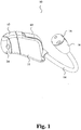
- Fig. 1 shows in perspective a first embodiment of a hearing instrument, namely a hearing aid, according to the present invention.
- Fig. 2 shows the embodiment of Fig. 1 positioned in the right ear of a user.
- the illustrated hearing aid has a housing 10 with a trunk part 11 and a right tip part 12 fitting into the right ear canal of the user.
- the right tip part 12 forms an angle towards the left in the medial direction with relation to the longitudinal extension of the trunk part 12 of the housing thereby comfortably fitting the right ear canal 220 for retention of the housing in the right ear of the user.
- the housing accommodates the hearing aid components, the tip part 12 of the housing 10 accommodating the receiver (not shown) for emission of sound through an output port (not shown) towards the eardrum of the user.
- the illustrated trunk part 11 of the housing 10 is substantially straight along its longitudinal extension and has a substantially rectangular cross-section both perpendicular to and in parallel with its longitudinal extension seen from the side and seen from above.
- the housing 10 further comprises an elongate member 14 that is attached to the trunk part 11 of the housing 10 and adapted for positioning within the pinna 200 during use. More specifically, the elongate member 14 is adapted to be positioned in the cimba concha 260 of the ear of the user. The elongate member 14 and the trunk part 11 of the housing 10 form separate units that are manufactured in separate pieces.
- the microphone of the hearing aid housing 10 is positioned at the microphone input port 16 at the second end 18 of the elongate member 14. The remaining parts of the housing 10 accommodate the other components. Signal conductors extend within the elongate member 14 for electrical interconnection of the microphone with the other components in the housing 10.
- Positioning of the microphone(s) of the hearing aid at the second end 18 of the elongate member 14 provides an increased distance between the microphone(s) and the output port as compared to the corresponding distance in conventional ITE and CIC hearing aids whereby feedback is diminished.
- trunk part 11 and elongate member 14 are manufactured as separate parts that are removably interconnected mechanically and electrically.
- the illustrated trunk part 11 of the housing 10 and the elongate member 14 are manufactured in a number of respective standard sizes to fit the human anatomy of the ear of most users. In this way, the manufacturing cost is lowered as compared to the manufacturing cost of customized housings.
- the elongate member 14 is removably interconnected with the trunk part 11 of the housing 10 so that a large number of different models of the hearing aid housing 10 may be provided by combining elongate members 14 of different standard sizes with trunk parts 11 of different standard sizes.
- the elongate member 14 is adapted to be positioned in the concha of the pinna 200 of the user and has a longitudinal shape with a first end 20 attached to the trunk part 11 of the housing 10 and an opposite second end 18.
- the elongate member 14 assists in retaining the housing 10 in the ear canal 220 of the user so that the housing 10 remains securely in place in the ear canal 220 without falling out of the ear. Retention is provided without causing pain to the user. Retention of the device in the proper place is important. Jaw movements during chewing for instance can exert outward forces on the housing 10 of the hearing aid. The elongate member 14 counteracts this force thereby sufficiently securing the housing 10 from outward motion.
- the illustrated elongate member 14 is resilient in a direction perpendicular to the longitudinal extension thereby providing further retention capability of the housing 10 in the ear canal 220 of the user.
- the transverse resilience of the elongate member 14 facilitates insertion of the housing 10 into the ear canal 220 of the user.
- the elongate member 14 is adapted to abut the antihelix 230 and extend to the inferior crus 250 of the antihelix so that the second end 18 is positioned at the cimba concha 260 of the ear below the triangular fossa when the hearing aid housing 10 is positioned in the ear of the user.
- the elongate member 14 has a larger cross-section at the second end 18 accommodating the microphone than a remaining part of the elongate member 14 extending therefrom and towards the first end 20.
- the elongate member 14 may accommodate further electrical hearing aid components.
- the illustrated elongate member 14 is substantially rigid in the direction of its longitudinal extension so that electrical conductors residing in the elongate member 14 are protected against breaking.
- Two microphones may be accommodated at the second end 18 of the elongate member 14 for provision of noise suppression and/or further directionality.
- the elongate member may further be adapted to abut part of the concha at the antitragus 280 when the housing 10 has been inserted in the ear canal 220 thereby applying a force to the housing 10 towards the ear canal retaining the housing 10 in a position in which the housing 10 is pressed against an anatomical feature within the ear canal.
- the illustrated embodiment further comprises a cerumen filter 24 that is fitted on the tip part 12 of the housing 10.
- the cerumen filter 24 is coupled to the tip part 12 by means of a snap fit coupling.
- Fig. 3 shows an embodiment of a hearing aid according to the present invention positioned in the left ear of a user.
- the illustrated hearing aid may have all of the features of the hearing aid shown in Figs. 1 and 2 .
- Fig. 4 shows in horizontal cross-section the positioning of the hearing aid housing 10 of Figs. 1 and 2 in the right ear canal 220 of a user.
- the cross-section of Fig. 4 is taken along line AB in Fig. 2 .
- the viewing direction is from above as indicated by the arrow in Fig. 2 .
- the tip part 12 of the housing 10 forms an angle towards the left in relation to the longitudinal extension of the trunk part 11 when seen from above and in the medial direction, i.e. from the entrance of the ear canal towards the ear drum.
- the bend towards the left facilitates accommodation of the housing 10 in the right ear canal 220 of the user.
- the tip part 12 is flexible for variation of the angle for accommodation of the housing 10 to varying angles of different users.
- the housing 10 is flexible for comfortable accommodation of the housing 10 in the ear canal of the user providing a high level of comfort.
- the illustrated housing 10 has a cross-section that is smaller than the cross-section of the ear canal 220 so that occlusion is reduced or eliminated.
- the smaller cross-section of the housing 10 allows communication between the ear canal between the eardrum and the housing 10 and the surroundings for prevention of occlusion.
- the illustrated hearing aid housing 10 is positioned completely in the ear canal of the user like a conventional CIC hearing aid.
- the outward pointing end of the hearing aid housing 10 with the battery door 60 is aligned with, or approximately aligned with, the cavum conchae 290, i.e.
- the battery door 60 coincides with, or approximately coincides with, the delimitation between the cavum conchae and the ear canal.
- the battery door 60 resides slightly inside the delimitation between the cavum conchae and the ear canal so that the entire housing 10 is accommodated within the ear canal of the user.
- Fig. 5 shows the physical dimensions of two exemplified embodiments of the invention.
- Fig. 6 shows from above the embodiment of Fig. 1 with an open battery door 60.
- the battery door 60 is provided at the lateral end of the trunk part 11 of the housing 10 pointing out of the ear canal when the hearing aid housing 10 is positioned in the ear.
- the battery door 60 has a compartment 62 accommodating the hearing aid battery (not shown).
- the user may open or close the battery door 60 by rotating the battery door around an axis of rotation provided by a hinge connection 72.
- the battery compartment 62 swings out of the trunk part 11 of the housing 10 when the battery door 60 is opened whereby the battery may be exchanged with a new battery.
- the elongate member 14 is attached to the battery door 60 and the battery door 60 is removably attached to the trunk part 11 of the housing 10 with a connector 64 including the hinge connection 72.
- the hinge connection 72 has a shaft 74
- the battery door 60 has a flexible recess 76 so that a person may attach the battery door 60 to the trunk part 11 by pressing the recess 76 around the shaft 74 whereby the recess 76 expands slightly to accommodate the shaft 74 and snaps back for retention of the shaft within the recess.
- the user may remove the battery door 60 from the trunk part 11 by pulling the battery door 60 away from the trunk part 11 whereby the recess expands to release the shaft and snaps back into its original relaxed shape upon release of the shaft 74.
- the illustrated snap fit coupling for interconnection of the battery door 60 with the trunk part 11 is designed so that the force required to separate the battery door 60 from the trunk part 11 is larger than the force required to pull the hearing aid housing 10 out of the ear canal of the user by pulling the elongate member 14.
- the illustrated hearing aid housing connector 64 further comprises resilient electrical contact members 66 for electrical interconnection of signal conductors in the elongate member 14 with electrical components in the housing 10.
- the illustrated embodiment has three contact members 66, however other embodiments may have more than three contact members.
- Fig. 7 shows the hearing aid housing 10 with the battery door 60 removed
- Fig. 8 shows the removed battery door 60 with the elongate member 14.
- electrical contact members 68 of the interconnected battery door 60 and elongate member 14 mating the contact members 66 of the hearing aid housing connector 64 connect slidably with respective electrical contact members 66 of the trunk part 11 when the battery compartment 62 is closed by rotation.
- the sliding connection provides a cleaning action thereby cleaning the contact surfaces maintaining a low contact resistance across the electrical interconnection of the hearing aid components, e.g. by mechanical removal of oxide film formed on the contact surfaces, or mechanical removal of other undesired deposits on the contact surfaces.
- the elongate member 14 is removably connected directly with the trunk part 11 of the hearing aid housing 10.
- the elongate member 14 has an electrical connector at its second end mating a corresponding hearing aid housing connector.
- the elongate member 14 with the connector is inserted through a hole provided in the hearing aid housing 10.
- the battery door 60 may be provided with a suitable mechanical member that assists in attaching the elongate member 14 to the trunk part 11 of the hearing aid housing 10 by abutment with the elongate member 14 when the battery door 60 is closed.
- the battery door may include locking means preventing the battery door from being inadvertently opened e.g. due to forces applied to the elongate member 14.
- Figs. 9 (a) - (c) illustrate positioning of a microphone 2a at the second end 18 of an elongate member 14 in accordance with an embodiment of the invention.
- the microphone 2a and its signal conductors 17 are inserted into the elongate member 14 through an open second end 18 of the elongate member 14, and the microphone 2a is pushed into its desired position shown in Fig. 9 (b) .
- the signal conductors 17 with the signal line of the microphone 2a extend inside the elongate member 14.
- a threaded cap 19 with a dirt filter closes the opening of the elongate member 14 as illustrated in Fig. 9 (c) .
- the dirt filter at this position protects the microphone against sweat, dirt, dead cells, etc., from the pinna.
- a cerumen filter may be used as the dirt filter.
- Fig. 10 illustrates the interconnection of the signal conductors 17 with the contact members 68 in accordance with an embodiment of the invention.
- the contact members 68 are provided on a slide member that may slide into a mating compartment in the battery door for positioning of the contact members 68 as for example illustrated in Fig. 8 .
- the exposed ends of the signal conductors 17 are soldered onto the contact members 68 provided on the slide member.
- the slide member is inserted into the battery door 60 and possibly glued to the battery door.
- Fig. 11 shows a set of hearing aid housing parts according to the invention.
- the set comprises a trunk part 11 configured for interconnection with a tip part 12 R , 12 L and that is substantially straight along its longitudinal extension. Further, the set comprises a right tip part 12 R that forms an angle facilitating accommodation in the right ear canal of the user, and a left tip part 12 L that forms an angle facilitating accommodation in the left ear canal of the user of a hearing aid housing 10.
- a straight tip part (not shown) that is straight and extends along the longitudinal extension of the trunk part when interconnected with the trunk part may also be provided.
- the illustrated set of hearing aid housing parts further comprises a receiver 102 and a cerumen filter 24, and a left ear battery door 60 L to be removably attached to the trunk part 11 of the housing 10 and attached to the elongate member 14 at an angle suitable for use in the left ear, and a right ear battery door 60 R removably attached to the trunk part 11 of the housing 10 and attached to the elongate member 14 at an angle suitable for use in the right ear.
- Each of the parts illustrated in Fig. 11 may be manufactured in a variety of standard sizes and shapes whereby a large variety of housings may be provided based on combinations of a relatively few number of standard sized and shaped parts. In this way, the dispenser will be able to offer users a large variety of housings in an economical way that does not require purchase and storage of a large number of different housings.
- Figs. 12 and 13 show the Signal Processor Module 110 forming an end wall of the trunk part 11 of the housing 10.
- the Signal Processor Module 110 holds the signal processor (not shown) and has a number of connector pads for interconnection with other electrical components of the hearing aid.
- the springs 118 are soldered to the two connector pads 112 for interconnection of the Signal Processor Module 110 with the battery. When the battery door with the battery in the battery compartment is closed, the battery swings in between the springs 118 that are pressed against the respective flat surfaces of the battery and thereby interconnect the plus and minus terminals of the battery with the Signal Processor Module 110.
- the springs 118 may be extended to the outer surface of the housing 10 for provision of readily accessible contacts for recharging of the rechargeable battery.
- the receiver is soldered onto the two connector pads 114.
- the Signal Processor Module has a connector mechanically mating with the receiver for interconnection of the receiver with the Signal Processor Module without soldering.
- the three springs 66 are soldered onto the respective connector pads 116 and interconnect the Signal Processor Module 110 with the signal lines in the elongate member as previously explained in connection with Fig. 7 .
- the springs 66, 118 may provide a snap fit coupling of the Signal Processor Module 110 by provision of protrusions.
- the module 110 is pressed passed the resilient protrusions of the springs 66, 118 that allow passage of the board and spring back after full insertion of the Signal Processor Module into the trunk part 11 of the housing 10 thereby holding the Signal Processor Module 110 in a fixed position in the trunk part 11.
- the Signal Processor Module acts as a sound barrier for increased internal stability of the hearing aid circuitry.
- the receiver may be installed in the hearing aid housing 10 by the dispenser so that the dispenser may be able to offer a variety of models to the user without a need for purchasing and storing a similar variety of hearing aids.
- Fig. 14 shows the Signal Processor Module 110 forming an end wall of the trunk part 11 of the housing 10 from the opposite side of Figs. 12 and 13 . From this side, the connector pads 120 for the programming of the hearing instrument are accessible.
- a programming connector (not shown) of the programming equipment for the hearing device is inserted in the battery compartment of the illustrated housing 10 for electrical interconnection with the connector pads 120.
- the programming connector may mechanically engage with the springs 118 for keeping the programming connector in a fixed position during programming.
- the battery door may be closed for retaining the programming connector (not shown) in the battery compartment.
- any selected set of contacts from the group consisting of the springs 118 and the contact members 66 may be used for programming of the hearing instrument.
- Fig. 15 shows a simplified block diagram of a digital hearing aid according to the present invention.
- the hearing aid 1 comprises one or more sound receivers 2, e.g. two microphones 2a and a telecoil 2b.
- the analogue signals for the microphones are coupled to an analogue-digital converter circuit 3, which contains an analogue-digital converter 4 for each of the microphones.
- the digital signal outputs from the analogue-digital converters 4 are coupled to a common data line 5, which leads the signals to a digital signal processor (DSP) 6.
- DSP digital signal processor
- the DSP is programmed to perform the necessary signal processing operations of digital signals to compensate hearing loss in accordance with the needs of the user.
- the DSP is further programmed for automatic adjustment of signal processing parameters in accordance with the present invention.
- the output signal is then fed to a digital-analogue converter 12, from which analogue output signals are fed to a sound transducer 13, such as a miniature loudspeaker.
- a digital-analogue converter 12 from which analogue output signals are fed to a sound transducer 13, such as a miniature loudspeaker.
- the hearing aid contains a storage unit 14, which in the example shown is an EEPROM (electronically erasable programmable read-only memory).
- This external memory 14, which is connected to a common serial data bus 5, can be provided via an interface 15 with programmes, data, parameters etc. entered from a PC 16, for example, when a new hearing aid is allotted to a specific user, where the hearing aid is adjusted for precisely this user, or when a user has his hearing aid updated and/or re-adjusted to the user's actual hearing loss, e.g. by an audiologist.
- the DSP 6 contains a central processor (CPU) 7 and a number of internal storage units 8-11, these storage units containing data and programmes, which are presently being executed in the DSP circuit 6.
- the DSP 6 contains a programme-ROM (read-only memory) 8, a data-ROM 9, a programme-RAM (random access memory) 10 and a data-RAM 11.
- the two first-mentioned contain programmes and data which constitute permanent elements in the circuit, while the two last-mentioned contain programmes and data which can be changed or overwritten.
- the housing 10 of the illustrated hearing aid accommodates the above-mentioned hearing aid components except the microphone in a way similar to the housing 10 of a CIC hearing aid.
- the elongate member accommodates the microphone, e.g. at its second end, and signal conductors extend within the elongate member for electrical interconnection of the microphone with the components in the hearing aid housing 10.
- the receiver is accommodated in the tip part of the housing 10.
- the external EEPROM 14 is considerably larger, e.g. 4-8 times larger, than the internal RAM, which means that certain data and programmes can be stored in the EEPROM so that they can be read into the internal RAMs for execution as required. Later, these special data and programmes may be overwritten by the normal operational data and working programmes.
- the external EEPROM can thus contain a series of programmes, which are used only in special cases, such as e.g. start-up programmes.
- FIG. 16 A block diagram of an embodiment of a hearing aid with a feedback compensation filter 106 is shown in Fig. 16 .
- the hearing aid comprises a microphone 101 for receiving incoming sound and converting it into an audio signal.
- a receiver 102 converts output from the hearing aid processor 103 into output sound, which in, e.g., a hearing aid is supposed to be modified to compensate for a users hearing impairment.
- the hearing aid processor 103 comprises elements such as amplifiers, compressors and noise reduction systems etc.
- a feedback path 104 is shown as a dashed line between the receiver 102 and the microphone 101. Due to the feedback path, the microphone 101 may pick up sound from the receiver 102 which may lead to well known feedback problems, such as whistling.
- H ⁇ A ⁇ 1 ⁇ F ⁇ A ⁇
- w represents (angular) frequency
- F(w) is the gain function of the feedback path 104
- A(w) is the gain function provided by the hearing aid processor 103.
- the feedback compensation filter 106 is adapted to feed a compensation signal to the subtraction unit 105, whereby the compensation signal is subtracted from the audio signal provided by the microphone 101 prior to processing in the hearing aid processor 103.
- F'(w) estimates the true gain function F(w) of the feedback path, the closer H(w) will be to the desired gain function A(w).
- the feedback path 104 is usually a combination of internal and external feedback paths and acoustical and mechanical feedback paths.
Landscapes
- Engineering & Computer Science (AREA)
- Health & Medical Sciences (AREA)
- General Health & Medical Sciences (AREA)
- Neurosurgery (AREA)
- Otolaryngology (AREA)
- Physics & Mathematics (AREA)
- Acoustics & Sound (AREA)
- Signal Processing (AREA)
- Manufacturing & Machinery (AREA)
- Headphones And Earphones (AREA)
- Measurement Of The Respiration, Hearing Ability, Form, And Blood Characteristics Of Living Organisms (AREA)
- Structure Of Receivers (AREA)
Claims (15)
- Instrument d'audition avec un logement (10) pour loger un microphone,
un processeur de signal (6) pour produire un signal audio, et
un récepteur (102) qui est relié à une sortie du processeur de signal (6) pour transformer le signal audio en un signal de son, dans lequel
le logement (10) a une partie formant tronc (11) qui est interconnectée avec une partie formant embout (12) logeant le récepteur, et dans lequel
le logement (10) loge en outre une carte à circuit imprimé (110) qui forme une paroi à l'intérieur du logement (10) s'étendant transversalement à l'extension longitudinale de la partie formant tronc (11), et dans lequel
le processeur de signal (6) est positionné sur la carte à circuit imprimé (110), et dans lequel
le microphone et le récepteur sont positionnés sur des côtés opposés de la carte à circuit imprimé,
caractérisé en ce que
la paroi s'étend d'un bout à l'autre de la section transversale entière du logement d'instrument d'audition et scelle le volume intérieur sur un côté de la paroi à partir du volume intérieur résidant de l'autre côté de la paroi. - Instrument d'audition selon la revendication 1, dans lequel le logement (10) n'entrave pas le canal auriculaire quand il est positionné dans sa position opérationnelle prévue dans le canal auriculaire.
- Instrument d'audition selon la revendication 1 ou 2, dans lequel la carte à circuit imprimé (110) forme une paroi dans la partie formant tronc (11) du logement (10).
- Instrument d'audition selon l'une quelconque des revendications précédentes, dans lequel la carte à circuit imprimé (110) comprend en outre des plages de connexion de connecteur (114) pour connexion avec un équipement de programmation pour l'instrument d'audition.
- Instrument d'audition selon l'une quelconque des revendications précédentes, dans lequel la carte à circuit imprimé (110) comprend en outre des plages de connexion de connecteur (114) pour connexion avec le récepteur (102), et dans lequel la partie formant tronc (11) du logement (10) comprend en outre un connecteur pour établir un contact mécanique et électrique avec le récepteur (102).
- Instrument d'audition selon l'une quelconque des revendications précédentes, dans lequel la carte à circuit imprimé (110) comprend en outre des plages de connexion de connecteur (112) pour connexion avec une batterie pour l'alimentation en énergie des circuits d'instrument d'audition.
- Instrument d'audition selon la revendication 6, comprenant en outre des premiers ressorts (118) interconnectés avec les plages de connexion de connecteur (112) pour interconnexion de la carte à circuit imprimé (110) avec la batterie.
- Instrument d'audition selon la revendication 7, dans lequel les premiers ressorts (118) fournissent un accouplement par ajustement par encliquetage mécanique de la carte à circuit imprimé (110) au logement d'instrument d'audition (10).
- Instrument d'audition selon l'une quelconque des revendications 6 à 8, dans lequel la carte à circuit imprimé (110) comprend en outre des plages de connexion de connecteur (116) pour connexion avec des lignes de signal (17) dans un élément allongé (14), et comprenant en outre des seconds ressorts (66) interconnectés avec les plages de connexion de connecteur (116) pour l'interconnexion de la carte à circuit imprimé (119) avec les lignes de signal (17) dans l'élément allongé (14) qui est attaché au logement (10) et dans lequel l'élément allongé (14) est conçu pour se positionner dans le pavillon et à l'extérieur du canal auriculaire (220) de l'utilisateur pour la retenue du logement (10) dans le canal auriculaire (220).
- Instrument d'audition selon la revendication 9, dans lequel les seconds ressorts (66) fournissent un accouplement par ajustement par encliquetage mécanique de la carte à circuit imprimé (110) au logement d'instrument d'audition (10).
- Instrument d'audition selon l'une quelconque des revendications précédentes, dans lequel la carte à circuit imprimé (110) est moulée dans une matière protectrice.
- Instrument d'audition selon l'une quelconque des revendications 9 à 11, dans lequel l'élément allongé (14) est attaché de façon amovible au logement (10).
- Instrument d'audition selon l'une quelconque des revendications 9 à 12, dans lequel l'élément allongé (14) a une forme longitudinale avec une première extrémité (20) attachée au logement (10) et une seconde extrémité opposée (18).
- Instrument d'audition selon l'une quelconque des revendications précédentes, dans lequel le logement (10) comprend une trappe de batterie (60) attachée de façon amovible à la partie formant tronc (11) du logement (10) et dans lequel l'élément allongé (14) est attaché à la trappe de batterie (60).
- Instrument d'audition selon la revendication 14, dans lequel le logement (10) comprend en outre un connecteur pour établir un contact électrique avec une ligne de signal (17) dans l'élément allongé (14) lorsque la trappe de batterie (60) est attachée au logement (10).
Applications Claiming Priority (3)
| Application Number | Priority Date | Filing Date | Title |
|---|---|---|---|
| US1708707P | 2007-12-27 | 2007-12-27 | |
| DKPA200701880 | 2007-12-27 | ||
| PCT/DK2008/000449 WO2009083007A2 (fr) | 2007-12-27 | 2008-12-22 | Appareil auditif à paroi constituée d'une carte à circuit imprimé |
Publications (2)
| Publication Number | Publication Date |
|---|---|
| EP2238773A2 EP2238773A2 (fr) | 2010-10-13 |
| EP2238773B1 true EP2238773B1 (fr) | 2017-02-08 |
Family
ID=39493908
Family Applications (1)
| Application Number | Title | Priority Date | Filing Date |
|---|---|---|---|
| EP08869117.5A Active EP2238773B1 (fr) | 2007-12-27 | 2008-12-22 | Appareil auditif à paroi constituée d'une carte à circuit imprimé |
Country Status (5)
| Country | Link |
|---|---|
| US (1) | US9232324B2 (fr) |
| EP (1) | EP2238773B1 (fr) |
| JP (1) | JP6144865B2 (fr) |
| CN (2) | CN107426659A (fr) |
| WO (1) | WO2009083007A2 (fr) |
Families Citing this family (14)
| Publication number | Priority date | Publication date | Assignee | Title |
|---|---|---|---|---|
| NL1033281C2 (nl) * | 2006-07-21 | 2008-01-22 | Exsilent Res Bv | Hoortoestel, uitbreidingseenheid en werkwijze voor het vervaardigen van een hoortoestel. |
| US20110022032A1 (en) * | 2007-10-05 | 2011-01-27 | Tyco Healthcare Group Lp | Battery ejection design for a surgical device |
| DK2594089T3 (da) * | 2010-08-20 | 2014-08-11 | Siemens Medical Instr Pte Ltd | Mikrofonbeskyttelsesindretning |
| EP2587838B1 (fr) * | 2011-10-25 | 2018-03-07 | Oticon A/S | Accessoire de retenue d'aide auditive |
| DE102013001920B3 (de) * | 2013-02-05 | 2014-08-07 | Phonak Ag | Lautsprecher-Ohrstück für ein Hörgerät |
| US9648429B2 (en) * | 2013-05-10 | 2017-05-09 | Starkey Laboratories, Inc. | Hearing assistance device with improved microphone protection |
| US9479859B2 (en) | 2013-11-18 | 2016-10-25 | 3M Innovative Properties Company | Concha-fit electronic hearing protection device |
| US20170325036A1 (en) * | 2014-10-09 | 2017-11-09 | Sonova Ag | Hearing device |
| US20160119727A1 (en) * | 2014-10-27 | 2016-04-28 | Sidney A. Higgins | Sinter bonded mu-metal receiver can |
| DK3145219T3 (da) | 2015-09-21 | 2021-07-26 | Oticon As | Høreanordning |
| DK3367703T3 (da) * | 2017-02-27 | 2020-07-06 | Oticon As | Høreanordning med en mikrofonstruktur |
| EP3664474B1 (fr) | 2018-12-04 | 2023-02-08 | Oticon A/s | Ensemble haut-parleur pour prothèse auditive |
| US11290804B1 (en) | 2021-07-29 | 2022-03-29 | David Beavers | Sound control ear cup, tinnitus treatment device, and hearing protection device |
| CN116236191A (zh) * | 2022-12-06 | 2023-06-09 | 江苏米笛声学科技有限公司 | 一种用于听力障碍的患者检测应答器 |
Citations (3)
| Publication number | Priority date | Publication date | Assignee | Title |
|---|---|---|---|---|
| JPH1066196A (ja) * | 1996-08-22 | 1998-03-06 | Rion Co Ltd | 耳あな形補聴器 |
| WO2001008444A2 (fr) * | 1999-07-23 | 2001-02-01 | Sarnoff Corporation | Appareil auditif |
| WO2001008443A2 (fr) * | 1999-07-23 | 2001-02-01 | Sarnoff Corporation | Appareil auditif unitaille s'adaptant indifferemment dans les deux oreilles |
Family Cites Families (36)
| Publication number | Priority date | Publication date | Assignee | Title |
|---|---|---|---|---|
| US3783201A (en) * | 1970-12-02 | 1974-01-01 | Beltone Electronics Corp | Miniature hearing aid structure |
| GB2134689A (en) | 1983-01-26 | 1984-08-15 | Nat Res Dev | Tinnitus masking |
| CA1221315A (fr) * | 1984-10-19 | 1987-05-05 | William J. Gastmeier | Protecteur pour appareil acoustique |
| DE3511792A1 (de) | 1985-03-30 | 1986-10-02 | Robert Bosch Gmbh, 7000 Stuttgart | Im ohrkanal zu tragendes hoergeraet |
| DE8814162U1 (de) * | 1988-11-11 | 1988-12-29 | Hörgeräte Geers GmbH & Co. KG, 4600 Dortmund | Hörgerät |
| DK0491072T3 (da) * | 1990-12-18 | 1995-10-16 | Siemens Ag | Høreapparat |
| US5680467A (en) | 1992-03-31 | 1997-10-21 | Gn Danavox A/S | Hearing aid compensating for acoustic feedback |
| DK169958B1 (da) | 1992-10-20 | 1995-04-10 | Gn Danavox As | Høreapparat med kompensation for akustisk tilbagekobling |
| US5403262A (en) | 1993-03-09 | 1995-04-04 | Microtek Medical, Inc. | Minimum energy tinnitus masker |
| DE19504478C2 (de) | 1995-02-10 | 1996-12-19 | Siemens Audiologische Technik | Gehörgangseinsatz für Hörhilfen |
| US5606621A (en) | 1995-06-14 | 1997-02-25 | Siemens Hearing Instruments, Inc. | Hybrid behind-the-ear and completely-in-canal hearing aid |
| GB2305067A (en) | 1995-09-02 | 1997-03-26 | A & M Hearing Ltd | Hearing aid having hinged housing |
| US20010040973A1 (en) * | 1997-03-12 | 2001-11-15 | Sarnoff Corporation | Hearing aid with tinted components |
| US7027608B2 (en) | 1997-07-18 | 2006-04-11 | Gn Resound North America | Behind the ear hearing aid system |
| DE29718503U1 (de) | 1997-10-17 | 1999-02-18 | Lux-Wellenhof, Gabriele, 65830 Kriftel | Gerät zur Behandlung von Tinitus und Hyperakusis |
| US6498858B2 (en) | 1997-11-18 | 2002-12-24 | Gn Resound A/S | Feedback cancellation improvements |
| US6389143B1 (en) * | 1998-07-14 | 2002-05-14 | Sarnoff Corporation | Modular electroacoustic instrument |
| US20010051776A1 (en) | 1998-10-14 | 2001-12-13 | Lenhardt Martin L. | Tinnitus masker/suppressor |
| AUPP927599A0 (en) | 1999-03-17 | 1999-04-15 | Curtin University Of Technology | Tinnitus rehabilitation device and method |
| US6876749B1 (en) * | 1999-07-12 | 2005-04-05 | Etymotic Research, Inc. | Microphone for hearing aid and communications applications having switchable polar and frequency response characteristics |
| US6704423B2 (en) | 1999-12-29 | 2004-03-09 | Etymotic Research, Inc. | Hearing aid assembly having external directional microphone |
| US7130437B2 (en) | 2000-06-29 | 2006-10-31 | Beltone Electronics Corporation | Compressible hearing aid |
| WO2002052890A1 (fr) * | 2000-12-22 | 2002-07-04 | Nextlink.To A/S | Dispositif acoustique avec moyens permettant un maintien securise dans une oreille humaine |
| WO2003030772A2 (fr) | 2001-10-05 | 2003-04-17 | Advanced Bionics Corporation | Module de microphone destine a etre utilise avec un appareil auditif ou un systeme d'implant cochleaire |
| AU2002368107A1 (en) | 2002-07-18 | 2004-02-09 | Insound Medical, Inc. | Canal hearing device with tubular insert |
| US7751580B2 (en) * | 2002-09-10 | 2010-07-06 | Auditory Licensing Company, Llc | Open ear hearing aid system |
| JP4619410B2 (ja) * | 2004-09-07 | 2011-01-26 | ヴェーデクス・アクティーセルスカプ | 補聴器用イヤピースおよび補聴器 |
| EP1819500B1 (fr) * | 2004-11-26 | 2011-01-26 | GN Resound A/S | Support et methode pour le façonnage d'un tube acoustique |
| US7844065B2 (en) | 2005-01-14 | 2010-11-30 | Phonak Ag | Hearing instrument |
| DE102005006856B3 (de) | 2005-02-15 | 2006-08-03 | Siemens Audiologische Technik Gmbh | Hörhilfegerät mit einem Bedienelement |
| US8792663B2 (en) | 2005-08-01 | 2014-07-29 | Gn Resound A/S | Hearing device with an open earpiece having a short vent |
| DE102005045896A1 (de) | 2005-09-26 | 2007-04-19 | Siemens Audiologische Technik Gmbh | Hörgeräteprogrammierbuchse zur automatischen Leiterplattenbestückung |
| US7756284B2 (en) * | 2006-01-30 | 2010-07-13 | Songbird Hearing, Inc. | Hearing aid circuit with integrated switch and battery |
| US7715582B2 (en) | 2006-02-06 | 2010-05-11 | Phonak Ag | Hearing device with locking system for connectors |
| US20070195981A1 (en) * | 2006-02-23 | 2007-08-23 | Le Anthony D | Behind-the-ear hearing aid with integrally-molded instrument case |
| US7856111B2 (en) * | 2006-10-04 | 2010-12-21 | Siemens Audiologische Technik Gmbh | Hearing aid with sound tube serving for retention in concha |
-
2008
- 2008-12-22 WO PCT/DK2008/000449 patent/WO2009083007A2/fr active Application Filing
- 2008-12-22 CN CN201610872101.7A patent/CN107426659A/zh active Pending
- 2008-12-22 JP JP2010540028A patent/JP6144865B2/ja active Active
- 2008-12-22 CN CN2008801267652A patent/CN101965737A/zh active Pending
- 2008-12-22 EP EP08869117.5A patent/EP2238773B1/fr active Active
- 2008-12-22 US US12/810,816 patent/US9232324B2/en active Active
Patent Citations (3)
| Publication number | Priority date | Publication date | Assignee | Title |
|---|---|---|---|---|
| JPH1066196A (ja) * | 1996-08-22 | 1998-03-06 | Rion Co Ltd | 耳あな形補聴器 |
| WO2001008444A2 (fr) * | 1999-07-23 | 2001-02-01 | Sarnoff Corporation | Appareil auditif |
| WO2001008443A2 (fr) * | 1999-07-23 | 2001-02-01 | Sarnoff Corporation | Appareil auditif unitaille s'adaptant indifferemment dans les deux oreilles |
Also Published As
| Publication number | Publication date |
|---|---|
| US9232324B2 (en) | 2016-01-05 |
| EP2238773A2 (fr) | 2010-10-13 |
| WO2009083007A2 (fr) | 2009-07-09 |
| US20110280423A1 (en) | 2011-11-17 |
| JP2011508547A (ja) | 2011-03-10 |
| CN101965737A (zh) | 2011-02-02 |
| CN107426659A (zh) | 2017-12-01 |
| JP6144865B2 (ja) | 2017-06-07 |
| WO2009083007A3 (fr) | 2009-09-17 |
Similar Documents
| Publication | Publication Date | Title |
|---|---|---|
| EP2238773B1 (fr) | Appareil auditif à paroi constituée d'une carte à circuit imprimé | |
| EP2238772B1 (fr) | Appareil auditif modulaire | |
| US8634582B2 (en) | Hearing aid with an elongate member | |
| US8792663B2 (en) | Hearing device with an open earpiece having a short vent | |
| US8374367B2 (en) | Hearing aid with a flexible elongated member | |
| DK2033486T3 (en) | Hearing aid with a removably connected, elongated member | |
| DK2238773T3 (en) | Hearing aid with a wall formed by a printed circuit board |
Legal Events
| Date | Code | Title | Description |
|---|---|---|---|
| PUAI | Public reference made under article 153(3) epc to a published international application that has entered the european phase |
Free format text: ORIGINAL CODE: 0009012 |
|
| 17P | Request for examination filed |
Effective date: 20100727 |
|
| AK | Designated contracting states |
Kind code of ref document: A2 Designated state(s): AT BE BG CH CY CZ DE DK EE ES FI FR GB GR HR HU IE IS IT LI LT LU LV MC MT NL NO PL PT RO SE SI SK TR |
|
| AX | Request for extension of the european patent |
Extension state: AL BA MK RS |
|
| DAX | Request for extension of the european patent (deleted) | ||
| 17Q | First examination report despatched |
Effective date: 20141027 |
|
| GRAP | Despatch of communication of intention to grant a patent |
Free format text: ORIGINAL CODE: EPIDOSNIGR1 |
|
| INTG | Intention to grant announced |
Effective date: 20160823 |
|
| GRAS | Grant fee paid |
Free format text: ORIGINAL CODE: EPIDOSNIGR3 |
|
| GRAA | (expected) grant |
Free format text: ORIGINAL CODE: 0009210 |
|
| AK | Designated contracting states |
Kind code of ref document: B1 Designated state(s): AT BE BG CH CY CZ DE DK EE ES FI FR GB GR HR HU IE IS IT LI LT LU LV MC MT NL NO PL PT RO SE SI SK TR |
|
| REG | Reference to a national code |
Ref country code: GB Ref legal event code: FG4D |
|
| REG | Reference to a national code |
Ref country code: CH Ref legal event code: EP Ref country code: AT Ref legal event code: REF Ref document number: 867320 Country of ref document: AT Kind code of ref document: T Effective date: 20170215 |
|
| REG | Reference to a national code |
Ref country code: IE Ref legal event code: FG4D |
|
| REG | Reference to a national code |
Ref country code: DK Ref legal event code: T3 Effective date: 20170314 |
|
| REG | Reference to a national code |
Ref country code: DE Ref legal event code: R096 Ref document number: 602008048722 Country of ref document: DE |
|
| REG | Reference to a national code |
Ref country code: LT Ref legal event code: MG4D |
|
| REG | Reference to a national code |
Ref country code: NL Ref legal event code: MP Effective date: 20170208 |
|
| REG | Reference to a national code |
Ref country code: AT Ref legal event code: MK05 Ref document number: 867320 Country of ref document: AT Kind code of ref document: T Effective date: 20170208 |
|
| PG25 | Lapsed in a contracting state [announced via postgrant information from national office to epo] |
Ref country code: GR Free format text: LAPSE BECAUSE OF FAILURE TO SUBMIT A TRANSLATION OF THE DESCRIPTION OR TO PAY THE FEE WITHIN THE PRESCRIBED TIME-LIMIT Effective date: 20170509 Ref country code: LT Free format text: LAPSE BECAUSE OF FAILURE TO SUBMIT A TRANSLATION OF THE DESCRIPTION OR TO PAY THE FEE WITHIN THE PRESCRIBED TIME-LIMIT Effective date: 20170208 Ref country code: NO Free format text: LAPSE BECAUSE OF FAILURE TO SUBMIT A TRANSLATION OF THE DESCRIPTION OR TO PAY THE FEE WITHIN THE PRESCRIBED TIME-LIMIT Effective date: 20170508 Ref country code: FI Free format text: LAPSE BECAUSE OF FAILURE TO SUBMIT A TRANSLATION OF THE DESCRIPTION OR TO PAY THE FEE WITHIN THE PRESCRIBED TIME-LIMIT Effective date: 20170208 Ref country code: HR Free format text: LAPSE BECAUSE OF FAILURE TO SUBMIT A TRANSLATION OF THE DESCRIPTION OR TO PAY THE FEE WITHIN THE PRESCRIBED TIME-LIMIT Effective date: 20170208 |
|
| PG25 | Lapsed in a contracting state [announced via postgrant information from national office to epo] |
Ref country code: LV Free format text: LAPSE BECAUSE OF FAILURE TO SUBMIT A TRANSLATION OF THE DESCRIPTION OR TO PAY THE FEE WITHIN THE PRESCRIBED TIME-LIMIT Effective date: 20170208 Ref country code: NL Free format text: LAPSE BECAUSE OF FAILURE TO SUBMIT A TRANSLATION OF THE DESCRIPTION OR TO PAY THE FEE WITHIN THE PRESCRIBED TIME-LIMIT Effective date: 20170208 Ref country code: SE Free format text: LAPSE BECAUSE OF FAILURE TO SUBMIT A TRANSLATION OF THE DESCRIPTION OR TO PAY THE FEE WITHIN THE PRESCRIBED TIME-LIMIT Effective date: 20170208 Ref country code: BG Free format text: LAPSE BECAUSE OF FAILURE TO SUBMIT A TRANSLATION OF THE DESCRIPTION OR TO PAY THE FEE WITHIN THE PRESCRIBED TIME-LIMIT Effective date: 20170508 Ref country code: PT Free format text: LAPSE BECAUSE OF FAILURE TO SUBMIT A TRANSLATION OF THE DESCRIPTION OR TO PAY THE FEE WITHIN THE PRESCRIBED TIME-LIMIT Effective date: 20170608 Ref country code: AT Free format text: LAPSE BECAUSE OF FAILURE TO SUBMIT A TRANSLATION OF THE DESCRIPTION OR TO PAY THE FEE WITHIN THE PRESCRIBED TIME-LIMIT Effective date: 20170208 Ref country code: ES Free format text: LAPSE BECAUSE OF FAILURE TO SUBMIT A TRANSLATION OF THE DESCRIPTION OR TO PAY THE FEE WITHIN THE PRESCRIBED TIME-LIMIT Effective date: 20170208 |
|
| PG25 | Lapsed in a contracting state [announced via postgrant information from national office to epo] |
Ref country code: RO Free format text: LAPSE BECAUSE OF FAILURE TO SUBMIT A TRANSLATION OF THE DESCRIPTION OR TO PAY THE FEE WITHIN THE PRESCRIBED TIME-LIMIT Effective date: 20170208 Ref country code: CZ Free format text: LAPSE BECAUSE OF FAILURE TO SUBMIT A TRANSLATION OF THE DESCRIPTION OR TO PAY THE FEE WITHIN THE PRESCRIBED TIME-LIMIT Effective date: 20170208 Ref country code: SK Free format text: LAPSE BECAUSE OF FAILURE TO SUBMIT A TRANSLATION OF THE DESCRIPTION OR TO PAY THE FEE WITHIN THE PRESCRIBED TIME-LIMIT Effective date: 20170208 Ref country code: EE Free format text: LAPSE BECAUSE OF FAILURE TO SUBMIT A TRANSLATION OF THE DESCRIPTION OR TO PAY THE FEE WITHIN THE PRESCRIBED TIME-LIMIT Effective date: 20170208 Ref country code: IT Free format text: LAPSE BECAUSE OF FAILURE TO SUBMIT A TRANSLATION OF THE DESCRIPTION OR TO PAY THE FEE WITHIN THE PRESCRIBED TIME-LIMIT Effective date: 20170208 |
|
| REG | Reference to a national code |
Ref country code: DE Ref legal event code: R097 Ref document number: 602008048722 Country of ref document: DE |
|
| PG25 | Lapsed in a contracting state [announced via postgrant information from national office to epo] |
Ref country code: PL Free format text: LAPSE BECAUSE OF FAILURE TO SUBMIT A TRANSLATION OF THE DESCRIPTION OR TO PAY THE FEE WITHIN THE PRESCRIBED TIME-LIMIT Effective date: 20170208 |
|
| PLBE | No opposition filed within time limit |
Free format text: ORIGINAL CODE: 0009261 |
|
| STAA | Information on the status of an ep patent application or granted ep patent |
Free format text: STATUS: NO OPPOSITION FILED WITHIN TIME LIMIT |
|
| REG | Reference to a national code |
Ref country code: FR Ref legal event code: PLFP Year of fee payment: 10 |
|
| 26N | No opposition filed |
Effective date: 20171109 |
|
| PG25 | Lapsed in a contracting state [announced via postgrant information from national office to epo] |
Ref country code: SI Free format text: LAPSE BECAUSE OF FAILURE TO SUBMIT A TRANSLATION OF THE DESCRIPTION OR TO PAY THE FEE WITHIN THE PRESCRIBED TIME-LIMIT Effective date: 20170208 |
|
| REG | Reference to a national code |
Ref country code: IE Ref legal event code: MM4A |
|
| PG25 | Lapsed in a contracting state [announced via postgrant information from national office to epo] |
Ref country code: LU Free format text: LAPSE BECAUSE OF NON-PAYMENT OF DUE FEES Effective date: 20171222 Ref country code: MT Free format text: LAPSE BECAUSE OF NON-PAYMENT OF DUE FEES Effective date: 20171222 |
|
| REG | Reference to a national code |
Ref country code: BE Ref legal event code: MM Effective date: 20171231 |
|
| PG25 | Lapsed in a contracting state [announced via postgrant information from national office to epo] |
Ref country code: IE Free format text: LAPSE BECAUSE OF NON-PAYMENT OF DUE FEES Effective date: 20171222 |
|
| PG25 | Lapsed in a contracting state [announced via postgrant information from national office to epo] |
Ref country code: BE Free format text: LAPSE BECAUSE OF NON-PAYMENT OF DUE FEES Effective date: 20171231 |
|
| PG25 | Lapsed in a contracting state [announced via postgrant information from national office to epo] |
Ref country code: HU Free format text: LAPSE BECAUSE OF FAILURE TO SUBMIT A TRANSLATION OF THE DESCRIPTION OR TO PAY THE FEE WITHIN THE PRESCRIBED TIME-LIMIT; INVALID AB INITIO Effective date: 20081222 Ref country code: MC Free format text: LAPSE BECAUSE OF FAILURE TO SUBMIT A TRANSLATION OF THE DESCRIPTION OR TO PAY THE FEE WITHIN THE PRESCRIBED TIME-LIMIT Effective date: 20170208 |
|
| PG25 | Lapsed in a contracting state [announced via postgrant information from national office to epo] |
Ref country code: CY Free format text: LAPSE BECAUSE OF NON-PAYMENT OF DUE FEES Effective date: 20170208 |
|
| PG25 | Lapsed in a contracting state [announced via postgrant information from national office to epo] |
Ref country code: TR Free format text: LAPSE BECAUSE OF FAILURE TO SUBMIT A TRANSLATION OF THE DESCRIPTION OR TO PAY THE FEE WITHIN THE PRESCRIBED TIME-LIMIT Effective date: 20170208 |
|
| PG25 | Lapsed in a contracting state [announced via postgrant information from national office to epo] |
Ref country code: IS Free format text: LAPSE BECAUSE OF FAILURE TO SUBMIT A TRANSLATION OF THE DESCRIPTION OR TO PAY THE FEE WITHIN THE PRESCRIBED TIME-LIMIT Effective date: 20170608 |
|
| PGFP | Annual fee paid to national office [announced via postgrant information from national office to epo] |
Ref country code: DK Payment date: 20211217 Year of fee payment: 14 Ref country code: FR Payment date: 20211215 Year of fee payment: 14 Ref country code: GB Payment date: 20211221 Year of fee payment: 14 |
|
| PGFP | Annual fee paid to national office [announced via postgrant information from national office to epo] |
Ref country code: CH Payment date: 20211217 Year of fee payment: 14 |
|
| P01 | Opt-out of the competence of the unified patent court (upc) registered |
Effective date: 20230524 |
|
| REG | Reference to a national code |
Ref country code: DK Ref legal event code: EBP Effective date: 20221231 |
|
| REG | Reference to a national code |
Ref country code: CH Ref legal event code: PL |
|
| GBPC | Gb: european patent ceased through non-payment of renewal fee |
Effective date: 20221222 |
|
| PG25 | Lapsed in a contracting state [announced via postgrant information from national office to epo] |
Ref country code: LI Free format text: LAPSE BECAUSE OF NON-PAYMENT OF DUE FEES Effective date: 20221231 Ref country code: GB Free format text: LAPSE BECAUSE OF NON-PAYMENT OF DUE FEES Effective date: 20221222 Ref country code: CH Free format text: LAPSE BECAUSE OF NON-PAYMENT OF DUE FEES Effective date: 20221231 |
|
| PG25 | Lapsed in a contracting state [announced via postgrant information from national office to epo] |
Ref country code: FR Free format text: LAPSE BECAUSE OF NON-PAYMENT OF DUE FEES Effective date: 20221231 |
|
| PG25 | Lapsed in a contracting state [announced via postgrant information from national office to epo] |
Ref country code: DK Free format text: LAPSE BECAUSE OF NON-PAYMENT OF DUE FEES Effective date: 20221231 |
|
| PGFP | Annual fee paid to national office [announced via postgrant information from national office to epo] |
Ref country code: DE Payment date: 20231218 Year of fee payment: 16 |