EP2237979B1 - Schalldämpfender fluidkanal mit einem strömungsleitelement - Google Patents
Schalldämpfender fluidkanal mit einem strömungsleitelement Download PDFInfo
- Publication number
- EP2237979B1 EP2237979B1 EP08867541.8A EP08867541A EP2237979B1 EP 2237979 B1 EP2237979 B1 EP 2237979B1 EP 08867541 A EP08867541 A EP 08867541A EP 2237979 B1 EP2237979 B1 EP 2237979B1
- Authority
- EP
- European Patent Office
- Prior art keywords
- fluid channel
- section
- flow
- cross
- air
- Prior art date
- Legal status (The legal status is an assumption and is not a legal conclusion. Google has not performed a legal analysis and makes no representation as to the accuracy of the status listed.)
- Not-in-force
Links
Images



Classifications
-
- B—PERFORMING OPERATIONS; TRANSPORTING
- B60—VEHICLES IN GENERAL
- B60H—ARRANGEMENTS OF HEATING, COOLING, VENTILATING OR OTHER AIR-TREATING DEVICES SPECIALLY ADAPTED FOR PASSENGER OR GOODS SPACES OF VEHICLES
- B60H1/00—Heating, cooling or ventilating devices
- B60H1/00642—Control systems or circuits; Control members or indication devices for heating, cooling or ventilating devices
- B60H1/00664—Construction or arrangement of damper doors
- B60H1/00671—Damper doors moved by rotation; Grilles
- B60H1/00678—Damper doors moved by rotation; Grilles the axis of rotation being in the door plane, e.g. butterfly doors
-
- B—PERFORMING OPERATIONS; TRANSPORTING
- B60—VEHICLES IN GENERAL
- B60H—ARRANGEMENTS OF HEATING, COOLING, VENTILATING OR OTHER AIR-TREATING DEVICES SPECIALLY ADAPTED FOR PASSENGER OR GOODS SPACES OF VEHICLES
- B60H1/00—Heating, cooling or ventilating devices
- B60H1/00642—Control systems or circuits; Control members or indication devices for heating, cooling or ventilating devices
- B60H1/00664—Construction or arrangement of damper doors
-
- B—PERFORMING OPERATIONS; TRANSPORTING
- B60—VEHICLES IN GENERAL
- B60H—ARRANGEMENTS OF HEATING, COOLING, VENTILATING OR OTHER AIR-TREATING DEVICES SPECIALLY ADAPTED FOR PASSENGER OR GOODS SPACES OF VEHICLES
- B60H1/00—Heating, cooling or ventilating devices
- B60H1/00507—Details, e.g. mounting arrangements, desaeration devices
- B60H2001/006—Noise reduction
Definitions
- the invention relates to a sound-damping fluid channel with a flow guide according to the preamble of claim 1.
- Air conditioning systems for motor vehicles usually have a multi-part, injection-molded housing which is connected to air ducts via which the tempered air can be supplied to the vehicle interior.
- these large areas of such housing parts are provided with a foam pad. This foam pad can usually be added to the housing only later, d. H. after completion of the housing, apply, but this is expensive.
- a housing for a heating or air conditioning system of a motor vehicle which has foam-providing wall portions which are made of a foam-coated Support skeleton exist, wherein the foam layer is subsequently sprayed on the housing.
- an air duct of a heating or air conditioning system of a motor vehicle known with a fan associated with an inlet opening and an outlet opening, which is associated with the other components of the heating or air conditioning housing, the air duct having at least one curvature, so that only a maximum between a small Partial area of the inlet opening and a small portion of the outlet opening a linear connection is possible.
- the duct wall can be lined at least on the inside with sound-damping material.
- the DE 20 2006 014 683 discloses a blocked fluid channel, but no wave-shaped deflection, but a constriction.
- a flap assembly with a pivotable about a rotation axis flap which has a slightly S-shaped curved surface, wherein the flap has a rigid flap body, on the surfaces of a foamed material is provided, which leaves free the narrow sides of the flap body.
- the provision of the foamed material on the surfaces serves to compensate for tolerances to the air duct.
- the WO 03/073016 A1 discloses a pivotable, designed in the form of a single-leaf flap damping element in an air duct, wherein the damping element is pivotable about an axis which is parallel to the longitudinal axis of the air duct.
- the air duct is lined with sound-absorbing materials of different density.
- the damping element is also lined with absorbent material.
- flow guides which are arranged rigidly in an air duct are known for optimizing a flow course.
- flaps or slides are known to control a fluid flow, which are arranged pivotably or slidably in the fluid channel.
- the invention relates to a sound-damping fluid channel having an inlet opening having an inlet cross-section, an outlet opening having an outlet cross-section and at least one arranged in the fluid channel between the inlet cross-section and the outlet cross-section, sound-damping flow, wherein the flow path of the fluid channel between the inlet cross-section and the outlet cross-section in at least one operating state Area of the flow guide is completely blocked, so that the fluid is prevented from flowing through.
- the flow-guiding element is arranged in the fluid channel in such a way that it divides the fluid flow into two partial flows.
- the flow guide preferably has a profiled cross section with at least one curved surface running in the direction of flow.
- the flow-guiding element may in this case be, for example, circular, oval, elliptical or streamlined, but asymmetric cross-sections are particularly preferred, particularly preferably a droplet-wing-shaped cross-section or the cross-section is streamlined profiled.
- the flow guide is formed by sound-absorbing material or at least partially surrounded by sound-absorbing material.
- a corresponding configuration assists in preventing a direct transmission of sound through the fluid channel.
- no noise-generating stop edge is required on the flow guide or the wall of the fluid channel.
- a minimization of whistling and hissing noise in the nearly closed state of the flow guide is possible.
- an insulating wall is arranged in at least one region, which is formed by sound-absorbing material.
- the insulating wall may be formed in the flow guide, wherein it can also assume supporting functions for the sound-absorbing material.
- the flow guide is movable within the fluid channel.
- the flow guide possibly with other elements, in the locked state of the fluid channel serves as a barrier.
- the fluid flow can be completely blocked by the fluid channel or diverted into another fluid channel.
- any straight connection between the inlet opening to the widened area and the outlet opening from the widened area also cuts or touches the flow guiding element or one of the flow guiding elements, so that direct sound transmission is prevented.
- the projection of the flow guide on the inlet opening satisfies the condition: 0 . 75 FE ⁇ ⁇ FS ⁇ 1 . 25 XFE where FE is the area of the inlet cross-section and FS is the area of the projection of the flow-guiding element.
- the sum of the areas of the projections of the partial fluid ducts corresponds to the inlet opening of the surface of the inlet opening, however, the sum of the areas of the projections of the partial fluid channels FT in individual cases, the condition 0.9 x FE ⁇ FT or possibly even 0.75 x FE ⁇ FT sufficient for a sufficient function of the flow guide.
- the flow guide is displaceable transversely to the normal flow direction of the fluid in order to influence the flow profile.
- the flow-guiding element is preferably designed to be displaceable by 1/4 ⁇ FT, where FT is the sum of the areas of the projections of the partial fluid channels.
- the flow guide element is formed pivotable about an axis of rotation in the fluid channel.
- the flow guide is particularly preferably designed such that it completely closes the fluid channel in one position.
- the temperature and air distribution at the outlet cross section or, for example, between different outlets of an air conditioning system can be varied.
- the flow-guiding element can also be designed in several parts, in particular preferably in two parts, wherein two parts of the flow-guiding element can be pivoted relative to one another. By unfolding the fluid channel can be completely closed by the flow guide. Particularly preferably, the two parts of the flow guide are pivotable in the opposite direction.
- the flow guide as a divisible flap results in a more homogeneous velocity profile behind the flow guide in comparison to a conventional flap.
- a conduit can be inserted into the fluid channel, via which the fluid or a partial flow of the fluid can be transferred into another fluid channel.
- a fluid channel is provided, with a wall which is at least partially surrounded with sound-absorbing material or formed of sound-absorbing material, and / or which is at least partially formed by a sound-transparent material.
- the fluid channel has a curved course, so that a linear connection is possible only between a partial region of the inlet opening and a small partial region of the outlet opening.
- at least one flow-guiding element is provided in the fluid channel, which divides the fluid channel into two partial fluid channels and is arranged at least with a partial region in the region of the fluid channel in which an otherwise linear connection between the inlet opening and the outlet opening is possible.
- further blockings may be provided in waveform.
- the flow guide in conjunction with the configuration of the fluid channel, i. the course of the wall, can prevent direct transmission of the fluid channel in a relatively simple manner.
- the velocity profile can be homogenized despite a deflection, in particular preferably a wave-like deflection, so that the flow-guiding element has a flow-profile equalization function in addition to the sound-damping function.
- the fluid channel is subdivided by the flow guide into two partial fluid channels which, according to a particularly preferred embodiment, each have a nozzle region and a diffuser region. Due to the suitable configuration of the nozzle and diffuser regions, the (maximum) flow velocity can also be reduced by means of said homogenization of the velocity distribution at the outlet cross section, whereby the total pressure loss of the air conditioning system is reduced. Likewise, the noise at the outlet sections is reduced
- the fluid channel is formed to have a block in waveform.
- the inlet cross section before the blocking and the outlet cross section after the blocking are arranged in alignment with each other.
- the flow guide may also receive a sensor, e.g. Temperature sensor, which is mounted, for example, in the outer region on a transverse to the fluid channel hard rib, wherein the electrical connection is laid over the axis of rotation of the damping element to the outside. Furthermore, it is possible to equip the flow guide with a scenting system or a system for improving the air quality.
- a sensor e.g. Temperature sensor
- the fluid channel is preferably the air channel, via which the middle nozzle of a vehicle interior air is supplied into the same.
- any other fluid channels that is, for example, for an air channel to the rear area or to the side nozzles.
- the "wave" in the fluid channel increases slightly the required space, but improves the aerodynamic function of the fluid channel and prevents or reduces the transmission of noise, such as fan or flow noise from the inside of the air conditioning housing.
- a particularly preferred embodiment of such an air duct is the use as a silencer, but other applications are possible.
- a scenting system or a system for improving the air quality is arranged in the flow guide.
- Fig. 1 shows a longitudinal section through a fluid passage, in the present case an air duct 1, with an air conditioning housing (not shown) is connected, and the tempered air to the vehicle interior can be fed.
- the arrow indicates the flow direction of the air.
- the air duct 1 is presently formed by a wall 2 which is injection molded from a plastic material.
- the air duct 1 has in the illustrated area a slight directional and cross-sectional change, wherein in the in Fig. 1
- the area shown above wall 2 is formed like a wave (in the present case, a wave trough is provided) and from the outside with elements of sound-absorbing material 3, in this case an acoustic foam, is provided.
- Two adjacent elements are presently separated by an insulating wall 4.
- the elements are presently shaped so that the shaft of the wall 2 is filled, so that there is a kind of level, including the insulating wall 4.
- the wall 2 is interrupted at least in some areas, so that it is formed there only as a force-receiving rib structure.
- first flow guide 5 In the interior of the air channel 1, two different flow guide elements 5 and 6 are further arranged, wherein the first flow guide 5 a streamlined profiled cross section and the second flow guide 6 a slightly corresponding to the Air duct course curved course with constant thickness.
- the first flow guide 5 has an insulating wall 7, which serves as a supporting structure, which has a constant thickness and is arranged in its extension substantially perpendicular to the wall 2 of the air channel 1. Alternatively, an alignment of the insulating wall in the longitudinal direction of the flow guide is possible.
- the first flow-guiding element 5 is arranged offset slightly upwards in the air duct 1, wherein it is pivotable about an axis of rotation, so that it completely closes the air duct 1 at a position rotated by approximately 90 °, the regions of the air-conducting element 5 remote from one another being completely closed in the present case tight against the wall 2 of the air duct 1.
- the sealing function is supported by the elasticity of the sound-absorbing material 3 of the flow-guiding element 5 and of the sound-absorbing material 3 of the wall 2.
- the sound-absorbing material 3 is attached to the insulating wall 7 in such a way that the sound-absorbing material 3 is slightly projecting in the direction parallel to the axis of rotation, whereby a lateral flow of air past the flow-guiding element 5 is prevented.
- the ends of the sound absorbing material 3 rub against the wall 2, which is substantially silent.
- a similar seal can be made on the side walls perpendicular to the axis of rotation, in which case alternatively stop edges can be used.
- the second flow guide 6 is slightly offset down in the air duct 1, wherein it - seen in the air flow direction - short begins after the end of the first flow guide 5.
- the second flow-guiding element 6 is completely surrounded by a thin layer of sound-absorbing material 3.
- the arrangement of the elements of sound-absorbing material 3 is such that no direct transmission of the air duct 1 is possible, i. E. the elements are not only around the air duct 1 but also especially in the way of sound propagation, i. the linear connection between inlet cross section and outlet cross section (for example in the form of the flow guide elements 5, 6 and the shaft). Due to their function, the region projecting down into the flow path is also referred to as blocking.
- the wall is perforated in the direction of the interior of the air duct.
- the sound-absorbing material is placed on the wall from the outside, so that the wall can be sounded through and a part of the sound is emitted to the outside and thus not forwarded in the flow direction of the air.
- the wall may also be formed like a frame and filled at least in their open areas by sound-absorbing material.
- the perforated wall with sound-absorbing material is a second continuous wall provided, which covered the sound-absorbing material from the outside, so that the sound-absorbing material is disposed between two walls, of which the inner wall is well sound permeable. In this case, a sound transmission through the sound-absorbing material is prevented and also prevents interference of sound sources from the environment of the air duct.
- the second embodiment described below differs from the first embodiment only in the embodiment of the wall 2 of the air duct 1, so that the same reference numerals are used for the same or equivalent elements below. Also in this case, the first flow guide 5 is pivotable about an axis of rotation, so that it can completely close the air duct 1.
- the wall 2 of the air duct 1 is present in the in Fig. 2 hatched areas, ie in the areas on the curvature inside and outside of the air duct 1, which are covered in accordance with the first embodiment from inside and outside with sound-absorbing material 3, formed by a sound transparent material 13.
- a nonwoven having a material thickness of approximately (1 to 3 mm) +/- 1 mm serves as the sound-absorbing and partially sound-transparent material.
- the second embodiment also eliminates the insulating wall 4, which is formed according to the first embodiment on the outside of the air duct 1 and disposed between two elements of sound-absorbing material.
- Purpose of the second flow guide 6 in both embodiments described above is a complete blocking of the flow cross section, which is not possible in the present case exclusively by the first flow guide 5.
- a single flow guide is arranged in the air duct 1, which, although not explicitly shown, substantially corresponds to the first flow guide 5 of the previous embodiments in its design and construction, which is why this flow guide is also provided with the reference numeral 5. Also, this flow guide 5 is arranged pivotably about an axis of rotation in the air duct 1, so that it can completely close the free flow cross-section.
- the air duct 1 according to the third embodiment has a wave-like deflection.
- the deflection has a length L, wherein the maximum depth of the block A2 in the present case also corresponds to the distance of the flow-guiding element 5 from the corresponding wall 2 (see FIG Fig. 4 ).
- the exact position of the flow guide 5 and the maximum depth of the interlock A2 results from the entrance boundary conditions, ie from V (y).
- the entrance speed in the y-direction in the area shown above is higher than in the area shown below.
- the height of the flow guide 5 is also designated A1.
- the entry height in the arranged on the side of the blockage, the first partial air duct 11 is designated in the drawing with A3.
- a nozzle function in Fig. 3 referred to with nozzle 1 and nozzle 2
- a diffuser function in Fig. 3 with diffuser 1 or diffuser 2
- the cross section in the flow direction after the flow guide 5 remains substantially constant, as in Fig. 4 indicated by D1 + D2. It should also be noted that the narrowest cross section of the nozzle corresponds in each case to the entry into the corresponding diffuser.
- ratios for A2 / L of 0.15 to 0.35, and more preferably 0.15 to 0.3 are suitable.
- the depth of the block A2 depends on the speed V (y), ie on the entry profile.
- the flow in the partial air channel 11 is somewhat more restricted in the partial air channel 11 than in the partial channel 12 in that E1 is smaller than E2.
- the ratio E1 / E2 primarily, depends on V (y).
- the fluid or air duct 1 may be formed as an insert, which can be used in place of a conventional area in the fluid channel system, such as a vehicle air conditioning system.
- the attachment of such fluid or air channels in an air duct system is preferably carried out with a suitable, positive fastening between the components, wherein acoustically effective materials are provided, which allow a trouble-free flow over the joints.
- FIGS. 5 and 6 shows a longitudinal section through a presently formed separately section of an air duct 1, which is connected to an air conditioning housing (not shown), and can be fed via the tempered air to the vehicle interior.
- the arrows in Fig. 5 indicate the flow direction of the air.
- the air duct 1 is presently formed by a wall 2, the structure of which is injection-molded from a plastic material.
- the wall 2 or at least large areas of the wall 2, as well as the surface of the flow guide 5 are formed by sound-absorbing material.
- the flow-guiding element may also be formed completely or in part by sound-absorbing material.
- the flow-guiding element 5 is arranged in an extension of the air duct 1, wherein it divides the air duct 1 into two partial air ducts 11, 12.
- the flow guide 5 is drop-shaped, formed with an asymmetric wing-shaped. It is displaceable by means of an adjusting device in the longitudinal direction of the air duct 1, in this case by means of a gear and a rack, which are arranged in the interior of the flow guide 5, as indicated schematically in the drawing, so that in the area with its maximum cross section (height A1) Entry cross-section (height B1) of the air duct 1 can completely block (see Fig. 6 ).
- the maximum height A1 of the flow guide element 5 is greater than or equal to the minimum height B1 of the air channel 1 in the inlet cross section (or according to a variant of the fourth embodiment not shown in the drawing with a displaceability for closing the air channel 1 in the direction of air outlet of the minimum height of the air duct 1 in the outlet cross section).
- the flow guide 5 has, in addition to the air control function, the function of flow equalization, i. an uneven flow profile at the inlet cross-section is made uniform by the different flow paths around the flow-guiding element 5. With appropriate flow but also a mirror-image formed flow guide can be used.
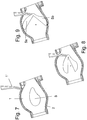
- FIGS. 7 to 9 a non-inventive example of an air duct 1 is shown, wherein the shape of the air duct 1 and the shape of the flow guide 5 correspond to those of the fourth embodiment, but the function is different - apart from the Arrangement and the silencing function in normal operation, the in Fig. 7 is shown - much of that of the example described above.
- the flow-guiding element 5 is formed by two parts 5a and 5b, the subdivision extending along the central longitudinal axis of the air duct 1.
- the two parts 5a and 5b are connected together downstream of the air by means of a hinge, which also defines the pivot axis of the parts 5a and 5b.
- the in Fig. 7 is shown, the two parts 5a and 5b respectively pivot outwardly in the direction of the wall 2 of the air duct 1, until they, as in Fig. 9 represented, in its other end position in abutment against the wall 2 reach.
- the outlet side of the air duct 1 is completely shut off.
- the flow guide 5 also serves the air distribution, via a snorkel-like line 1 ', which is inserted from the outside into the air duct 1, air are removed from the wedge-shaped area air upstream of the fully or partially opened flow guide 5 from the air duct 1 can.
- the insertion opening for the snorkel-like conduit 1 'in the wall 2 of the air duct 1 is in normal operation, i. in a pure flow through the air duct 1, sealed.
- the sound-absorbing material 3 of the wall 2 supports the sealing function.
- the line 1 By using the line 1 'results, for example, shortly before a vent, which is designed as a comfort jet with spot beam and diffused air outlet, an easy way to distribute the air to the two air channels (spot / diffuse).
- the snorkel-like line 1 ' can also be completely dispensed with, so that the flow-guiding element 5 merely serves to regulate the flow through the air duct 1.
- the air flow supports the opening of the flow guide 5.
- the snorkel-like line 1 ' can be dispensed with altogether, so that the flow-guiding element 5 merely serves to regulate the flow through the air duct 1, the direction of flow being from the other side, ie. coming from the right in the drawing.
- a flow can be provided according to the second variant of the fifth embodiment, in turn, a snorkel-like conduit is provided, which in this case air inlet side of the flow guide is inserted into the air duct.
- the arrangement of the pivot axis can also be provided on the air upstream side.
- FIGS. 10 and 11 show a longitudinal section through a non-inventive air duct, wherein in the air duct 1, an air guide element 5 is arranged.
- the cross section of the air duct 1 and the cross section of the air guide element correspond to those of the fifth embodiment, but the relative movement of the air guide elements to the air duct differs from each other.
- the spoiler 5 according to the sixth embodiment is in the air duct 1 in the present case rotatable by approximately 90 °. In the rotated position, the in Fig. 11 is indicated, the air guide 5 completely obstructs the air duct 1, ie it serves as a flap.
- stops 2 ' In the air duct 1, starting from the wall 2 on both sides stops 2 'are provided, against which the front and the rear end of the air guide 5 in the closed state.
- the stops 2 ' may be formed smaller or larger or omitted entirely.
- the stops can advantageously also be completely embedded in the sound-absorbing material of the wall, so that they have no influence on the air flow through the channel.
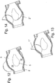
- FIGS. 12 to 14 is provided as a non-inventive example, a presently arranged in the air duct 1 flow guide 5, which divides the air duct 1 into two partial air channels 11 and 12.
- the cross section of the air duct 1 and the cross section of the air guide element correspond to those of the example according to Fig. 7-9 ,
- the air guide 5 is arranged rigidly in the air duct 1, but in the area of the air guide 5 in the wall 2 of the air duct 1 integrated a shut-off 2 "and a diverter 1" arranged.
- the diverting element 1 is designed in such a way that its one wall surface forms part of the wall 2 of the air duct 1 in the completely open state of the air duct 1.
- a second wall surface is provided at a distance from this wall surface of the diverting element 1", which in the closed state of the air duct 1
- the diverter 1 in a state in which the air flowing in the air duct 1, is discharged through the diverter 1 "in another air duct, abuts on the air guide 5, so that the discharge opening is arranged in the partial air channel 11.
- shut-off element 2 " which is inserted along a circular path from outside the air duct 1 into the air duct 1 until it comes with its front end in abutment against the air guide element 5, in the present case in the upstream region of the same.
- shut-off element 2 By the shut-off element 2 ", the air distribution between the air flow, which is discharged through the diversion element 1", and the air flow, which remains in the air duct 1, regulated.
- the air guide is also rotatably arranged in the air duct so that it can even meet the shut-off function in the second partial air channel, whereby the shut-off can be omitted.
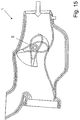
- Fig. 15 shows a fourth embodiment of a flow guide 5 in an air duct 1, wherein in the flow direction of the air behind the flow guide 5, a branching of the air channel 1 is provided.
- the branching air ducts lead the air to different outlets in the vehicle.
- Embodiment additionally the task of distributing the air to the two outlets.
- an adjusting movement ie in the present case a rotational movement of the flow guide 5
- the distribution of the amount of air is influenced differently on the two outlets and throttled overall. If the flow guide 5 is rotated further, that it completely closes the air channel, so no air gets to the two outlets.
- the Flow guide 5 is present in the form of an airfoil and consists of a sound-absorbing material.
- acoustic measures such as. Surfaces, bags, deposits, etc. may be provided from a sound-absorbing material.
- acoustic windows can be provided from sound-absorbing, teilschall trimric material.
- the air guide element may be provided with inflow and outflow side projections formed, which fulfill the same function, namely a good seal against the contact surface.
Landscapes
- Physics & Mathematics (AREA)
- Thermal Sciences (AREA)
- Engineering & Computer Science (AREA)
- Mechanical Engineering (AREA)
- Air-Conditioning For Vehicles (AREA)
- Duct Arrangements (AREA)
Description
- Die Erfindung betrifft einen schalldämpfenden Fluidkanal mit einem Strömungsleitelement gemäß dem Oberbegriff des Anspruches 1.
- Klimaanlagen für Kraftfahrzeuge weisen üblicherweise ein mehrteiliges, spritzgegossenes Gehäuse auf, das mit Luftkanälen verbunden ist, über welche die temperierte Luft dem Fahrzeuginnenraum zuführbar ist. Zur Vermeidung einer zu starken Geräuschentwicklung, die durch die durchströmende Luft oder von außerhalb des Gehäuseteils liegenden Schallquellen hervorgerufen und insbesondere an großwandigen Gehäuseteilen verstärkt wird, werden diese großflächigen Bereiche solcher Gehäuseteile mit einer Schaumstoffauflage versehen. Diese Schaumstoffauflage lässt sich in der Regel auf das Gehäuse nur nachträglich, d. h. nach Fertigstellung des Gehäuses, aufbringen, was jedoch aufwändig ist.
- Aus der
DE 36 39 138 C2 ist ein Gehäuse für eine Heizungs- oder Klimaanlage eines Kraftfahrzeugs bekannt, das mit Schaumstoff versehende Wandbereiche aufweist, welche aus einem schaumstoffummantelten Stützgerippe bestehen, wobei die Schaumstoffschicht nachträglich am Gehäuse anspritzbar ist. - Ferner ist aus der
DE 197 22 866 A1 ein Luftführungskanal einer Heizungs- oder Klimaanlage eines Kraftfahrzeugs bekannt, mit einer einem Gebläse zugeordneten Eingangsöffnung und einer Ausgangsöffnung, die dem weiteren Komponenten der Heizungs- oder Klimaanlage enthaltenden Gehäuse zugeordnet ist, wobei der Luftführungskanal mindestens eine Krümmung aufweist, so dass maximal nur zwischen einem kleinen Teilbereich der Eingangsöffnung und einem kleinen Teilbereich der Ausgangsöffnung eine lineare Verbindung möglich ist. Die Kanalwandung kann zumindest innenseitig mit schalldämpfendem Material ausgekleidet sein. - Die
DE 20 2006 014 683 offenbart einen verblockten Fluidkanal, jedoch keine wellenförmige Umlenkung, sondern eine Einschnürung. - Aus der
EP 1 630 486 A2 ist ferner eine Klappenanordnung mit einer um eine Drehachse verschwenkbaren Klappe bekannt, welche eine leicht S-förmig gekrümmte Oberfläche aufweist, wobei die Klappe einen steifen Klappengrundkörper hat, auf dessen Oberflächen ein geschäumtes Material vorgesehen ist, welches jedoch die Schmalseiten des Klappengrundkörpers freilässt. Das Vorsehen des geschäumten Materials an den Oberflächen dient hierbei dem Toleranzausgleich zum Luftkanal. - Die
WO 03/073016 A1 - Ferner sind zur Optimierung eines Strömungsverlaufs starr in einem Luftkanal angeordnete Strömungsleitelemente bekannt.
- Ebenfalls sind zur Regelung eines Fluidstroms Klappen oder Schieber bekannt, welche im Fluidkanal verschwenkbar oder verschiebbar angeordnet sind.
- Derartige Ausgestaltungen lassen noch Wünsche offen.
- Es ist Aufgabe der Erfindung, einen schalldämpfenden Fluidkanal mit einem Strömungsleitelement zur Verfügung zu stellen, der in seiner Funktion verbessert ist.
- Diese Aufgabe wird gelöst durch einen schalldämpfenden Fluidkanal mit einem Strömungsleitelement mit den Merkmalen des Anspruchs 1. Vorteilhafte Ausgestaltungen sind Gegenstand der Unteransprüche.
- Die Erfindung betrifft einen schalldämpfenden Fluidkanal mit einer Eintrittsöffnung aufweisend einen Eintrittsquerschnitt, einer Austrittsöffnung aufweisend einen Austrittsquerschnitt und mindestens einem im Fluidkanal zwischen dem Eintrittsquerschnitt und dem Austrittsquerschnitt angeordneten, schalldämpfenden Strömungsleitelement, wobei der Strömungsweg des Fluidkanals zwischen dem Eintrittsquerschnitt und dem Austrittsquerschnitt in mindestens einem Betriebszustand im Bereich des Strömungsleitelements vollständig versperrt ist, so dass das Fluid am Durchströmen gehindert ist. Das Strömungsleitelement ist hierbei derart im Fluidkanal angeordnet, dass es den Fluidstrom in zwei Teilströme unterteilt. Das Strömungsleitelement weist vorzugsweise einen profilierten Querschnitt mit mindestens einer gekrümmt in Strömungsrichtung verlaufenden Fläche auf. Das Strömungsleitelement kann hierbei beispielsweise kreisförmig, oval, elliptisch oder stromlinienförmig ausgebildet sein, besonders bevorzugt sind jedoch asymmetrische Querschnitte, insbesondere bevorzugt ist ein tropfentragflügelförmiger Querschnitt oder der Querschnitt ist stromlinienförmig profiliert. Durch eine Integration der Funktionen Schallabsorbierung und Versperrung kann der Bauraumbedarf verringert werden, insbesondere kann eine zusätzliche Klappe ganz entfallen.
- Bevorzugt ist das Strömungsleitelement durch schallabsorbierendes Material gebildet oder zumindest teilweise von schallabsorbierendem Material umgeben. Eine entsprechende Ausgestaltung unterstützt das Verhindern einer direkten Durchschallung des Fluidkanals. Hierbei ist am Strömungsleitelement oder der Wand des Fluidkanals keine geräuscherzeugende Anschlagkante erforderlich. Ferner ist eine Minimierung von Pfeif- und Zischgeräuschen im nahezu geschlossenen Zustand des Strömungsleitelements möglich.
- Vorzugsweise ist in zumindest einem Bereich, welcher durch schallabsorbierendes Material gebildet ist, eine Dämmwand angeordnet. Die Dämmwand kann im Strömungsleitelement ausgebildet sein, wobei sie auch tragende Funktionen für das schallabsorbierende Material übernehmen kann.
- Das Strömungsleitelement ist innerhalb des Fluidkanals bewegbar. Hierbei dient das Strömungsleitelement, ggf. mit anderen Elementen, im versperrten Zustand des Fluidkanals als Sperre. Dabei kann der Fluidstrom durch den Fluidkanal vollständig gesperrt oder in einen anderen Fluidkanal umgeleitet sein. Besonders bevorzugt schneidet oder berührt auch im vollständig geöffneten Zustand jede gerade Verbindung zwischen der Eintrittsöffnung zum erweiterten Bereich und der Austrittsöffnung aus dem erweiterten Bereich das Strömungsleitelement oder eines der Strömungsleitelemente, so dass eine direkte Durchschallung verhindert ist.
- Für eine ausreichende Behinderung einer direkten Durchschallung des Fluidkanals ist es jedoch ausreichend, wenn die Projektion des Strömungsleitelements auf die Eintrittsöffnung der Bedingung genügt:

- Bevorzugt entspricht die Summe der Flächen der Projektionen der Teilfluidkanäle auf die Eintrittsöffnung der Fläche der Eintrittsöffnung, jedoch kann die Summe der Flächen der Projektionen der Teilfluidkanäle FT in Einzelfällen auch der Bedingung 0,9 x FE < FT oder ggf. sogar 0,75 x FE < FT für eine ausreichende Funktion des Strömungsleitelements genügen.
- Besonders bevorzugt ist das Strömungsleitelement quer zur normalen Strömungsrichtung des Fluids verschiebbar, um das Strömungsprofil zu beeinflussen. Hierbei ist das Strömungsleitelement bevorzugt um 1/4 x FT verschiebbar ausgebildet, wobei FT die Summe der Flächen der Projektionen der Teilfluidkanäle ist.
- Ggf. auch in Verbindung mit einer linearen Verschiebbarkeit ist das Strömungsleitelement um eine Drehachse im Fluidkanal verschwenkbar ausgebildet.
- Hierbei ist das Strömungsleitelement besonders bevorzugt derart ausgebildet, dass es in einer Stellung den Fluidkanal vollständig verschließt.
- Durch ein Verschwenken des Strömungsleitelements kann die Temperatur- und Luftverteilung am Austrittsquerschnitt oder beispielsweise zwischen verschiedenen Auslässen einer Klimaanlage variiert werden.
- Das Strömungsleitelement kann auch mehrteilig, insbesondere bevorzugt zweiteilig, ausgebildet sein, wobei zwei Teile des Strömungsleitelements relativ zueinander verschwenkbar sind. Durch ein Aufklappen kann der Fluidkanal vollständig durch das Strömungsleitelement verschlossen werden. Insbesondere bevorzugt sind die beiden Teile des Strömungsleitelements in entgegengesetzte Richtung verschwenkbar. Bei der Ausführung des Strömungsleitelements als teilbare Klappe ergibt sich ein homogeneres Geschwindigkeitsprofil hinter dem Strömungsleitelement im Vergleich zu einer herkömmlichen Klappe.
- In den Fluidkanal kann in Ergänzung eine Leitung einführbar sein, über welche das Fluid oder ein Teilstrom des Fluids in einen anderen Fluidkanal überführbar ist.
- Besonders bevorzugt ist ein Fluidkanal vorgesehen, mit einer Wand, die zumindest bereichsweise mit schallabsorbierendem Material umgeben oder aus schallabsorbierendem Material gebildet ist, und/oder die zumindest bereichsweise durch ein schalltransparentes Material gebildet ist. Der Fluidkanal weist einen gekrümmten Verlauf auf, so dass nur zwischen einem Teilbereich der Eingangsöffnung und einem kleinen Teilbereich der Ausgangsöffnung eine lineare Verbindung möglich ist. Hierbei ist im Fluidkanal mindestens ein Strömungsleitelement vorgesehen, welches den Fluidkanal in zwei Teilfluidkanäle unterteilt und zumindest mit einem Teilbereich in dem Bereich des Fluidkanals angeordnet ist, in welchem eine ansonsten lineare Verbindung zwischen der Eingangsöffnung und der Ausgangsöffnung möglich ist. Ferner können weitere Verblockungen in Wellenform vorgesehen sein. Das Strömungsleitelement in Verbindung mit der Ausgestaltung des Fluidkanals, d.h. dessen Wandverlaufs, kann eine direkte Durchschallung des Fluidkanals auf relativ einfache Weise verhindern.
- Durch die Verwendung eines Strömungsleitelements kann zudem das Geschwindigkeitsprofil trotz einer Umlenkung, insbesondere bevorzugt einer wellenartigen Umlenkung, homogenisiert werden, so dass das Strömungsleitelement neben der Schalldämpfungsfunktion eine Strömungsprofil-Vergleichmäßigungsfunktion aufweist. Hierbei wird der Fluidkanal durch das Strömungsleitelement in zwei Teilfluidkanäle unterteilt, welche gemäß einer besonders bevorzugten Ausgestaltung jeweils einen Düsenbereich und einen Diffusorbereich aufweisen. Durch die geeignete Ausgestaltung der Düsen- und Diffusorbereiche kann durch besagte Homogenisierung der Geschwindigkeitsverteilung am Austrittsquerschnitt auch die (maximale) Strömungsgeschwindigkeit verringert werden, wodurch sich der Gesamtdruckverlust der Klimaanlage verringert. Ebenso wird die Geräuschentwicklung an den Austrittsquerschnitten reduziert
- Der Fluidkanal ist derart ausgebildet, dass er eine Verblockung in Wellenform aufweist. Hierbei sind gemäß einer bevorzugten Ausgestaltung, der Eintrittsquerschnitt vor der Verblockung und der Austrittsquerschnitt nach der Verblockung miteinander fluchtend angeordnet.
- Das Strömungsleitelement kann auch einen Sensor aufnehmen, z.B. Temperatursensor, der beispielsweise im Außenbereich auf einer quer zum Fluidkanal verlaufenden harten Rippe montiert ist, wobei der elektrische Anschluss über die Drehachse des Dämpfungselements nach außen verlegt ist. Weiterhin ist es möglich, das Strömungsleitelement mit einem Beduftungssystem oder einem System zur Verbesserung der Luftgüte auszustatten.
- Beim Fluidkanal handelt es sich vorzugsweise um den Luftkanal, über welchen der Mitteldüse eines Fahrzeuginnenraums Luft in denselben zugeführt wird. Entsprechende Ausgestaltungen sind jedoch auch für beliebige andere Fluidkanäle möglich, also bspw. für einen Luftkanal zum Fondbereich oder zu den Seitendüsen. Die "Welle" im Fluidkanal erhöht zwar leicht den erforderlichen Bauraum, verbessert aber die aerodynamische Funktion des Fluidkanales und verhindert oder verringert die Weiterleitung von Geräuschen, wie beispielsweise Gebläse- oder Strömungsgeräusche aus dem Inneren des Klimaanlagengehäuses.
- Eine besonders bevorzugte Anwendungsform eines derartigen Luftkanals ist die Verwendung als Schalldämpfer, jedoch sind auch andere Anwendungen möglich.
- Vorteilhaft ist, dass im Strömungsleitelement ein Sensor angeordnet ist.
- Vorteilhaft ist, dass im Strömungsleitelement ein Beduftungssystem oder ein System zur Verbesserung der Luftgüte angeordnet ist.
- Im Folgenden wird die Erfindung anhand mehrerer Ausführungsbeispiele mit Varianten, teilweise unter Bezugnahme auf die Zeichnung, im Einzelnen erläutert. Es zeigen:
- Fig. 1
- einen Längsschnitt durch einen Luftkanal gemäß dem ersten Ausführungsbeispiel,
- Fig. 2
- einen Längsschnitt durch einen Luftkanal gemäß dem zweiten Ausführungsbeispiel,
- Fig. 3
- einen Längsschnitt durch einen Luftkanal gemäß dem dritten Ausführungsbeispiel mit durch Pfeile angedeutetem Strömungsprofil am Luftein- und -austritt, und
- Fig. 4
- eine
Fig. 3 entsprechende Darstellung zur Verdeutlichung der Abmessungen, auf welche Bezug genommen wird. - Fig. 5
- einen Längsschnitt durch einen nicht erfindungsgemäßen Luftkanal in geöffneter Schieberstellung,
- Fig. 6
- einen Längsschnitt durch den Luftkanal von
Fig. 5 in geschlossener Schieberstellung, - Fig. 7
- einen Längsschnitt durch einen nicht erfindungsgemäßen Luftkanal in geöffneter Stellung,
- Fig. 8
- einen Längsschnitt durch den Luftkanal von
Fig. 7 in teilweise geschlossener Stellung, - Fig. 9
- einen Längsschnitt durch den Luftkanal von
Fig. 7 in geschlossener Stellung, - Fig. 10
- einen Längsschnitt durch einen nicht erfindungsgemäßen Luftkanal in geöffneter Stellung,
- Fig. 11
- einen Längsschnitt durch den Luftkanal von
Fig. 10 in geschlossener Stellung, - Fig. 12
- einen Längsschnitt durch einen nicht erfindungsgemäßen Luftkanal in geöffneter Stellung,
- Fig. 13
- einen Längsschnitt durch den Luftkanal von
Fig. 12 in teilweise geschlossener Stellung, - Fig. 14
- einen Längsschnitt durch den Luftkanal von
Fig. 12 in geschlossener Stellung, und - Fig. 15
- einen Längsschnitt durch einen Luftkanal gemäß dem vierten Ausführungsbeispiel mit Darstellung des Strömungsleitelements in geöffneter und geschlossener Stellung.
-
Fig. 1 zeigt einen Längsschnitt durch einen Fluidkanal, vorliegend einen Luftkanal 1, der mit einem Klimaanlagengehäuse (nicht dargestellt) verbunden ist, und über den temperierte Luft dem Fahrzeuginnenraum zuführbar ist. Der Pfeil zeigt hierbei die Strömungsrichtung der Luft an. Der Luftkanal 1 wird vorliegend durch eine Wand 2 gebildet, welche aus einem Kunststoffmaterial spritzgegossen ist. - Der Luftkanal 1 weist im dargestellten Bereich eine leichte Richtungs- und Querschnittsveränderung auf, wobei im in
Fig. 1 oben dargestellten Bereich die Wand 2 wellenartig ausgebildet ist (vorliegend ist ein Wellental vorgesehen) und von außen mit Elementen aus schallabsorbierenden Material 3, vorliegend einem akustischen Schaum, versehen ist. Zwei benachbarte Elemente sind vorliegend durch eine Dämmwand 4 getrennt. Die Elemente sind vorliegend derart geformt, dass die Welle der Wand 2 aufgefüllt ist, so dass sich unter Einbeziehung der Dämmwand 4 eine Art Ebene ergibt. Zur akustischen Anbindung der Wand 2 an die Elemente aus schallabsorbierenden Material 3 ist die Wand 2 zumindest in Teilbereichen unterbrochen, so dass sie dort nur noch als Kraft aufnehmende Rippenstruktur ausgebildet ist. - In dem in
Fig. 1 unten dargestellten Bereich, in welchem die Wand 2 nach außen gekrümmt ist, ist dagegen ein Element aus schallabsorbierendem Material 3 angebracht, welches eine im Wesentlichen konstante Dicke aufweist. - Auch auf der Innenseite der Wände 2 sind dünn ausgebildete Elemente aus schallabsorbierendem Material 3 aufgebracht, wobei die Elemente vorliegend aus dem gleichen Material gefertigt sind.
- Im Innenraum des Luftkanals 1 sind ferner zwei unterschiedliche Strömungsleitelemente 5 und 6 angeordnet, wobei das erste Strömungsleitelement 5 einen stromlinienförmig profilierten Querschnitt und das zweite Strömungsleitelement 6 einen leicht entsprechend dem Luftkanalverlauf gekrümmten Verlauf mit konstanter Dicke auf. Das erste Strömungsleitelement 5 weist eine Dämmwand 7, welche als tragende Struktur dient, auf, welche eine konstante Dicke hat und in ihrer Erstreckung im Wesentlichen senkrecht zur Wand 2 des Luftkanals 1 angeordnet ist. Alternativ ist auch eine Ausrichtung der Dämmwand in Längsrichtung des Strömungsleitelements möglich.
- An der Dämmwand 7 sind zwei profilierte Elemente aus schallabsorbierendem Material 3 angebracht, so dass sich insgesamt die besagte stromlinienförmige Gestalt des ersten Strömungsleitelements 5 ergibt.
- Das erste Strömungsleitelement 5 ist vorliegend etwas nach oben versetzt im Luftkanal 1 angeordnet, wobei es um eine Drehachse verschwenkbar ist, so dass es bei einer um ca. 90° gedrehten Stellung den Luftkanal 1 vollständig verschließt, wobei die von einander entferntesten Bereiche des Luftleitelements 5 vorliegend an der Wand 2 des Luftkanals 1 dicht anliegen. Die Dichtfunktion wird durch die Elastizität des schallabsorbierenden Materials 3 des Strömungsleitelements 5 sowie des schallabsorbierenden Materials 3 der Wand 2 unterstützt. Hierbei ist das schallabsorbierende Material 3 derart an der Dämmwand 7 angebracht, dass das schallabsorbierende Material 3 in Richtung parallel zur Drehachse leicht überstehend ausgebildet ist, wodurch ein seitliches Vorbeiströmen von Luft am Strömungsleitelement 5 verhindert wird. Bei einer Bewegung reiben die Enden des schallabsorbierenden Materials 3 an der Wand 2, was im Wesentlichen geräuschfrei erfolgt. Eine ähnliche Abdichtung kann an den Seitenwänden senkrecht zur Drehachse erfolgen, wobei hier alternativ auch Anschlagkanten verwendet werden können.
- Das zweite Strömungsleitelement 6 ist etwas nach unten versetzt im Luftkanal 1 angeordnet, wobei es - in Luftströmungsrichtung gesehen - kurz nach dem Ende des ersten Strömungsleitelements 5 anfängt. Das zweite Strömungsleitelement 6 ist vorliegend vollständig von einer dünnen Schicht aus schallabsorbierendem Material 3 umgeben.
- Insgesamt ergeben sich so im Normalbetrieb, d.h. bei maximalem Strömungsquerschnitt, ein Ein- und ein Austrittsquerschnitt, die auf Grund der Einbauten (erstes und zweites Strömungsleitelement) nicht auf direktem Wege mit einer linearen Verbindung miteinander verbindbar sind.
- Vorliegend erfolgt die Anordnung der Elemente aus schallabsorbierendem Material 3 derart, dass keine direkte Durchschallung des Luftkanals 1 möglich ist, d.h. die Elemente sind nicht nur um den Luftkanal 1 herum sondern insbesondere auch im Weg der Schallausbreitung, d.h. der linearen Verbindung zwischen Eintrittsquerschnitt und Austrittsquerschnitt angeordnet (z.B. in Gestalt der Strömungsleitelemente 5, 6 und der Welle). Auf Grund ihrer Funktion wird auf den nach unten in den Strömungsweg ragenden Bereich auch als Verblockung Bezug genommen.
- Gemäß einer nicht in der Zeichnung dargestellten Variante des ersten Ausführungsbeispiels ist die Wand in Richtung Innenraum des Luftkanals perforiert ausgebildet. Das schallabsorbierende Material wird von außen her auf diese Wand gelegt, so dass die Wand durchschallt werden kann und ein teil des Schalls nach außen abgegeben und somit nicht in Strömungsrichtung der Luft weitergeleitet wird.
- Die Wand kann auch rahmenartig ausgebildet und zumindest in ihren offenen Bereichen durch schallabsorbierendes Material ausgefüllt sein.
- Gemäß einer weiteren Variante ist zur perforierten Wand mit schallabsorbierendem Material eine zweite durchgehend ausgebildete Wand vorgesehen, welche das schallabsorbierende Material von außen her abgedeckt, so dass das schallabsorbierende Material zwischen zwei Wänden angeordnet ist, wovon die innere Wand gut schalldurchlässig ausgebildet ist. In diesem Fall wird eine Durchschallung des schallabsorbierenden Materials verhindert und zudem eine Einstreuung von Schallquellen aus der Umgebung des Luftkanals verhindert.
- Das im Folgenden beschriebene, zweite Ausführungsbeispiel unterscheidet sich vom ersten Ausführungsbeispiel nur in der Ausgestaltung der Wand 2 des Luftkanals 1, so dass für gleiche oder gleichwirkende Elemente im Folgenden dieselben Bezugszeichen verwendet werden. Auch in diesem Fall ist das erste Strömungsleitelement 5 um eine Drehachse verschwenkbar, so dass es den Luftkanal 1 vollständig verschließen kann.
- Die Wand 2 des Luftkanals 1 wird vorliegend in den in
Fig. 2 schraffiert dargestellten Bereichen, also in den Bereichen auf der Krümmungsinnen- und -außenseite des Luftkanals 1, die gemäß dem ersten Ausführungsbeispiel von innen und außen her mit schallabsorbierendem Material 3 bedeckt sind, durch ein schalltransparentes Material 13 gebildet. Als schallabsorbierendes und teilweise schalltransparentes Material dient vorliegend ein Vlies mit einer Materialdicke von ca. (1 bis 3 mm) +/- 1 mm. Gemäß dem zweiten Ausführungsbeispiel entfällt ferner die Dämmwand 4, welche gemäß dem ersten Ausführungsbeispiel auf der Außenseite des Luftkanals 1 ausgebildet und zwischen zwei Elementen aus schallabsorbierendem Material angeordnet ist. - Zweck des zweiten Strömungsleitelements 6 bei in beiden vorstehend beschriebenen Ausführungsbeispielen ist eine vollständige Verblockung des Strömungsquerschnitts, welche vorliegend nicht ausschließlich durch das erste Strömungsleitelement 5 möglich ist.
- Gemäß dem dritten, in
Fig. 3 und4 dargestellten Ausführungsbeispiel ist lediglich ein einziges Strömungsleitelement im Luftkanal 1 angeordnet, welches in seiner Gestalt und seinem Aufbau, auch wenn nicht explizit dargestellt, im Wesentlichen dem ersten Strömungsleitelement 5 der vorigen Ausführungsbeispiele entspricht, weshalb dieses Strömungsleitelement ebenfalls mit dem Bezugszeichen 5 versehen ist. Auch dieses Strömungsleitelement 5 ist um eine Drehachse verschwenkbar im Luftkanal 1 angeordnet, so dass es den freien Strömungsquerschnitt vollständig verschließen kann. - Auch der Luftkanal 1 gemäß dem dritten Ausführungsbeispiel weist eine wellenartige Umlenkung auf. Die Umlenkung weist eine Länge L auf, wobei die maximale Tiefe der Verblockung A2 vorliegend auch dem Abstand des Strömungsleitelements 5 von der entsprechenden Wand 2 entspricht (siehe
Fig. 4 ). Die genaue Position des Strömungsleitelements 5 und die maximale Tiefe der Verblockung A2 ergibt sich aus den Eintrittsrandbedingungen, d.h. aus V(y). Im vorliegenden Fall ist die Eintrittsgeschwindigkeit in y-Richtung im oben dargestellten Bereich höher als im unten dargestellten Bereich. - Die Höhe des Strömungsleitelements 5 ist auch mit A1 bezeichnet. Die Eintrittshöhe in den auf der Seite der Verblockung angeordneten, ersten Teilluftkanal 11 ist in der Zeichnung mit A3 bezeichnet. Durch das Strömungsleitelement 5 ergibt sich in beiden anströmseitigen Teilluftkanälen 11 bzw. 12 eine Düsenfunktion (in
Fig. 3 bezeichnet mit Düse 1 bzw. Düse 2) und in den ausströmseitigen Teilluftkanälen eine Diffusorfunktion (inFig. 3 bezeichnet mit Diffusor 1 bzw. Diffusor 2), wobei der engste Querschnitt der Düse 1 mit E1, der engste Querschnitt der Düse 2 mit E2, der Austritt aus dem Diffusor 1 mit D1 und der Austritt aus dem Diffusor 2 mit D2 bezeichnet sind. Der Querschnitt in Strömungsrichtung nach dem Strömungsleitelement 5 bleibt im Wesentlichen konstant, wie inFig. 4 mit D1+D2 angedeutet. Ferner sei darauf hingewiesen, dass der engste Querschnitt der Düse jeweils dem Eintritt in den entsprechenden Diffusor entspricht. - Folgende Verhältnisse haben sich als vorteilhaft herausgestellt:

- Insbesondere für den Schalldämpfer gemäß dem vorliegenden Ausführungsbeispiel sind Verhältnisse für A2/L von 0,15 bis 0,35, und ganz besonders bevorzugt 0,15 bis 0,3 geeignet.
- Die Tiefe der Verblockung A2 ist abhängig von der Geschwindigkeit V(y), d.h. vom Eintrittsprofil. Bevorzugt ist die Eintrittshöhe in den ersten Teilluftkanal 11 kleinergleich der Höhe der Verblockung, d.h. es gilt bevorzugt:

- Ferner sind folgende Verhältnisse für den dargestellten Schalldämpfer geeignet:


- Allgemein sind die folgenden Verhältnisse sinnvoll:


- Um die Luftverteilung bis zum Kanalaustritt zu vergleichmäßigen, wird beim vorliegenden Eintrittsströmungsprofil die Strömung im Teilluftkanal 11 etwas stärker gedrosselt als im Teilkanal 12, indem E1 kleiner ausgeführt wird als E2. Somit ist das Verhältnis E1/E2, in erster Linie, abhängig von V(y). Durch eine Abmessungswahl entsprechend den vorstehenden Angaben, ergibt sich vorliegend ein sehr gutes Strömungsprofil verbunden mit einer geringen Schalldurchlässigkeit in Strömungsrichtung der Luft.
- In sämtlichen zuvor beschriebenen Ausführungsbeispielen kann der Fluid- oder Luftkanal 1 als Einsatz ausgebildet sein, welcher an Stelle eines herkömmlichen Bereichs in das Fluidkanalsystem, beispielsweise einer Fahrzeug-Klimaanlage, eingesetzt werden kann. Die Anbringung derartiger Fluid- oder Luftkanäle in einem Luftkanalsystem erfolgt vorzugsweise mit geeigneten, formschlüssigen Befestigung zwischen den Bauteilen, wobei akustisch wirksame Materialien vorgesehen sind, die eine störungsfreie Überströmung der Fügestellen ermöglichen.
- Im Folgenden wird unter Bezugnahme auf die
Figuren 5 und 6 ein nicht erfindungsgemäßes Beispiel näher erläutert.Figuren 5 und 6 zeigt einen Längsschnitt durch einen vorliegend getrennt ausgebildeten Abschnitt eines Luftkanals 1, der mit einem Klimaanlagengehäuse (nicht dargestellt) verbunden ist, und über den temperierte Luft dem Fahrzeuginnenraum zuführbar ist. Die Pfeile inFig. 5 zeigen hierbei die Strömungsrichtung der Luft an. Der Luftkanal 1 wird vorliegend durch eine Wand 2 gebildet, deren Struktur aus einem Kunststoffmaterial spritzgegossen ist. Die Wand 2 oder zumindest große Bereiche der Wand 2, wie auch die Oberfläche des Strömungsleitelements 5 sind durch schallabsorbierendes Material gebildet. Das Strömungsleitelement kann alternativ auch vollständig oder in Teilen durch schallabsorbierendes Material gebildet sein. - Das Strömungsleitelement 5 ist in einer Erweiterung des Luftkanals 1 angeordnet, wobei es den Luftkanal 1 in zwei Teilluftkanäle 11, 12 unterteilt. Das Strömungsleitelement 5 ist tropfenförmig, mit asymmetrischer tragflügelförmiger Gestalt ausgebildet. Es ist mittels einer Verstellvorrichtung in Längsrichtung des Luftkanals 1 verschiebbar, vorliegend mittels eines Zahnrads und einer Zahnstange, die im Inneren des Strömungsleitelements 5 angeordnet sind, wie in der Zeichnung schematisch angedeutet, so dass es im Bereich mit seinem maximalen Querschnitt (Höhe A1) den Eintrittsquerschnitt (Höhe B1) des Luftkanals 1 vollständig versperren kann (siehe
Fig. 6 ). - Bei in Längsrichtung verschiebbaren Strömungsleitelementen 5 mit Luftregelfunktion gilt, dass die maximale Höhe A1 des Strömungsleitelements 5 größer oder gleich der minimalen Höhe B1 des Luftkanals 1 im Eintrittsquerschnitt (oder gemäß einer nicht in der Zeichnung dargestellten Variante des vierten Ausführungsbeispiel bei einer Verschiebbarkeit zum Verschließen des Luftkanals 1 in Richtung Luftaustritt der minimalen Höhe des Luftkanals 1 im Austrittsquerschnitt) ist.
- Das Strömungsleitelement 5 hat neben der Luftregelfunktion auch die Funktion der Strömungsvergleichmäßigung, d.h. ein ungleichmäßiges Strömungsprofil am Eintrittsquerschnitt wird durch die unterschiedlichen Strömungswege um das Strömungsleitelement 5 vergleichmäßigt. Bei entsprechender Anströmung kann jedoch auch ein spiegelbildlich ausgebildetes Strömungsleitelement verwendet werden.
- In den
Figuren 7 bis 9 ist ein nicht erfindungsgemäßes Beispiel eines Luftkanals 1 dargestellt, wobei die Form des Luftkanals 1 sowie die Form des Strömungsleitelements 5 denjenigen des vierten Ausführungsbeispiels entsprechen, jedoch unterscheidet sich die Funktion - abgesehen von der Anordnung und der Schalldämpffunktion im Normalbetrieb, die inFig. 7 dargestellt ist - wesentlich von der des zuvor beschriebenen Beispiels. - Das Strömungsleitelement 5 ist vorliegend durch zwei Teile 5a und 5b gebildet, wobei die Unterteilung entlang der Mittellängsachse des Luftkanals 1 verläuft. Die beiden Teile 5a und 5b sind luftabströmseitig mittels eines Scharniers miteinander verbunden, welches auch die Schwenkachse der Teile 5a und 5b definiert. Ausgehend vom aneinander anliegenden Zustand, der in
Fig. 7 dargestellt ist, schwenken die beiden Teile 5a und 5b jeweils nach außen in Richtung Wand 2 des Luftkanals 1 weg, bis sie, wie inFig. 9 dargestellt, in ihrer anderen Endstellung in Anlage an die Wand 2 gelangen. In der inFig. 9 dargestellten Anordnung wird die Austrittsseite des Luftkanals 1 vollständig abgesperrt. - Gemäß dem Beispiel dient jedoch das Strömungsleitelement 5 zusätzlich der Luftverteilung, wobei über eine schnorchelartige Leitung 1', welche von außen her in den Luftkanal 1 einführbar ist, Luft aus dem keilförmigen Bereich luftanströmseitig des ganz oder teilweise geöffneten Strömungsleitelements 5 aus dem Luftkanal 1 abgeführt werden kann. Die Einführöffnung für die schnorchelartige Leitung 1' in der Wand 2 des Luftkanals 1 ist im Normalbetrieb, d.h. bei einer reinen Durchströmung des Luftkanals 1, abgedichtet. Hierbei unterstützt das schallabsorbierende Material 3 der Wand 2 die Dichtfunktion.
- Durch die Verwendung der Leitung 1' ergibt sich beispielsweise kurz vor einem Ausströmer, welcher als Komfortdüse mit Spotstrahl und diffusem Luftaustritt ausgebildet ist, eine einfache Möglichkeit, die Luft auf die beiden Luftkanäle (spot/diffus) zu verteilen.
- Die schnorchelartige Leitung 1' kann gemäß einer Variante des Beispiels auch ganz entfallen, so dass das Strömungsleitelement 5 lediglich der Durchflussregelung durch den Luftkanal 1 dient. Hierbei unterstützt die Luftströmung das Öffnen des Strömungsleitelements 5.
- Gemäß einer zweiten Variante des Beispiels kann wiederum die schnorchelartige Leitung 1' ganz entfallen, so dass das Strömungsleitelement 5 lediglich der Durchflussregelung durch den Luftkanal 1 dient, wobei die Strömungsrichtung von der anderen Seite her erfolgt, d.h. in der Zeichnung von rechts kommend.
- Gemäß einer weiteren Variante des Beispiels kann eine Durchströmung entsprechend der zweiten Variante des fünften Ausführungsbeispiels vorgesehen sein, wobei wiederum eine schnorchelartige Leitung vorgesehen ist, welche in diesem Fall luftanströmseitig des Strömungsleitelements in den Luftkanal einführbar ist. Beim vorstehend beschriebenen fünften Ausführungsbeispiel und dessen Varianten kann die Anordnung der Schwenkachse auch luftanströmseitig vorgesehen sein.
Figuren 10 und 11 zeigen einen Längsschnitt durch einen nicht erfindungsgemäßen Luftkanal, wobei im Luftkanal 1 ein Luftleitelement 5 angeordnet ist. Der Querschnitt des Luftkanals 1 sowie der Querschnitt des Luftleitelements entsprechen denjenigen des fünften Ausführungsbeispiels, jedoch unterscheidet sich die Relativbewegung der Luftleitelemente zum Luftkanal voneinander. Das Luftleitelement 5 gemäß dem sechsten Ausführungsbeispiel ist im Luftkanal 1 vorliegend um ca. 90° verdrehbar. In der gedrehten Stellung, die inFig. 11 angedeutet ist, versperrt das Luftleitelement 5 den Luftkanal 1 vollständig, d.h. es dient als Klappe. - Dahingegen dient es in der geöffneten Stellung von
Fig. 10 der Vergleichmäßigung der Strömungsgeschwindigkeit über den Querschnitt. - Im Luftkanal 1 sind, ausgehend von der Wand 2 beidseitig Anschläge 2' vorgesehen, an welchen das vordere und das hintere Ende des Luftleitelements 5 im geschlossenen Zustand anliegen. Je nach Abmessung des Luftleitelements 5 und des Luftkanals 1 können die Anschläge 2' kleiner oder größer ausgebildet sein oder ganz entfallen. Die Anschläge können vorteilhafterweise auch vollständig in das schallabsorbierende Material der Wand eingebettet sein, so dass sie keinen Einfluss auf die Luftströmung durch den Kanal haben.
- In den
Figuren 12 bis 14 ist als nicht erfindungsgemäßes Beispiel ein vorliegend starr im Luftkanal 1 angeordnetes Strömungsleitelement 5 vorgesehen, welches den Luftkanal 1 in zwei Teilluftkanäle 11 und 12 unterteilt. Der Querschnitt des Luftkanals 1 sowie der Querschnitt des Luftleitelements entsprechen denjenigen des Beispiels nachFig. 7-9 . Im Unterschied zu den vorigen Beispielen ist das Luftleitelement 5 starr im Luftkanal 1 angeordnet, jedoch sind im Bereich des Luftleitelements 5 in die Wand 2 des Luftkanals 1 integriert ein Absperrelement 2" sowie ein Ausleitelement 1" angeordnet. - Das Ausleitelement 1" ist derart ausgebildet, dass seine eine Wandfläche im vollständig geöffneten Zustand des Luftkanals 1 einen Teil der Wand 2 des Luftkanals 1 bildet. Eine zweite Wandfläche ist beabstandet von dieser Wandfläche des Ausleitelements 1" vorgesehen, welche im geschlossenen Zustand des Luftkanals 1, also in einem Zustand, in welchem die Luft, welche im Luftkanal 1 strömt, durch das Ausleitelement 1" in einen anderen Luftkanal abgeleitet wird, am Luftleitelement 5 anliegt, so dass die Ausleitöffnung im Teilluftkanal 11 angeordnet ist. Der Strömungsweg durch den zweiten Teilluftkanal 12 ist durch das Absperrelement 2" versperrt, welches entlang einer Kreisbahn von außerhalb des Luftkanals 1 in den Luftkanal 1 eingeschoben wird, bis es mit seinem vorderen Ende in Anlage an das Luftleitelement 5, vorliegend im anströmseitigen Bereich desselben, gelangt.
- Durch das Absperrelement 2" lässt sich die Luftverteilung zwischen dem Luftstrom, der durch das Ausleitelement 1" ausgeleitet wird, und dem Luftstrom, der im Luftkanal 1 verbleibt, geregelt.
- Gemäß einer Variante des Beispiels ist das Luftleitelement zudem noch derart verdrehbar im Luftkanal angeordnet, so dass es selbst die Absperrfunktion im zweiten Teilluftkanal erfüllen kann, wodurch das Absperrelement entfallen kann. Durch die Anlage des Ausleitelements im kreisförmig ausgebildeten Bereich des Luftleitelements, in welchem zudem mittig die Drehachse angeordnet ist, kann eine dichte Anlage über den gesamten Drehbereich des Luftleitelements ermöglicht werden.
-
Fig. 15 zeigt ein viertes Ausführungsbeispiel eines Strömungsleitelements 5 in einem Luftkanal 1, wobei in Strömungsrichtung der Luft hinter dem Strömungsleitelement 5 eine Verzweigung des Luftkanals 1 vorgesehen ist. Die abzweigenden Luftkanäle führen die Luft zu unterschiedlichen Austritten im Fahrzeug. Im Unterschied zu den zuvor beschriebenen Beispielen hat das Strömungsleitelement 5 gemäß dem vierten - Ausführungsbeispiel zusätzlich die Aufgabe, die Luft auf die beiden Austritte zu verteilten. Durch eine Stellbewegung, d.h. vorliegend eine Drehbewegung, des Strömungsleitelements 5 wird die Verteilung der Luftmenge auf die beiden Austritte unterschiedlich beeinflusst und insgesamt gedrosselt. Wird das Strömungsleitelement 5 weiter gedreht, dass es den Luftkanal vollständig verschließt, so gelangt keine Luft zu den beiden Austritten. Das Strömungsleitelement 5 ist vorliegend tragflächenförmig ausgebildet und besteht aus einem schallabsorbierenden Material.
- Zusätzlich können im Luftkanal weitere akustische Maßnahmen, wie z.B. Oberflächen, Taschen, Einlagen, usw. aus einem schallabsorbierenden Material vorgesehen sein. Ebenso können akustische Fenster aus schallabsorbierendem, teilschalldurchlässigem Material vorgesehen sein.
- Anstelle von Anschlägen an den Wänden kann auch das Luftleitelement mit anström- und abströmseitig ausgebildeten Vorsprüngen versehen sein, welche die gleiche Funktion, nämlich ein gutes Abdichten gegenüber der Anlagefläche, erfüllen.
Claims (12)
- Schalldämpfender Fluidkanal mit einer Eintrittsöffnung aufweisend einen Eintrittsquerschnitt (A), einer Austrittsöffnung aufweisend einen Austrittsquerschnitt und mit einer wellenartigen Umlenkung, und mindestens einem im Fluidkanal (1) zwischen dem Eintrittsquerschnitt (A) und dem Austrittsquerschnitt angeordneten, schalldämpfenden und einem um eine Drehachse im Luftkanal (1) verschwenkbaren Strömungsleitelement (5), wobei der Strömungsweg des Fluidkanals (1) zwischen dem Eintrittsquerschnitt (A) und dem Austrittsquerschnitt in mindestens einem Betriebszustand im Bereich des Strömungsleitelements (5) vollständig versperrt ist, so dass das Fluid am Durchströmen gehindert ist, wobei eine Verblockung von einer Seite des Fluidkanals (1) und eine Erweiterung in Richtung der anderen Seite des Fluidkanals (1) vorgesehen ist, wobei der Eintrittsquerschnitt vor der Verblockung und Erweiterung und der Austrittsquerschnitt nach der Verblockung und Erweiterung miteinander fluchtend angeordnet sind.
- Fluidkanal nach Anspruch 1, dadurch gekennzeichnet, dass das Strömungsleitelement (5) zumindest bereichsweise durch ein schallabsorbierendes Material (3) gebildet ist.
- Fluidkanal nach einem der vorhergehenden Ansprüche, dadurch gekennzeichnet, dass das Strömungsleitelement (5) linear verschiebbar ist.
- Fluidkanal nach einem der vorhergehenden Ansprüche, dadurch gekennzeichnet, dass das Strömungsleitelement (5) mehrteilig ausgebildet ist, wobei mindestens zwei Teile des Strömungsleitelements (5) relativ zueinander verschwenkbar sind.
- Fluidkanal nach Anspruch 4, dadurch gekennzeichnet, dass die beiden Teile des Strömungsleitelements (5) in entgegengesetzte Richtung verschwenkbar sind.
- Fluidkanal nach Anspruch 4 oder 5, dadurch gekennzeichnet, dass in den Fluidkanal (1) eine Leitung eingeführt ist, über welche das Fluid oder ein Teilstrom des Fluids in einen anderen Fluidkanal überführt ist.
- Fluidkanal nach einem der vorhergehenden Ansprüche, dadurch gekennzeichnet, dass zumindest ein Teilkanal (11, 12) um das Strömungsleitelement (5) einen als Düse ausgebildeten Eintrittsbereich und einen als Diffusor ausgebildeten Austrittsbereich aufweist.
- Fluidkanal nach einem der vorhergehenden Ansprüche , dadurch gekennzeichnet, dass die Tiefe der Verblockung (A2) im Verhältnis zur Länge der Verblockung (L) im Bereich von 0,15 bis 0,35 liegt.
- Fluidkanal nach einem der vorhergehenden Ansprüche, dadurch gekennzeichnet, dass das Strömungsleitelement (5) den Fluidkanal (1) in zwei Teilfluidkanäle (11, 12) aufteilt, wobei die Geometrie der Teilfluidkanäle (11 und 12) dadurch bestimmt ist, dassder engste Querschnitt (E1) des ersten Teilfluidkanals (11), der benachbart der Verblockung verläuft, im Verhältnis zur Eintrittshöhe (A3) des Teilfluidkanals (11) im Bereich von 0,30 bis 0,95 liegt,das Verhältnis des engsten Querschnitts (E1) des ersten Teilfluidkanals (11) zum Austritt aus dem ersten Teilfluidkanal (11) im Bereich 0,65 bis 0,95 liegt, unddas Verhältnis des engsten Querschnitts (E2) des zweiten Teilfluidkanals (12) zum Austritt aus dem zweiten Teilfluidkanal (12) im Bereich 0,65 bis 0,95 liegt.
- Fluidkanal nach einem der vorhergehenden Ansprüche, dadurch gekennzeichnet, dass der Fluidkanal (1) einen zweiten Austrittsquerschnitt aufweist, wobei die Fluidverteilung auf die Austrittsquerschnitte durch das Strömungsleitelement (5) regelbar ist.
- Fluidkanal nach einem der vorhergehenden Ansprüche, dadurch gekennzeichnet, dass im Strömungsleitelement (5) ein Sensor angeordnet ist.
- Fluidkanal nach einem der vorhergehenden Ansprüche, dadurch gekennzeichnet, dass im Strömungsleitelement (5) ein Beduftungssystem oder ein System zur Verbesserung der Luftgüte angeordnet ist.
Applications Claiming Priority (2)
| Application Number | Priority Date | Filing Date | Title |
|---|---|---|---|
| DE102007062827A DE102007062827A1 (de) | 2007-12-21 | 2007-12-21 | Schalldämpfender Fluidkanal mit einem Strömungsleitelement |
| PCT/EP2008/009397 WO2009083064A1 (de) | 2007-12-21 | 2008-11-07 | Schalldämpfender fluidkanal mit einem strömungsleitelement |
Publications (2)
| Publication Number | Publication Date |
|---|---|
| EP2237979A1 EP2237979A1 (de) | 2010-10-13 |
| EP2237979B1 true EP2237979B1 (de) | 2016-01-27 |
Family
ID=40340488
Family Applications (2)
| Application Number | Title | Priority Date | Filing Date |
|---|---|---|---|
| EP08867541.8A Not-in-force EP2237979B1 (de) | 2007-12-21 | 2008-11-07 | Schalldämpfender fluidkanal mit einem strömungsleitelement |
| EP20080021606 Ceased EP2072297B1 (de) | 2007-12-21 | 2008-12-12 | Klappe, insbesondere für einen Luftkanal |
Family Applications After (1)
| Application Number | Title | Priority Date | Filing Date |
|---|---|---|---|
| EP20080021606 Ceased EP2072297B1 (de) | 2007-12-21 | 2008-12-12 | Klappe, insbesondere für einen Luftkanal |
Country Status (3)
| Country | Link |
|---|---|
| EP (2) | EP2237979B1 (de) |
| DE (1) | DE102007062827A1 (de) |
| WO (1) | WO2009083064A1 (de) |
Families Citing this family (6)
| Publication number | Priority date | Publication date | Assignee | Title |
|---|---|---|---|---|
| DE102012212805A1 (de) * | 2012-07-20 | 2014-01-23 | Behr Gmbh & Co. Kg | Klimaanlage mit einem Luftumlenkelement |
| DE102014217163B4 (de) | 2014-08-28 | 2025-03-06 | Mahle International Gmbh | Luftsteuereinrichtung mit Lagerstelle |
| US10144269B2 (en) | 2015-10-28 | 2018-12-04 | Ford Global Technologies, Llc | Dual line register |
| DE102018202169A1 (de) | 2018-02-13 | 2019-08-14 | Mahle International Gmbh | Luftklappe und ein Verfahren zum Herstellen der Luftklappe |
| DE102019210241A1 (de) * | 2019-07-10 | 2021-01-14 | Volkswagen Aktiengesellschaft | Belüftungsdüse zur Belüftung eines Innenraums eines Kraftfahrzeugs |
| WO2021127314A1 (en) | 2019-12-20 | 2021-06-24 | Gentherm Incorporated | Air distribution device for a vehicle seat |
Family Cites Families (18)
| Publication number | Priority date | Publication date | Assignee | Title |
|---|---|---|---|---|
| US2890716A (en) * | 1956-03-16 | 1959-06-16 | Buensod Stacey Inc | Control device |
| DE1148118B (de) * | 1958-01-23 | 1963-05-02 | Ferdinand Reiterer | Klappenventil mit eckiger Klappe |
| DE2405692A1 (de) * | 1974-02-06 | 1975-08-14 | Con Bau Gmbh Therm Kg | Vorrichtung zur absperrung von brandabschnitten |
| DE3639138C2 (de) | 1986-11-15 | 1993-11-11 | Behr Gmbh & Co | Gehäuse zur Führung von Luftströmen |
| US5251654A (en) * | 1988-04-07 | 1993-10-12 | David Palmer | Flow regulator adaptable for use with exhaust from a process chamber |
| DE4422537A1 (de) | 1994-06-28 | 1996-01-04 | Behr Gmbh & Co | Klappe für einen Luftführungskanal |
| NL1002145C2 (nl) * | 1996-01-22 | 1997-07-29 | Zwaan Adrianus J | Geluiddempende ventilatie-inrichting met een langgerekt, doosvormig huis en een sleufvormig ventilatiekanaal. |
| DE19613875A1 (de) * | 1996-04-06 | 1997-10-09 | Behr Gmbh & Co | Klappe für einen Luftführungskanal |
| DE19722866B4 (de) | 1997-05-06 | 2008-04-30 | Behr Gmbh & Co. Kg | Luftführungskanal einer Heizungs- oder Klimaanlage eines Kraftfahrzeuges |
| SE525044C2 (sv) | 2002-02-28 | 2004-11-16 | Vasab Vaegg & Akustik System A | Ventilationskanal innefattande ljuddämpande material med olik densiteter och spjäll med perforerat blad |
| GB0308580D0 (en) * | 2003-04-14 | 2003-05-21 | Delphi Tech Inc | Flap valve arrangement |
| NL1025600C2 (nl) * | 2004-02-27 | 2005-08-30 | Renson Ventilation N V | Inrichting voor het regelen van het luchtdebiet in een ventilatie-inrichting. |
| DE102004013686A1 (de) * | 2004-03-18 | 2005-10-13 | Behr Gmbh & Co. Kg | Strömungssteuereinrichtung zur Steuerung der Durchflussmenge eines fluiden Mediums durch einen Strömungskanal |
| GB0419061D0 (en) | 2004-08-27 | 2004-09-29 | Delphi Tech Inc | Flap valve arrangement |
| DE102006014683B4 (de) * | 2006-03-28 | 2013-06-06 | Behr Gmbh & Co. Kg | Luftausströmer |
| DE102006033786A1 (de) | 2006-07-19 | 2008-04-10 | Behr Gmbh & Co. Kg | Verfahren zur Herstellung von Hohlraumklappen und entsprechend hergestellte Hohlraumklappe |
| JP5012249B2 (ja) * | 2006-08-07 | 2012-08-29 | 株式会社デンソー | 車両空調用吹出ダクトおよび車両用空調装置 |
| DE102007025572A1 (de) * | 2007-05-31 | 2008-12-11 | Behr Gmbh & Co. Kg | Fluidkanal |
-
2007
- 2007-12-21 DE DE102007062827A patent/DE102007062827A1/de not_active Withdrawn
-
2008
- 2008-11-07 WO PCT/EP2008/009397 patent/WO2009083064A1/de not_active Ceased
- 2008-11-07 EP EP08867541.8A patent/EP2237979B1/de not_active Not-in-force
- 2008-12-12 EP EP20080021606 patent/EP2072297B1/de not_active Ceased
Also Published As
| Publication number | Publication date |
|---|---|
| DE102007062827A1 (de) | 2009-06-25 |
| EP2237979A1 (de) | 2010-10-13 |
| WO2009083064A1 (de) | 2009-07-09 |
| EP2072297B1 (de) | 2011-07-06 |
| EP2072297A1 (de) | 2009-06-24 |
Similar Documents
| Publication | Publication Date | Title |
|---|---|---|
| EP3080519B1 (de) | Schallabsorbierendes element für einen luftausströmer | |
| EP3758964B1 (de) | Lüftungsvorrichtung für ein kraftfahrzeug | |
| DE112017003059B4 (de) | Luftabgabevorrichtung | |
| EP2334552B1 (de) | Side-feeder-luftführungselement für eine flugzeugklimaanlage | |
| DE102008050180A1 (de) | Luftauslassdüse | |
| EP1997656B1 (de) | Fluidkanal | |
| DE10031991A1 (de) | Luftklappe | |
| EP1902876A1 (de) | Luftführungsgehäuse, insbesondere für eine Kraftfahrzeug-Klimaanlage, mit einer Verteilerklappe und Verfahren zur Regelung einer derartigen Verteilerklappe | |
| EP2237979A1 (de) | Schalldämpfender fluidkanal mit einem strömungsleitelement | |
| DE102011008518A1 (de) | Wand für einen Luftkanal, Luftkanal und Klimaanlage | |
| EP1985482B1 (de) | Komfortdüse | |
| EP1542881A2 (de) | Lufteinstr mer, insbesondere f r ein kraftfahrzeug | |
| EP1526977B1 (de) | Kilmagehäuse | |
| DE102007036824B4 (de) | Klappenanordnung, insbesondere für eine Fahrzeug-Klimaanlage, zur Regelung eines Luftstroms | |
| DE202010010428U1 (de) | Komfortdüse | |
| DE20312952U1 (de) | Luftleitvorrichtung, insbesondere für den Innenraum von Fahrzeugen | |
| WO2004018244A1 (de) | Steuereinrichtung mit rollbandkassette | |
| DE19854795C1 (de) | Belüftungsvorrichtung für Fahrzeuge | |
| EP2174809B1 (de) | Fahrzeugklimaanlage | |
| DE10261036A1 (de) | Klimagehäuse | |
| DE202010009031U1 (de) | Lamellendüse | |
| DE102007016184A1 (de) | Klappenanordnung, insbesondere für ein Kraftfahrzeug-Belüftungssystem | |
| DE102022122585A1 (de) | Luftausströmer für ein Kraftfahrzeug und Kraftfahrzeug | |
| EP1641644B1 (de) | Klimatisierungseinrichtung für fahrzeuge sowie verfahren zum betreiben einer klimatisierungseinrichtung | |
| EP1571019B1 (de) | Klimatisierungsvorrichtung, insbesondere für ein Krafffahrzeug |
Legal Events
| Date | Code | Title | Description |
|---|---|---|---|
| PUAI | Public reference made under article 153(3) epc to a published international application that has entered the european phase |
Free format text: ORIGINAL CODE: 0009012 |
|
| 17P | Request for examination filed |
Effective date: 20100721 |
|
| AK | Designated contracting states |
Kind code of ref document: A1 Designated state(s): AT BE BG CH CY CZ DE DK EE ES FI FR GB GR HR HU IE IS IT LI LT LU LV MC MT NL NO PL PT RO SE SI SK TR |
|
| AX | Request for extension of the european patent |
Extension state: AL BA MK RS |
|
| DAX | Request for extension of the european patent (deleted) | ||
| 17Q | First examination report despatched |
Effective date: 20111117 |
|
| RAP1 | Party data changed (applicant data changed or rights of an application transferred) |
Owner name: MAHLE BEHR GMBH & CO. KG |
|
| GRAP | Despatch of communication of intention to grant a patent |
Free format text: ORIGINAL CODE: EPIDOSNIGR1 |
|
| INTG | Intention to grant announced |
Effective date: 20150428 |
|
| GRAS | Grant fee paid |
Free format text: ORIGINAL CODE: EPIDOSNIGR3 |
|
| RIN1 | Information on inventor provided before grant (corrected) |
Inventor name: DIEKSANDER, WOLFGANG Inventor name: KRAFT, THOMAS Inventor name: KUZNIA, THOMAS Inventor name: LINDAUER, SASCHA Inventor name: PAUL, MICHAEL Inventor name: RENDEL, MICHAEL Inventor name: SPAEH, MORITZ |
|
| GRAA | (expected) grant |
Free format text: ORIGINAL CODE: 0009210 |
|
| AK | Designated contracting states |
Kind code of ref document: B1 Designated state(s): AT BE BG CH CY CZ DE DK EE ES FI FR GB GR HR HU IE IS IT LI LT LU LV MC MT NL NO PL PT RO SE SI SK TR |
|
| REG | Reference to a national code |
Ref country code: GB Ref legal event code: FG4D Free format text: NOT ENGLISH |
|
| REG | Reference to a national code |
Ref country code: CH Ref legal event code: EP |
|
| REG | Reference to a national code |
Ref country code: AT Ref legal event code: REF Ref document number: 772513 Country of ref document: AT Kind code of ref document: T Effective date: 20160215 |
|
| REG | Reference to a national code |
Ref country code: IE Ref legal event code: FG4D Free format text: LANGUAGE OF EP DOCUMENT: GERMAN |
|
| REG | Reference to a national code |
Ref country code: DE Ref legal event code: R096 Ref document number: 502008013793 Country of ref document: DE |
|
| REG | Reference to a national code |
Ref country code: LT Ref legal event code: MG4D |
|
| REG | Reference to a national code |
Ref country code: NL Ref legal event code: MP Effective date: 20160127 |
|
| PG25 | Lapsed in a contracting state [announced via postgrant information from national office to epo] |
Ref country code: NL Free format text: LAPSE BECAUSE OF FAILURE TO SUBMIT A TRANSLATION OF THE DESCRIPTION OR TO PAY THE FEE WITHIN THE PRESCRIBED TIME-LIMIT Effective date: 20160127 |
|
| PG25 | Lapsed in a contracting state [announced via postgrant information from national office to epo] |
Ref country code: FI Free format text: LAPSE BECAUSE OF FAILURE TO SUBMIT A TRANSLATION OF THE DESCRIPTION OR TO PAY THE FEE WITHIN THE PRESCRIBED TIME-LIMIT Effective date: 20160127 Ref country code: HR Free format text: LAPSE BECAUSE OF FAILURE TO SUBMIT A TRANSLATION OF THE DESCRIPTION OR TO PAY THE FEE WITHIN THE PRESCRIBED TIME-LIMIT Effective date: 20160127 Ref country code: ES Free format text: LAPSE BECAUSE OF FAILURE TO SUBMIT A TRANSLATION OF THE DESCRIPTION OR TO PAY THE FEE WITHIN THE PRESCRIBED TIME-LIMIT Effective date: 20160127 Ref country code: GR Free format text: LAPSE BECAUSE OF FAILURE TO SUBMIT A TRANSLATION OF THE DESCRIPTION OR TO PAY THE FEE WITHIN THE PRESCRIBED TIME-LIMIT Effective date: 20160428 Ref country code: IT Free format text: LAPSE BECAUSE OF FAILURE TO SUBMIT A TRANSLATION OF THE DESCRIPTION OR TO PAY THE FEE WITHIN THE PRESCRIBED TIME-LIMIT Effective date: 20160127 Ref country code: NO Free format text: LAPSE BECAUSE OF FAILURE TO SUBMIT A TRANSLATION OF THE DESCRIPTION OR TO PAY THE FEE WITHIN THE PRESCRIBED TIME-LIMIT Effective date: 20160427 |
|
| PG25 | Lapsed in a contracting state [announced via postgrant information from national office to epo] |
Ref country code: LT Free format text: LAPSE BECAUSE OF FAILURE TO SUBMIT A TRANSLATION OF THE DESCRIPTION OR TO PAY THE FEE WITHIN THE PRESCRIBED TIME-LIMIT Effective date: 20160127 Ref country code: IS Free format text: LAPSE BECAUSE OF FAILURE TO SUBMIT A TRANSLATION OF THE DESCRIPTION OR TO PAY THE FEE WITHIN THE PRESCRIBED TIME-LIMIT Effective date: 20160527 Ref country code: LV Free format text: LAPSE BECAUSE OF FAILURE TO SUBMIT A TRANSLATION OF THE DESCRIPTION OR TO PAY THE FEE WITHIN THE PRESCRIBED TIME-LIMIT Effective date: 20160127 Ref country code: PT Free format text: LAPSE BECAUSE OF FAILURE TO SUBMIT A TRANSLATION OF THE DESCRIPTION OR TO PAY THE FEE WITHIN THE PRESCRIBED TIME-LIMIT Effective date: 20160527 Ref country code: SE Free format text: LAPSE BECAUSE OF FAILURE TO SUBMIT A TRANSLATION OF THE DESCRIPTION OR TO PAY THE FEE WITHIN THE PRESCRIBED TIME-LIMIT Effective date: 20160127 Ref country code: PL Free format text: LAPSE BECAUSE OF FAILURE TO SUBMIT A TRANSLATION OF THE DESCRIPTION OR TO PAY THE FEE WITHIN THE PRESCRIBED TIME-LIMIT Effective date: 20160127 |
|
| REG | Reference to a national code |
Ref country code: DE Ref legal event code: R097 Ref document number: 502008013793 Country of ref document: DE |
|
| PG25 | Lapsed in a contracting state [announced via postgrant information from national office to epo] |
Ref country code: EE Free format text: LAPSE BECAUSE OF FAILURE TO SUBMIT A TRANSLATION OF THE DESCRIPTION OR TO PAY THE FEE WITHIN THE PRESCRIBED TIME-LIMIT Effective date: 20160127 Ref country code: DK Free format text: LAPSE BECAUSE OF FAILURE TO SUBMIT A TRANSLATION OF THE DESCRIPTION OR TO PAY THE FEE WITHIN THE PRESCRIBED TIME-LIMIT Effective date: 20160127 |
|
| REG | Reference to a national code |
Ref country code: FR Ref legal event code: PLFP Year of fee payment: 9 |
|
| PG25 | Lapsed in a contracting state [announced via postgrant information from national office to epo] |
Ref country code: RO Free format text: LAPSE BECAUSE OF FAILURE TO SUBMIT A TRANSLATION OF THE DESCRIPTION OR TO PAY THE FEE WITHIN THE PRESCRIBED TIME-LIMIT Effective date: 20160127 Ref country code: CZ Free format text: LAPSE BECAUSE OF FAILURE TO SUBMIT A TRANSLATION OF THE DESCRIPTION OR TO PAY THE FEE WITHIN THE PRESCRIBED TIME-LIMIT Effective date: 20160127 Ref country code: SK Free format text: LAPSE BECAUSE OF FAILURE TO SUBMIT A TRANSLATION OF THE DESCRIPTION OR TO PAY THE FEE WITHIN THE PRESCRIBED TIME-LIMIT Effective date: 20160127 |
|
| PLBE | No opposition filed within time limit |
Free format text: ORIGINAL CODE: 0009261 |
|
| STAA | Information on the status of an ep patent application or granted ep patent |
Free format text: STATUS: NO OPPOSITION FILED WITHIN TIME LIMIT |
|
| 26N | No opposition filed |
Effective date: 20161028 |
|
| PG25 | Lapsed in a contracting state [announced via postgrant information from national office to epo] |
Ref country code: BE Free format text: LAPSE BECAUSE OF NON-PAYMENT OF DUE FEES Effective date: 20161130 Ref country code: BG Free format text: LAPSE BECAUSE OF FAILURE TO SUBMIT A TRANSLATION OF THE DESCRIPTION OR TO PAY THE FEE WITHIN THE PRESCRIBED TIME-LIMIT Effective date: 20160427 Ref country code: SI Free format text: LAPSE BECAUSE OF FAILURE TO SUBMIT A TRANSLATION OF THE DESCRIPTION OR TO PAY THE FEE WITHIN THE PRESCRIBED TIME-LIMIT Effective date: 20160127 |
|
| REG | Reference to a national code |
Ref country code: CH Ref legal event code: PL |
|
| GBPC | Gb: european patent ceased through non-payment of renewal fee |
Effective date: 20161107 |
|
| PG25 | Lapsed in a contracting state [announced via postgrant information from national office to epo] |
Ref country code: LI Free format text: LAPSE BECAUSE OF NON-PAYMENT OF DUE FEES Effective date: 20161130 Ref country code: CH Free format text: LAPSE BECAUSE OF NON-PAYMENT OF DUE FEES Effective date: 20161130 |
|
| REG | Reference to a national code |
Ref country code: IE Ref legal event code: MM4A |
|
| PG25 | Lapsed in a contracting state [announced via postgrant information from national office to epo] |
Ref country code: LU Free format text: LAPSE BECAUSE OF NON-PAYMENT OF DUE FEES Effective date: 20161130 |
|
| REG | Reference to a national code |
Ref country code: FR Ref legal event code: PLFP Year of fee payment: 10 |
|
| PG25 | Lapsed in a contracting state [announced via postgrant information from national office to epo] |
Ref country code: IE Free format text: LAPSE BECAUSE OF NON-PAYMENT OF DUE FEES Effective date: 20161107 Ref country code: GB Free format text: LAPSE BECAUSE OF NON-PAYMENT OF DUE FEES Effective date: 20161107 |
|
| REG | Reference to a national code |
Ref country code: AT Ref legal event code: MM01 Ref document number: 772513 Country of ref document: AT Kind code of ref document: T Effective date: 20161107 |
|
| PG25 | Lapsed in a contracting state [announced via postgrant information from national office to epo] |
Ref country code: AT Free format text: LAPSE BECAUSE OF NON-PAYMENT OF DUE FEES Effective date: 20161107 |
|
| REG | Reference to a national code |
Ref country code: BE Ref legal event code: MM Effective date: 20161130 |
|
| PG25 | Lapsed in a contracting state [announced via postgrant information from national office to epo] |
Ref country code: HU Free format text: LAPSE BECAUSE OF FAILURE TO SUBMIT A TRANSLATION OF THE DESCRIPTION OR TO PAY THE FEE WITHIN THE PRESCRIBED TIME-LIMIT; INVALID AB INITIO Effective date: 20081107 Ref country code: CY Free format text: LAPSE BECAUSE OF FAILURE TO SUBMIT A TRANSLATION OF THE DESCRIPTION OR TO PAY THE FEE WITHIN THE PRESCRIBED TIME-LIMIT Effective date: 20160127 |
|
| PG25 | Lapsed in a contracting state [announced via postgrant information from national office to epo] |
Ref country code: TR Free format text: LAPSE BECAUSE OF FAILURE TO SUBMIT A TRANSLATION OF THE DESCRIPTION OR TO PAY THE FEE WITHIN THE PRESCRIBED TIME-LIMIT Effective date: 20160127 Ref country code: MC Free format text: LAPSE BECAUSE OF FAILURE TO SUBMIT A TRANSLATION OF THE DESCRIPTION OR TO PAY THE FEE WITHIN THE PRESCRIBED TIME-LIMIT Effective date: 20160127 |
|
| PG25 | Lapsed in a contracting state [announced via postgrant information from national office to epo] |
Ref country code: MT Free format text: LAPSE BECAUSE OF FAILURE TO SUBMIT A TRANSLATION OF THE DESCRIPTION OR TO PAY THE FEE WITHIN THE PRESCRIBED TIME-LIMIT Effective date: 20160127 |
|
| PGFP | Annual fee paid to national office [announced via postgrant information from national office to epo] |
Ref country code: DE Payment date: 20181203 Year of fee payment: 11 |
|
| REG | Reference to a national code |
Ref country code: DE Ref legal event code: R119 Ref document number: 502008013793 Country of ref document: DE |
|
| PG25 | Lapsed in a contracting state [announced via postgrant information from national office to epo] |
Ref country code: DE Free format text: LAPSE BECAUSE OF NON-PAYMENT OF DUE FEES Effective date: 20200603 |
|
| PGFP | Annual fee paid to national office [announced via postgrant information from national office to epo] |
Ref country code: FR Payment date: 20221125 Year of fee payment: 15 |
|
| PG25 | Lapsed in a contracting state [announced via postgrant information from national office to epo] |
Ref country code: FR Free format text: LAPSE BECAUSE OF NON-PAYMENT OF DUE FEES Effective date: 20231130 |
|
| PG25 | Lapsed in a contracting state [announced via postgrant information from national office to epo] |
Ref country code: FR Free format text: LAPSE BECAUSE OF NON-PAYMENT OF DUE FEES Effective date: 20231130 |