EP2237299B1 - Interrupteur de position - Google Patents
Interrupteur de position Download PDFInfo
- Publication number
- EP2237299B1 EP2237299B1 EP10157339A EP10157339A EP2237299B1 EP 2237299 B1 EP2237299 B1 EP 2237299B1 EP 10157339 A EP10157339 A EP 10157339A EP 10157339 A EP10157339 A EP 10157339A EP 2237299 B1 EP2237299 B1 EP 2237299B1
- Authority
- EP
- European Patent Office
- Prior art keywords
- cam
- positions
- translation
- plunger
- guide
- Prior art date
- Legal status (The legal status is an assumption and is not a legal conclusion. Google has not performed a legal analysis and makes no representation as to the accuracy of the status listed.)
- Active
Links
Images


Classifications
-
- H—ELECTRICITY
- H01—ELECTRIC ELEMENTS
- H01H—ELECTRIC SWITCHES; RELAYS; SELECTORS; EMERGENCY PROTECTIVE DEVICES
- H01H21/00—Switches operated by an operating part in the form of a pivotable member acted upon directly by a solid body, e.g. by a hand
- H01H21/02—Details
- H01H21/18—Movable parts; Contacts mounted thereon
- H01H21/22—Operating parts, e.g. handle
- H01H21/30—Operating parts, e.g. handle not biased to return to a normal position upon removal of operating force
- H01H21/34—Operating parts, e.g. handle not biased to return to a normal position upon removal of operating force adapted for actuation at a limit or other predetermined position in the path of a body, the relative movement of switch and body being primarily for a purpose other than the actuation of the switch, e.g. door switch, limit switch, floor-levelling switch of a lift
-
- H—ELECTRICITY
- H01—ELECTRIC ELEMENTS
- H01H—ELECTRIC SWITCHES; RELAYS; SELECTORS; EMERGENCY PROTECTIVE DEVICES
- H01H21/00—Switches operated by an operating part in the form of a pivotable member acted upon directly by a solid body, e.g. by a hand
- H01H21/02—Details
- H01H21/18—Movable parts; Contacts mounted thereon
- H01H21/22—Operating parts, e.g. handle
- H01H21/24—Operating parts, e.g. handle biased to return to normal position upon removal of operating force
- H01H21/28—Operating parts, e.g. handle biased to return to normal position upon removal of operating force adapted for actuation at a limit or other predetermined position in the path of a body, the relative movement of switch and body being primarily for a purpose other than the actuation of the switch, e.g. door switch, limit switch, floor-levelling switch of a lift
- H01H21/285—Operating parts, e.g. handle biased to return to normal position upon removal of operating force adapted for actuation at a limit or other predetermined position in the path of a body, the relative movement of switch and body being primarily for a purpose other than the actuation of the switch, e.g. door switch, limit switch, floor-levelling switch of a lift having an operating arm actuated by the movement of the body and mounted on an axis converting its rotating movement into a rectilinear switch activating movement
Definitions
- the present invention relates to a position switch having a storage function.
- the position switch comprises a rotary lever operable in pivoting under the influence of an external action.
- a position switch as described in the document EP1302956 (or US6627827 ) comprises a body enclosing a pusher movable between two positions along a translation axis, a switch assembly for controlling an electric circuit and actuable by the pusher and a control shaft operable in rotation between at least two angular positions along an axis of rotation perpendicular to the axis of translation of the pusher and cooperating with the pusher to move it between its two positions.
- a rotary lever mounted on the control shaft makes it possible to detect an external action.
- the object of the invention is to propose a position switch in which, in the event of loss of the external action which caused a change of state of the contacts, the state of the contacts and the angular position of the lever are memorized.
- the first cam is made on the control shaft.
- control shaft is operable in rotation between three angular positions, a median rest position and two opposite positions relative to the median position.
- the first cam has three planar faces each corresponding to a different position of the control shaft.
- the position switch comprises a second cam integral in rotation with the control shaft and a cam follower integral with the pusher.
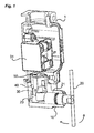
- the position switch of the invention comprises a body 1 on which a control head 10 is mounted, said head 10 comprising a rotary lever 20 operable pivotally about an axis of rotation (R) under the effect of an outside action.
- the body 1 of the switch contains a pusher 30 operable in translation along a translation axis (X) perpendicular to the axis of rotation (R) of the lever 20 and a switch assembly 31 for controlling an electric detection circuit.
- This switch assembly comprises one or more movable contacts 310 moved by the pusher 30 and actuated relative to one or more fixed contacts 311 for controlling the electrical detection circuit.
- the Figures 2 to 4 show for example a bridge with double contacts.
- the body 1 also encloses a control shaft 21 integral in rotation with the lever 20 and intended to act on the pusher 30 to actuate the movable contacts 310.
- the control shaft 21 comprises a cam 22 intended to transform the movement of the rotation of the control shaft 21 in a translational movement of the pusher 30.
- the rotary lever 20 is capable of taking at least two distinct positions, preferably three distinct positions composed of a median rest position and two extreme angular positions, opposite to the median position.
- the two opposite extreme positions are for example located at + 90 ° and -90 ° relative to the rest position.
- a return spring (not visible in the figures) makes it possible to return the lever 20 towards its rest position.
- the pusher 30 In the rest position, the pusher 30 is in a first position and the contacts are in a first state (for example in the open state - figure 2 ) and in the two opposite extreme positions, the pusher 30 is in a second position and the contacts are in a second state (for example in the closed state - figure 4 ).
- the cam 22 is thus formed symmetrically so that in each of the two extreme positions, the pusher 30 is in its second position. Between the two positions, the moving contacts 310 are being closed ( figure 3 ).
- the body 1 of the switch also contains locking means for immobilizing the control shaft 21 and therefore the lever 20 in each of its extreme positions and thus maintain the contacts in their second state. if the external action acting on the lever 20 has disappeared. According to the invention, these locking means thus make it possible to memorize the state of the contacts and the position of the lever 20 and the control shaft 21 even if the external action is no longer present.
- the locking means of the invention cooperate with another cam 23, integral in rotation with the control shaft and for example made on the control shaft 21.
- These locking means comprise a guide 40 operable in translation along an axis parallel to the axis of translation (X) and applied against the cam 23 by means of a spring 50 bearing on the one hand against the guide 40 and on the other hand against a fixed part relative to the body of the switch, for example against the housing of the switch assembly 31 ( Figures 2 to 4 ).
- the pusher 30 is for example arranged inside the guide in order to save space ( figure 1 ), the two parts moving in translation relative to each other each actuated by their cam 22, 23 during the rotation of the control shaft 21.
- the guide 40 comprises for example a deported branch intended to rest on the cam 23, under the action of the spring 50, to block the rotation of the shaft 21 and maintain it in each of its positions.
- the cam 23 has, for example, three successive flat faces each formed at 90 ° from each other, said faces each serving as support for the part of the guide 40 in order to define each one of the three different positions of the lever. 20.
- the guide In each position of the lever 20, the guide thus bears against a different face of the cam 23. The faces being at 90 ° to each other, the control shaft is thus immobilized in each of its positions.
- the lever In the initial state, the lever is in the rest position, the contacts are in their first state, for example in the open state
- the guide 40 is resting on a first face 230 of the cam 23 ( figure 2 ).
- the cam 22 actuates the pusher in translation towards its second position ( figure 3 ) and the cam 23 also moves the guide 40 in translation against the spring 50.
- the pusher In one of the extreme positions of the lever 20, the pusher is in its second position and the contacts are in their second state, for example in the closed state ( figure 4 ).
- the guide 40 then comes to bear against the adjacent face 231 of the cam 23 under the action of the spring 50, to block the rotation of the shaft and therefore the translation of the pusher 30.
- the position of the lever 20 is stored in memory and the state of the contacts is maintained by blocking the rotation of the shaft 21 by the support of the guide 40 against the cam 23.
Landscapes
- Rotary Switch, Piano Key Switch, And Lever Switch (AREA)
- Switches With Compound Operations (AREA)
- Control Of Position Or Direction (AREA)
- Fittings On The Vehicle Exterior For Carrying Loads, And Devices For Holding Or Mounting Articles (AREA)
- Electrophonic Musical Instruments (AREA)
Description
- La présente invention se rapporte à un interrupteur de position présentant une fonction de mémorisation. L'interrupteur de position comporte un levier rotatif actionnable en pivotement sous l'influence d'une action extérieure.
- Un interrupteur de position tel que décrit dans le document
EP1302956 (ouUS6627827 ) comporte un corps renfermant un poussoir déplaçable entre deux positions selon un axe de translation, un ensemble interrupteur destiné à commander un circuit électrique et actionnable par le poussoir et un arbre de commande actionnable en rotation entre au moins deux positions angulaires suivant un axe de rotation perpendiculaire à l'axe de translation du poussoir et coopérant avec le poussoir pour le déplacer entre ses deux positions. En pivotant, un levier rotatif monté sur l'arbre de commande permet de détecter une action extérieure. - Il est également connu du document
US 5,028,748 un interrupteur de position dans lequel des moyens permettent, après actionnement, de freiner le retour du levier rotatif vers sa position de repos. Ces moyens comportent par exemple une bille montée sur un ressort et destinée à s'appliquer sur une came solidaire en rotation de l'arbre de commande pour freiner le retour du levier rotatif vers sa position de repos et éviter ainsi les phénomènes de cognement ou de rebond. - Dans les interrupteurs de position de l'art antérieur, en cas de perte de l'action extérieure ayant entraînée le changement d'état des contacts, le levier rotatif revient automatiquement vers sa position de repos initiale, modifiant alors l'état des contacts.
- Le document
US-A-3 126 460 décrit un interrupteur selon le préambule de la revendication 1. - Le but de l'invention est de proposer un interrupteur de position dans lequel, en cas de perte de l'action extérieure qui a occasionné un changement d'état des contacts, l'état des contacts et la position angulaire du levier sont mémorisés
- Ce but est atteint par un interrupteur de position selon la revendication 1.
- Selon une particularité, la première came est réalisée sur l'arbre de commande.
- Selon une autre particularité, l'arbre de commande est actionnable en rotation entre trois positions angulaires, une position médiane de repos et deux positions opposées par rapport à la position médiane.
- Selon une autre particularité, la première came présente trois faces planes correspondant chacune à une position différente de l'arbre de commande.
- Selon une autre particularité, l'interrupteur de position comporte une seconde came solidaire en rotation de l'arbre de commande et un suiveur de came solidaire du poussoir.
- D'autres caractéristiques et avantages vont apparaître dans la description détaillée qui suit en se référant à un mode de réalisation donné à titre d'exemple et représenté par les dessins annexés sur lesquels :
- la
figure 1 représente en perspective, l'interrupteur de position de l'invention, et montre plus particulièrement l'architecture interne de l'interrupteur, - les
figures 2 à 4 représentent schématiquement l'interrupteur de position de l'invention respectivement lorsque les contacts sont à l'état ouvert, en cours de fermeture et à l'état fermé. Sur lafigure 2 , le levier rotatif est en position verticale. Sur lafigure 3 le levier rotatif est tourné à environ à 45° par rapport à la position verticale initiale. Sur lafigure 4 , le levier rotatif est tourné à 90° par rapport à la position verticale initiale. - L'interrupteur de position de l'invention comporte un corps 1 sur lequel est montée une tête de commande 10, ladite tête 10 comportant un levier rotatif 20 actionnable en pivotement autour d'un axe de rotation (R) sous l'effet d'une action extérieure. Le corps 1 de l'interrupteur renferme un poussoir 30 actionnable en translation suivant un axe de translation (X) perpendiculaire à l'axe de rotation (R) du levier 20 et un ensemble interrupteur 31 destiné à commander un circuit électrique de détection. Cet ensemble interrupteur comporte un ou plusieurs contacts mobiles 310 mis en mouvement par le poussoir 30 et actionnés par rapport à un ou plusieurs contacts fixes 311 pour commander le circuit électrique de détection. Les
figures 2 à 4 montrent par exemple un pont à double contacts. Le corps 1 renferme également un arbre de commande 21 solidaire en rotation du levier 20 et destiné à agir sur le poussoir 30 pour actionner les contacts mobiles 310. Pour cela, l'arbre de commande 21 comporte une came 22 destinée à transformer le mouvement de rotation de l'arbre de commande 21 en un mouvement de translation du poussoir 30. - Le levier rotatif 20 est susceptible de prendre au moins deux positions distinctes, préférentiellement trois positions distinctes composées d'une position de repos médiane et de deux positions angulaires extrêmes, opposées par rapport à la position médiane. Les deux positions extrêmes opposées sont par exemple situées à +90° et -90° par rapport à la position de repos. Un ressort de rappel (non visible sur les figures) permet de ramener le levier 20 vers sa position de repos. En position de repos, le poussoir 30 est dans une première position et les contacts sont dans un premier état (par exemple à l'état ouvert -
figure 2 ) et dans les deux positions extrêmes opposées, le poussoir 30 est dans une seconde position et les contacts sont dans un second état (par exemple à l'état fermé -figure 4 ). La came 22 est ainsi formée de manière symétrique pour que dans chacune des deux positions extrêmes, le poussoir 30 soit dans sa seconde position. Entre les deux positions, les contacts mobiles 310 sont en cours de fermeture (figure 3 ). - Selon l'invention, le corps 1 de l'interrupteur renferme également des moyens de blocage permettant d'immobiliser l'arbre de commande 21 et donc le levier 20 dans chacune de ses positions extrêmes et ainsi de maintenir les contacts dans leur second état même si l'action extérieure agissant sur le levier 20 a disparu. Selon l'invention, ces moyens de blocage permettent donc de mémoriser l'état des contacts et la position du levier 20 et de l'arbre de commande 21 même si l'action extérieure n'est plus présente.
- Les moyens de blocage de l'invention coopèrent avec une autre came 23, solidaire en rotation de l'arbre de commande et par exemple réalisée sur l'arbre de commande 21. Ces moyens de blocage comportent un guide 40 actionnable en translation suivant un axe parallèle à l'axe de translation (X) et appliqué contre la came 23 à l'aide d'un ressort 50 prenant appui d'une part contre le guide 40 et d'autre part contre une partie fixe par rapport au corps de l'interrupteur, par exemple contre le boîtier de l'ensemble interrupteur 31 (
figures 2 à 4 ). Le poussoir 30 est par exemple agencé à l'intérieur du guide afin de gagner en encombrement (figure 1 ), les deux pièces se déplaçant en translation l'une par rapport à l'autre actionnées chacune par leur came 22, 23 lors de la rotation de l'arbre de commande 21. Selon l'invention, le guide 40 comporte par exemple une branche déportée destinée à s'appuyer sur la came 23, sous l'action du ressort 50, pour bloquer la rotation de l'arbre 21 et le maintenir dans chacune de ses positions. La came 23 présente par exemple trois faces planes successives formées chacune à 90° l'une de l'autre, lesdites faces servant chacune d'appui pour la partie du guide 40 en vue de définir chacune l'une des trois positions différentes du levier 20. Dans chaque position du levier 20, le guide vient donc prendre appui contre une face différente de la came 23. Les faces étant à 90° l'une de l'autre, l'arbre de commande est donc immobilisé dans chacune de ses positions. - Le fonctionnement de l'interrupteur de position de l'invention est le suivant :
- A l'état initial, le levier est en position de repos, les contacts sont dans leur premier état, par exemple à l'état ouvert Le guide 40 est en appui sur une première face 230 de la came 23 (
figure 2 ). Lors de la rotation du levier 20 vers l'une de ses positions extrêmes, la came 22 actionne le poussoir en translation vers sa seconde position (figure 3 ) et la came 23 déplace également le guide 40 en translation à l'encontre du ressort 50. Dans l'une des positions extrêmes du levier 20, le poussoir est dans sa seconde position et les contacts sont dans leur second état, par exemple à l'état fermé (figure 4 ). Le guide 40 vient alors s'appuyer contre la face adjacente 231 de la came 23 sous l'action du ressort 50, permettant de bloquer la rotation de l'arbre et donc la translation du poussoir 30. La position du levier 20 est donc mémorisée et l'état des contacts est maintenu en bloquant la rotation de l'arbre 21 par l'appui du guide 40 contre la came 23.
Claims (5)
- Interrupteur de position comprenant un corps (1) renfermant :- un poussoir (30) déplaçable entre deux positions selon un axe de translation (X),- un ensemble interrupteur (31) destiné à commander un circuit électrique et actionnable par le poussoir (30),- un arbre de commande (21) actionnable en rotation entre au moins deux positions angulaires suivant un axe de rotation (R) perpendiculaire à l'axe de translation (X) du poussoir (30) et coopérant avec le poussoir (30) pour le déplacer entre ses deux positions,caractérisé en ce que l'interrupteur comporte :- une première came (23) solidaire en rotation de l'arbre de commande (21),- un guide (40) coopérant avec la première came (23) pour immobiliser l'arbre de commande (21) dans chacune de ses positions,- un ressort (50) pris entre le guide (40) et le corps (1) afin d'appliquer le guide (40) contre la première came (23),- le poussoir (30) étant agencé à l'intérieur du guide (40) et le guide (40) étant apte à se déplacer en translation suivant un axe de translation parallèle à l'axe de translation du poussoir (30).
- Interrupteur selon la revendication 1, caractérisé en ce que la première came (23) est réalisée sur l'arbre de commande (21).
- Interrupteur de position la revendication 1 ou 2, caractérisé en ce que l'arbre de commande (21) est actionnable en rotation entre trois positions angulaires, une position médiane de repos et deux positions opposées par rapport à la position médiane.
- Interrupteur de position selon la revendication 3, caractérisé en ce que la première came (23) présente trois faces planes distinctes correspondant chacune à l'une des trois positions de l'arbre de commande.
- Interrupteur de position selon l'une des revendications 1 à 4, caractérisé en ce qu'il comporte une seconde came (22) solidaire en rotation de l'arbre de commande (21) et un suiveur de came solidaire du poussoir (30).
Applications Claiming Priority (1)
| Application Number | Priority Date | Filing Date | Title |
|---|---|---|---|
| FR0901545A FR2943839B1 (fr) | 2009-03-30 | 2009-03-30 | Interrupteur de position |
Publications (2)
| Publication Number | Publication Date |
|---|---|
| EP2237299A1 EP2237299A1 (fr) | 2010-10-06 |
| EP2237299B1 true EP2237299B1 (fr) | 2011-06-22 |
Family
ID=41259617
Family Applications (1)
| Application Number | Title | Priority Date | Filing Date |
|---|---|---|---|
| EP10157339A Active EP2237299B1 (fr) | 2009-03-30 | 2010-03-23 | Interrupteur de position |
Country Status (4)
| Country | Link |
|---|---|
| EP (1) | EP2237299B1 (fr) |
| AT (1) | ATE514172T1 (fr) |
| ES (1) | ES2364178T3 (fr) |
| FR (1) | FR2943839B1 (fr) |
Family Cites Families (7)
| Publication number | Priority date | Publication date | Assignee | Title |
|---|---|---|---|---|
| LU37633A1 (fr) * | 1961-04-05 | 1960-03-08 | ||
| FR1527953A (fr) * | 1966-04-09 | 1968-06-07 | Telemeccanica Elettrica Ing Am | Perfectionnement aux dispositifs interrupteurs ou commutateurs de commande actionnés par des organes mobiles |
| JPS57162219A (en) * | 1981-03-30 | 1982-10-06 | Omron Tateisi Electronics Co | Holding type sealed switch |
| GB2135517A (en) * | 1983-02-15 | 1984-08-30 | Crabtree Electrical Ind Ltd | Operating mechanism for limit switches |
| DE3729303A1 (de) * | 1987-09-02 | 1989-03-16 | Licentia Gmbh | Schaltgeraet |
| US5028748A (en) | 1989-03-28 | 1991-07-02 | Omron Corporation | Limit switch |
| FR2830981B1 (fr) | 2001-10-15 | 2004-10-15 | Schneider Electric Ind Sa | Interrupteur, notamment de position, a tete orientable |
-
2009
- 2009-03-30 FR FR0901545A patent/FR2943839B1/fr not_active Expired - Fee Related
-
2010
- 2010-03-23 ES ES10157339T patent/ES2364178T3/es active Active
- 2010-03-23 EP EP10157339A patent/EP2237299B1/fr active Active
- 2010-03-23 AT AT10157339T patent/ATE514172T1/de not_active IP Right Cessation
Also Published As
| Publication number | Publication date |
|---|---|
| EP2237299A1 (fr) | 2010-10-06 |
| ES2364178T3 (es) | 2011-08-26 |
| ATE514172T1 (de) | 2011-07-15 |
| FR2943839A1 (fr) | 2010-10-01 |
| FR2943839B1 (fr) | 2011-07-29 |
Similar Documents
| Publication | Publication Date | Title |
|---|---|---|
| EP2858081B1 (fr) | Interrupteur de position | |
| EP2061059B1 (fr) | Dispositif de commande d'un appareil électrique de coupure, et appareil électrique de coupure le comportant | |
| CH620014A5 (fr) | ||
| EP2332158B1 (fr) | Dispositif d'arret d'urgence | |
| EP2061058B1 (fr) | Dispositif de commande d'un appareil de coupure électrique et appareil de coupure électrique le comportant | |
| EP1873807B1 (fr) | Appareil de protection electrique commande par un dispositif de commande auxiliaire | |
| EP2237299B1 (fr) | Interrupteur de position | |
| FR2717617A1 (fr) | Perfectionnement aux interrupteurs différentiels. | |
| EP2083434B1 (fr) | Système de signalisation d'un défaut électrique dans un appareil de coupure | |
| EP3109878A1 (fr) | Ampoule à vide et appareillage de protection électrique comportant une telle ampoule | |
| FR3108884A1 (fr) | Volant de vehicule | |
| EP2717284B1 (fr) | Dispositif de commande d'un appareil de protection électrique et appareil de protection électrique le comportant | |
| FR3056330A1 (fr) | Dispositif de coupure comportant un organe de rearmement | |
| EP2564408B1 (fr) | Dispositif d'arret d'urgence | |
| FR2769037A1 (fr) | Dispositif de verrouillage comportant un doigt de transmission commande par came | |
| EP2061060B1 (fr) | Appareil électrique de coupure tel un disjoncteur ou un interrupteur | |
| FR2793751A1 (fr) | Dispositif de verrouillage de direction pour un ensemble de direction pour vehicule | |
| FR2534421A1 (fr) | ||
| FR3051593A1 (fr) | Dispositif de signalisation d'un defaut electrique dans un appareil de protection electrique, et appareil de protection electrique comportant un tel dispositif. | |
| CH716204B1 (fr) | Combiné disjoncteur et interrupteur sectionneur. | |
| EP4465326A1 (fr) | Mécanisme de commande d'un dispositif de coupure du courant | |
| FR2842492A1 (fr) | Dispositif d'arret et de detection de la position d'un ouvrant de vehicule automobile, et vehicule equipe d'un tel dispositif | |
| EP2545574A1 (fr) | Interrupteur electrique moyenne et haute tension avec retour sur fermeture et dispositif d'insertion d'une resistance | |
| FR3000597A1 (fr) | Selecteur de commande. | |
| FR2891393A1 (fr) | Dispositif de commande comportant un mecanisme de point dur et actionnant des contacts electriques |
Legal Events
| Date | Code | Title | Description |
|---|---|---|---|
| PUAI | Public reference made under article 153(3) epc to a published international application that has entered the european phase |
Free format text: ORIGINAL CODE: 0009012 |
|
| AK | Designated contracting states |
Kind code of ref document: A1 Designated state(s): AT BE BG CH CY CZ DE DK EE ES FI FR GB GR HR HU IE IS IT LI LT LU LV MC MK MT NL NO PL PT RO SE SI SK SM TR |
|
| AX | Request for extension of the european patent |
Extension state: AL BA ME RS |
|
| RIN1 | Information on inventor provided before grant (corrected) |
Inventor name: GAILLEDRAT, JOEL |
|
| 17P | Request for examination filed |
Effective date: 20110112 |
|
| GRAP | Despatch of communication of intention to grant a patent |
Free format text: ORIGINAL CODE: EPIDOSNIGR1 |
|
| RIC1 | Information provided on ipc code assigned before grant |
Ipc: H01H 21/34 20060101AFI20110318BHEP |
|
| GRAS | Grant fee paid |
Free format text: ORIGINAL CODE: EPIDOSNIGR3 |
|
| GRAA | (expected) grant |
Free format text: ORIGINAL CODE: 0009210 |
|
| AK | Designated contracting states |
Kind code of ref document: B1 Designated state(s): AT BE BG CH CY CZ DE DK EE ES FI FR GB GR HR HU IE IS IT LI LT LU LV MC MK MT NL NO PL PT RO SE SI SK SM TR |
|
| REG | Reference to a national code |
Ref country code: GB Ref legal event code: FG4D Free format text: NOT ENGLISH |
|
| REG | Reference to a national code |
Ref country code: CH Ref legal event code: EP |
|
| REG | Reference to a national code |
Ref country code: IE Ref legal event code: FG4D Free format text: LANGUAGE OF EP DOCUMENT: FRENCH |
|
| REG | Reference to a national code |
Ref country code: DE Ref legal event code: R096 Ref document number: 602010000076 Country of ref document: DE Effective date: 20110804 |
|
| REG | Reference to a national code |
Ref country code: ES Ref legal event code: FG2A Ref document number: 2364178 Country of ref document: ES Kind code of ref document: T3 Effective date: 20110826 |
|
| REG | Reference to a national code |
Ref country code: NL Ref legal event code: VDEP Effective date: 20110622 |
|
| PG25 | Lapsed in a contracting state [announced via postgrant information from national office to epo] |
Ref country code: SE Free format text: LAPSE BECAUSE OF FAILURE TO SUBMIT A TRANSLATION OF THE DESCRIPTION OR TO PAY THE FEE WITHIN THE PRESCRIBED TIME-LIMIT Effective date: 20110622 Ref country code: LT Free format text: LAPSE BECAUSE OF FAILURE TO SUBMIT A TRANSLATION OF THE DESCRIPTION OR TO PAY THE FEE WITHIN THE PRESCRIBED TIME-LIMIT Effective date: 20110622 Ref country code: NO Free format text: LAPSE BECAUSE OF FAILURE TO SUBMIT A TRANSLATION OF THE DESCRIPTION OR TO PAY THE FEE WITHIN THE PRESCRIBED TIME-LIMIT Effective date: 20110922 Ref country code: HR Free format text: LAPSE BECAUSE OF FAILURE TO SUBMIT A TRANSLATION OF THE DESCRIPTION OR TO PAY THE FEE WITHIN THE PRESCRIBED TIME-LIMIT Effective date: 20110622 |
|
| PG25 | Lapsed in a contracting state [announced via postgrant information from national office to epo] |
Ref country code: CY Free format text: LAPSE BECAUSE OF FAILURE TO SUBMIT A TRANSLATION OF THE DESCRIPTION OR TO PAY THE FEE WITHIN THE PRESCRIBED TIME-LIMIT Effective date: 20110622 Ref country code: FI Free format text: LAPSE BECAUSE OF FAILURE TO SUBMIT A TRANSLATION OF THE DESCRIPTION OR TO PAY THE FEE WITHIN THE PRESCRIBED TIME-LIMIT Effective date: 20110622 Ref country code: GR Free format text: LAPSE BECAUSE OF FAILURE TO SUBMIT A TRANSLATION OF THE DESCRIPTION OR TO PAY THE FEE WITHIN THE PRESCRIBED TIME-LIMIT Effective date: 20110923 Ref country code: SI Free format text: LAPSE BECAUSE OF FAILURE TO SUBMIT A TRANSLATION OF THE DESCRIPTION OR TO PAY THE FEE WITHIN THE PRESCRIBED TIME-LIMIT Effective date: 20110622 Ref country code: AT Free format text: LAPSE BECAUSE OF FAILURE TO SUBMIT A TRANSLATION OF THE DESCRIPTION OR TO PAY THE FEE WITHIN THE PRESCRIBED TIME-LIMIT Effective date: 20110622 Ref country code: LV Free format text: LAPSE BECAUSE OF FAILURE TO SUBMIT A TRANSLATION OF THE DESCRIPTION OR TO PAY THE FEE WITHIN THE PRESCRIBED TIME-LIMIT Effective date: 20110622 |
|
| PG25 | Lapsed in a contracting state [announced via postgrant information from national office to epo] |
Ref country code: NL Free format text: LAPSE BECAUSE OF FAILURE TO SUBMIT A TRANSLATION OF THE DESCRIPTION OR TO PAY THE FEE WITHIN THE PRESCRIBED TIME-LIMIT Effective date: 20110622 |
|
| REG | Reference to a national code |
Ref country code: IE Ref legal event code: FD4D |
|
| PG25 | Lapsed in a contracting state [announced via postgrant information from national office to epo] |
Ref country code: CZ Free format text: LAPSE BECAUSE OF FAILURE TO SUBMIT A TRANSLATION OF THE DESCRIPTION OR TO PAY THE FEE WITHIN THE PRESCRIBED TIME-LIMIT Effective date: 20110622 Ref country code: IS Free format text: LAPSE BECAUSE OF FAILURE TO SUBMIT A TRANSLATION OF THE DESCRIPTION OR TO PAY THE FEE WITHIN THE PRESCRIBED TIME-LIMIT Effective date: 20111022 Ref country code: IE Free format text: LAPSE BECAUSE OF FAILURE TO SUBMIT A TRANSLATION OF THE DESCRIPTION OR TO PAY THE FEE WITHIN THE PRESCRIBED TIME-LIMIT Effective date: 20110622 Ref country code: PT Free format text: LAPSE BECAUSE OF FAILURE TO SUBMIT A TRANSLATION OF THE DESCRIPTION OR TO PAY THE FEE WITHIN THE PRESCRIBED TIME-LIMIT Effective date: 20111024 Ref country code: EE Free format text: LAPSE BECAUSE OF FAILURE TO SUBMIT A TRANSLATION OF THE DESCRIPTION OR TO PAY THE FEE WITHIN THE PRESCRIBED TIME-LIMIT Effective date: 20110622 |
|
| PG25 | Lapsed in a contracting state [announced via postgrant information from national office to epo] |
Ref country code: SK Free format text: LAPSE BECAUSE OF FAILURE TO SUBMIT A TRANSLATION OF THE DESCRIPTION OR TO PAY THE FEE WITHIN THE PRESCRIBED TIME-LIMIT Effective date: 20110622 Ref country code: PL Free format text: LAPSE BECAUSE OF FAILURE TO SUBMIT A TRANSLATION OF THE DESCRIPTION OR TO PAY THE FEE WITHIN THE PRESCRIBED TIME-LIMIT Effective date: 20110622 |
|
| PLBE | No opposition filed within time limit |
Free format text: ORIGINAL CODE: 0009261 |
|
| STAA | Information on the status of an ep patent application or granted ep patent |
Free format text: STATUS: NO OPPOSITION FILED WITHIN TIME LIMIT |
|
| 26N | No opposition filed |
Effective date: 20120323 |
|
| PG25 | Lapsed in a contracting state [announced via postgrant information from national office to epo] |
Ref country code: DK Free format text: LAPSE BECAUSE OF FAILURE TO SUBMIT A TRANSLATION OF THE DESCRIPTION OR TO PAY THE FEE WITHIN THE PRESCRIBED TIME-LIMIT Effective date: 20110622 |
|
| REG | Reference to a national code |
Ref country code: DE Ref legal event code: R097 Ref document number: 602010000076 Country of ref document: DE Effective date: 20120323 |
|
| BERE | Be: lapsed |
Owner name: SCHNEIDER ELECTRIC INDUSTRIES SAS Effective date: 20120331 |
|
| PG25 | Lapsed in a contracting state [announced via postgrant information from national office to epo] |
Ref country code: MC Free format text: LAPSE BECAUSE OF NON-PAYMENT OF DUE FEES Effective date: 20120331 |
|
| PG25 | Lapsed in a contracting state [announced via postgrant information from national office to epo] |
Ref country code: BE Free format text: LAPSE BECAUSE OF NON-PAYMENT OF DUE FEES Effective date: 20120331 |
|
| PG25 | Lapsed in a contracting state [announced via postgrant information from national office to epo] |
Ref country code: MK Free format text: LAPSE BECAUSE OF FAILURE TO SUBMIT A TRANSLATION OF THE DESCRIPTION OR TO PAY THE FEE WITHIN THE PRESCRIBED TIME-LIMIT Effective date: 20110622 |
|
| PG25 | Lapsed in a contracting state [announced via postgrant information from national office to epo] |
Ref country code: BG Free format text: LAPSE BECAUSE OF FAILURE TO SUBMIT A TRANSLATION OF THE DESCRIPTION OR TO PAY THE FEE WITHIN THE PRESCRIBED TIME-LIMIT Effective date: 20110922 |
|
| PG25 | Lapsed in a contracting state [announced via postgrant information from national office to epo] |
Ref country code: MT Free format text: LAPSE BECAUSE OF FAILURE TO SUBMIT A TRANSLATION OF THE DESCRIPTION OR TO PAY THE FEE WITHIN THE PRESCRIBED TIME-LIMIT Effective date: 20110622 |
|
| PG25 | Lapsed in a contracting state [announced via postgrant information from national office to epo] |
Ref country code: TR Free format text: LAPSE BECAUSE OF FAILURE TO SUBMIT A TRANSLATION OF THE DESCRIPTION OR TO PAY THE FEE WITHIN THE PRESCRIBED TIME-LIMIT Effective date: 20110622 |
|
| PG25 | Lapsed in a contracting state [announced via postgrant information from national office to epo] |
Ref country code: LU Free format text: LAPSE BECAUSE OF NON-PAYMENT OF DUE FEES Effective date: 20120323 Ref country code: SM Free format text: LAPSE BECAUSE OF FAILURE TO SUBMIT A TRANSLATION OF THE DESCRIPTION OR TO PAY THE FEE WITHIN THE PRESCRIBED TIME-LIMIT Effective date: 20110622 |
|
| PG25 | Lapsed in a contracting state [announced via postgrant information from national office to epo] |
Ref country code: HU Free format text: LAPSE BECAUSE OF FAILURE TO SUBMIT A TRANSLATION OF THE DESCRIPTION OR TO PAY THE FEE WITHIN THE PRESCRIBED TIME-LIMIT Effective date: 20100323 |
|
| REG | Reference to a national code |
Ref country code: CH Ref legal event code: PL |
|
| GBPC | Gb: european patent ceased through non-payment of renewal fee |
Effective date: 20140323 |
|
| PG25 | Lapsed in a contracting state [announced via postgrant information from national office to epo] |
Ref country code: LI Free format text: LAPSE BECAUSE OF NON-PAYMENT OF DUE FEES Effective date: 20140331 Ref country code: GB Free format text: LAPSE BECAUSE OF NON-PAYMENT OF DUE FEES Effective date: 20140323 Ref country code: CH Free format text: LAPSE BECAUSE OF NON-PAYMENT OF DUE FEES Effective date: 20140331 |
|
| REG | Reference to a national code |
Ref country code: FR Ref legal event code: PLFP Year of fee payment: 7 |
|
| REG | Reference to a national code |
Ref country code: FR Ref legal event code: PLFP Year of fee payment: 8 |
|
| REG | Reference to a national code |
Ref country code: FR Ref legal event code: PLFP Year of fee payment: 9 |
|
| PGFP | Annual fee paid to national office [announced via postgrant information from national office to epo] |
Ref country code: DE Payment date: 20240319 Year of fee payment: 15 |
|
| PGFP | Annual fee paid to national office [announced via postgrant information from national office to epo] |
Ref country code: IT Payment date: 20240326 Year of fee payment: 15 Ref country code: FR Payment date: 20240321 Year of fee payment: 15 |
|
| PGFP | Annual fee paid to national office [announced via postgrant information from national office to epo] |
Ref country code: ES Payment date: 20240411 Year of fee payment: 15 |
|
| REG | Reference to a national code |
Ref country code: DE Ref legal event code: R081 Ref document number: 602010000076 Country of ref document: DE Owner name: TMSS FRANCE, FR Free format text: FORMER OWNER: SCHNEIDER ELECTRIC INDUSTRIES SAS, RUEIL-MALMAISON, FR |
|
| REG | Reference to a national code |
Ref country code: DE Ref legal event code: R119 Ref document number: 602010000076 Country of ref document: DE |
|
| REG | Reference to a national code |
Ref country code: ES Ref legal event code: PC2A Owner name: TMSS FRANC Effective date: 20251114 |
|
| PG25 | Lapsed in a contracting state [announced via postgrant information from national office to epo] |
Ref country code: DE Free format text: LAPSE BECAUSE OF NON-PAYMENT OF DUE FEES Effective date: 20251001 |
|
| PG25 | Lapsed in a contracting state [announced via postgrant information from national office to epo] |
Ref country code: IT Free format text: LAPSE BECAUSE OF NON-PAYMENT OF DUE FEES Effective date: 20250323 Ref country code: FR Free format text: LAPSE BECAUSE OF NON-PAYMENT OF DUE FEES Effective date: 20250331 |