EP2237128A1 - Vorgesteuerte Druckproportionalventilanordnung mit einer durch eine elektronische Regelungseinrichtung angesteuerten Vorsteuerstufe - Google Patents
Vorgesteuerte Druckproportionalventilanordnung mit einer durch eine elektronische Regelungseinrichtung angesteuerten Vorsteuerstufe Download PDFInfo
- Publication number
- EP2237128A1 EP2237128A1 EP10003415A EP10003415A EP2237128A1 EP 2237128 A1 EP2237128 A1 EP 2237128A1 EP 10003415 A EP10003415 A EP 10003415A EP 10003415 A EP10003415 A EP 10003415A EP 2237128 A1 EP2237128 A1 EP 2237128A1
- Authority
- EP
- European Patent Office
- Prior art keywords
- pressure
- valve
- pilot
- arrangement according
- venting
- Prior art date
- Legal status (The legal status is an assumption and is not a legal conclusion. Google has not performed a legal analysis and makes no representation as to the accuracy of the status listed.)
- Granted
Links
Images

Classifications
-
- G—PHYSICS
- G05—CONTROLLING; REGULATING
- G05D—SYSTEMS FOR CONTROLLING OR REGULATING NON-ELECTRIC VARIABLES
- G05D16/00—Control of fluid pressure
- G05D16/20—Control of fluid pressure characterised by the use of electric means
- G05D16/2093—Control of fluid pressure characterised by the use of electric means with combination of electric and non-electric auxiliary power
- G05D16/2095—Control of fluid pressure characterised by the use of electric means with combination of electric and non-electric auxiliary power using membranes within the main valve
Definitions
- the invention relates to a pilot-operated pressure proportional valve arrangement with a control stage controlled by an electronic control device and a pressure-controlled main stage having a valve member with the features of the preamble of claim 1.
- a pilot-operated pressure proportional valve arrangement wherein the pressure control valve has a pilot chamber, which can be acted upon by means of a venting valve and a venting valve with control pressure.
- a piston is provided as a movable partition wall between the pilot chamber and a working chamber.
- Conventional pressure proportional valves have two operating states, the pressure control mode and a zero shutdown mode.
- the pressure control mode is active within the allowable target pressure range, which typically ranges from 1% of the maximum operating pressure to the maximum operating pressure. Becomes the permissible minimum setpoint is exceeded, the valve goes into the zero shutdown mode, and the working port is brought into a controlled continuous ventilation state, which must be maintained until the setpoint specification exceeds the permissible minimum value again.
- the vent valve is deactivated or closed in a known manner, and the vent valve of the pilot stage is actuated until the zero shutdown mode is completed, the setpoint again rises above the permissible minimum setpoint.
- An object of the present invention is to provide a pilot-operated pressure proportional valve arrangement of the type mentioned, in the zero-shutdown mode, a safe venting of the pilot chamber and thus the working chamber is ensured with only low energy consumption without the heat problems described arise.
- the solution according to the invention has the advantage that the vent valve in the zero-shutdown mode is always operated only briefly, namely only until the actual working pressure below has dropped to the predetermined actual limits. As a result, the energy consumption is significantly reduced and prevents heating of the vent valve and the corresponding heat radiation to the environment. At the same time, the service life increases.
- control device may also have second control means for cyclically opening the venting valve for a brief time during the specification of a desired working pressure below the predefinable setpoint threshold value and for closing the venting valve by the first control means.
- second control means for cyclically opening the venting valve for a brief time during the specification of a desired working pressure below the predefinable setpoint threshold value and for closing the venting valve by the first control means.
- control device has third control means for opening the vent valve when the actual working pressure rises above the predefinable actual limit value. So should the pressure in the pilot chamber despite cyclic opening of the vent valve increase in an undesirable manner, this is effectively prevented by the third control means on reaching the predetermined actual limit value.
- the desired limit value is preferably less than 3% of the maximum working pressure and is preferably substantially 1% of the maximum working pressure, while the actual limit value is significantly smaller and close to zero.
- control means are designed as at least one microcontroller, which is designed in particular for pressure control by the electronic control device by means of the ventilation valve and the vent valve.
- a pressure sensor is expediently arranged as an actual value transmitter and connected to the regulating device.
- this pressure sensor can also be arranged in the pilot chamber, since there is a direct relationship between pilot pressure and working chamber pressure.
- the movable partition is preferably designed as a membrane or piston.
- vent valve and the vent valve are closed in the non-energized state and thereby consume in this state of rest no energy and do not generate unwanted heat.
- the valve member expediently has a spring acting against the opening movement.
- valve member has a venting channel opening into the working chamber, which can be closed by the movable partition wall with appropriate pressurization of the pilot chamber, in particular against the force of a spring.
- pilot-operated pressure proportional valve arrangement shown as an exemplary embodiment consists essentially of a pressure proportional valve 10, which is controlled by an electronic control device 11, wherein the pressure proportional valve 10 has a pilot stage 12 and a main stage 13.
- a housing 14 of the pressure proportional valve 10 has a first, designed as an inlet chamber 15 chamber, a second chamber formed as a working chamber 16 and a third, formed as a pilot chamber 17 chamber. Between the working chamber 16 and the pilot chamber 17 there is a valve seat 18 having intermediate wall 19, and the working chamber 16 is separated from the pilot chamber 17 by a diaphragm formed as a movable partition 20.
- a valve member 21 extends through the inlet chamber 15 and closes the valve seat 18 in the pressureless state by the force of a spring 22, so that no fluid from the inlet chamber 15 through a connection opening 23 to the working chamber 16 can pass.
- An extension 24 of the valve member 21 extends through this connection opening 23 to the partition wall 20 and is applied to this depending on the respective pressure conditions or not.
- a vent channel 25 extends in the longitudinal direction through the valve member 21 and the extension 24 and is sealed in the case of concern to the partition wall 20 by this. If the fluid pressure in the working chamber 16 is greater than that in the pilot chamber 17, the movable dividing wall 20 lifts off from the extension 24, supported by a spring 26, so that the venting channel 25 is opened to vent the working chamber 16.
- valves 27, 28 are designed as electrically controllable valves, for example as solenoid valves, and are controlled by the electronic control device 11.
- the vent valve 27 is connected to the pilot chamber 17 for ventilation with a fluidic pressure source 29, while the vent valve 28 is connected to an outlet 30 in the environment.
- vent valve 27 and the vent valve 28 are formed, for example, as a 2/2-way valve, wherein both valves are closed in the de-energized state.
- a movable partition 20 instead of a membrane, for example, a piston can be used, as described in the above-mentioned prior art.
- the fluidic pressure source 29 is connected to an inlet 31 of the inlet chamber 15, and the working chamber 16 has a regulated working pressure to a consumer, not shown, outlet 32.
- a pressure sensor 33 which detects the working pressure as the actual value, is arranged in the region of the outlet 32, but in principle could also be arranged in the working chamber 16 or in the pilot chamber 17.
- This pressure sensor 33 supplies the detected actual value of the electronic control device 11. This is set via a setpoint input 34, a desired working pressure for the control. This can be set on the control device 11 or supplied from an external device.
- This minimum pressure setpoint Psmin For example, it is set to 1% of maximum operating pressure, but may vary in this low pressure range.
- step 42 If such an undershooting is detected (+), then the vent valve 27 is closed in step 42 and the vent valve 28 is opened in step 43. As a result, the pressure in the pilot chamber 17 and correspondingly by lifting the partition 20 from the extension 24 of the valve member 21 and the pressure in the working chamber 16, so the working pressure decreases.
- the subsequent query sequence 44 is then checked whether the working pressure Pa falls below a predetermined predetermined actual limit or minimum working pressure Pamin, which is substantially lower than the desired limit and, for example, is close to zero. If such an undershooting is detected (+), then in step 45, the vent valve 28 is closed. This is therefore only open during a relatively short energizing phase.
- the venting valve 28 is cyclically actuated according to steps 47 in connection with the query step 51 to ensure that, for example, if the venting valve 27 does not operate correctly, the pressure in the pilot chamber 17 is not inadmissible increases.
- the vent valve 28 is opened, kept open for a very short time t2, for example, under 1 second and then closed again. If, in the inquiry step 51, it is then established that the working pressure Pa is still below the preset actual limit value Pamin (+), the steps 46 to 50 are repeated, ie the cyclic opening of the venting valve 28 is continued. This loop will continue to run until it is determined either in the inquiry step 51 that the actual limit value of the working pressure Pamin is exceeded (-), then in step 43 the venting valve is opened and the step sequence described above is run through again. However, if in this loop the target limit Psmin is exceeded, which is determined in the query step 46, then the pressure control mode 40 is switched back.
- the electronic control device 11 contains corresponding control means which can be implemented in one or more microcontrollers. Alternatively, a realization by an ASIC or another or more IC is possible.
Landscapes
- Physics & Mathematics (AREA)
- Fluid Mechanics (AREA)
- General Physics & Mathematics (AREA)
- Engineering & Computer Science (AREA)
- Automation & Control Theory (AREA)
- Control Of Fluid Pressure (AREA)
- Exhaust-Gas Circulating Devices (AREA)
- Compressors, Vaccum Pumps And Other Relevant Systems (AREA)
Abstract
Description
- Die Erfindung betrifft eine vorgesteuerte Druckproportionalventilanordnung mit einer durch eine elektronische Regelungseinrichtung angesteuerten Vorsteuerstufe und einer ein Ventilglied aufweisenden druckgeregelten Hauptstufe mit den Merkmalen des Oberbegriffs des Anspruchs 1.
- Aus der
DE 298 09 412 U1 ist eine vorgesteuerte Druckproportionalventilanordnung bekannt, wobei das Druckregelventil eine Vorsteuerkammer besitzt, die mittels eines Belüftungsventils und eines Entlüftungsventils mit Steuerdruck beaufschlagbar ist. Als bewegliche Trennwand zwischen der Vorsteuerkammer und einer Arbeitskammer ist ein Kolben vorgesehen. - Aus der
DE 694 22 341 T2 ist bekannt, die Steuerung von Entlüftungsventilen unter Berücksichtigung von Soll- und IstWerten vorzunehmen. - Übliche Druckproportionalventile weisen zwei Betriebszustände auf, den Druckregelmodus und einen Null-Abschaltmodus. Der Druckregelmodus ist im zulässigen Solldruckbereich aktiv, der in der Regel von 1 % des maximalen Betriebsdrucks bis zum maximalen Betriebsdruck reicht. Wird der zulässige Mindestsollwert unterschritten, so geht das Ventil in den Null-Abschaltmodus über, und der Arbeitsanschluss wird in einen gesteuerten Dauerentlüftungszustand gebracht, der so lange aufrechterhalten werden muss, bis die Sollwertvorgabe den zulässigen Mindestwert wieder übersteigt. Um die vorsteuerkammer hierzu sicher zu entlüften, wird in bekannter weise das Belüftungsventil deaktiviert beziehungsweise geschlossen, und das Entlüftungsventil der Vorsteuerstufe wird so lange betätigt, bis der Null-Abschaltmodus beendet ist, der Sollwert also wieder über den zulässigen Mindestsollwert ansteigt. Da dieser Betriebszustand, also der Null-Abschaltmodus, in der Praxis recht häufig und auch über längere Zeiträume hinweg vorliegt, führt dies durch die Dauer der Betätigung zu einer starken Erwärmung des Entlüftungsventils und eine entsprechende Wärmeabstrahlung an die Umgebung. Weiterhin führt der hohe Energieverbrauch durch die Dauerbestromung des Entlüftungsventils zu einer schlechten Energieeffizienz. Darüber hinaus ergeben sich Lebensdauerprobleme und Montagmorgeneffekte bei den Vorsteuerventilen.
- Eine Aufgabe der vorliegenden Erfindung besteht darin, eine vorgesteuerte Druckproportionalventilanordnung der eingangs genannten Gattung zu schaffen, bei der im Null-Abschaltmodus eine sichere Entlüftung der Vorsteuerkammer und damit der Arbeitskammer bei nur geringem Energiebedarf gewährleistet wird, ohne dass die beschriebenen Wärmeprobleme entstehen.
- Diese Aufgabe wird erfindungsgemäß durch eine vorgesteuerte Druckproportionalventilanordnung mit den Merkmalen des Anspruchs 1 gelöst.
- Die erfindungsgemäße Lösung hat den vorteil, dass das Entlüftungsventil im Null-Abschaltmodus immer nur kurzzeitig betätigt wird, nämlich lediglich bis der Ist-Arbeitsdruck unter den vorgebbaren Ist-Grenzwerten abgesunken ist. Hierdurch wird der Energieverbrauch deutlich reduziert und eine Erwärmung des Entlüftungsventils und die entsprechende Wärmeabstrahlung an die Umgebung verhindert. Gleichzeitig erhöht sich die Lebensdauer.
- Durch die in den Unteransprüchen aufgeführten Maßnahmen sind vorteilhafte weiterbildungen und Verbesserungen der im Anspruch 1 angegebenen Druckproportionalventilanordnung möglich.
- In vorteilhafter Weise kann die Regelungseinrichtung noch zweite Steuermittel zum zyklischen, jeweils kurzzeitigen Öffnen des Entlüftungsventils während der Vorgabe eines unter dem vorgebbaren Soll-Grenzwert liegenden Soll-Arbeitsdrucks und nach dem Schließen des Entlüftungsventils durch die ersten Steuermittel aufweisen. Hierdurch wird wirksam verhindert, dass sich das Ventilglied in unerwünschter Weise öffnet, wenn beispielsweise durch einen Defekt des Belüftungsventils oder aufgrund anderer Defekte die Vorsteuerkammer belüftet wird. Ein eventueller Druckanstieg durch eine solche Fehlfunktion wird durch das zyklische Öffnen des Entlüftungsventils wirksam verhindert. Dieses kurzzeitige Öffnen des Entlüftungsventils erfolgt bevorzugt während einer Zeitspanne von weniger als 1 Sekunde, wobei die zykluszeit insbesondere mehrere Sekunden beträgt. Hierdurch wird der Energieverbrauch des Entlüftungsventils nur unwesentlich erhöht.
- Eine noch größere Sicherheit gegen ein unerwünschtes Öffnen des Ventilglieds wird dadurch erreicht, dass die Regelungseinrichtung dritte Steuermittel zum Öffnen des Entlüftungsventils bei Ansteigen des Ist-Arbeitsdrucks über den vorgebbaren Ist-Grenzwert aufweist. Sollte also trotz zyklischem Öffnen des Entlüftungsventils der Druck in der Vorsteuerkammer in unerwünschter Weise ansteigen, so wird dies bei Erreichen des vorgebbaren Ist-Grenzwerts wirksam durch die dritten Steuermittel verhindert.
- Der Soll-Grenzwert ist bevorzugt kleiner als 3 % des maximalen Arbeitsdrucks und beträgt vorzugsweise im Wesentlichen 1 % des maximalen Arbeitsdrucks, während der Ist-Grenzwert deutlich kleiner ist und nahe bei Null liegt.
- In einer vorteilhaften Ausgestaltung der Erfindung sind die Steuermittel als wenigstens ein Mikrocontroller ausgebildet, der insbesondere auch zur Druckregelung durch die elektronische Regelungseinrichtung mittels des Belüftungsventils und des Entlüftungsventils ausgebildet ist.
- Zur Messung des Arbeitsdrucks in der Arbeitskammer oder im Bereich von deren Auslass ist zweckmäßigerweise ein Drucksensor als Istwertgeber angeordnet und mit der Regelungseinrichtung verbunden. Prinzipiell kann dieser Drucksensor auch in der Vorsteuerkammer angeordnet sein, da ein direkter Zusammenhang zwischen vorsteuerdruck und Arbeitskammerdruck besteht.
- Als zweckmäßige konstruktive Ausgestaltung ist die bewegliche Trennwand bevorzugt als Membran oder Kolben ausgebildet.
- Das Belüftungsventil und das Entlüftungsventil sind im nicht bestromten Zustand geschlossen und verbrauchen dadurch in diesem Ruhezustand keine Energie und erzeugen keine unerwünschte Wärme.
- Das ventilglied weist zweckmäßigerweise eine gegen die Öffnungsbewegung wirkende Feder auf.
- In einer zweckmäßigen konstruktiven Ausgestaltung besitzt das Ventilglied einen in der Arbeitskammer mündenden Entlüftungskanal, der bei entsprechender Druckbeaufschlagung der Vorsteuerkammer durch die bewegbare Trennwand verschließbar ist, insbesondere gegen die Kraft einer Feder.
- Ein Ausführungsbeispiel der Erfindung ist in der Zeichnung dargestellt und in der nachfolgenden Beschreibung näher erläutert. Es zeigen:
- Figur 1
- eine Schnittdarstellung eines Druckproportionalven- tils, das durch eine elektronische Regelungsein- richtung über ein Belüftungsventil und ein Entlüf- tungsventil steuerbar beziehungsweise regelbar ist, als Ausführungsbeispiel der Erfindung und
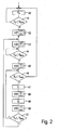
- Figur 2
- ein Flussdiagramm zur Erläuterung der Wirkungs- weise.
- Die in
Figur 1 als Ausführungsbeispiel dargestellte vorgesteuerte Druckproportionalventilanordnung besteht im Wesentlichen aus einem Druckproportionalventil 10, das von einer elektronischen Regelungseinrichtung 11 gesteuert wird, wobei das Druckproportionalventil 10 eine Vorsteuerstufe 12 und eine Hauptstufe 13 aufweist. - Ein Gehäuse 14 des Druckproportionalventils 10 weist eine erste, als Einlasskammer 15 ausgebildete Kammer, eine zweite, als Arbeitskammer 16 ausgebildete Kammer und eine dritte, als Vorsteuerkammer 17 ausgebildete Kammer auf. Zwischen der Arbeitskammer 16 und der Vorsteuerkammer 17 befindet sich eine einen Ventilsitz 18 aufweisende Zwischenwandung 19, und die Arbeitskammer 16 ist von der Vorsteuerkammer 17 durch eine als Membran ausgebildete bewegliche Trennwand 20 getrennt.
- Ein Ventilglied 21 erstreckt sich durch die Einlasskammer 15 und verschließt im drucklosen Zustand durch die Kraft einer Feder 22 den Ventilsitz 18, so dass kein Fluid von der Einlasskammer 15 durch eine Verbindungsöffnung 23 zur Arbeitskammer 16 gelangen kann. Eine Verlängerung 24 des Ventilglieds 21 erstreckt sich durch diese Verbindungsöffnung 23 bis zur Trennwand 20 und liegt an dieser in Abhängigkeit der jeweiligen Druckverhältnisse an oder nicht an. Ein Entlüftungskanal 25 erstreckt sich in Längsrichtung durch das Ventilglied 21 und die Verlängerung 24 und wird im Falle des Anliegens an der Trennwand 20 durch diese dichtend verschlossen. Ist der Fluiddruck in der Arbeitskammer 16 größer als der in der Vorsteuerkammer 17, so hebt die bewegliche Trennwand 20 unterstützt durch eine Feder 26 von der Verlängerung 24 ab, so dass der Entlüftungskanal 25 zur Entlüftung der Arbeitskammer 16 geöffnet wird.
- Während die Einlasskammer 15 und die Arbeitskammer 16 zusammen mit dem Ventilglied 21 die Hauptstufe 13 bilden, weist die Vorsteuerstufe 12 die Vorsteuerkammer 17, ein damit verbundenes Belüftungsventil 27 und ein damit verbundenes Entlüftungsventil 28 auf. Diese beiden Ventile 27, 28 sind als elektrisch steuerbare Ventile, beispielsweise als Magnetventile, ausgebildet und werden durch die elektronische Regelungseinrichtung 11 gesteuert. Das Belüftungsventil 27 ist zur Belüftung der Vorsteuerkammer 17 mit einer fluidischen Druckquelle 29 verbunden, während das Entlüftungsventil 28 mit einem Auslass 30 in die Umgebung verbunden ist.
- Das Belüftungsventil 27 und das Entlüftungsventil 28 sind beispielsweise als 2/2-Wegeventil ausgebildet, wobei im stromlosen Zustand beide Ventile geschlossen sind.
- Als bewegliche Trennwand 20 kann anstelle einer Membran beispielsweise auch ein Kolben eingesetzt werden, wie dies im eingangs angegebenen Stand der Technik beschrieben ist.
- Die fluidische Druckquelle 29 ist mit einem Einlass 31 der Einlasskammer 15 verbunden, und die Arbeitskammer 16 weist einen den geregelten Arbeitsdruck an einen nicht dargestellten Verbraucher weitergebenden Auslass 32 auf. Ein den Arbeitsdruck als Istwert erfassender Drucksensor 33 ist im Bereich des Auslasses 32 angeordnet, könnte prinzipiell jedoch auch in der Arbeitskammer 16 oder auch in der Vorsteuerkammer 17 angeordnet sein. Dieser Drucksensor 33 führt den erfassten Istwert der elektronischen Regelungseinrichtung 11 zu. Dieser wird über einen Sollwert-Eingang 34 ein Soll-Arbeitsdruck für die Regelung vorgegeben. Dieser kann an der Regelungseinrichtung 11 eingestellt oder von einer externen Einrichtung zugeführt werden.
- Die Wirkungsweise der Druckregelung selbst, also der Regelung des Arbeitsdrucks im Druckregelmodus, ist nicht Gegenstand der vorliegenden Erfindung. Hierzu wird auf den eingangs angegebenen Stand der Technik verwiesen. Gegenstand ist vielmehr der Null-Abschaltmodus, der bei Unterschreitung eines zulässigen Mindestsollwerts vorgegeben wird. In diesem Null-Abschaltmodus wird der Arbeitsdruck auf den Wert null oder nahe dem Wert null gehalten. Zur Erläuterung der Wirkungsweise dient das in
Figur 2 dargestellte Flussdiagramm, das im Folgenden erläutert werden soll. - Im regulären Druckregelmodus 40 zur Regelung des Arbeitsdrucks Pa auf den vorgegebenen Drucksollwert Ps wird in einer Abfragefolge 41 in sich wiederholenden Schritten abgefragt, ob der Drucksollwert Ps unter einen minimalen Drucksollwert Psmin abgesunken ist. Dieser minimale Drucksollwert Psmin wird beispielsweise auf 1 % des maximalen Betriebsdrucks festgelegt, kann jedoch auch in diesem niedrigen Druckbereich variieren.
- Wird eine solche Unterschreitung festgestellt (+), dann wird im Schritt 42 das Belüftungsventil 27 geschlossen und im Schritt 43 das Entlüftungsventil 28 geöffnet. Dadurch sinkt der Druck in der Vorsteuerkammer 17 und entsprechend durch Abheben der Trennwand 20 von der Verlängerung 24 des Ventilglieds 21 auch der Druck in der Arbeitskammer 16, also der Arbeitsdruck, ab. In der nachfolgenden Abfragefolge 44 wird dann geprüft, ob der Arbeitsdruck Pa einen festgelegten vorgegebenen Ist-Grenzwert beziehungsweise minimalen Arbeitsdruck Pamin unterschreitet, der wesentlich niedriger als der Soll-Grenzwert ist und beispielsweise nahe am Wert Null liegt. Wird eine solche Unterschreitung festgestellt (+), dann wird im Schritt 45 das Entlüftungsventil 28 geschlossen. Dieses ist daher jeweils nur während einer relativ kurzen Bestromungsphase geöffnet.
- Nun wird im Abfrageschritt 46 geprüft, ob der vorgegebene Drucksollwert Ps immer noch unterhalb des vorgegebenen Soll-Grenzwerts Psmin liegt, also immer noch der Null-Abschaltmodus vorliegt. Ist dies nicht der Fall (-), dann wird wieder in den Druckregelmodus 40 umgeschaltet. Im anderen Falle, also bei weiterbestehendem Null-Abschaltmodus (+), wird das Entlüftungsventil 28 gemäß den Schritten 47 in Verbindung mit dem Abfrageschritt 51 zyklisch betätigt, um sicherzustellen, dass beispielsweise bei nicht korrekt arbeitendem Belüftungsventil 27 der Druck in der Vorsteuerkammer 17 nicht unzulässig ansteigt. Jeweils nach einer Zykluszeit t1 von mehreren Sekunden oder auch nach wesentlich kürzerer Zeit wird das Entlüftungsventil 28 geöffnet, für eine sehr kurze Zeit t2 von beispielsweise unter 1 Sekunde geöffnet gehalten und dann wieder geschlossen. Wird im Abfrageschritt 51 dann festgestellt, dass der Arbeitsdruck Pa immer noch unterhalb des vorgegebenen Ist-Grenzwerts Pamin liegt (+), dann werden die Schritte 46 bis 50 wiederholt, das zyklische Öffnen des Entlüftungsventils 28 wird also fortgesetzt. Diese Schleife wird so lange noch laufen, bis entweder im Abfrageschritt 51 festgestellt wird, dass der Ist-Grenzwert des Arbeitsdrucks Pamin überschritten wird (-), dann wird im Schritt 43 das Entlüftungsventil geöffnet und die bereits beschriebene Schrittfolge wieder durchlaufen. Wenn jedoch in dieser Schleife der Soll-Grenzwert Psmin überschritten wird, was im Abfrageschritt 46 festgestellt wird, dann wird in den Druckregelmodus 40 zurückgeschaltet.
- In einer einfacheren Ausführungsvariante kann auch auf den Abfrageschritt 51 verzichtet werden, so dass nach dem Schritt 50 direkt ein Übergang zum Abfrageschritt 46 erfolgt. In einer noch einfacheren Ausführungsvariante kann auch auf die zyklische Betätigung des Entlüftungsventils 28 verzichtet werden, wobei dann optional wieder der Übergang zum Schritt 43 erfolgen kann.
- In Abweichung der beschriebenen und als Flussdiagramm dargestellten seriellen Schrittfolge können insbesondere in der Praxis auch verschiedene Teilprogrammfolgen parallel ablaufen bzw. durch parallel nebeneinander arbeitende Steuermittel realisiert sein. Dies bedeutet zum Beispiel, dass erste Steuermittel zum Schließen des Belüftungsventils (27) und Öffnen des Entlüftungsventils (28) bei Vorgabe eines unter einem vorgebbaren Soll-Grenzwert (Psmin) liegenden Soll-Arbeitsdrucks (Ps) und zum Wiederschließen des Entlüftungsventils (28) nach Absinken des Ist-Arbeitsdrucks (Pa) unter einen vorgebbaren Ist-Grenzwert (Pamin), zweite Steuermittel zum zyklischen, jeweils kurzzeitigen Öffnen des Entlüftungsventils (28) während der Vorgabe eines unter dem vorgebbaren Soll-Grenzwert (Psmin) liegenden Soll-Arbeitsdrucks (Ps) und nach dem Schließen des Entlüftungsventils (28) durch die ersten Steuermittel und dritte Steuermittel zum Öffnen des Entlüftungsventils (28) bei Ansteigen des Ist-Arbeitsdrucks (Pa) über den vorgebbaren Ist-Grenzwert (Pamin) nebeneinander tätig sein können. Bezüglich des dargestellten und beschriebenen Flussdiagramms bedeutet dies, dass ein Ausstieg aus den Schleifen auch vor Erreichen der jeweiligen Minimalwerte z.B. bei Änderungen von Vorgaben oder Zuständen möglich ist.
- Zur Durchführung der beschriebenen Funktionen enthält die elektronische Regelungseinrichtung 11 entsprechende Steuermittel, die in einem oder mehreren Mikrocontrollern realisiert sein können. Alternativ ist auch eine Realisierung durch einen ASIC oder einen anderen oder mehrere IC möglich.
Claims (12)
- Vorgesteuerte Druckproportionalventilanordnung mit einer durch eine elektronische Regelungseinrichtung (11) angesteuerten Vorsteuerstufe (12) und einer ein Ventilglied (21) aufweisenden druckgeregelten Hauptstufe (13), wobei die Vorsteuerstufe (12) eine über ein elektrisch betätigbares Belüftungsventil (27) und ein elektrisch betätigbares Entlüftungsventil (28) mit Steuerdruck beaufschlagbare Vorsteuerkammer (17) aufweist, die durch eine auf das Ventilglied (21) zum Öffnen des Ventilsitzes (18) einwirkende bewegliche Trennwand (20) von einer Arbeitskammer (16) der Hauptstufe (13) getrennt ist, dadurch gekennzeichnet, dass die Regelungseinrichtung (11) erste Steuermittel zum Schließen des Belüftungsventils (27) und Öffnen des Entlüftungsventils (28) bei Vorgabe eines unter einem vorgebbaren Soll-Grenzwert (Psmin) liegenden Soll-Arbeitsdrucks (Ps) und zum Wiederschließen des Entlüftungsventils (28) nach Absinken des Ist-Arbeitsdrucks (Pa) unter einen vorgebbaren Ist-Grenzwert (Pamin) aufweist.
- Druckproportionalventilanordnung nach Anspruch 1, dadurch gekennzeichnet, dass die Regelungseinrichtung (11) zweite Steuermittel zum zyklischen, jeweils kurzzeitigen Öffnen des Entlüftungsventils (28) während der Vorgabe eines unter dem vorgebbaren Soll-Grenzwert (Psmin) liegenden Soll-Arbeitsdrucks (Ps) und nach dem Schließen des Entlüftungsventils (28) durch die ersten Steuermittel aufweist.
- Druckproportionalventilanordnung nach Anspruch 2, dadurch gekennzeichnet, dass das kurzzeitige Öffnen des Entlüftungsventils (28) jeweils während einer Zeitspanne von weniger als 1 Sekunde erfolgt.
- Druckproportionalventilanordnung nach einem der vorhergehenden Ansprüche, dadurch gekennzeichnet, dass die Regelungseinrichtung (11) dritte Steuermittel zum Öffnen des Entlüftungsventils (28) bei Ansteigen des Ist-Arbeitsdrucks (Pa) über den vorgebbaren Ist-Grenzwert (Pamin) aufweist.
- Druckproportionalventilanordnung nach einem der vorhergehenden Ansprüche, dadurch gekennzeichnet, dass der Soll-Grenzwert (Psmin) kleiner als 3 % des maximalen Arbeitsdrucks ist und vorzugsweise im Wesentlichen 1 % des maximalen Arbeitsdrucks beträgt und/oder dass der Ist-Grenzwert (Pamin) wesentlich kleiner ist und nahe am Wert Null liegt.
- Druckproportionalventilanordnung nach einem der vorhergehenden Ansprüche, dadurch gekennzeichnet, dass die Steuermittel in der Regelungseinrichtung (11) als wenigstens ein Mikrocontroller ausgebildet sind.
- Druckproportionalventilanordnung nach Anspruch 6, dadurch gekennzeichnet, dass der Mikrocontroller auch zur Druckregelung des Arbeitsdrucks (Pa) mittels des Belüftungsventils (27) und des Entlüftungsventils (28) ausgebildet ist.
- Druckproportionalventilanordnung nach einem der vorhergehenden Ansprüche, dadurch gekennzeichnet, dass ein Drucksensor (33) als Istwertgeber zur Messung des Arbeitsdrucks (Pa) in der Arbeitskammer (16) oder im Bereich von deren Auslass (32) angeordnet und mit der Regelungseinrichtung (11) verbunden ist.
- Druckproportionalventilanordnung nach einem der vorhergehenden Ansprüche, dadurch gekennzeichnet, dass die bewegliche Trennwand (20) als Membran oder Kolben ausgebildet ist.
- Druckproportionalventilanordnung nach einem der vorhergehenden Ansprüche, dadurch gekennzeichnet, dass das Belüftungsventil (27) und das Entlüftungsventil (28) im nicht bestromten Zustand geschlossen sind.
- Druckproportionalventilanordnung nach einem der vorhergehenden Ansprüche, dadurch gekennzeichnet, dass das Ventilglied (21) eine gegen die Öffnungsbewegung wirkende Feder (22) aufweist.
- Druckproportionalventilanordnung nach einem der vorhergehenden Ansprüche, dadurch gekennzeichnet, dass das Ventilglied (21) einen in der Arbeitskammer (16) mündenden Entlüftungskanal (25) besitzt, der bei entsprechender Druckbeaufschlagung der Vorsteuerkammer (17) durch die bewegbare Trennwand verschließbar ist, insbesondere gegen die Kraft einer Feder (26).
Applications Claiming Priority (1)
| Application Number | Priority Date | Filing Date | Title |
|---|---|---|---|
| DE102009015999A DE102009015999A1 (de) | 2009-04-02 | 2009-04-02 | Vorgesteuerte Druckproportionalventilanordnung mit einer durch eine elektronische Regelungseinrichtung angesteuerten Vorsteuerstufe |
Publications (2)
| Publication Number | Publication Date |
|---|---|
| EP2237128A1 true EP2237128A1 (de) | 2010-10-06 |
| EP2237128B1 EP2237128B1 (de) | 2012-04-04 |
Family
ID=42244396
Family Applications (1)
| Application Number | Title | Priority Date | Filing Date |
|---|---|---|---|
| EP10003415A Active EP2237128B1 (de) | 2009-04-02 | 2010-03-30 | Vorgesteuerte Druckproportionalventilanordnung mit einer durch eine elektronische Regelungseinrichtung angesteuerten Vorsteuerstufe |
Country Status (3)
| Country | Link |
|---|---|
| EP (1) | EP2237128B1 (de) |
| AT (1) | ATE552545T1 (de) |
| DE (1) | DE102009015999A1 (de) |
Cited By (5)
| Publication number | Priority date | Publication date | Assignee | Title |
|---|---|---|---|---|
| CN103842700A (zh) * | 2011-07-22 | 2014-06-04 | 费斯托股份有限两合公司 | 阀模块 |
| WO2017137544A1 (de) * | 2016-02-11 | 2017-08-17 | Hoerbiger Automatisierungstechnik Holding Gmbh | Proportionalventil |
| EP3979035A1 (de) * | 2020-09-30 | 2022-04-06 | Witt GmbH & Co. Holding und Handels-KG | Domdruckregler |
| CN114695918A (zh) * | 2020-12-30 | 2022-07-01 | 未势能源科技有限公司 | 燃料电池阳极入堆压力补偿控制装置和方法 |
| JP2022110736A (ja) * | 2021-01-19 | 2022-07-29 | Smc株式会社 | 流体圧力制御装置 |
Families Citing this family (4)
| Publication number | Priority date | Publication date | Assignee | Title |
|---|---|---|---|---|
| DE102013001278B3 (de) * | 2013-01-25 | 2014-02-13 | Festo Ag & Co. Kg | Thermisches Regelventil |
| DE102013001279A1 (de) | 2013-01-25 | 2014-07-31 | Festo Ag & Co. Kg | Regelventil mit einer Rückkopplungsleitung |
| DE102016100919B3 (de) * | 2016-01-20 | 2017-05-18 | Samson Aktiengesellschaft | Pneumatischer Volumenstromverstärker sowie Feldgerät und Feldgeräteanordnung mit einem pneumatischen Volumenstromverstärker |
| DE102019212253A1 (de) * | 2019-08-15 | 2021-02-18 | Festo Se & Co. Kg | Ventileinrichtung und Verfahren zum Betreiben einer Ventileinrichtung |
Citations (5)
| Publication number | Priority date | Publication date | Assignee | Title |
|---|---|---|---|---|
| US4638837A (en) | 1984-11-13 | 1987-01-27 | Allied Corporation | Electro/pneumatic proportional valve |
| EP0634713A2 (de) * | 1993-07-15 | 1995-01-18 | Nordson Corporation | Steuerung für Luftregelung |
| DE29809412U1 (de) | 1998-05-15 | 1998-10-08 | Mannesmann AG, 40213 Düsseldorf | Elektronische Einrichtung zur Ansteuerung eines Druckregelventils |
| US20020036013A1 (en) | 2000-09-22 | 2002-03-28 | Naoto Inayama | Fluid pressure controller |
| US20080023662A1 (en) | 2005-07-07 | 2008-01-31 | Reinicke Robert H | Multi-functional regulator |
-
2009
- 2009-04-02 DE DE102009015999A patent/DE102009015999A1/de not_active Ceased
-
2010
- 2010-03-30 EP EP10003415A patent/EP2237128B1/de active Active
- 2010-03-30 AT AT10003415T patent/ATE552545T1/de active
Patent Citations (6)
| Publication number | Priority date | Publication date | Assignee | Title |
|---|---|---|---|---|
| US4638837A (en) | 1984-11-13 | 1987-01-27 | Allied Corporation | Electro/pneumatic proportional valve |
| EP0634713A2 (de) * | 1993-07-15 | 1995-01-18 | Nordson Corporation | Steuerung für Luftregelung |
| DE69422341T2 (de) | 1993-07-15 | 2000-08-10 | Nordson Corp., Westlake | Steuerung für Luftregelung |
| DE29809412U1 (de) | 1998-05-15 | 1998-10-08 | Mannesmann AG, 40213 Düsseldorf | Elektronische Einrichtung zur Ansteuerung eines Druckregelventils |
| US20020036013A1 (en) | 2000-09-22 | 2002-03-28 | Naoto Inayama | Fluid pressure controller |
| US20080023662A1 (en) | 2005-07-07 | 2008-01-31 | Reinicke Robert H | Multi-functional regulator |
Cited By (9)
| Publication number | Priority date | Publication date | Assignee | Title |
|---|---|---|---|---|
| CN103842700A (zh) * | 2011-07-22 | 2014-06-04 | 费斯托股份有限两合公司 | 阀模块 |
| US8905067B2 (en) | 2011-07-22 | 2014-12-09 | Festo Ag & Co. Kg | Valve module |
| CN103842700B (zh) * | 2011-07-22 | 2015-11-25 | 费斯托股份有限两合公司 | 阀模块 |
| WO2017137544A1 (de) * | 2016-02-11 | 2017-08-17 | Hoerbiger Automatisierungstechnik Holding Gmbh | Proportionalventil |
| US10474169B2 (en) | 2016-02-11 | 2019-11-12 | Hoerbiger Flow Control Gmbh | Proportional valve |
| EP3979035A1 (de) * | 2020-09-30 | 2022-04-06 | Witt GmbH & Co. Holding und Handels-KG | Domdruckregler |
| CN114695918A (zh) * | 2020-12-30 | 2022-07-01 | 未势能源科技有限公司 | 燃料电池阳极入堆压力补偿控制装置和方法 |
| CN114695918B (zh) * | 2020-12-30 | 2024-02-27 | 未势能源科技有限公司 | 燃料电池阳极入堆压力补偿控制装置和方法 |
| JP2022110736A (ja) * | 2021-01-19 | 2022-07-29 | Smc株式会社 | 流体圧力制御装置 |
Also Published As
| Publication number | Publication date |
|---|---|
| EP2237128B1 (de) | 2012-04-04 |
| ATE552545T1 (de) | 2012-04-15 |
| DE102009015999A1 (de) | 2010-10-07 |
Similar Documents
| Publication | Publication Date | Title |
|---|---|---|
| EP2237128B1 (de) | Vorgesteuerte Druckproportionalventilanordnung mit einer durch eine elektronische Regelungseinrichtung angesteuerten Vorsteuerstufe | |
| DE19782256C2 (de) | Pneumatischer Regler | |
| EP2921924B1 (de) | Vorrichtung zur Bereitstellung eines Fluids mit geregeltem Ausgangsdruck | |
| EP3176667B1 (de) | Vorsteuereinheit, ventilanordnung und verfahren zur geregelten bereitstellung eines fluids | |
| EP2171335A2 (de) | Verfahren zur steuerung oder regelung eines vakuumventils | |
| DE102012016838B4 (de) | Hydraulische Steuerschaltung für eine hydraulisch betätigte Gießeinheit | |
| DE102019101357B4 (de) | Anordnung zum zweistufigen Lufteinlassen und -auslassen für elektrisch gesteuerte Proportionalventile | |
| DE1425686A1 (de) | Stroemungsmittelbetaetigte Ventile | |
| DE3216693A1 (de) | Elektropneumatisches servoventil zur steuerung eines volumenstromes bzw. eines druckes | |
| DE102014226623A1 (de) | Druckbegrenzungsventil und damit ausgestattete hydraulische Maschine | |
| EP0451543A1 (de) | Antrieb für ein Dampfstellventil | |
| DE2255461C2 (de) | Elektro-hydraulische Stellgliedanordnung | |
| EP0241870B1 (de) | Hydraulische Steuervorrichtung | |
| EP2270340B1 (de) | Vorgesteuertes Hydrauliksitzventil | |
| DE102013213537A1 (de) | Steuereinrichtung für einen mit einem Arbeitsfluid betriebenen Aktor und Verfahren zum Betreiben der Steuereinrichtung | |
| EP2565540B1 (de) | Vorrichtung zur Steuerung der Brennstoffmenge durch eine Brennstoffleitung | |
| EP2452078B1 (de) | Anordnung zur bereitstellung eines veränderbaren drosselquerschnitts für einen fluidstrom | |
| CH641879A5 (de) | Vorrichtung zur signalwandlung. | |
| EP0419946B1 (de) | Stellantrieb | |
| DE3508432A1 (de) | Regeleinrichtung fuer eine verstellbare pumpe | |
| WO2023083881A1 (de) | Verfahren zum betreiben eines fluidsystems und fluidsystem | |
| DE3739824A1 (de) | Vorgesteuertes 3-wege-druckregelventil | |
| DE3707353A1 (de) | Ventilanordnung | |
| WO2016030260A1 (de) | Druckregelkreis | |
| EP2548090A1 (de) | Stellantrieb für ein gasventil |
Legal Events
| Date | Code | Title | Description |
|---|---|---|---|
| PUAI | Public reference made under article 153(3) epc to a published international application that has entered the european phase |
Free format text: ORIGINAL CODE: 0009012 |
|
| AK | Designated contracting states |
Kind code of ref document: A1 Designated state(s): AT BE BG CH CY CZ DE DK EE ES FI FR GB GR HR HU IE IS IT LI LT LU LV MC MK MT NL NO PL PT RO SE SI SK SM TR |
|
| AX | Request for extension of the european patent |
Extension state: AL BA ME RS |
|
| 17P | Request for examination filed |
Effective date: 20101224 |
|
| GRAP | Despatch of communication of intention to grant a patent |
Free format text: ORIGINAL CODE: EPIDOSNIGR1 |
|
| RIC1 | Information provided on ipc code assigned before grant |
Ipc: G05D 16/20 20060101AFI20110915BHEP |
|
| GRAS | Grant fee paid |
Free format text: ORIGINAL CODE: EPIDOSNIGR3 |
|
| GRAA | (expected) grant |
Free format text: ORIGINAL CODE: 0009210 |
|
| AK | Designated contracting states |
Kind code of ref document: B1 Designated state(s): AT BE BG CH CY CZ DE DK EE ES FI FR GB GR HR HU IE IS IT LI LT LU LV MC MK MT NL NO PL PT RO SE SI SK SM TR |
|
| REG | Reference to a national code |
Ref country code: GB Ref legal event code: FG4D Free format text: NOT ENGLISH |
|
| REG | Reference to a national code |
Ref country code: CH Ref legal event code: EP |
|
| REG | Reference to a national code |
Ref country code: AT Ref legal event code: REF Ref document number: 552545 Country of ref document: AT Kind code of ref document: T Effective date: 20120415 |
|
| REG | Reference to a national code |
Ref country code: IE Ref legal event code: FG4D Free format text: LANGUAGE OF EP DOCUMENT: GERMAN |
|
| REG | Reference to a national code |
Ref country code: DE Ref legal event code: R096 Ref document number: 502010000587 Country of ref document: DE Effective date: 20120531 |
|
| REG | Reference to a national code |
Ref country code: NL Ref legal event code: VDEP Effective date: 20120404 |
|
| LTIE | Lt: invalidation of european patent or patent extension |
Effective date: 20120404 |
|
| PG25 | Lapsed in a contracting state [announced via postgrant information from national office to epo] |
Ref country code: SI Free format text: LAPSE BECAUSE OF FAILURE TO SUBMIT A TRANSLATION OF THE DESCRIPTION OR TO PAY THE FEE WITHIN THE PRESCRIBED TIME-LIMIT Effective date: 20120404 Ref country code: FI Free format text: LAPSE BECAUSE OF FAILURE TO SUBMIT A TRANSLATION OF THE DESCRIPTION OR TO PAY THE FEE WITHIN THE PRESCRIBED TIME-LIMIT Effective date: 20120404 Ref country code: SE Free format text: LAPSE BECAUSE OF FAILURE TO SUBMIT A TRANSLATION OF THE DESCRIPTION OR TO PAY THE FEE WITHIN THE PRESCRIBED TIME-LIMIT Effective date: 20120404 Ref country code: PL Free format text: LAPSE BECAUSE OF FAILURE TO SUBMIT A TRANSLATION OF THE DESCRIPTION OR TO PAY THE FEE WITHIN THE PRESCRIBED TIME-LIMIT Effective date: 20120404 Ref country code: NO Free format text: LAPSE BECAUSE OF FAILURE TO SUBMIT A TRANSLATION OF THE DESCRIPTION OR TO PAY THE FEE WITHIN THE PRESCRIBED TIME-LIMIT Effective date: 20120704 Ref country code: LT Free format text: LAPSE BECAUSE OF FAILURE TO SUBMIT A TRANSLATION OF THE DESCRIPTION OR TO PAY THE FEE WITHIN THE PRESCRIBED TIME-LIMIT Effective date: 20120404 Ref country code: CY Free format text: LAPSE BECAUSE OF FAILURE TO SUBMIT A TRANSLATION OF THE DESCRIPTION OR TO PAY THE FEE WITHIN THE PRESCRIBED TIME-LIMIT Effective date: 20120404 Ref country code: IS Free format text: LAPSE BECAUSE OF FAILURE TO SUBMIT A TRANSLATION OF THE DESCRIPTION OR TO PAY THE FEE WITHIN THE PRESCRIBED TIME-LIMIT Effective date: 20120804 |
|
| PG25 | Lapsed in a contracting state [announced via postgrant information from national office to epo] |
Ref country code: PT Free format text: LAPSE BECAUSE OF FAILURE TO SUBMIT A TRANSLATION OF THE DESCRIPTION OR TO PAY THE FEE WITHIN THE PRESCRIBED TIME-LIMIT Effective date: 20120806 Ref country code: LV Free format text: LAPSE BECAUSE OF FAILURE TO SUBMIT A TRANSLATION OF THE DESCRIPTION OR TO PAY THE FEE WITHIN THE PRESCRIBED TIME-LIMIT Effective date: 20120404 Ref country code: GR Free format text: LAPSE BECAUSE OF FAILURE TO SUBMIT A TRANSLATION OF THE DESCRIPTION OR TO PAY THE FEE WITHIN THE PRESCRIBED TIME-LIMIT Effective date: 20120705 Ref country code: HR Free format text: LAPSE BECAUSE OF FAILURE TO SUBMIT A TRANSLATION OF THE DESCRIPTION OR TO PAY THE FEE WITHIN THE PRESCRIBED TIME-LIMIT Effective date: 20120404 |
|
| PG25 | Lapsed in a contracting state [announced via postgrant information from national office to epo] |
Ref country code: RO Free format text: LAPSE BECAUSE OF FAILURE TO SUBMIT A TRANSLATION OF THE DESCRIPTION OR TO PAY THE FEE WITHIN THE PRESCRIBED TIME-LIMIT Effective date: 20120404 Ref country code: DK Free format text: LAPSE BECAUSE OF FAILURE TO SUBMIT A TRANSLATION OF THE DESCRIPTION OR TO PAY THE FEE WITHIN THE PRESCRIBED TIME-LIMIT Effective date: 20120404 Ref country code: NL Free format text: LAPSE BECAUSE OF FAILURE TO SUBMIT A TRANSLATION OF THE DESCRIPTION OR TO PAY THE FEE WITHIN THE PRESCRIBED TIME-LIMIT Effective date: 20120404 Ref country code: SK Free format text: LAPSE BECAUSE OF FAILURE TO SUBMIT A TRANSLATION OF THE DESCRIPTION OR TO PAY THE FEE WITHIN THE PRESCRIBED TIME-LIMIT Effective date: 20120404 Ref country code: EE Free format text: LAPSE BECAUSE OF FAILURE TO SUBMIT A TRANSLATION OF THE DESCRIPTION OR TO PAY THE FEE WITHIN THE PRESCRIBED TIME-LIMIT Effective date: 20120404 Ref country code: CZ Free format text: LAPSE BECAUSE OF FAILURE TO SUBMIT A TRANSLATION OF THE DESCRIPTION OR TO PAY THE FEE WITHIN THE PRESCRIBED TIME-LIMIT Effective date: 20120404 |
|
| PLBE | No opposition filed within time limit |
Free format text: ORIGINAL CODE: 0009261 |
|
| STAA | Information on the status of an ep patent application or granted ep patent |
Free format text: STATUS: NO OPPOSITION FILED WITHIN TIME LIMIT |
|
| 26N | No opposition filed |
Effective date: 20130107 |
|
| REG | Reference to a national code |
Ref country code: DE Ref legal event code: R097 Ref document number: 502010000587 Country of ref document: DE Effective date: 20130107 |
|
| PG25 | Lapsed in a contracting state [announced via postgrant information from national office to epo] |
Ref country code: BG Free format text: LAPSE BECAUSE OF FAILURE TO SUBMIT A TRANSLATION OF THE DESCRIPTION OR TO PAY THE FEE WITHIN THE PRESCRIBED TIME-LIMIT Effective date: 20120704 |
|
| BERE | Be: lapsed |
Owner name: FESTO A.G. & CO. KG Effective date: 20130331 |
|
| PG25 | Lapsed in a contracting state [announced via postgrant information from national office to epo] |
Ref country code: MC Free format text: LAPSE BECAUSE OF NON-PAYMENT OF DUE FEES Effective date: 20130331 Ref country code: ES Free format text: LAPSE BECAUSE OF FAILURE TO SUBMIT A TRANSLATION OF THE DESCRIPTION OR TO PAY THE FEE WITHIN THE PRESCRIBED TIME-LIMIT Effective date: 20120715 |
|
| REG | Reference to a national code |
Ref country code: IE Ref legal event code: MM4A |
|
| PG25 | Lapsed in a contracting state [announced via postgrant information from national office to epo] |
Ref country code: BE Free format text: LAPSE BECAUSE OF NON-PAYMENT OF DUE FEES Effective date: 20130331 Ref country code: IE Free format text: LAPSE BECAUSE OF NON-PAYMENT OF DUE FEES Effective date: 20130330 |
|
| PG25 | Lapsed in a contracting state [announced via postgrant information from national office to epo] |
Ref country code: MT Free format text: LAPSE BECAUSE OF FAILURE TO SUBMIT A TRANSLATION OF THE DESCRIPTION OR TO PAY THE FEE WITHIN THE PRESCRIBED TIME-LIMIT Effective date: 20120404 |
|
| REG | Reference to a national code |
Ref country code: CH Ref legal event code: PL |
|
| PG25 | Lapsed in a contracting state [announced via postgrant information from national office to epo] |
Ref country code: CH Free format text: LAPSE BECAUSE OF NON-PAYMENT OF DUE FEES Effective date: 20140331 Ref country code: LI Free format text: LAPSE BECAUSE OF NON-PAYMENT OF DUE FEES Effective date: 20140331 |
|
| PG25 | Lapsed in a contracting state [announced via postgrant information from national office to epo] |
Ref country code: SM Free format text: LAPSE BECAUSE OF FAILURE TO SUBMIT A TRANSLATION OF THE DESCRIPTION OR TO PAY THE FEE WITHIN THE PRESCRIBED TIME-LIMIT Effective date: 20120404 |
|
| PG25 | Lapsed in a contracting state [announced via postgrant information from national office to epo] |
Ref country code: TR Free format text: LAPSE BECAUSE OF FAILURE TO SUBMIT A TRANSLATION OF THE DESCRIPTION OR TO PAY THE FEE WITHIN THE PRESCRIBED TIME-LIMIT Effective date: 20120404 |
|
| PG25 | Lapsed in a contracting state [announced via postgrant information from national office to epo] |
Ref country code: MK Free format text: LAPSE BECAUSE OF FAILURE TO SUBMIT A TRANSLATION OF THE DESCRIPTION OR TO PAY THE FEE WITHIN THE PRESCRIBED TIME-LIMIT Effective date: 20120404 Ref country code: LU Free format text: LAPSE BECAUSE OF NON-PAYMENT OF DUE FEES Effective date: 20130330 Ref country code: HU Free format text: LAPSE BECAUSE OF FAILURE TO SUBMIT A TRANSLATION OF THE DESCRIPTION OR TO PAY THE FEE WITHIN THE PRESCRIBED TIME-LIMIT; INVALID AB INITIO Effective date: 20100330 |
|
| REG | Reference to a national code |
Ref country code: FR Ref legal event code: PLFP Year of fee payment: 7 |
|
| REG | Reference to a national code |
Ref country code: AT Ref legal event code: MM01 Ref document number: 552545 Country of ref document: AT Kind code of ref document: T Effective date: 20150330 |
|
| PG25 | Lapsed in a contracting state [announced via postgrant information from national office to epo] |
Ref country code: AT Free format text: LAPSE BECAUSE OF NON-PAYMENT OF DUE FEES Effective date: 20150330 |
|
| REG | Reference to a national code |
Ref country code: FR Ref legal event code: PLFP Year of fee payment: 8 |
|
| PGFP | Annual fee paid to national office [announced via postgrant information from national office to epo] |
Ref country code: GB Payment date: 20170224 Year of fee payment: 8 |
|
| REG | Reference to a national code |
Ref country code: FR Ref legal event code: PLFP Year of fee payment: 9 |
|
| GBPC | Gb: european patent ceased through non-payment of renewal fee |
Effective date: 20180330 |
|
| PG25 | Lapsed in a contracting state [announced via postgrant information from national office to epo] |
Ref country code: GB Free format text: LAPSE BECAUSE OF NON-PAYMENT OF DUE FEES Effective date: 20180330 |
|
| REG | Reference to a national code |
Ref country code: DE Ref legal event code: R082 Ref document number: 502010000587 Country of ref document: DE Representative=s name: PATENTANWAELTE MAGENBAUER & KOLLEGEN PARTNERSC, DE Ref country code: DE Ref legal event code: R081 Ref document number: 502010000587 Country of ref document: DE Owner name: FESTO SE & CO. KG, DE Free format text: FORMER OWNER: FESTO AG & CO. KG, 73734 ESSLINGEN, DE Ref country code: DE Ref legal event code: R081 Ref document number: 502010000587 Country of ref document: DE Owner name: FESTO AG & CO. KG, DE Free format text: FORMER OWNER: FESTO AG & CO. KG, 73734 ESSLINGEN, DE |
|
| PGFP | Annual fee paid to national office [announced via postgrant information from national office to epo] |
Ref country code: IT Payment date: 20200325 Year of fee payment: 11 |
|
| PGFP | Annual fee paid to national office [announced via postgrant information from national office to epo] |
Ref country code: FR Payment date: 20200324 Year of fee payment: 11 |
|
| PG25 | Lapsed in a contracting state [announced via postgrant information from national office to epo] |
Ref country code: FR Free format text: LAPSE BECAUSE OF NON-PAYMENT OF DUE FEES Effective date: 20210331 |
|
| PG25 | Lapsed in a contracting state [announced via postgrant information from national office to epo] |
Ref country code: IT Free format text: LAPSE BECAUSE OF NON-PAYMENT OF DUE FEES Effective date: 20210330 |
|
| PGFP | Annual fee paid to national office [announced via postgrant information from national office to epo] |
Ref country code: DE Payment date: 20260325 Year of fee payment: 17 |