EP2237010A2 - Grenzwellenlängen-Messverfahren und optisches Kommunikationssystem - Google Patents
Grenzwellenlängen-Messverfahren und optisches Kommunikationssystem Download PDFInfo
- Publication number
- EP2237010A2 EP2237010A2 EP10158144A EP10158144A EP2237010A2 EP 2237010 A2 EP2237010 A2 EP 2237010A2 EP 10158144 A EP10158144 A EP 10158144A EP 10158144 A EP10158144 A EP 10158144A EP 2237010 A2 EP2237010 A2 EP 2237010A2
- Authority
- EP
- European Patent Office
- Prior art keywords
- wavelength
- power spectrum
- fiber
- optical fiber
- spectrum
- Prior art date
- Legal status (The legal status is an assumption and is not a legal conclusion. Google has not performed a legal analysis and makes no representation as to the accuracy of the status listed.)
- Granted
Links
Images


Classifications
-
- G—PHYSICS
- G01—MEASURING; TESTING
- G01M—TESTING STATIC OR DYNAMIC BALANCE OF MACHINES OR STRUCTURES; TESTING OF STRUCTURES OR APPARATUS, NOT OTHERWISE PROVIDED FOR
- G01M11/00—Testing of optical apparatus; Testing structures by optical methods not otherwise provided for
- G01M11/30—Testing of optical devices, constituted by fibre optics or optical waveguides
- G01M11/33—Testing of optical devices, constituted by fibre optics or optical waveguides with a light emitter being disposed at one fibre or waveguide end-face, and a light receiver at the other end-face
Definitions
- the present invention relates to a method for measuring a higher-order mode cutoff wavelength of an optical fiber and to an optical communication system using the method.
- an optical fiber used as an optical transmission path in an optical communication system have a single mode at a signal light wavelength (or a higher-order mode cutoff wavelength is shorter than a signal light wavelength).
- IEC 60793-1-44 JIS C 6825
- the bend reference technique (60793-1-44 ⁇ IEC: 2001 p. 27)
- the multimode reference technique (60793-1-44 ⁇ IEC: 2001 p. 27).
- An object of the present invention is to provide a method for easily measuring a higher-order mode cutoff wavelength of an optical fiber for which it is difficult to measure its cutoff wavelength with the bend reference technique or the multimode reference technique.
- the method according to an aspect of the present invention includes (1) a first step of joining a multimode fiber to a first end of an optical fiber (specimen) under test whose higher-order mode cutoff wavelength is to be measured, allowing light to propagate from the multimode fiber to the specimen, measuring an intensity of light exiting from a second end of the specimen after propagating through the specimen, and determining a first power spectrum on the basis of the measured intensity of light; (2) a second step of joining the multimode fiber to a first end of a reference fiber having bending loss higher than that of the specimen in a predetermine wavelength range, allowing light to propagate from the multimode fiber to the reference fiber, measuring an intensity of light exiting from a second end of the reference fiber after propagating through the reference fiber, and determining a second power spectrum on the basis of the measured intensity of light; (3) a third step of determining a difference spectrum by subtracting the second power spectrum from
- the predetermined wavelength range described above is a range including a wavelength which is expected to be a cutoff wavelength of the specimen and having a span over 200 nm.
- the span preferably be over 300 nm and may be not more than 800 nm.
- the predetermined wavelength range described above is a wavelength range where the first power spectrum or the second power spectrum is determined.
- the fourth step may include (4-1) a first sub-step of determining a specific range where a difference from a minimum value of the difference spectrum is less than 0.1 dB and a derivative of the difference spectrum is substantially 0; (4-2) a second sub-step of determining an average value of the difference spectrum in the specific range; and (4-3) a third sub-step of drawing, in a graph showing the difference spectrum, a straight line representing a value that is 0.1 dB larger than the average value, determining a wavelength at an intersection point of the difference spectrum and the straight line, and determining the wavelength at the intersection point as the higher-order mode cutoff wavelength of the specimen when values of the difference spectrum on a shorter wavelength side where wavelengths are shorter than the wavelength at the intersection point are larger than values of the difference spectrum on a longer wavelength side where wavelengths are longer than the wavelength at the intersection point.
- a length, a bending diameter, or the number of turns of the reference fiber be set such that the first power spectrum is larger than the second power spectrum on a longer wavelength side where wavelengths are longer than a cutoff wavelength of the reference fiber.
- a difference in mode field diameter between the specimen and the reference fiber is preferably 0.5 ⁇ m or less.
- An optical communication system includes, as an optical transmission path, an optical fiber under test whose higher-order mode cutoff wavelength is measured using the method described above.
- signal light having a wavelength longer than the measured cutoff wavelength is transmitted through the optical fiber under test.
- the present invention makes it possible to easily measure a higher-order mode cutoff wavelength of an optical fiber for which it is difficult to measure its cutoff wavelength with the bend reference technique or the multimode reference technique.
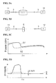
- Figures 1A to 1D are conceptual diagrams illustrating a cutoff wavelength measuring method using the bend reference technique.
- Figures 2A to 2D are conceptual diagrams illustrating a cutoff wavelength measuring method using the multimode reference technique.
- Figures 3A to 3D are conceptual diagrams illustrating a cutoff wavelength measuring method according to an embodiment of the present invention.
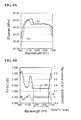
- Figures 4A to 4C are graphs for explaining details of the cutoff wavelength measuring method according to the embodiment of the present invention.
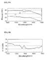
- Figure 5 is a graph showing a first power spectrum S1 and a second power spectrum S2 that corresponds to each of three measuring methods.
- Figure 6 is a graph showing a difference spectrum (S1 - S2) determined by each of the three measuring methods.
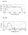
- Figure 7A is a graph showing a first power spectrum S1 and a second power spectrum S2 determined by the bend reference technique.
- Figure 7B is a graph showing the corresponding difference spectrum (S1 - S2).
- Figure 8A is a graph showing a first power spectrum S1 and a second power spectrum S2 determined by the multimode reference technique.
- Figure 8B is a graph showing the corresponding difference spectrum (S1 - S2).
- Figure 9A is a graph showing a first power spectrum S1 and a second power spectrum S2 determined by the multimode reference technique.
- Figure 9B is a graph showing the corresponding difference spectrum (S1 - S2).
- Figure 10A is a graph showing a first power spectrum S1 and a second power spectrum S2 determined by the method according to the embodiment of the present invention.
- Figure 10B is a graph showing the corresponding difference spectrum (S1 - S2).
- Figures 1A to 1D are conceptual diagrams illustrating a cutoff wavelength measuring method using the bend reference technique.
- a multimode fiber 2 is butt-joined to a first end of an optical fiber (specimen) under test I whose higher-order mode cutoff wavelength ⁇ c is to be measured, while a multimode fiber 3 is butt-joined to a second end of the specimen 1 (see Fig. 1A ).
- Light output from a light source 11 is allowed to propagate through the multimode fiber 2, the specimen 1, and the multimode fiber 3 in this order.
- the intensity of light exiting from the multimode fiber 3 is measured by a detector assembly 12.
- a first power spectrum S1 is determined on the basis of the measured intensity of light.
- the exit end of the specimen 1 is wound to form a smaller diameter bend 4, which blocks higher-order mode light from passing therethrough in a measurement wavelength range (see Fig. 1B ).
- Light output from the light source 11 is allowed to propagate through the multimode fiber 2, the specimen 1, the smaller diameter bend 4, and the multimode fiber 3 in this order.
- the intensity of light exiting from the multimode fiber 3 is measured by the detector assembly 12.
- a second power spectrum S2 is determined on the basis of the measured intensity of light.
- the specimen 1 is set to 2 m in length and wound with a diameter of 280 mm.
- the exit end of the specimen 1 is wound with a small diameter of 60 mm or less.
- the first power spectrum S1 has large power on a shorter wavelength side where wavelengths are shorter than the cutoff wavelength ⁇ c of the specimen 1 since the first power spectrum S1 contains higher-order modes as well as a fundamental mode on the shorter wavelength side, while the first power spectrum S1 has small power on a longer wavelength side where wavelengths are longer than the cutoff wavelength ⁇ c of the specimen 1 since the first power spectrum S1 contains only the fundamental mode on the longer wavelength side.
- the second power spectrum S2 has small power even on the shorter wavelength side since power of the higher order mode attenuated by additional bend.
- Figures 2A to 2D are conceptual diagrams illustrating a cutoff wavelength measuring method using the multimode reference technique.
- the optical fiber under test (specimen) 1, the multimode fiber 2, and the multimode fiber 3 are arranged in the same manner as that in the bend reference technique (see Fig. 2A ).
- the specimen 1 is set to 2 m in length and wound with a diameter of 280 mm.
- Light output from the light source 11 is allowed to propagate through the multimode fiber 2, the specimen 1, and the multimode fiber 3 in this order.
- the intensity of light exiting from the multimode fiber 3 is measured by the detector assembly 12.
- a first power spectrum S1 is determined on the basis of the measured intensity of light.
- a multimode fiber 5 is inserted between the multimode fiber 2 and the multimode fiber 3 (see Fig. 2B ).
- Light output from the light source 11 is allowed to propagate through the multimode fiber 2, the multimode fiber 5, and the multimode fiber 3 in this order.
- the intensity of light exiting from the multimode fiber 3 is measured by the detector assembly 12.
- a second power spectrum S2 is determined on the basis of the measured intensity of light.
- the first power spectrum S1 has large power on a shorter wavelength side where wavelengths are shorter than the cutoff wavelength ⁇ c of the specimen I since the first power spectrum S1 contains higher-order modes as well as a fundamental mode on the shorter wavelength side, while the first power spectrum S1 has small power on a longer wavelength side where wavelengths are longer than the cutoff wavelength ⁇ c of the specimen 1 since the first power spectrum S1 contains only the fundamental mode on the longer wavelength side.
- the second power spectrum S2 has large power as it contains the higher-order modes as well as the fundamental mode.
- Figures 3A to 3D are conceptual diagrams illustrating a cutoff wavelength measuring method according to an embodiment of the present invention.
- the multimode fiber 2 in a first step, is butt-joined to the first end of the optical fiber under test (specimen) 1, while the multimode fiber 3 is butt-joined to the second end of the specimen 1 (see Fig. 3A ).
- Light output from the light source 11 is allowed to propagate through the multimode fiber 2, the specimen 1, and the multimode fiber 3 in this order.
- the intensity of light exiting from the multimode fiber 3 is measured by the detector assembly 12.
- a first power spectrum S1 is determined on the basis of the measured intensity of light.
- the specimen 1 is replaced with a reference fiber 6.
- the multimode fiber 2 is butt-joined to a first end of the reference fiber 6, while the multimode fiber 3 is butt-joined to a second end of the reference fiber 6 (see Fig. 3B ).
- Light output from a light source 11 is allowed to propagate through the multimode fiber 2, the reference fiber 6, and the multimode fiber 3 in this order.
- the intensity of light exiting from the multimode fiber 3 is measured by the detector assembly 12.
- a second power spectrum S2 is determined on the basis of the measured intensity of light.
- the specimen 1 may be set to 2 m in length and wound with a diameter of 280 mm.
- the specimen 1 may be placed in a use environment of an optical transmission path etc. or under conditions equivalent to the use environment.
- the reference fiber 6 has bending loss higher than that of the specimen 1 in a predetermined wavelength range, and has a cutoff wavelength shorter than the cutoff wavelength ⁇ c of the specimen 1. It is preferable to set the length, the bending diameter, or the number of turns of the reference fiber 6 such that the first power spectrum S1 is larger than the second power spectrum S2 on a longer wavelength side where wavelengths are longer than the cutoff wavelength of the reference fiber 6. It is also preferable, in the predetermined wavelength range, that a difference in mode field diameter between the specimen 1 and the reference fiber 6 be 0.5 ⁇ m or less.
- the reference fiber 6 is preferably a low-OH loss fiber compliant with the ITU-T G.652.D standard.
- the reference fiber 6 may be of any length, but can preferably be elongated within a range where the transmission loss does not exceed 0.01 dB.
- the reference fiber 6 is preferably 2 m to 10 m in length.
- the reference fiber 6 may be wound around a mandrel within a range where the bending loss at the cutoff wavelength ⁇ c of the specimen 1 does not exceed 0.01 dB.
- the reference fiber 6 is preferably wound around a 60-mm diameter mandrel. Thus, it is possible to shorten the cutoff wavelength of the reference fiber 6 and extend the range of measurement.
- the first power spectrum S1 has large power on a shorter wavelength side where wavelengths are shorter than the cutoff wavelength ⁇ c of the specimen I since the first power spectrum S1 contains higher-order modes as well as a fundamental mode on the shorter wavelength side, while the first power spectrum S1 has small power on a longer wavelength side where wavelengths are longer than the cutoff wavelength ⁇ c of the specimen 1 since the first power spectrum S1 contains only the fundamental mode on the longer wavelength side.
- the second power spectrum S2 has large power on a shorter wavelength side where wavelengths are shorter than the cutoff wavelength of the reference fiber 6, the cutoff wavelength being shorter than the cutoff wavelength ⁇ c of the specimen 1, since the second power spectrum S2 contains higher-order modes as well as the fundamental mode on the shorter wavelength side.
- the second power spectrum S2 has small power on a longer wavelength side where wavelengths are longer than the cutoff wavelength of the reference fiber 6 since the second power spectrum S2 contains only the fundamental mode on the longer wavelength side.
- a difference spectrum is determined by subtracting the second power spectrum S2 from the first power spectrum S1.
- the higher-order mode cutoff wavelength ⁇ c of the specimen 1 is determined on the basis of the shape of the difference spectrum.
- Figures 4A to 4C are graphs for explaining details of the cutoff wavelength measuring method according to the embodiment of the present invention.
- Figure 4A shows the first power spectrum S1 obtained in the first step and the second power spectrum S2 obtained in the second step.
- a difference spectrum (indicated by a solid line) is determined by subtracting the second power spectrum S2 from the first power spectrum S1.
- a specific range where a difference from a minimum value of the difference spectrum is less than 0.1 dB and a derivative (indicated by a dotted line) of the difference spectrum (S1 - S2) is substantially 0 is determined.
- an average value A of the difference spectrum in the specific range is determined.
- a straight line representing a value B that is 0.1 dB larger than the average value A is drawn, and a wavelength at an intersection point of the difference spectrum and the straight line is determined.
- Figures 5 and 6 are graphs each comparing results of measurements performed by the three measuring methods, that is, the bend reference technique, the multimode reference technique, and the method according to the embodiment of the present invention.
- Figure 5 is a graph showing the first power spectrum S1 and the second power spectra S2.
- Figure 6 is a graph showing the corresponding difference spectra (S1 - S2).
- the cutoff wavelength ⁇ c of the common specimen 1 was measured by each of the three measuring methods.
- Table shows the cutoff wavelength ⁇ c of the specimen 1, the cutoff wavelength ⁇ c being measured by each of the three measuring methods.
- Table Measuring method Determined wavelength nm Bend reference technique 1277 Multimode reference technique 1290 Embodiment 1281 The measured cutoff wavelengths ⁇ c obtained by the three measuring methods well agree with each other.
- Figures 7A, 7B , 8A, 8B , 9A, 9B , 10A, and 10B are graphs for comparing examples of the cutoff wavelengths ⁇ c measured by the three measuring methods, that is, the bend reference technique, the multimode reference technique, and the method according to the embodiment of the present invention.
- the cutoff wavelengths ⁇ c of different specimens were measured.
- Figure 7A is a graph showing a first power spectrum S1 and a second power spectrum S2 obtained by the bend reference technique using an optical fiber having low bending loss in higher-order modes as a specimen.
- Figure 7B is a graph showing the corresponding difference spectrum (S1 - S2). Since the difference between the first power spectrum S1 and the second power spectrum S2 is small, it was difficult to measure the cutoff wavelength ⁇ c of the specimen.
- Figure 8A is a graph showing a first power spectrum S1 and a second power spectrum S2 obtained by the multimode reference technique using an optical fibers having a plurality of higher-order mode cutoff wavelengths close to each other as specimens.
- Figure 8B is a graph showing the corresponding difference spectrum (S1 - S2). As shown in Fig. 8B , since there are a plurality of peaks close to each other (as indicated by arrows) in the difference spectrum (S1 - S2), it was difficult to measure the cutoff wavelength ⁇ c of the specimens.
- Figure 9A is a graph showing a first power spectrum S1 and a second power spectrum S2 obtained by the multimode reference technique using an optical fiber having the cutoff wavelength ⁇ c close to an OH loss wavelength (i.e., a wavelength position enclosed with a dotted line) as a specimen.
- Figure 9B is a graph showing the corresponding difference spectrum (S1 - S2). Since the effect of OH loss of the multimode fibers 2 and 3 appears in the difference spectrum, it was difficult to measure the cutoff wavelength ⁇ c of the specimen.
- Figure 10A is a graph showing a first power spectrum S1 and a second power spectrum S2 obtained by the method according to the embodiment of the present invention.
- Figure 10B is a graph showing the corresponding difference spectrum (S1 - S2).
- the cutoff wavelength measuring method it is possible to measure a higher-order mode cutoff wavelength of a specimen for which it is difficult to measure its cutoff wavelength with a known method. Therefore, when the cutoff wavelength measuring method according to the embodiment of the present invention is used to measure a higher-order mode cutoff wavelength of an optical fiber and signal light having a wavelength longer than the thus measured cutoff wavelength of the optical fiber is transmitted, it is possible to create a reliable optical communication system for single-mode transmission.
Landscapes
- Physics & Mathematics (AREA)
- Optics & Photonics (AREA)
- Chemical & Material Sciences (AREA)
- Analytical Chemistry (AREA)
- General Physics & Mathematics (AREA)
- Testing Of Optical Devices Or Fibers (AREA)
Applications Claiming Priority (2)
| Application Number | Priority Date | Filing Date | Title |
|---|---|---|---|
| US16467309P | 2009-03-30 | 2009-03-30 | |
| JP2009116542A JP5365338B2 (ja) | 2009-03-30 | 2009-05-13 | カットオフ波長測定方法および光通信システム |
Publications (4)
| Publication Number | Publication Date |
|---|---|
| EP2237010A2 true EP2237010A2 (de) | 2010-10-06 |
| EP2237010A3 EP2237010A3 (de) | 2016-11-02 |
| EP2237010B1 EP2237010B1 (de) | 2017-12-13 |
| EP2237010B8 EP2237010B8 (de) | 2018-02-14 |
Family
ID=42289574
Family Applications (1)
| Application Number | Title | Priority Date | Filing Date |
|---|---|---|---|
| EP10158144.5A Not-in-force EP2237010B8 (de) | 2009-03-30 | 2010-03-29 | Grenzwellenlängen-Messverfahren und optisches Kommunikationssystem |
Country Status (3)
| Country | Link |
|---|---|
| US (1) | US8223323B2 (de) |
| EP (1) | EP2237010B8 (de) |
| CN (1) | CN101854210B (de) |
Families Citing this family (9)
| Publication number | Priority date | Publication date | Assignee | Title |
|---|---|---|---|---|
| US7463812B2 (en) * | 2007-01-19 | 2008-12-09 | Adc Telecommunications, Inc. | Overhead cable termination arrangement |
| US8625944B1 (en) * | 2009-05-13 | 2014-01-07 | Draka Comteq, B.V. | Low-shrink reduced-diameter buffer tubes |
| US8625945B1 (en) * | 2009-05-13 | 2014-01-07 | Draka Comteq, B.V. | Low-shrink reduced-diameter dry buffer tubes |
| CN102752047B (zh) * | 2012-07-27 | 2015-05-06 | 索尔思光电(成都)有限公司 | 光器件的故障检测方法及系统 |
| JP6402482B2 (ja) * | 2014-04-30 | 2018-10-10 | 住友電気工業株式会社 | 光ファイバのカットオフ波長測定方法 |
| US20160218802A1 (en) * | 2015-01-28 | 2016-07-28 | Exfo Inc. | Method and system for measuring an optical power attenuation value of a multimode device under test, receive device and computer-readable memory |
| US9825700B2 (en) | 2015-01-28 | 2017-11-21 | Exfo Inc. | Method and system for measuring an optical power attenuation value of a multimode device under test, receive device and computer-readable memory |
| CN105954011A (zh) * | 2016-06-03 | 2016-09-21 | 中天科技光纤有限公司 | 一种光纤宏弯损耗测试方法及测试系统 |
| JP7396304B2 (ja) * | 2019-01-24 | 2023-12-12 | ソニーグループ株式会社 | 光通信装置、光通信方法および光通信システム |
Family Cites Families (7)
| Publication number | Priority date | Publication date | Assignee | Title |
|---|---|---|---|---|
| IT1157969B (it) * | 1982-12-14 | 1987-02-18 | Cselt Centro Studi Lab Telecom | Procedimento per la misura della lunghezza d'onda di taglio del primo modo d'ordine superiore in fibre ottiche |
| US4552578A (en) * | 1983-05-16 | 1985-11-12 | At&T Bell Laboratories | Optical fiber fabrication process comprising determining mode field radius and cut-off wavelength of single mode optical fibers |
| IT1180071B (it) * | 1984-06-05 | 1987-09-23 | Cselt Centro Studi Lab Telecom | Procedimento e apparecchiatura per la misura della lunghezza d'onda di taglio del primo modo d'ordine superiore in fibre ottiche |
| JPS61116634A (ja) * | 1984-11-09 | 1986-06-04 | Hamamatsu Photonics Kk | 光フアイバの伝送特性を計測する装置 |
| JPS61128134A (ja) * | 1984-11-26 | 1986-06-16 | Sumitomo Electric Ind Ltd | 単一モ−ド光フアイバのカツトオフ波長測定装置 |
| JPS63218838A (ja) * | 1987-03-09 | 1988-09-12 | Nippon Telegr & Teleph Corp <Ntt> | 光フアイバ遮断波長検定方法 |
| NL1023909C2 (nl) * | 2003-07-11 | 2005-01-12 | Draka Fibre Technology Bv | Werkwijze voor het bepalen van de afsnijgolflengte van een optische vezel, alsmede een daarvoor geschikte inrichting. |
-
2010
- 2010-03-29 EP EP10158144.5A patent/EP2237010B8/de not_active Not-in-force
- 2010-03-30 US US12/750,029 patent/US8223323B2/en not_active Expired - Fee Related
- 2010-03-30 CN CN2010101398272A patent/CN101854210B/zh not_active Expired - Fee Related
Non-Patent Citations (1)
| Title |
|---|
| M. IKEDA, FUJIKURA GIHO, 2003, pages 6 - 10 |
Also Published As
| Publication number | Publication date |
|---|---|
| EP2237010B1 (de) | 2017-12-13 |
| EP2237010B8 (de) | 2018-02-14 |
| US8223323B2 (en) | 2012-07-17 |
| CN101854210B (zh) | 2013-06-19 |
| US20100247093A1 (en) | 2010-09-30 |
| EP2237010A3 (de) | 2016-11-02 |
| CN101854210A (zh) | 2010-10-06 |
Similar Documents
| Publication | Publication Date | Title |
|---|---|---|
| EP2237010B1 (de) | Grenzwellenlängen-Messverfahren und optisches Kommunikationssystem | |
| US8988669B2 (en) | Power monitor for optical fiber using background scattering | |
| KR20160145049A (ko) | 비접촉 광 전력 측정을 위한 시스템 및 방법 | |
| US20230044386A1 (en) | Optical fibre based measurment system, method of measuring parameters, and computer program product | |
| US7415206B1 (en) | Arrangement for characterizing and reducing multi-path interference (MPI) and/or optical return loss (ORL) in optical transmission links having multiple discrete reflection sources | |
| JPH0815092A (ja) | 光導波路ファイバのスペクトル減衰を測定する方法 | |
| US9395242B2 (en) | Broadband fiber sensor array | |
| JP2012150002A (ja) | 遮断波長測定方法および動作モード判定方法、並びにその装置 | |
| DK2237010T3 (en) | Boundary wavelength measurement method and optical communication system | |
| Chen et al. | Angle-resolved characterization and ray-optics modeling of fiber-optic sensors | |
| CN111256960B (zh) | 一种光器件、光芯片损耗测试装置及方法 | |
| JP4246037B2 (ja) | 光線路特性の解析方法及び光線路試験監視システム | |
| Iho et al. | Characterization of modal coupling of Bragg gratings in large-mode-area fibers | |
| JP3388497B2 (ja) | 単一モード光ファイバの特性評価方法 | |
| JP2002303741A (ja) | シングルモード光ファイバ用ガラス母材及びシングルモード光ファイバ並びにその評価方法 | |
| KR100832470B1 (ko) | 광섬유의 복굴절 측정 방법 및 측정 장치, 광섬유의 편파모드 분산 측정 방법 및 광섬유 | |
| JP2006078378A (ja) | 光ファイバの測長方法 | |
| Siuzdak et al. | Influence of modal filtering on the bandwidth of multimode optical fibers | |
| US11754466B2 (en) | Mode-dependent loss measurement device and mode-dependent loss measuring method | |
| JP7376410B2 (ja) | 測定方法及び測定装置 | |
| JP5350841B2 (ja) | 光ファイバコード評価方法及び装置 | |
| Wei et al. | Extraction of Attenuation and Backscattering Coefficient along Hollow-Core Fiber Length Using Two-Way Optical Time Domain Backscattering | |
| Bezawada et al. | Experimental Characterization of Attenuation at 1240 nm and 1310 nm for Bend Insensitive Optical Fibers | |
| Coppa et al. | Single-mode optical fiber characterization | |
| Olivero et al. | Near-field measurements and mode power distribution of multimode optical fibers |
Legal Events
| Date | Code | Title | Description |
|---|---|---|---|
| PUAI | Public reference made under article 153(3) epc to a published international application that has entered the european phase |
Free format text: ORIGINAL CODE: 0009012 |
|
| 17P | Request for examination filed |
Effective date: 20100329 |
|
| AK | Designated contracting states |
Kind code of ref document: A2 Designated state(s): AT BE BG CH CY CZ DE DK EE ES FI FR GB GR HR HU IE IS IT LI LT LU LV MC MK MT NL NO PL PT RO SE SI SK SM TR |
|
| AX | Request for extension of the european patent |
Extension state: AL BA ME RS |
|
| PUAL | Search report despatched |
Free format text: ORIGINAL CODE: 0009013 |
|
| AK | Designated contracting states |
Kind code of ref document: A3 Designated state(s): AT BE BG CH CY CZ DE DK EE ES FI FR GB GR HR HU IE IS IT LI LT LU LV MC MK MT NL NO PL PT RO SE SI SK SM TR |
|
| AX | Request for extension of the european patent |
Extension state: AL BA ME RS |
|
| RIC1 | Information provided on ipc code assigned before grant |
Ipc: G01M 11/00 20060101AFI20160926BHEP |
|
| GRAP | Despatch of communication of intention to grant a patent |
Free format text: ORIGINAL CODE: EPIDOSNIGR1 |
|
| INTG | Intention to grant announced |
Effective date: 20170802 |
|
| GRAS | Grant fee paid |
Free format text: ORIGINAL CODE: EPIDOSNIGR3 |
|
| GRAA | (expected) grant |
Free format text: ORIGINAL CODE: 0009210 |
|
| AK | Designated contracting states |
Kind code of ref document: B1 Designated state(s): AT BE BG CH CY CZ DE DK EE ES FI FR GB GR HR HU IE IS IT LI LT LU LV MC MK MT NL NO PL PT RO SE SI SK SM TR |
|
| REG | Reference to a national code |
Ref country code: GB Ref legal event code: FG4D |
|
| REG | Reference to a national code |
Ref country code: AT Ref legal event code: REF Ref document number: 954854 Country of ref document: AT Kind code of ref document: T Effective date: 20171215 Ref country code: CH Ref legal event code: EP |
|
| GRAT | Correction requested after decision to grant or after decision to maintain patent in amended form |
Free format text: ORIGINAL CODE: EPIDOSNCDEC |
|
| RAP2 | Party data changed (patent owner data changed or rights of a patent transferred) |
Owner name: SUMITOMO ELECTRIC INDUSTRIES, LTD. |
|
| REG | Reference to a national code |
Ref country code: IE Ref legal event code: FG4D |
|
| REG | Reference to a national code |
Ref country code: DE Ref legal event code: R096 Ref document number: 602010047300 Country of ref document: DE |
|
| REG | Reference to a national code |
Ref country code: DK Ref legal event code: T3 Effective date: 20180116 |
|
| REG | Reference to a national code |
Ref country code: NL Ref legal event code: FP |
|
| REG | Reference to a national code |
Ref country code: LT Ref legal event code: MG4D |
|
| PG25 | Lapsed in a contracting state [announced via postgrant information from national office to epo] |
Ref country code: SE Free format text: LAPSE BECAUSE OF FAILURE TO SUBMIT A TRANSLATION OF THE DESCRIPTION OR TO PAY THE FEE WITHIN THE PRESCRIBED TIME-LIMIT Effective date: 20171213 Ref country code: FI Free format text: LAPSE BECAUSE OF FAILURE TO SUBMIT A TRANSLATION OF THE DESCRIPTION OR TO PAY THE FEE WITHIN THE PRESCRIBED TIME-LIMIT Effective date: 20171213 Ref country code: NO Free format text: LAPSE BECAUSE OF FAILURE TO SUBMIT A TRANSLATION OF THE DESCRIPTION OR TO PAY THE FEE WITHIN THE PRESCRIBED TIME-LIMIT Effective date: 20180313 Ref country code: LT Free format text: LAPSE BECAUSE OF FAILURE TO SUBMIT A TRANSLATION OF THE DESCRIPTION OR TO PAY THE FEE WITHIN THE PRESCRIBED TIME-LIMIT Effective date: 20171213 |
|
| REG | Reference to a national code |
Ref country code: AT Ref legal event code: MK05 Ref document number: 954854 Country of ref document: AT Kind code of ref document: T Effective date: 20171213 |
|
| PG25 | Lapsed in a contracting state [announced via postgrant information from national office to epo] |
Ref country code: GR Free format text: LAPSE BECAUSE OF FAILURE TO SUBMIT A TRANSLATION OF THE DESCRIPTION OR TO PAY THE FEE WITHIN THE PRESCRIBED TIME-LIMIT Effective date: 20180314 Ref country code: BG Free format text: LAPSE BECAUSE OF FAILURE TO SUBMIT A TRANSLATION OF THE DESCRIPTION OR TO PAY THE FEE WITHIN THE PRESCRIBED TIME-LIMIT Effective date: 20180313 Ref country code: LV Free format text: LAPSE BECAUSE OF FAILURE TO SUBMIT A TRANSLATION OF THE DESCRIPTION OR TO PAY THE FEE WITHIN THE PRESCRIBED TIME-LIMIT Effective date: 20171213 Ref country code: HR Free format text: LAPSE BECAUSE OF FAILURE TO SUBMIT A TRANSLATION OF THE DESCRIPTION OR TO PAY THE FEE WITHIN THE PRESCRIBED TIME-LIMIT Effective date: 20171213 |
|
| PG25 | Lapsed in a contracting state [announced via postgrant information from national office to epo] |
Ref country code: ES Free format text: LAPSE BECAUSE OF FAILURE TO SUBMIT A TRANSLATION OF THE DESCRIPTION OR TO PAY THE FEE WITHIN THE PRESCRIBED TIME-LIMIT Effective date: 20171213 Ref country code: CZ Free format text: LAPSE BECAUSE OF FAILURE TO SUBMIT A TRANSLATION OF THE DESCRIPTION OR TO PAY THE FEE WITHIN THE PRESCRIBED TIME-LIMIT Effective date: 20171213 Ref country code: CY Free format text: LAPSE BECAUSE OF FAILURE TO SUBMIT A TRANSLATION OF THE DESCRIPTION OR TO PAY THE FEE WITHIN THE PRESCRIBED TIME-LIMIT Effective date: 20171213 Ref country code: EE Free format text: LAPSE BECAUSE OF FAILURE TO SUBMIT A TRANSLATION OF THE DESCRIPTION OR TO PAY THE FEE WITHIN THE PRESCRIBED TIME-LIMIT Effective date: 20171213 Ref country code: SK Free format text: LAPSE BECAUSE OF FAILURE TO SUBMIT A TRANSLATION OF THE DESCRIPTION OR TO PAY THE FEE WITHIN THE PRESCRIBED TIME-LIMIT Effective date: 20171213 |
|
| PG25 | Lapsed in a contracting state [announced via postgrant information from national office to epo] |
Ref country code: IS Free format text: LAPSE BECAUSE OF FAILURE TO SUBMIT A TRANSLATION OF THE DESCRIPTION OR TO PAY THE FEE WITHIN THE PRESCRIBED TIME-LIMIT Effective date: 20180413 Ref country code: RO Free format text: LAPSE BECAUSE OF FAILURE TO SUBMIT A TRANSLATION OF THE DESCRIPTION OR TO PAY THE FEE WITHIN THE PRESCRIBED TIME-LIMIT Effective date: 20171213 Ref country code: IT Free format text: LAPSE BECAUSE OF FAILURE TO SUBMIT A TRANSLATION OF THE DESCRIPTION OR TO PAY THE FEE WITHIN THE PRESCRIBED TIME-LIMIT Effective date: 20171213 Ref country code: SM Free format text: LAPSE BECAUSE OF FAILURE TO SUBMIT A TRANSLATION OF THE DESCRIPTION OR TO PAY THE FEE WITHIN THE PRESCRIBED TIME-LIMIT Effective date: 20171213 Ref country code: AT Free format text: LAPSE BECAUSE OF FAILURE TO SUBMIT A TRANSLATION OF THE DESCRIPTION OR TO PAY THE FEE WITHIN THE PRESCRIBED TIME-LIMIT Effective date: 20171213 Ref country code: PL Free format text: LAPSE BECAUSE OF FAILURE TO SUBMIT A TRANSLATION OF THE DESCRIPTION OR TO PAY THE FEE WITHIN THE PRESCRIBED TIME-LIMIT Effective date: 20171213 |
|
| REG | Reference to a national code |
Ref country code: DE Ref legal event code: R097 Ref document number: 602010047300 Country of ref document: DE |
|
| REG | Reference to a national code |
Ref country code: DE Ref legal event code: R119 Ref document number: 602010047300 Country of ref document: DE |
|
| PLBE | No opposition filed within time limit |
Free format text: ORIGINAL CODE: 0009261 |
|
| STAA | Information on the status of an ep patent application or granted ep patent |
Free format text: STATUS: NO OPPOSITION FILED WITHIN TIME LIMIT |
|
| REG | Reference to a national code |
Ref country code: CH Ref legal event code: PL |
|
| 26N | No opposition filed |
Effective date: 20180914 |
|
| GBPC | Gb: european patent ceased through non-payment of renewal fee |
Effective date: 20180329 |
|
| PG25 | Lapsed in a contracting state [announced via postgrant information from national office to epo] |
Ref country code: MC Free format text: LAPSE BECAUSE OF FAILURE TO SUBMIT A TRANSLATION OF THE DESCRIPTION OR TO PAY THE FEE WITHIN THE PRESCRIBED TIME-LIMIT Effective date: 20171213 |
|
| REG | Reference to a national code |
Ref country code: BE Ref legal event code: MM Effective date: 20180331 |
|
| REG | Reference to a national code |
Ref country code: IE Ref legal event code: MM4A |
|
| PG25 | Lapsed in a contracting state [announced via postgrant information from national office to epo] |
Ref country code: LU Free format text: LAPSE BECAUSE OF NON-PAYMENT OF DUE FEES Effective date: 20180329 |
|
| PG25 | Lapsed in a contracting state [announced via postgrant information from national office to epo] |
Ref country code: IE Free format text: LAPSE BECAUSE OF NON-PAYMENT OF DUE FEES Effective date: 20180329 Ref country code: DE Free format text: LAPSE BECAUSE OF NON-PAYMENT OF DUE FEES Effective date: 20181002 |
|
| PG25 | Lapsed in a contracting state [announced via postgrant information from national office to epo] |
Ref country code: LI Free format text: LAPSE BECAUSE OF NON-PAYMENT OF DUE FEES Effective date: 20180331 Ref country code: CH Free format text: LAPSE BECAUSE OF NON-PAYMENT OF DUE FEES Effective date: 20180331 Ref country code: SI Free format text: LAPSE BECAUSE OF FAILURE TO SUBMIT A TRANSLATION OF THE DESCRIPTION OR TO PAY THE FEE WITHIN THE PRESCRIBED TIME-LIMIT Effective date: 20171213 Ref country code: BE Free format text: LAPSE BECAUSE OF NON-PAYMENT OF DUE FEES Effective date: 20180331 Ref country code: GB Free format text: LAPSE BECAUSE OF NON-PAYMENT OF DUE FEES Effective date: 20180329 |
|
| PG25 | Lapsed in a contracting state [announced via postgrant information from national office to epo] |
Ref country code: FR Free format text: LAPSE BECAUSE OF NON-PAYMENT OF DUE FEES Effective date: 20180331 |
|
| PG25 | Lapsed in a contracting state [announced via postgrant information from national office to epo] |
Ref country code: MT Free format text: LAPSE BECAUSE OF NON-PAYMENT OF DUE FEES Effective date: 20180329 |
|
| PG25 | Lapsed in a contracting state [announced via postgrant information from national office to epo] |
Ref country code: TR Free format text: LAPSE BECAUSE OF FAILURE TO SUBMIT A TRANSLATION OF THE DESCRIPTION OR TO PAY THE FEE WITHIN THE PRESCRIBED TIME-LIMIT Effective date: 20171213 |
|
| PG25 | Lapsed in a contracting state [announced via postgrant information from national office to epo] |
Ref country code: PT Free format text: LAPSE BECAUSE OF FAILURE TO SUBMIT A TRANSLATION OF THE DESCRIPTION OR TO PAY THE FEE WITHIN THE PRESCRIBED TIME-LIMIT Effective date: 20171213 Ref country code: HU Free format text: LAPSE BECAUSE OF FAILURE TO SUBMIT A TRANSLATION OF THE DESCRIPTION OR TO PAY THE FEE WITHIN THE PRESCRIBED TIME-LIMIT; INVALID AB INITIO Effective date: 20100329 |
|
| PG25 | Lapsed in a contracting state [announced via postgrant information from national office to epo] |
Ref country code: MK Free format text: LAPSE BECAUSE OF NON-PAYMENT OF DUE FEES Effective date: 20171213 |
|
| PGFP | Annual fee paid to national office [announced via postgrant information from national office to epo] |
Ref country code: NL Payment date: 20210212 Year of fee payment: 12 |
|
| PGFP | Annual fee paid to national office [announced via postgrant information from national office to epo] |
Ref country code: DK Payment date: 20210310 Year of fee payment: 12 |
|
| REG | Reference to a national code |
Ref country code: DK Ref legal event code: EBP Effective date: 20220331 |
|
| REG | Reference to a national code |
Ref country code: NL Ref legal event code: MM Effective date: 20220401 |
|
| PG25 | Lapsed in a contracting state [announced via postgrant information from national office to epo] |
Ref country code: NL Free format text: LAPSE BECAUSE OF NON-PAYMENT OF DUE FEES Effective date: 20220401 |
|
| PG25 | Lapsed in a contracting state [announced via postgrant information from national office to epo] |
Ref country code: DK Free format text: LAPSE BECAUSE OF NON-PAYMENT OF DUE FEES Effective date: 20220331 |